Review

Heat Transfer Limitations in Supercritical Water Gasification

by
Francisco Javier Gutiérrez Ortiz
1,*,
Francisco López-Guirao
1,
Francisco José Jiménez-Espadafor
2 and
José Manuel Benjumea
2
1
Department of Chemical and Environmental Engineering, Escuela Técnica Superior de Ingeniería, Universidad de Sevilla, Camino de los Descubrimientos s/n, 41092 Sevilla, Spain
2
Department of Energy Engineering, Escuela Técnica Superior de Ingeniería, Universidad de Sevilla, Camino de los Descubrimientos s/n, 41092 Sevilla, Spain
*
Author to whom correspondence should be addressed.
Energies 2022, 15(1), 177; https://doi.org/10.3390/en15010177
Submission received: 12 November 2021 / Revised: 4 December 2021 / Accepted: 23 December 2021 / Published: 28 December 2021
(This article belongs to the Special Issue Waste-to-Energy Processes Using Supercritical Fluids)

Abstract

:
Supercritical water gasification (SCWG) is a promising technology for the valorization of wet biomass with a high-water content, which has attracted increasing interest. Many experimental studies have been carried out using conventional heating equipment at lab scale, where researchers try to obtain insight into the process. However, heat transfer from the energy source to the fluid stream entering the reactor may be ineffective, so slow heating occurs that produces a series of undesirable reactions, especially char formation and tar formation. This paper reviews the limitations due to different factors affecting heat transfer, such as low Reynolds numbers or laminar flow regimes, unknown real fluid temperature as this is usually measured on the tubing surface, the strong change in physical properties of water from subcritical to supercritical that boosts a deterioration in heat transfer, and the insufficient mixing, among others. In addition, some troubleshooting and new perspectives in the design of efficient and effective devices are described and proposed to enhance heat transfer, which is an essential aspect in the experimental studies of SCWG to move it forward to a larger scale.

1. Introduction

Supercritical water gasification (SCWG) is a promising technology that has attracted the interest of many researchers around the world for the past two decades. The main application of SCWG is wet biomass, as no feed drying is required. Supercritical water (SCW) has singular properties, such as a very low dielectric constant, lower density than liquid water, and transport properties similar to those of a gas, especially the viscosity that increases the diffusion coefficient [1,2,3]. These properties make it favorable as a medium, reactant, solvent, and even as a catalyst to convert organic material into syngas, mainly composed of H2, CO2, CO, and CH4.
Many studies on SCW gasification have been carried out, not only by experimentation but also by modeling and simulation. In fact, the general gasification reaction of an organic feed in SCW involves a series of coupled physical and chemical processes, including multiple reactions along with mass and heat transfer, in such a way that numerical simulation may overcome some drawbacks that occur in experimental methods to gain insight into the details of the gasification process under SCW conditions [4,5,6].
Similarly, there are review articles that deal with different aspects of SCWG, such as model compounds, lignocellulosic or microalgae biomass, types of reactors, energy and exergy, thermodynamics, catalysts, techno-economics, hydrogen production, modeling, and simulation [6,7,8,9,10,11,12,13,14,15,16,17], but there are few references to heat transfer in SCWG processes, especially at the lab scale, which is used most frequently in experimental studies carried out so far. In this regard, the heating rate/time applied to a specific reactor and how heat is transmitted from the energy source to the stream containing organic material and water that suffers a transition from subcritical to supercritical are crucial to understand the phenomena occurring inside the reactor and for scaling up.
Therefore, the reactor type applied to supercritical water gasification (SCWG) is of utmost importance. Three main types of reactors have been used. First, batch reactors with or without a stirrer, then tubular reactors, and finally fluidized-bed reactors. Regarding the topic of this review, the latter type of reactor allows the best heat transfer and appears to avoid or reduce some detected problems, especially in tubular reactors, such as plugging due to char formation [18]. In fact, char formation has been reported to occur at 200 °C and tar is formed mainly from 300 °C to the critical temperature of water [3], while other researchers have found that char and tar form more quickly between 350 and 370 °C [19]. These shortcomings are related to the heating section of the reactor, which is generally performed by an electric furnace. However, heat transfer in a fluidized bed is more complex than in a tubular reactor as it implies fluid, particles, and a reactor wall that includes mechanisms affecting all pairs of these elements (fluid-particles, etc.) due to heterogeneous flow within the bed [20]. Furthermore, in the operation of fluidized bed under SCW conditions, there is instability of the gas product, nonuniform temperature distribution, and particle overflow [21]. In addition, when SCWG is simulated in fluidized-bed reactors, the existing correlations of heat transfer may not be appropriate because the applicability and operation conditions can have a large deviation from those found in conventional fluidized beds, which requires more experimental research. There are a number of additional studies on this type of reactor [6,9,10,11,12], although the design of SCWG fluidized-bed reactors is currently incomplete, especially with respect to the heat transfer characteristics of SCW [22]. Further study on fluidized-bed reactors is required, as it is a promising type of reactor to be used on SCWG, especially when the technology is more developed and investment may be justified, which is easier using a simpler based-on tube reactor as next described, and fluidized-bed reactors are beyond the scope of this paper.
One of the aspects regarding tubular reactors is how to heat the stream entering the reactor and the inside of the reactor to avoid the operation problems mentioned above. The residence time in the tubular reactor is about a few seconds, which is much shorter than the reaction time in a batch reactor, where it is between minutes and hours. In fact, a prolonged reaction time leads gasification reactions to chemical equilibrium, thus greatly increasing the gas yield [23], one of the main objectives in SCWG. In spite of such a favorable potential result, it does not seem to be a good reactor type for scaling up the reactor to move the technology to an industrial scale. In addition, heat recovery in a batch reactor becomes difficult, but not in a continuous-flow reactor, so the latter concept is more appropriate for commercial application. Despite this, several studies using batch reactors can be found in the literature [24,25,26,27,28,29].
Therefore, most of the experimental research on SCWG has been carried out using tubular reactors [30,31,32,33,34,35,36,37,38] with the aim of addressing a future scale of the process. However, the design of this type of reactor may and must be improved to apply it to SCWG technology. One of the aspects related to heat transfer in the SCWG fluidized-bed reactor is the high heating rate, which is probably the solution to avoid the main operation problems in tubular rectors. Therefore, heat transfer and, specifically, the heating rate of the feed must be analyzed to improve the behavior of this type of reactor.
In the following sections, several aspects will be discussed in this short review, such as the heat transfer deterioration taking place at the lab scale, an analysis of heat transfer in experiments carried out at lab scale, a summary of limitations in experimental facilities, a series of potential troubleshooting, and proposals of new ways to boost the technology by improving the heat transfer performance in SCWG processes.

2. Heat Transfer Deterioration in SCWG Experiments

The abrupt changes that water undergoes in its physical properties near the critical point contribute to the deterioration of heat transfer, due to the decrease in turbulent thermal conductivity and eddy viscosity, leading to lower turbulent heat flux and therefore higher surface temperatures [39]. This deterioration may be the result of a significant density variation near the critical point that deforms the velocity profile, flagging the turbulence [5], or even due to the thickening of the viscous underlayer depending on the fluid flow rate [40]. Many research works, mainly performed numerically, have been published on this phenomenon, known as heat transfer deterioration (HTD) [41,42,43,44,45,46,47]. Recently, Wang et al. [48] obtained, by simulation, that semicircular heating decreased the degree of HTD due to the greater turbulence produced by the greater density difference between the heating side and the adiabatic side.
Figure 1 illustrates the trend of the physical properties of water versus temperature at 23 MPa and 25 MPa, obtained by [21], where the maximum values of specific heat and thermal conductivity define different pseudocritical temperatures; in fact, each pair (P, T) above the critical point leads to a pseudocritical point. The pseudocritical temperature increases as the (supercritical) pressure increases, and at this point and on, there is no longer a difference between the liquid and gas/vapor phases.
Regarding the change in water properties, at 25 MPa, a temperature variation from 377 °C to 393 °C, that is, about 4.2%, leads to a density change from 488.85 kg/m3 to 194.89 kg/m3, i.e., roughly 60% [49]. Therefore, viscosity and density are greatly reduced from subcritical to supercritical water conditions, thus improving mass transfer [50], although thermal conductivity decreases and specific heat capacity changes a lot [2].
The low flow rate in lab-scale reactors leads to deterioration in heat transfer due to buoyancy forces and flow acceleration, which is promoted by the change in physical properties during heating; therefore, this aspect should be taken into account when improving heat transfer performance.
In lab-scale research, low mass flow rates are commonly used, and although a tubing with a small internal diameter (ID) is also utilized, the fluid velocity is quite low, so turbulence is almost nonexistent.
A lower heating rate leads to longer residence and reaction times, but there is still a large section in the reactor with a lower temperature, thus forming char and tar. Therefore, it seems that there must be a trade-off between reaction time and heating rate with respect to the temperature increase experienced by the stream fed to the reactor, since the reactants are heated up at a certain rate clearly lower than the heating rate programmed for the heating process unit. As a consequence, a lapse of time is required to reach the reaction temperature. Consequently, this time needs to be minimized in the experimental facilities, thus inhibiting the formation of char and tar.
Heating of the reactor is mostly performed by external heating, typically with an electric radiant furnace, although it could also be carried out by internal heating from the fuel value of the feedstock in an autothermal operation, using a fraction of the gas produced in the process or even with an external fuel. These other options are not common at lab scale, and electric heating is most frequently used at lab scale, normally housing the reactor inside an electric furnace. In addition, preheating the reactor inlets and ducts upstream of the reactor is usually conducted using resistive wires or auxiliary radiant heaters [9].
Electric radiant furnaces are designed by considering a number of sections, each one with a temperature PID controller based on a thermocouple measuring the external wall of the reactor and using a thyristor or state-solid relay (SSR) as a final control element to switch on/off the resistor inside the correspondent furnace section. Several sections involve more sets of thermocouples, controllers, and SSR, but better temperature control can be achieved inside the furnace. It is common to preheat the electric furnace before entering the feed stream containing the organic compounds to approach the final reaction temperature. In addition, the heating may not be uniform throughout the reactor, as it has several meters of length, where liquid feed converts into supercritical in a section of reactor, so the properties change inside the reactor and oblige to activate the different SSR more or less, as these are linked to the controllers and thermocouples of each heating section. In this sense, a nonuniform temperature distribution along the pipe is another consequence of the slow and initially dense feed that may occur in the inlet zone of the reactor housed in the electric furnace. This non-uniformly heated tubular reactor needs to be treated as a transition process when modelling, despite steady-state equations frequently found in the literature to describe this process.
As mentioned above, the measurement of temperature of the stream at the reactor outlet is typically performed on the tubing external surface, and not inside the stream at high temperature and pressure, mainly for safety reasons, so the real fluid temperature is not usually measured in the section with the highest pressure and temperature.
Beyond the inlet zone of the reactor, another additional aspect that occurs is related to the transition from the subcritical to the supercritical fluid state, i.e., the effect of change in physical properties that leads to an intermediate zone inside the reactor, which is not well defined and is difficult to experimentally determine. A low Reynolds number characterizes the fluid flow, leading to a laminar flow regime where heat transfer is not effective enough and convection controls the heat transmission process. Additionally, as the temperature increases progressively and the transition from subcritical to supercritical states takes place, the Reynolds number changes significantly along the reactor as a result of the notable change experienced in both the density and the dynamic viscosity of water. However, the flow regime remains laminar. In fact, when the Reynolds number is expressed as a function of the mass flow rate, which is constant, the only property that affects the Reynolds number is the dynamic viscosity, and this changes from 10−3 Pa·s to about 3 × 10⁻⁵ Pa·s (Figure 1). Thus, the Reynolds number would be multiplied by a factor of up to 30 through the reactor, and still laminar flow regime is below 2300 (i.e., laminar flow), or perhaps slightly over, but always too low to achieve effective turbulent mixing. Furthermore, several researchers have reported deterioration in heat transfer [51] for SCW when the flow regime is laminar at a temperature higher than the pseudocritical temperature, where the properties of SCW are more gas-like at a given operating pressure. In this regard, at such low velocity, the effect of mixing is negligible, and heat transfer is poor.
As Kawasaki et al. [52] pointed out, the low mixing rate due to a low Reynolds number results in slow heating of the fluid through the stage in which the subcritical condition takes place, involving a low reaction rate and the appearance of primary and secondary nucleation that forms large char particles during the heating period.
The problem becomes more complex if the tubular reactor is vertically positioned instead horizontally, since the great change in density implies a significant buoyancy effect at low flow rates and flow acceleration at high flow rates; at laboratory scale, the first effect is the most relevant. Under these conditions, the velocity increases near the wall region so that the velocity profile is flattened, reducing the turbulent heat transfer coefficient, thus causing further deterioration of the heat transfer [53]. Moreover, some local turbulence may occur due to the higher flow near the wall produced by natural convection induced by gravity force related to the weighty change in density close to the pseudocritical temperature despite the laminar flow regime due to the low Reynolds numbers [51].

3. Experimental Deficiencies and Feasible Troubleshooting

When an experimental facility is assembled to study an SCWG process, the first attempt is to use an electric furnace that houses the reactor that heats the stream entering it. This has been applied by numerous researchers over the past two decades [54,55,56,57,58,59,60,61]. Heat is transmitted by radiation to the reactor wall, then by conduction through the wall, and finally by convection inside the reactor. Although the furnace power may be high to increase the heating rate inside the furnace at several tens of °C/min, the stream flowing inside the reactor is heating up more slowly, as the flow regime is laminar and the resistance to heat transfer by convection is larger than those of radiation and conduction. Thus, a Nusselt number of 3.66 (isothermal conditions) for forced convention in an internal circular tube leads to a significant decrease in the temperature of fluid, neglecting the rest of resistances due to radiation and conduction. As a consequence, the heating rate of the stream is slow, even though the heating rate of the electric device may be very high, and char and tar will form, as previously mentioned. If the feed is preheated in another equipment or by another electrical resistance, the problem will persist as the cause is not solved.
Reducing the reactor section to minimum would increase the velocity but decrease the residence time, which involves a higher length and an increase in pressure drop through the reactor, so there might be different pressures along the reactor. Although the heating rate would also increase as the inner diameter of the tube is decreased, there will be a section in the inlet zone with an insufficient temperature, clearly lower than the reaction temperature, leading to char formation and tar formation.
A possible solution consists of using two streams, one containing the organic load and the other containing only water [62,63,64,65]. Here, once the stream with only water is pumped to a pressure greater than 221 bar and preheated to the reaction temperature (higher than 374 °C) by resistive wires or a radiant furnace, it is mixed with the cold stream with the organic compounds before entering a second furnace aimed at holding the reaction temperature through a long reactor or a short reactor.
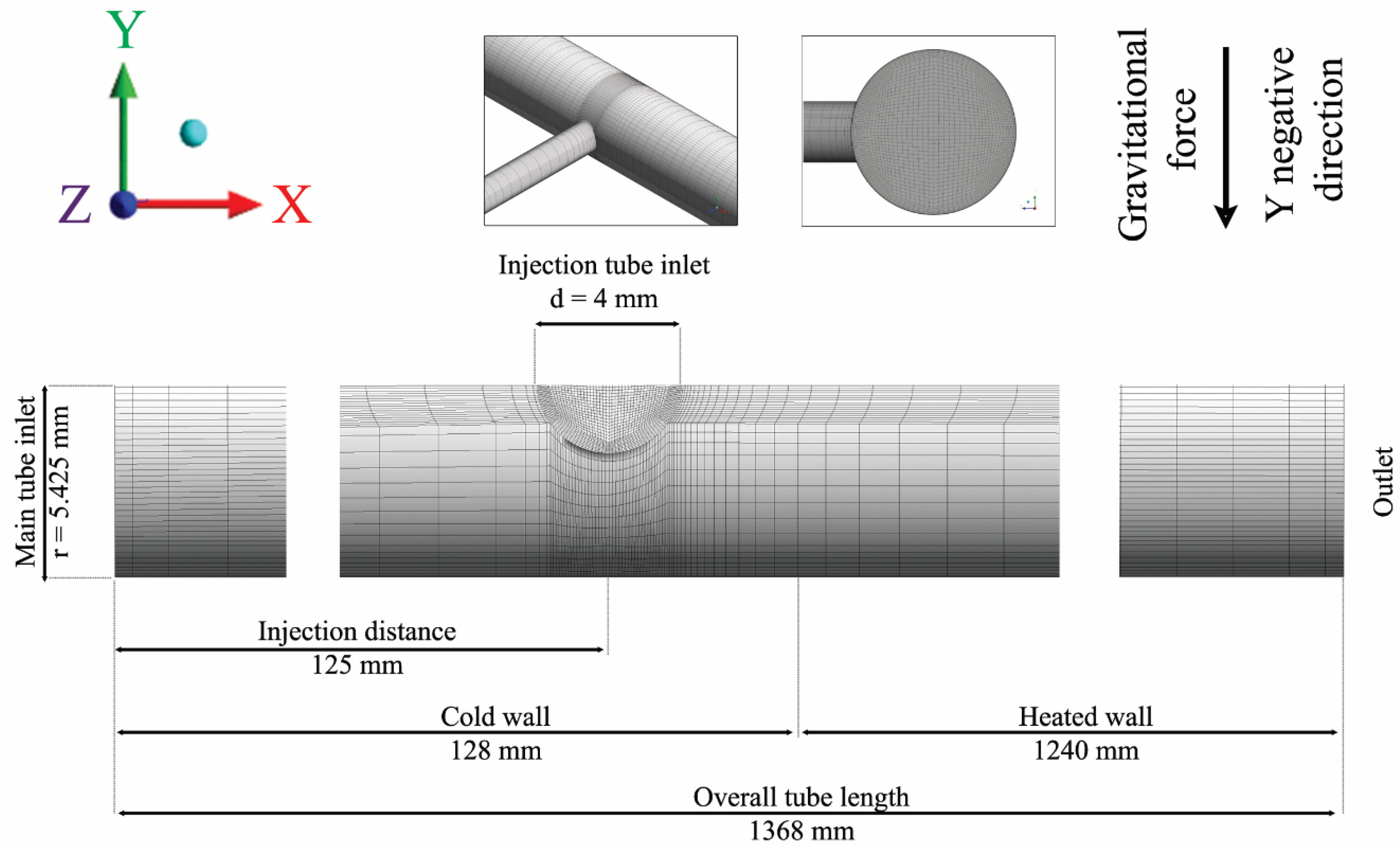
Yakunanto et al. [66] developed a computer fluid dynamics (CFD) model to gain insight into the flow pattern, mixing, and heat transfer during SCWG of glycerol simulating a tee fitting where the SCW stream and the cold glycerol stream were mixed. Their modeling output was compared with the experimental study carried out by Guo et al. [67], who used a 10.85 mm ID tube for the SCW stream and another 4 mm ID tube to inject the glycerol stream. The former was in a horizontal position and the latter in a vertical position. Figure 2 shows a scheme of this assembly. The authors reported that the simulation output was 6% higher than the experimentally measured outlet temperature. Furthermore, the authors verified that with a larger injection tube for glycerol, the recirculation inside the injection tube increased, leading to a longer preheating of the glycerol, which is negative because it leads to char formation, and a higher residence time, which is positive for achieving a higher gas yield. The opposite was found with a smaller injection tube. These researchers concluded that the best option was to use an injection tube with a small ID or increase the flow rate of the injection tube, thus reducing the partial heating caused by flow recirculation, and to position the tubular reactor horizontally.
This is an approach to try to overcome the slow heating, but there are also some aspects that put into question this way of operation: (1) it is not representative for scaling up the facility, as the feed stream is unique, especially, when the water content is as high as 80 wt.% or even more; and (2) slow heating also can occur in the mixing zone of the two streams.
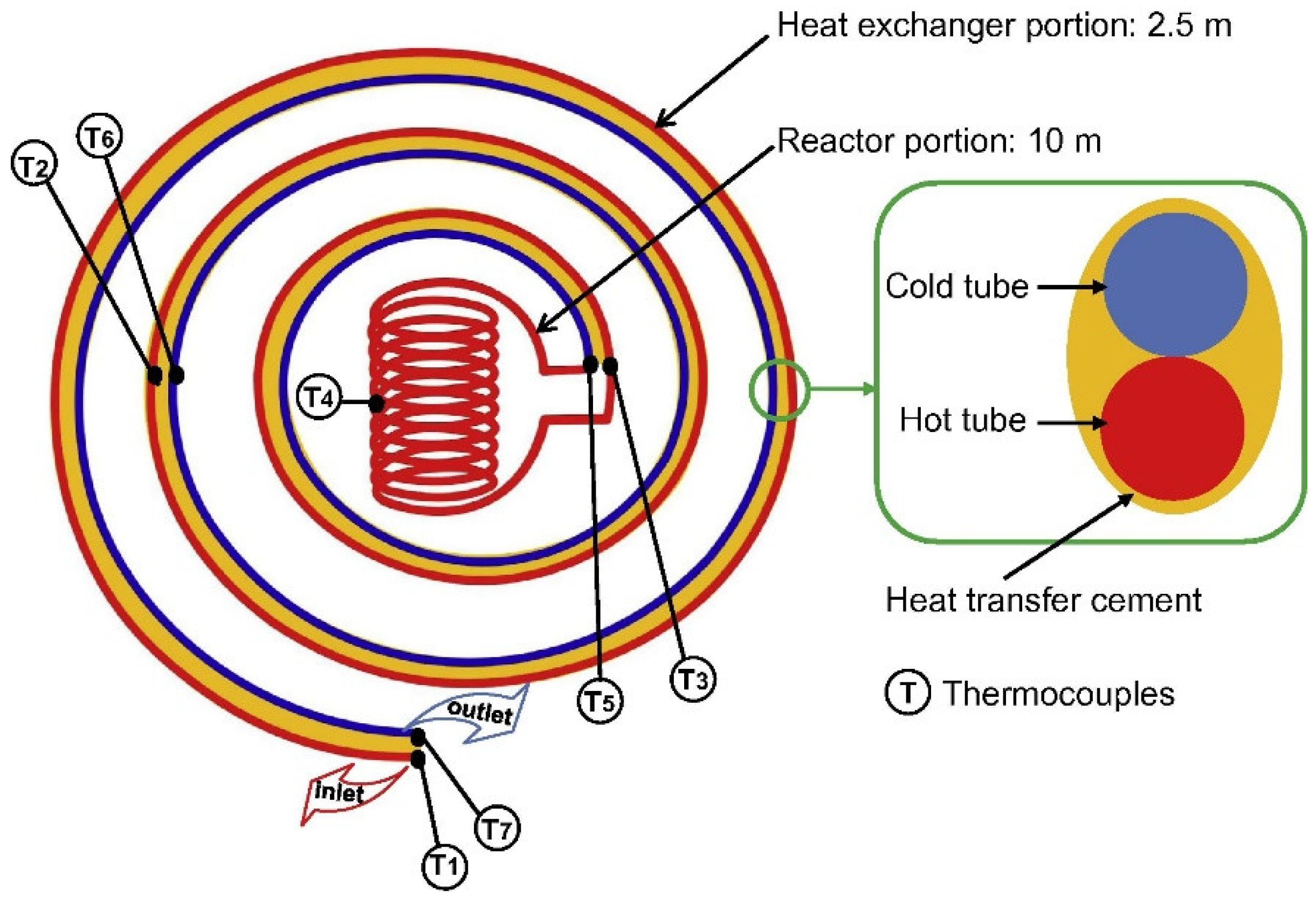
In the Matsumura group [68], a spiral reactor was developed and tested (Figure 3) proposing a similar heat exchanger design as a process unit more effective than the conventional shell-and-tube or plate-type heat exchanger. The good results with this spiral reactor were further explained by Yi et al. [69] when the concept was applied to the SCWG of methylhydrazine; they pointed out that in the spiral reactor the effective collision probability between reactants is higher than in a straight tube, because of the different proportion of water around the reactants in such a geometry. However, looking at their results, at least a 25% reactor length was needed to react the reaction temperature, so slow heating was not effectively avoided.
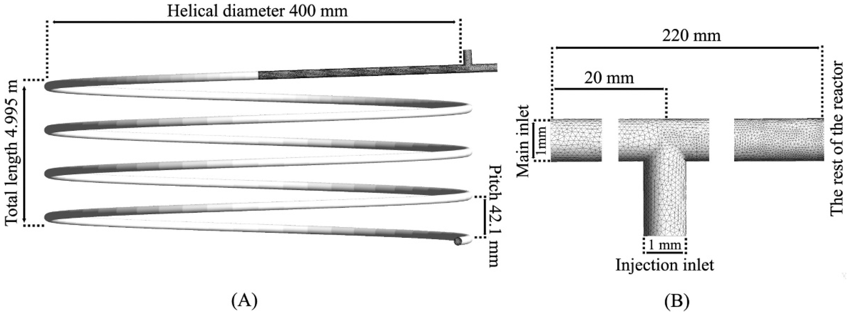
Another alternative consists of using a vertical or horizontal helically coiled tube, as proposed by different researchers. Thus, as pointed out by some researchers in the review by Vashisth et al. [70], vertical symmetric secondary flows appear due to buoyancy forces and, at the same time, horizontal symmetric secondary flows arise; these secondary flow structures make the mechanisms of heat transfer difficult, especially when considering changes in properties through the transition from subcritical to supercritical state conditions. Zhao et al. [71] simulated turbulent SCW flow in straight and helical tubes of 3.75 mm ID, which is a common diameter of laboratory tubes, using the SST k–ω model to obtain the effects of changes in properties, as well as buoyancy and centrifugal forces. They achieved that axial velocities are speeded up as a consequence of the decrease in density and the centrifugal forces, and hence, secondary flow becomes more and more intense, thus increasing velocity gradients in the core region. Likewise, above the pseudocritical point, the temperature profile in the core region flattens because of the maximum thermal conductivity, and the temperature distribution of the wall becomes more uniform. Yukananto et al. [72] performed a CFD modeling of glucose SCWG in a tubular helical reactor with an additional tube to inject the glucose stream with SCW coming through the helical tube (Figure 4). They obtained slow heating of the flow inside the injection tube due to recirculation in the tee fitting caused by the buoyancy forces. As a consequence, char is formed.
Li and Bai [73] performed another numerical study using the RNG k-ε model, assuming a constant heating flux for the inner coil and the outer coil adiabatic, analyzing the effect of specific heat, secondary flow velocity, and buoyancy. They found that the heat transfer coefficient (HTC) reaches a maximum before the pseudocritical point and decreases as the pressure increases under uniform heating, previously mentioned [51].
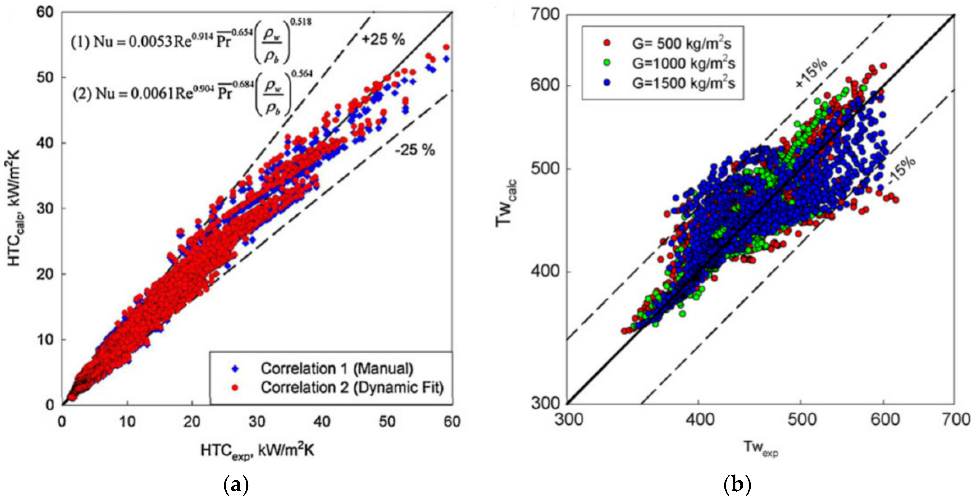
Regarding the HTC correlations for SCW, the one by Mokry et al. [74] has been widely used and discussed (Figure 5). Most of the HTC correlations have been developed on the basis of tests carried out in circular tubes with circumferential, uniform heating, which matches well with most of the experimental setups used in SCWG.
Another feasible way to solve this problem is the use of pieces in the input stream that cause a swirling motion in the flow, which contributes to obtain turbulence and residence time for the reaction, as already mentioned by Lester et al. [75] and also by other researchers.
The use of rifled or internally ribbed tubes heated uniformly or by one side has been examined and recently reviewed by Gu et al. [76], and summarized the enhancement of heat transfer in this type of geometrical configuration (Figure 6), mainly the higher area-to-volume ratio, the higher turbulence from the induced vortexes, the appearance of secondary and swirling flows due to the induced change in the fluid flow, and the continuous disturbance of the boundary layer that promotes better mixing.
Liang et al. [23] examined a way to try to increase the heating rate, using electromagnetic induction instead of resistance as a heating source in a first stage and an electric heating furnace to maintain the temperature. However, the basic problem related to resistance to heat transfer inside the reactor still remains with this type of heating.
In this regard, one more interesting option consists of using the principles of process intensification as an effective method to enhance heat transfer in the SCWG process, described in further detail in the next section.

4. Next Perspectives in Design

On the basis of the concept of a tubular reactor that may be extended to a multitube reactor, some ideas may be proposed and discussed to enhance heat transfer by designing involved process units.
There must be fast and effective heating inside the reactor, where fluid flows, and that is the zone where the highest resistance to heat transfer is found. In this way, a new reactor design could enhance this aspect. Here, process intensification may play an important role and there are a number of possibilities.
First, a nonmetallic reactor made of quartz could be used, for instance, instead of metallic alloys, such as Inconel 600 or 625, AISI 316, or different Hastelloy, along with microwave heating, where the frequency would be adjusted to selectively supply the energy required by the reactants to allow their molecules to overcome the activation energy, which is the energy barrier. This could be more efficient for the energy supply required for the reactions and even for the heating of all of the streams, which would take place more quickly and selectively. In fact, considering an Arrhenius-type kinetic law, heating must serve to increase the temperature term found in the exponential function. This heating way, against electric heating by resistances (directly disposed on the tube wall or applied externally to the reactor and transmitted by radiation), avoids temperature gradients that produce an energy distribution, and hence energy losses.
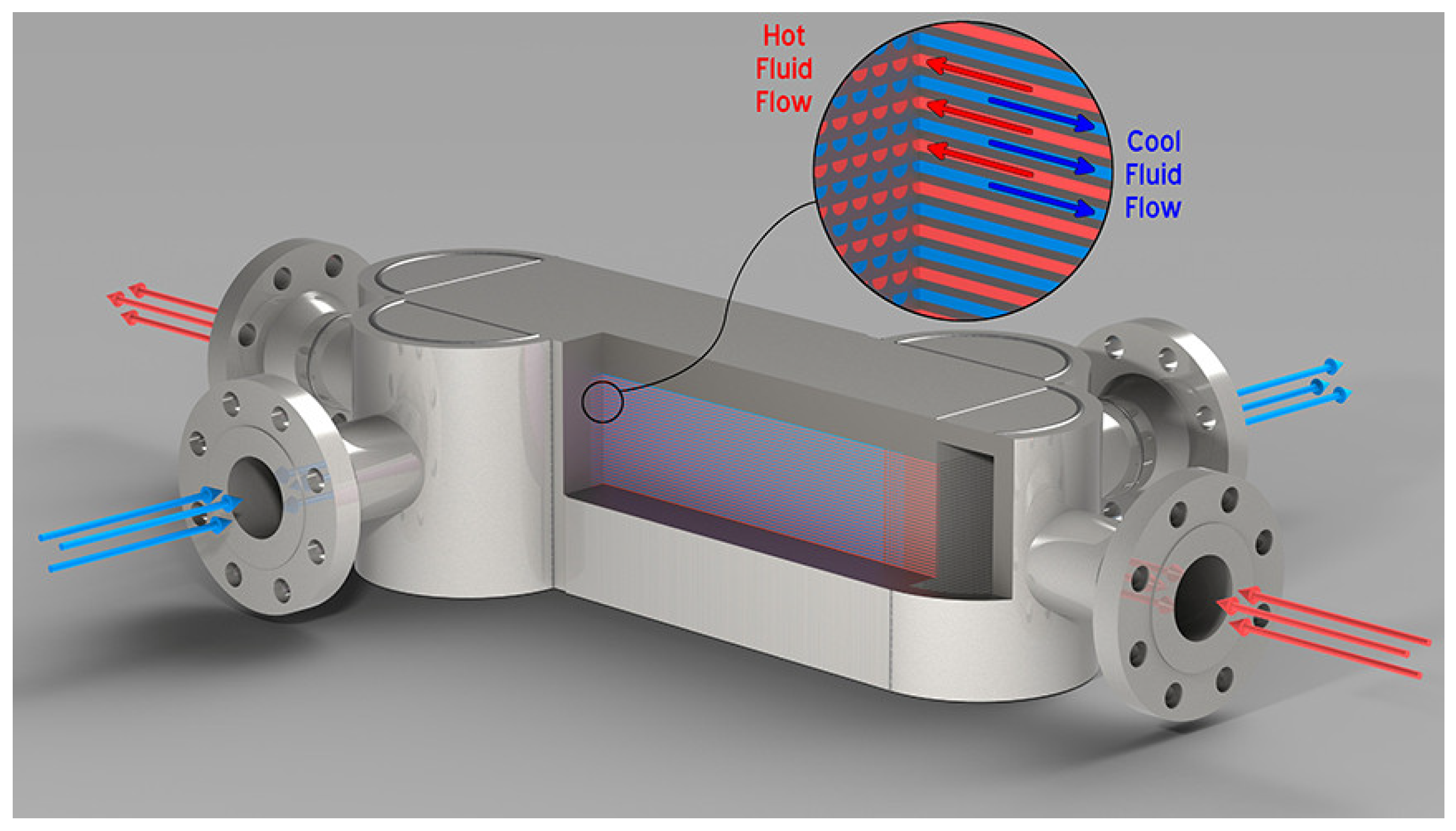
Second, a maximum specific surface area should be used to further improve mass and heat transfer. Thus, different and specific heat transfer equipment and reactors may be applied to achieve this target. The diffusion-bonded compact heat exchanger is a compact type heat changer that can operate up to 100 MPa or 900 °C, reducing up to 90% of the area compared to multitube heat exchangers, where the heat transfer area per unit volume is at least 1000 m2/m3, so the size can be reduced to 85% compared to conventional multitube heat transfer [77]. This heat exchanger could be used as both a microreactor and a microheat exchanger. Mortean et al. [78] evaluated heat transfer in a diffusion-bonded compact heat exchanger at low flow rates for low Reynolds numbers, mainly in the laminar flow regime, and more recently Sarmiento et al. [79] extended the study in a series of Reynolds numbers between 2600 and 7500, thus covering the transition to a turbulent flow regime. Currently, there are already several manufacturers [80,81], and Figure 7 shows the details of one of them.
Likewise, microchannel reactors show a surface-to-volume ratio much larger than that of multitube reactors, which could be the logical selection for scaling up as tubes may be multiplied as the flow rate does, especially considering that the lower thickness of small ID tubes has mechanical resistance similar to that of tubes with larger ID and thickness under the severe conditions of SWG. The use of microreactors with thousands of microchannels allows for good mixing of reactants and the removal of heat is more efficient. There is another possibility of a micro reactor plus a micro heat exchanger.
Regarding heat transfer in lab-scale tests, apart from using a different energy source, the use of compact devices, such as those mentioned above, could allow for better heat transfer performance using flue gas coming from a burner at high temperature acting as the hot fluid. In addition, the design of a series of heat exchangers should be performed, especially the one where the transition from subcritical to supercritical state takes place because of the strong change in the physical properties of the feed, mainly wet biomass with a high proportion of water.
Furthermore, the use of static mixers promotes turbulence without mobile parts and presents resistance to interphase mass transfer that is noticeably smaller than in conventional equipment, such as stirred tanks, and the flow pattern is close to the plug flow and is more uniform, and the residence time of the molecules is closely distributed. As a consequence, the collisions of molecules will be more effective and energy losses will be lessened [82].
It is clear that despite the proposed devices being real, further research must be carried out to improve their performance and applicability and, in particular, to reduce capital costs so that they may be used at full scale.

5. Conclusions

In this short review, the shortcomings found in the SCWG experimental facilities and heat transfer limitations are described, and the main causes are analyzed. The low flow rate in lab-scale reactors leads to deterioration in heat transfer because the fluid velocity is quite low and so turbulence is almost nonexistent. As a consequence, the probability of forming char and tar is higher than if a better heat transfer took place. Beyond the inlet zone of the reactor, the transition from subcritical to supercritical fluid state involves a drastic change in physical properties, although the flow regime is too low to achieve effective turbulent mixing. Similarly, a series of troubleshooting options are proposed to overcome the limitations of heat transfer, such as using two streams, one containing the organic load and the other containing only water, a spiral reactor as well as a vertical or horizontal helically coiled tube, and also the use of pieces in the input stream that cause a swirling motion in the flow. Despite all these attempts, the basic problem related to resistance to heat transfer inside the reactor still remains with this type of heating, which is essentially slow, at least in some part of the reactor. In this regard, several options with respect to new perspectives in equipment design are described as different proposals to improve experimental studies, based on the intensification process. Among these, we propose the use of static mixers, a different way to heat the feed entering the reactor, and the reactor design and heat exchangers, which could be integrated into a unique equipment. To advance the technology from the lab scale, new experiments should be carried out in facilities that include both conventional and new process units, to compare the process performance using these experiments or the others, while keeping the remaining operating conditions for comparison. Nevertheless, regardless of the results of these new experiments, all previous experimental studies with the described limitations are useful, enabling increased knowledge and understanding of different phenomena, which can be applied in future development of the technology.

Author Contributions

F.J.G.O.: Conceptualization, methodology, formal analysis, resources, writing—original draft preparation, writing—review and editing, supervision, project administration, funding acquisition. F.L.-G.: Resources, methodology, writing—review and editing. F.J.J.-E.: Writing—review and editing, supervision, funding acquisition. J.M.B.: Resources, writing—review and editing. All authors have read and agreed to the published version of the manuscript.

Funding

This research was funded by the Consejería de Economía y Conocimiento (Junta de Andalucía) for the financial support of his PAIDI 2020 Research Project coded as P18-RT-2521).

Institutional Review Board Statement

Not applicable.

Informed Consent Statement

Not applicable.

Data Availability Statement

References.

Conflicts of Interest

The authors declare no conflict of interest.

References

  1. Savage, P.E. Organic Chemical Reactions in Supercritical Water. Chem. Rev. 1999, 99, 603–621. [Google Scholar] [CrossRef]
  2. Matsumura, Y.; Minowa, T.; Potic, B.; Kersten, S.R.A.; Prins, W.; Van Swaaij, W.P.M.; Van De Beld, B.; Elliott, D.C.; Neuenschwander, G.G.; Kruse, A.; et al. Biomass gasification in near- and super-critical water: Status and prospects. Biomass Bioenergy 2005, 29, 269–292. [Google Scholar] [CrossRef]
  3. Kruse, A. Supercritical water gasification. Biofuels Bioprod. Biorefin. 2008, 2, 415–437. [Google Scholar] [CrossRef]
  4. Fan, C.; Jin, H. A numerical study on gasification of a single char particle in supercritical water for hydrogen production. Fuel 2020, 268, 117399. [Google Scholar] [CrossRef]
  5. Wen, Q.L.; Gu, H.Y. Numerical simulation of heat transfer deterioration phenomenon in supercritical water through vertical tube. Ann. Nucl. Energy 2010, 37, 1272–1280. [Google Scholar] [CrossRef]
  6. Gutiérrez Ortiz, F.J.; Kruse, A. The use of process simulation in supercritical fluids applications. React. Chem. Eng. 2020, 5, 424–451. [Google Scholar] [CrossRef]
  7. Pinkard, B.R.; Gorman, D.J.; Tiwari, K.; Kramlich, J.C.; Reinhall, P.G.; Novosselov, I.V. Review of Gasification of Organic Compounds in Continuous-Flow, Supercritical Water Reactors. Ind. Eng. Chem. Res. 2018, 57, 3471–3481. [Google Scholar] [CrossRef]
  8. Rodriguez Correa, C.; Kruse, A. Supercritical water gasification of biomass for hydrogen production—Review. J. Supercrit. Fluids 2018, 133, 573–590. [Google Scholar] [CrossRef]
  9. Ferreira-Pinto, L.; Silva Parizi, M.P.; de Araújo, P.C.C.S.; Zanette, A.F.; Cardozo-Filho, L. Experimental basic factors in the production of H2 via supercritical water gasification. Int. J. Hydrogen Energy 2019, 44, 25365–25383. [Google Scholar] [CrossRef]
  10. Ibrahim, A.B.A.; Akilli, H. Supercritical water gasification of wastewater sludge for hydrogen production. Int. J. Hydrogen Energy 2019, 44, 10328–10349. [Google Scholar] [CrossRef]
  11. Zhang, Y.; Li, L.; Xu, P.; Liu, B.; Shuai, Y.; Li, B. Hydrogen production through biomass gasification in supercritical water: A review from exergy aspect. Int. J. Hydrogen Energy 2019, 44, 15727–15736. [Google Scholar] [CrossRef]
  12. Hu, Y.; Gong, M.; Xing, X.; Wang, H.; Zeng, Y.; Xu, C.C. Supercritical water gasification of biomass model compounds: A review. Renew. Sustain. Energy Rev. 2020, 118, 12–14. [Google Scholar] [CrossRef]
  13. Gutiérrez Ortiz, F.J. Techno-economic assessment of supercritical processes for biofuel production. J. Supercrit. Fluids 2020, 160, 104788. [Google Scholar] [CrossRef]
  14. Abdpour, S.; Santos, R.M. Recent advances in heterogeneous catalysis for supercritical water oxidation/gasification processes: Insight into catalyst development. Process Saf. Environ. Prot. 2021, 149, 169–184. [Google Scholar] [CrossRef]
  15. Farobie, O.; Matsumura, Y.; Syaftika, N.; Amrullah, A.; Hartulistiyoso, E.; Bayu, A.; Moheimani, N.R.; Karnjanakom, S.; Saefurahman, G. Recent advancement on hydrogen production from macroalgae via supercritical water gasification. Bioresour. Technol. Rep. 2021, 16, 100844. [Google Scholar] [CrossRef]
  16. Lee, C.S.; Conradie, A.V.; Lester, E. Review of supercritical water gasification with lignocellulosic real biomass as the feedstocks: Process parameters, biomass composition, catalyst development, reactor design and its challenges. Chem. Eng. J. 2021, 415, 128837. [Google Scholar] [CrossRef]
  17. Okolie, J.A.; Epelle, E.I.; Nanda, S.; Castello, D.; Dalai, A.K.; Kozinski, J.A. Hydrogen Production: A Comprehensive Review. J. Supercrit. Fluids 2021, 173, 105199. [Google Scholar] [CrossRef]
  18. Matsumura, Y.; Minowa, T. Fundamental design of a continuous biomass gasification process using a supercritical water fluidized bed. Int. J. Hydrogen Energy 2004, 29, 701–707. [Google Scholar] [CrossRef]
  19. Müller, J.B.; Vogel, F. Tar and coke formation during hydrothermal processing of glycerol and glucose. Influence of temperature, residence time and feed concentration. J. Supercrit. Fluids 2012, 70, 126–136. [Google Scholar] [CrossRef]
  20. Lu, Y.; Zhang, T.; Dong, X. Bed to wall heat transfer in supercritical water fluidized bed: Comparison with the gas-solid fluidized bed. Appl. Therm. Eng. 2014, 88, 297–305. [Google Scholar] [CrossRef]
  21. Zhang, T.; Lu, Y.; Yao, L. Experimental study of wall-to-bed heat transfer in a supercritical water fluidized bed. Int. J. Multiph. Flow 2018, 109, 26–34. [Google Scholar] [CrossRef]
  22. Wu, Z.; Ren, Y.; Ou, G.; Jin, H. Influence of special water properties variation on the heat transfer of supercritical water flow around a sphere. Chem. Eng. Sci. 2020, 222, 115698. [Google Scholar] [CrossRef]
  23. Liang, X.; Zhao, Q.; Dong, Y.; Guo, L.; Jin, Z.; Liu, Q. Experimental investigation on supercritical water gasification of organic-rich shale with low maturity for syngas production. Energy Fuels 2021, 35, 7657–7665. [Google Scholar] [CrossRef]
  24. Sinag, A.; Kruse, A.; Maniam, P. Hydrothermal conversion of biomass and different model compounds. J. Supercrit. Fluids 2012, 71, 80–85. [Google Scholar] [CrossRef]
  25. Chen, Y.; Guo, L.; Jin, H.; Yin, J.; Lu, Y.; Zhang, X. An experimental investigation of sewage sludge gasification in near and super-critical water using a batch reactor. Int. J. Hydrogen Energy 2013, 38, 12912–12920. [Google Scholar] [CrossRef]
  26. Castello, D.; Rolli, B.; Kruse, A.; Fiori, L. Supercritical water gasification of biomass in a ceramic reactor: Long-time batch experiments. Energies 2017, 10, 1734. [Google Scholar] [CrossRef] [Green Version]
  27. Graz, Y.; Bostyn, S.; Richard, T.; Bocanegra, P.E.; De Bilbao, E.; Poirier, J.; Gokalp, I. Hydrothermal conversion of Ulva macro algae in supercritical water. J. Supercrit. Fluids 2016, 107, 182–188. [Google Scholar] [CrossRef]
  28. Weijin, G.; Zizheng, Z.; Yue, L.; Qingyu, W.; Lina, G. Hydrogen production and phosphorus recovery via supercritical water gasification of sewage sludge in a batch reactor. Waste Manag. 2019, 96, 198–205. [Google Scholar] [CrossRef] [PubMed]
  29. Demirel, E.; Erkey, C.; Ayas, N. Supercritical water gasification of fruit pulp for hydrogen production: Effect of reaction parameters. J. Supercrit. Fluids 2021, 177, 105329. [Google Scholar] [CrossRef]
  30. Weiss-Hortala, E.; Kruse, A.; Ceccarelli, C.; Barna, R. Influence of phenol on glucose degradation during supercritical water gasification. J. Supercrit. Fluids 2010, 53, 42–47. [Google Scholar] [CrossRef]
  31. Goodwin, A.K.; Rorrer, G.L. Reaction rates for supercritical water gasification of xylose in a micro-tubular reactor. Chem. Eng. J. 2010, 163, 10–21. [Google Scholar] [CrossRef]
  32. Zhang, L.; Champagne, P.; Xu, C.C. Supercritical water gasification of an aqueous by-product from biomass hydrothermal liquefaction with novel Ru modified Ni catalysts. Bioresour. Technol. 2011, 102, 8279–8287. [Google Scholar] [CrossRef] [PubMed]
  33. Gutiérrez Ortiz, F.J.; Serrera, A.; Galera, S.; Ollero, P. Experimental study of the supercritical water reforming of glycerol without the addition of a catalyst. Energy 2013, 56, 193–206. [Google Scholar] [CrossRef]
  34. Castello, D.; Kruse, A.; Fiori, L. Low temperature supercritical water gasification of biomass constituents: Glucose/phenol mixtures. Biomass Bioenergy 2015, 73, 84–94. [Google Scholar] [CrossRef]
  35. Nanda, S.; Reddy, S.N.; Hunter, H.N.; Dalai, A.K.; Kozinski, J.A. Supercritical water gasification of fructose as a model compound for waste fruits and vegetables. J. Supercrit. Fluids 2015, 104, 112–121. [Google Scholar] [CrossRef]
  36. Ferreira-Pinto, L.; Feirhrmann, A.C.; Corazza, M.L.; Fernandes-Machado, N.R.C.; Dos Reis Coimbra, J.S.; Saldaña, M.D.A.; Cardozo-Filho, L. Hydrogen production and TOC reduction from gasification of lactose by supercritical water. Int. J. Hydrogen Energy 2015, 40, 12162–12168. [Google Scholar] [CrossRef]
  37. Gutiérrez Ortiz, F.J.; Campanario, F.J.; Ollero, P. Supercritical water reforming of model compounds of bio-oil aqueous phase: Acetic acid, acetol, butanol and glucose. Chem. Eng. J. 2016, 298, 243–258. [Google Scholar] [CrossRef]
  38. Adar, E.; Ince, M.; Bilgili, M.S. Supercritical water gasification of sewage sludge by continuous flow tubular reactor: A pilot scale study. Chem. Eng. J. 2020, 391, 123499. [Google Scholar] [CrossRef]
  39. Bergmann, C.M.; Ormiston, S.J.; Chatoorgoon, V. Comparative study of turbulence model predictions of upward supercritical fluid flow in vertical rod bundle subchannels. Nucl. Eng. Des. 2017, 322, 177–191. [Google Scholar] [CrossRef]
  40. Jaromin, M.; Anglart, H. A numerical study of heat transfer to supercritical water flowing upward in vertical tubes under normal and deteriorated conditions. Nucl. Eng. Des. 2013, 264, 61–70. [Google Scholar] [CrossRef]
  41. Shang, Z.; Chen, S. Numerical investigation of diameter effect on heat transfer of supercritical water flows in horizontal round tubes. Appl. Therm. Eng. 2011, 31, 573–581. [Google Scholar] [CrossRef] [Green Version]
  42. Huang, X.; Wang, Q.; Song, Z.; Yin, Y.; Wang, H. Heat transfer characteristics of supercritical water in horizontal double-pipe. Appl. Therm. Eng. 2020, 173, 115191. [Google Scholar] [CrossRef]
  43. El-Morshedy, S.E.D.; Ibrahim, S.M.A.; Alyan, A.; Abdelmaksoud, A. Heat transfer deterioration mechanism for water at supercritical pressure. Int. J. Thermofluids 2020, 7–8, 100020. [Google Scholar] [CrossRef]
  44. Gao, Z.; Bai, J. Numerical analysis on nonuniform heat transfer of supercritical pressure water in horizontal circular tube. Appl. Therm. Eng. 2017, 120, 10–18. [Google Scholar] [CrossRef]
  45. Liu, L.; Xiao, Z.; Yan, X.; Zeng, X.; Huang, Y. Heat transfer deterioration to supercritical water in circular tube and annular channel. Nucl. Eng. Des. 2013, 255, 97–104. [Google Scholar] [CrossRef]
  46. Dongliang, M.; Tao, Z.; Bing, L.; Ali Shahzad, M.; Yanping, H. An improved correlation on the onset of heat transfer deterioration in supercritical water. Nucl. Eng. Des. 2018, 326, 290–300. [Google Scholar] [CrossRef]
  47. Xie, J.; Yan, H.; Sundén, B.; Xie, G. A numerical prediction on heat transfer characteristics from a circular tube in supercritical fluid crossflow. Appl. Therm. Eng. 2019, 153, 692–703. [Google Scholar] [CrossRef]
  48. Wang, Z.; Qi, G.; Li, M. Numerical investigation of heat transfer to supercritical water in vertical tube under semicircular heating condition. Energies 2019, 12, 3958. [Google Scholar] [CrossRef] [Green Version]
  49. Zhang, L.; Cai, B.; Weng, Y.; Gu, H.; Wang, H.; Li, H.; Chatoorgoon, V. Experimental investigations on flow characteristics of two parallel channels in a forced circulation loop with supercritical water. Appl. Therm. Eng. 2016, 106, 98–108. [Google Scholar] [CrossRef]
  50. Basu, P.; Mettanant, V. Biomass Gasification in Supercritical Water—A Review. Int. J. Chem. React. Eng. 2009, 7. [Google Scholar] [CrossRef]
  51. Odu, S.O.; Koster, P.; Van Der Ham, A.G.J.; Van Der Hoef, M.A.; Kersten, S.R.A. Heat Transfer to Sub- and Supercritical Water Flowing Upward in a Vertical Tube at Low Mass Fluxes: Numerical Analysis and Experimental Validation. Ind. Eng. Chem. Res. 2016, 55, 13120–13131. [Google Scholar] [CrossRef]
  52. Kawasaki, S.I.; Sue, K.; Ookawara, R.; Wakashima, Y.; Suzuki, A.; Hakuta, Y.; Arai, K. Engineering study of continuous supercritical hydrothermal method using a T-shaped mixer: Experimental synthesis of NiO nanoparticles and CFD simulation. J. Supercrit. Fluids 2010, 54, 96–102. [Google Scholar] [CrossRef]
  53. Qu, M.; Yang, D.; Liang, Z.; Wan, L.; Liu, D. Experimental and numerical investigation on heat transfer of ultra-supercritical water in vertical upward tube under uniform and non-uniform heating. Int. J. Heat Mass Transf. 2018, 127, 769–783. [Google Scholar] [CrossRef]
  54. Lee, I.G.; Kim, M.S.; Ihm, S.K. Gasification of glucose in supercritical water. Ind. Eng. Chem. Res. 2002, 41, 1182–1188. [Google Scholar] [CrossRef]
  55. May, A.; Salvadó, J.; Torras, C.; Montané, D. Catalytic gasification of glycerol in supercritical water. Chem. Eng. J. 2010, 160, 751–759. [Google Scholar] [CrossRef] [Green Version]
  56. Susanti, R.F.; Nugroho, A.; Lee, J.; Kim, Y.; Kim, J. Noncatalytic gasification of isooctane in supercritical water: A Strategy for high-yield hydrogen production. Int. J. Hydrogen Energy 2011, 36, 3895–3906. [Google Scholar] [CrossRef]
  57. Tushar, M.S.H.K.; Dutta, A.; Xu, C.C. Catalytic supercritical gasification of biocrude from hydrothermal liquefaction of cattle manure. Appl. Catal. B Environ. 2016, 189, 119–132. [Google Scholar] [CrossRef]
  58. Kumabe, K.; Itoh, N.; Matsumoto, K.; Hasegawa, T. Hydrothermal gasification of glucose and starch in a batch and continuous reactor. Energy Rep. 2017, 3, 70–75. [Google Scholar] [CrossRef]
  59. Amrullah, A.; Matsumura, Y. Supercritical water gasification of sewage sludge in continuous reactor. Bioresour. Technol. 2018, 249, 276–283. [Google Scholar] [CrossRef] [PubMed]
  60. Purkarová, E.; Ciahotný, K.; Šváb, M.; Skoblia, S.; Beňo, Z. Supercritical water gasification of wastes from the paper industry. J. Supercrit. Fluids 2018, 135, 130–136. [Google Scholar] [CrossRef]
  61. Mylapilli, S.V.P.; Reddy, S.N. Catalytic and non-catalytic degradation of acetaminophen in supercritical water. Environ. Res. 2021, 7, 112191. [Google Scholar] [CrossRef] [PubMed]
  62. Hendry, D.; Venkitasamy, C.; Wilkinson, N.; Jacoby, W. Exploration of the effect of process variables on the production of high-value fuel gas from glucose via supercritical water gasification. Bioresour. Technol. 2011, 102, 3480–3487. [Google Scholar] [CrossRef] [PubMed]
  63. Cantero, D.A.; Álvarez, A.; Bermejo, M.D.; Cocero, M.J. Transformation of glucose into added value compounds in a hydrothermal reaction media. J. Supercrit. Fluids 2015, 98, 204–210. [Google Scholar] [CrossRef]
  64. Sierra-Pallares, J.; Huddle, T.; Alonso, E.; Mato, F.A.; García-Serna, J.; Cocero, M.J.; Lester, E. Prediction of residence time distributions in supercritical hydrothermal reactors working at low Reynolds numbers. Chem. Eng. J. 2016, 299, 373–385. [Google Scholar] [CrossRef]
  65. Vaquerizo, L.; Cocero, M.J. Ultrafast heating by high efficient biomass direct mixing with supercritical water. Chem. Eng. J. 2019, 378, 122199. [Google Scholar] [CrossRef]
  66. Yukananto, R.; Pozarlik, A.K.; Brem, G. Computational fluid dynamic model for glycerol gasification in supercritical water in a tee junction shaped cylindrical reactor. J. Supercrit. Fluids 2018, 133, 330–342. [Google Scholar] [CrossRef]
  67. Guo, S.; Guo, L.; Cao, C.; Yin, J.; Lu, Y.; Zhang, X. Hydrogen production from glycerol by supercritical water gasification in a continuous flow tubular reactor. Int. J. Hydrogen Energy 2012, 37, 5559–5568. [Google Scholar] [CrossRef]
  68. Farobie, O.; Sasanami, K.; Matsumura, Y. A novel spiral reactor for biodiesel production in supercritical ethanol. Appl. Energy 2015, 147, 20–29. [Google Scholar] [CrossRef]
  69. Yi, L.; Wang, L.; Guo, L.; Cheng, K.; Jin, H.; Chen, Y.; Cao, W. Hydrogen production by supercritical water gasification of methylhydrazine in continuous system. J. Water Process Eng. 2021, 42, 102037. [Google Scholar] [CrossRef]
  70. Vashisth, S.; Kumar, V.; Nigam, K.D.P. A review on the potential applications of curved geometries in process industry. Ind. Eng. Chem. Res. 2008, 47, 3291–3337. [Google Scholar] [CrossRef]
  71. Zhao, H.; Li, X.; Wu, X. Transfer Characteristics in Vertical Helical Tubes. J. Supercrit. Fluids 2017, 127, 48–61. [Google Scholar] [CrossRef]
  72. Yukananto, R.; Pozarlik, A.; Bramer, E.; Brem, G. Numerical modelling of char formation during glucose gasification in supercritical water. J. Supercrit. Fluids 2018, 140, 258–269. [Google Scholar] [CrossRef]
  73. Li, F.; Bai, B. Flow and heat transfer of supercritical water in the vertical helically-coiled tube under half-side heating condition. Appl. Therm. Eng. 2018, 133, 512–519. [Google Scholar] [CrossRef]
  74. Mokry, S.; Pioro, I.; Farah, A.; King, K.; Gupta, S.; Peiman, W.; Kirillov, P. Development of supercritical water heat-transfer correlation for vertical bare tubes. Nucl. Eng. Des. 2011, 241, 1126–1136. [Google Scholar] [CrossRef]
  75. Lester, E.; Blood, P.; Denyer, J.; Giddings, D.; Azzopardi, B.; Poliakoff, M. Reaction engineering: The supercritical water hydrothermal synthesis of nano-particles. J. Supercrit. Fluids 2006, 37, 209–214. [Google Scholar] [CrossRef]
  76. Gu, J.; Zhang, Y.; Wu, Y.; Li, Z.; Tang, G.; Wang, Q.; Lyu, J. Numerical study of flow and heat transfer of supercritical water in rifled tubes heated by one side. Appl. Therm. Eng. 2018, 142, 610–621. [Google Scholar] [CrossRef]
  77. Miwa, Y.; Noishiki, K.; Suzuki, T.; Takatsuki, K. Research and Development Kobe Steel Engineering Reports; Kobe Steel Ltd.: Kobe, Japan, 2013; pp. 23–27. [Google Scholar]
  78. Mortean, M.V.V.; Cisterna, L.H.R.; Paiva, K.V.; Mantelli, M.B.H. Development of diffusion welded compact heat exchanger technology. Appl. Therm. Eng. 2016, 93, 995–1005. [Google Scholar] [CrossRef]
  79. Sarmiento, A.P.C.; Soares, V.H.T.; Carqueja, G.G.; Batista, J.V.C.; Milanese, F.H.; Mantelli, M.B.H. Thermal performance of diffusion-bonded compact heat exchangers. Int. J. Therm. Sci. 2020, 153, 106384. [Google Scholar] [CrossRef]
  80. Vacuum Process Engineering Diffusion Bonded Microchannel Heat Exchangers. Available online: https://www.vpei.com/diffusion-bonded-microchannel-heat-exchangers/ (accessed on 9 November 2021).
  81. Kobe Steel Ltd. Diffusion Bonded Compact Heat Exchanger. Available online: https://www.kobelco.co.jp/english/products/ecmachinery/dche/files/Microchannel_dche_smcr_brochure.pdf (accessed on 9 November 2021).
  82. Stankiewicz, A.; Moulijn, J. Re-Engineering the Chemical Processing Plant. Process Intensification; Marcel Dekker, Inc.: New York, NY, USA, 2004; ISBN 0824743024. [Google Scholar]
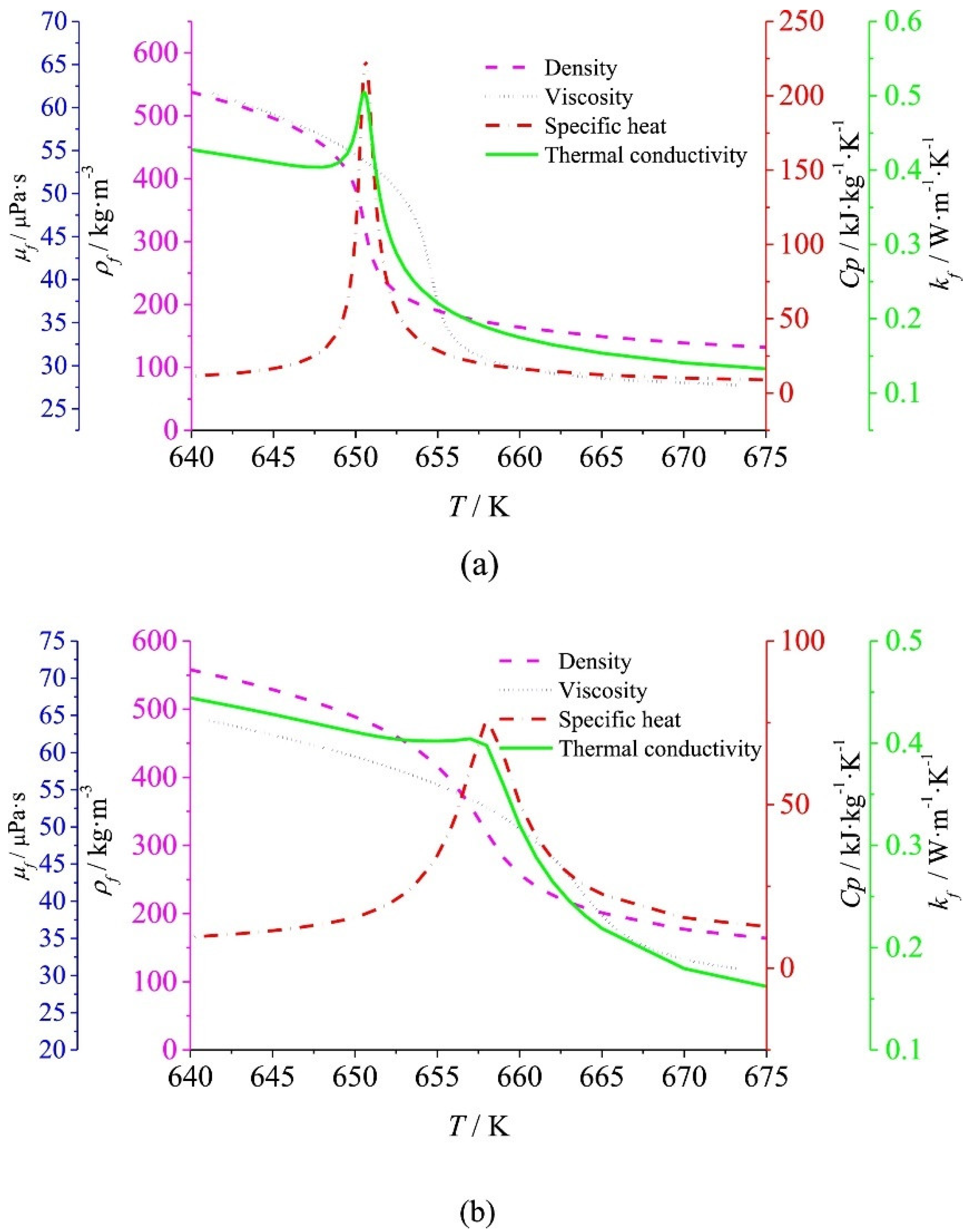
Figure 1. Physical properties of water near the critical point at (a) 23 MPa and (b) 25 MPa [21]. Reprint with permission from ref. [21]. Copyright 2018 Elsevier.
Energies 15 00177 g001
Figure 2. Tee fitting and injection zone [66]. Reprint with permission from ref. [66]. Copyright 2017 Elsevier.
Energies 15 00177 g002
Figure 3. Spiral reactor [68]. Reprint with permission from ref. [68]. Copyright 2015 Elsevier.
Energies 15 00177 g003
Figure 4. Scheme of the helical reactor (A) and the injector tube (B) [72]. Reprint with permission from ref. [72]. Copyright 2018 Elsevier.
Energies 15 00177 g004
Figure 5. Comparison of the fit of the data with the experimental data: (a) for HTC and (b) for wall temperature [74]; superficial mass flow rates at lab are usually lower than those tested in this Figure. Reprint with permission from ref. [74]. Copyright 2010 Elsevier.
Energies 15 00177 g005
Figure 6. Physical structure of the rifled tube [76]. Reprint with permission from ref. [76]. Copyright 2018 Elsevier.
Energies 15 00177 g006
Figure 7. Diffusion-bonded microchannel heat exchanger [80].
Energies 15 00177 g007
Publisher’s Note: MDPI stays neutral with regard to jurisdictional claims in published maps and institutional affiliations.