Abstract
Metal halide perovskite solar cells (PSCs) are considered an effectual way to enhance photovoltaic (PV) properties, leading to low-cost and high efficiency. PSCs have experienced rapid improvement in the last ten years. The device’s energy production increases extensively in the presence of concentrated light. The use of concentrated optics in solar cells has spurred the PV industry towards tremendous research. Incorporating the concentrated optic into the PV system as a concentrated PV (CPV) means it can capture light effectively and operate at increased efficiencies under concentrated irradiance. This work addresses an initial assessment of the power conversion efficiency (PCE) enhancement of the ambient PSCs by externally integrating concentrated optics. Significantly, the concentrated optics exhibit ~90% of the PCE enhancement under the solar irradiance of 400 W/m2, whereas 16% of the PCE increase was observed when the solar irradiance changed to 1000 W/m2. During optics integration, a considerable elevation of short-circuit current predominately facilitated the overall efficiency enhancement of the PSC. A systematic PV parameters effect on the optic integration on PSCs was further scrutinized. Therefore, this work signifies a possible way to alleviate the PCE of carbon-based PSC using concentrated optics. This work focuses on integrating CPVs into PSCs, preventing PSC stability and scalability issues, with light conditioning techniques.
1. Introduction
The rapid cutback in the manufacturing cost of the module set balances installation and system costs, making it a game-changer to produce electricity for residential and utility purposes. Photovoltaic based on metal halide perovskite solar cells have stimulated a rapid rise over the last few years to two remarkable improvements in power conversion efficiency: from 3.8% to a certified value of 22%. The exceptional characteristics of perovskite solar cells (PSCs), such as their high absorption coefficient [1,2], direct tunable bandgap [3,4,5], and low-temperature solution processability [6], prompt interest in the PSC research community. Moreover, some additional properties, such as long diffusion length, low exciton binding energy, and low non-radiative carrier recombination, make PSCs more interesting for photovoltaic applications [7,8]. Finally, the introduction of novel device architecture optimization of each functional layer’s interfacial characteristics and controlled morphology have increased PSC’s output. These advances have promoted the PSC industry by contributing further research toward exploring more intriguing aspects of the photovoltaic (PV) field.
The PSC’s device architecture usually consists of electron transport material, a light-absorbing layer, and hole transport material. Some other functional layers, to enhance the recombination process, stability, and overall PSC performance, are evident. The extraction of photo-generated charges from the light-absorbing layer and transportation to the electrode is electron transport and hole transport layers. The fabrication process and selection of material for different layers also play a crucial role in the PSC’s better performance. The mesoporous-based PSC is evident in overcoming issues due to its repellent behaviour against environmental factors, high energy conversion, and fabrication ease. The use of carbon back contact as a substitute for gold, with its high conductivity, cost-efficiency and low-temperature processing, may make it suitable for achieving decent power conversion efficiency (PCE).
The fundamental issues that need attention to allow for competition with silicon solar cells and other commercial alternatives are PSC stability and resistance from environmental factors such as moisture, low toxicity, a long lifetime, a stable fabrication process, and the system’s upscaling. Furthermore, the organic materials can migrate when exposed to sunlight or high temperature, resulting in the PSC system’s degradation [9]. However, superior perovskite films with a good crystal structure, fine surface morphology, low degradation of organic material, and few defects could improve the photovoltaic solar cells’ stability and performance.
Experts have explored different routes to overcome these barriers and understand the working mechanisms and modifications of perovskite films to halt and prevent degradation, instability and other related obstacles from holding back PSCs from commercialization. Different strategies such as doping appropriate materials, double perovskite, a suitable fabrication process, and interface layers are on focus to flag up PSCs to the PV industry forefront. Furthermore, mixed halide engineering has been represented as an effective way to enhance PSC’s optoelectronic properties by exceeding ~20% efficiency [10,11].
An additional promising direction uses cation substitute to successfully incorporate mixed halide to improve the perovskite material. Implementing the non-toxic HTL and ETL used in perovskite is reported to lead to high power conversion efficiency and stability [12]. Transport properties of material electron and hole mobility and extraction are the focal points to achieving PSC high efficiency. Simultaneously, long-term stability, cost, and easy processability still need to be considered. Another strategy that seeks to enhance the electronic structure and optical behaviour for numerous optoelectronic applications is the emergence of non-toxic stable halide double perovskite [13].
The increase in PCE and PSC stability has moved more into the focus of the researcher. Still, a versatile approach that has not received enough attention is concentrated light for PSCs. It is surprising that this concept has little consideration in PSCs. A possible reason could be the requirement of enhanced absorber material, which requires a higher demand for stability and includes sufficiently low charge carrier recombination rates. The concentrated photovoltaic (CPV) is an agnostic technology that generates electricity more efficiently by utilizing mirrors or lenses as a concentrated optic to focus sunlight onto a small area, unlike the traditional PV systems [14]. Even a CPC system comprises of a larger acceptance angle and higher optical efficiency compared to the mirror CPC. CPV technology is quite efficient, cost-effective and more environmentally friendly than standard flat plate PVs. The highest reported PCE for planner perovskite solar cells was 25.2% [15]. That is for small-sized cells in an active area of a few mm2. Increasing the demand for a cm2 area pushed the PCE to near 20% [16]. As the active area is enlarged further, the PCE drops rapidly, mainly due to inefficient film deposition with pores, grain boundaries, and increased resistance of the transparent conducting oxide, etc. [4]. A larger cell area also increases the probability of moisture-induced degradation from the larger contact surface. Appropriate encapsulation can be beneficial, but that adds extra cost to the complete module.
On the other hand, scalability problems can be addressed with light conditioning techniques like CPV. This technique is not new, but it failed to compete with flat plate solar cells on economic grounds. Applying the refractive and reflective principles of optics, the optical component concentrates the incoming sunlight, which further magnifies energy repeatedly. The possible reason for this is the high photon density incident that results in a higher density of photo-generated carriers, which can cause sizeable quasi-Fermi level breaking in the semiconducting absorber material leading to high output voltage and subsequently higher output of the solar cell [16]. The development of a cost-effective and highly efficient CPV application that could allow the PV system to work effectively without the tracking system being low concentrating photovoltaics (LCPV) could reset the cost-competitive balance. Furthermore, the performance of PSCs under concentrated light suggests that PSCs increase their photoluminescence quantum yield by increasing the incident light to a few thousand suns, offering the concept for stable PSC performance under concentrated sunlight.
On the other hand, scalability problems can be addressed with light conditioning techniques like CPV. This technique is not new, but it failed to compete with flat plate solar cells on economic ground. From a commercialization point of view, the scalability problem is currently limiting PSC industrialization. Some work is reported to fabricate the module, but with the efficiency lagging due to the larger area. The dropping off of efficiency comes from diverse factors, including shunting loss, non-uniform coating over a large area, higher series resistance, and the unavoidable interconnection of the layers. Some challenges, such as the uniform coating of all the layers in PSCs over a large area via developing scalable deposition strategies, understanding the impact of the device architecture and mechanism of stability, and fabrication strategies, exist for scaling up the devices.
Misra et al. investigated a hybrid perovskite and a concentrated light of 100 suns, and intense degradation was reported [17]. A theoretical study presented the conversion efficiency of PSCs, the effect of radiation, and Auger recombination [18]. The auger recombination was reported to limit PSC performance under higher concentrated light. Law et al. examined the organic hole transport layer (HTL) effect to fabricate PSC with enhanced stability. A 0.81 mm2 PSC was examined with varying concentrations, and a PCE of ~21% was achieved [16].
Herein, we assess the LCPV system’s use as an exciting option that combines high efficiency and low cost. Another focus point for CPV application is intrinsically stable material to incident sunlight. The solar concentrator factor is expected to increase light illumination intensity, namely, low, medium, and high concentrator systems. Among them, due to simple design, easy manufacture, and convenient operation, low concentration PV (LCPV) systems with a concentration factor of less than 10× are predominant.
Fabrication, stability, and environmental concerns are significant issues for the development of a large-area PSC. Moreover, employing pin-hole free, crack-free layer assembly is quite a complex process when dealing with large-area PSC devices. Small PSC assembling to make a more extensive system can be an alternative approach to scale up efficiency enhancement. This study proposes a plausible solution to the large-scale PSC fabrication problem through cross-compound parabolic concentrator (CCPC) integration, facilitating a significant PCE enhancement in small area PSC devices and avoiding large-scale fabrication problems.
Furthermore, the upscaled PSCs help broaden building-integrated photovoltaic (BIPV) applications when coupled with LCPV. Given the non-tracking nature of the LCPV system when accepting large amounts of diffuse solar radiation and the direct component of solar radiation, a PSC device integrated with LCPV indicates a way forward to a stable device. However, such a system poses diverse challenges to integrating the LCPV-based optical device to seamlessly integrate the PSC. Therefore, a well-designed low concentrator (CCPC) is fitted in low and medium temperature ranges.
The square-apertured CCPC, with an exposed exit area of 1 cm2, allows a higher packing factor and reduces PV material uses compared to the circular one. With an optical efficiency of >80% for 5 h during the day, the CCPC exhibits a high optical concentration ratio of 2.88. Since PSC performance is susceptible to operating temperature, a low concentrator with a 3× optical concentration is used in this work.
2. Device Fabrication and CPV Integration
PSC fabrication methods are restricted due to the strict requirement of controlled environmental conditions for perovskite stability during processing, i.e., a glove box. Therefore, we adopted the device structure through a solution-process route, which can effectively fabricate and perform ambient conditions. The PSCs were manufactured using a solution-processed route at the ambient condition with a back carbon electrode, as mentioned in our previous work [19,20,21], employing TiO2 as an electron transporting layer, Al2O3 as a hole conductive layer, followed by the CH3NH3PbI3 perovskite injection, as shown in Figure 1a. In addition, a schematic of the device’s layers energy band alignment was proposed, as shown in Figure 1b.
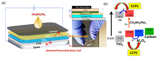
Figure 1.
The (a) schematic representation of the ambient PSC device architecture, with TiO2 as the electron transporting layers (ETL), Al2O3 as a hole transporting layer (HTL), WO3 added carbon back electrode, Li-doping facilitated electron-hole separation, and CH3NH3PbI3 injected on top of the carbon layer, with a photograph of a fabricated PSC device, and (b) an energy level diagram of the different layers of the PSC.
The use of the CPV system for BIPV application and power generation remains a trending topic for researchers. The compound parabolic concept has been utilized in a handful of studies for solar energy applications [22,23,24,25]. In this study, the concentrator system was fabricated by utilizing a concentrated optic on the top of PSC and assembling it using ultra-violet (UV) curable adhesive. The concentrated unit was placed on the PSC base with Sylgard 184 adhesive. After alignment, the concentrator unit was placed under a UV lamp at low power to cure. The alignment procedure was crucial, and precautions were needed to avoid misalignment. Afterwards, the cured concentrator unit was removed from UV lamp treatment and was ready to study. Figure 2a (top view) and Figure 2b (side view) show the CCPCs photograph and CCPC placement on PSC, expressly indicating greater optical device transparencies. Figure 2c presents the schematic representation of a CCPC optic where the incident light is concentrated via total internal reflection.
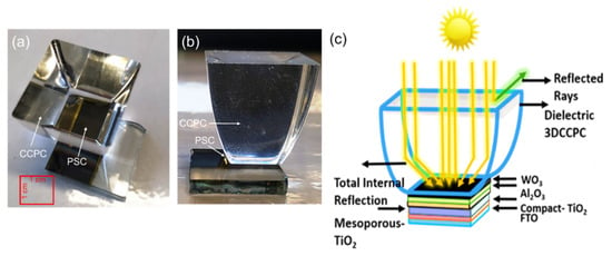
Figure 2.
A (a) top-view and (b) side-view photograph of CCPC integrated PSC, with a (c) schematic diagram of the CCPC- integrated-PSC device, employing different PSC layers and light conditioning techniques.
3. Device Characterization
CCPCs, which are made of glass with a transmissivity of over 95% for the visible range, are widely used for LCPV application. The CCPC has a concentration ratio of 2.4×, allowing the system to be static. As a result, a large part of the diffuse solar radiation is collected in the solar cell and all the direct solar radiation incident to the device’s aperture. The PSC was developed at room temperature using carbon as a counter electrode. The integrated device under testing is shown in Figure 3. This combines an AAA+ WACOM solar simulator (WACOM ELECTRIC CO., LTD., Saitama, Japan) and a continuous high-speed measuring unit, as shown in Figure 3. An EKO MP-160i I-V Tracer (EKO Instruments Europe B.V., Lulofsstraat, Netherlands) was used to record PV characteristics. The testing of the fabricated PSC device was carried out for each case.
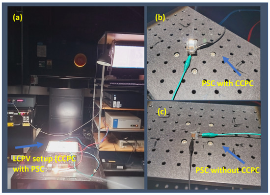
Figure 3.
(a) Photograph of the experimental characterization of the CCPC-integrated-PSC exposed under different sun conditions, starting with 1000 W/ m2, followed by 800 W/m2, 600 W/m2, and 400 W/m2 at 1.5 AM with room temperature at 22 °C; the active area of the device was 1 cm2, (b) PSC with CCPC and (c) PSC without CCPC.
The PSC device’s detailed structure, integrated with the CCPC optics, is shown in Figure 2a. Figure 2b,c show the CCPC integrated device’s photograph, which expressly indicates greater optical device transparencies. The measurements were performed for the various solar radiation intensity ranges with a room temperature of 20 °C. The optical measurements were carried out using a PerkinElmer Lambda 1050+ UV/Vis/NIR spectrophotometer (Shimadzu UK Limited, Buckinghamshire, UK) for the wavelength range of 175 nm to 3300 nm. A Bentham PVE300 Photovoltaic EQE (IPCE) (BENTHAM, Reading, UK), under 300–1100 nm, was used to measure incident photon-to-current conversion. The experimental set up under the simulator is shown in Figure 3. The variation of solar irradiance was performed, starting at 1000 W/m2 and then reduced to 800 W/m2, 600 W/m2, and 400 W/m2. The active device area was 1 cm2, and the room temperature was 22 °C throughout the experiment.
4. Results and Discussion
The devices’ optical and photovoltaic properties were measured under 1 sun 1.5 A.M., and the active area of the device was 1 cm2. Solar transmission is of greater importance for the PSC and integrated device when considering the BIPV, where daylighting is an essential evaluation criterion for overall device performance. While maintaining daylighting, both electricity generation through the PSC device and adequate overall heat loss coefficient significantly added such a device for BIPV application. Therefore, to provide a good level of daylighting where a significant part of the visible wavelength is transmitted through the device, and generate electricity from the same device, is of greater importance. As indicated earlier, the optical measurements were conducted for both the PSC device and the PSC device integrated with the CCPC optics. The glass-based CCPC optics provide an additional overall heat loss coefficient similar to those of the double-glazed window properties; hence, such optics integrated with the PSC device adequately provide both the optical transmission and the improved thermal properties of the devices. The optical characterization of both devices for different wavelength is shown in Figure 4. It was demonstrated that the external quantum efficiency (EQE) was reduced for the wavelength of above 600 nm. However, the EQE was higher compared to the CCPC integrated single-crystalline silicon-based solar cell. This indicates improved photovoltaic performance for the integrated device. Interestingly, the EQE of PSC devices showed a higher value around 350 nm and drastically reduced in the higher wavelength due to the perovskite’s degradation concerning unreacted PbI2. Moreover, the EQE of PSC CCPC resulted in a higher value than without CCPC, which corroborates the JSC values that culminated in I-V measurement.
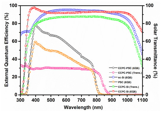
Figure 4.
The plot of the external quantum efficiency (EQE) and solar transmission variation for PSC and CCPC-integrated-PSC devices compared with single crystalline silicon solar cells consisting of a similar active area of 1 cm2.
The concentrated optic-based perovskite and concentrated optic-based silicon cell were compared. The maximum solar transmission of 30% was achieved for a wide range of wavelengths, between 300 nm to 800 nm, which was relatively higher than the silicon-based solar cell. The absorbance measurement was also carried out with the same conditions. Surprisingly, the perovskite-based solar cell showed lower absorbance and more transparency across the near-infrared region of the silicon-based solar cell, as shown in Figure 5. The PSC exhibited near infra-red absorption originating from the carbon back contact, allowing more light absorption to the perovskite. The absorption measurement was taken to understand a complete PSC’s absorption behaviour (with back contact) with a single crystalline silicon cell. This result also signifies that the semi-transparent PSC has future applications for BIPV integration.
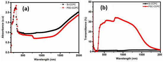
Figure 5.
The plot of (a) absorbance and (b) transmittance spectra of CCPC-integrated-PSC compared with CCPC integrated single crystalline silicon cell, consisting of a similar active area of 1 cm2.
It was found that maximum efficiency of 89% was achieved as compared to the solar cell without the CCPC optical device. Table 1 presents the device’s photovoltaic performance for a wide range of conditions for both the PSC and PSC integrated CCPC devices. Maximum efficiency of 9.10% was reported, which shows a significant increase of 16.36% compared to the device without optical integration. The related current density-voltage and the power curves for both devices are shown in Figure 6 for solar radiation intensities of 400 Wm−2, 600 Wm−2, 800 Wm−2 and 1000 Wm−2.

Table 1.
Photovoltaic performance of carbon-based perovskite solar cells, with and without CCPC, over an active area of 1 cm2.
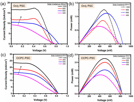
Figure 6.
A plot of photovoltaic parameters variation such as (a,c) current-density vs circuit voltage (forward scan), and (b,d) power vs open-circuit voltage under different solar irradiance for the PSC and CCPC-integrated-PSC devices.
The PSC integrated system’s performance at certain constant solar irradiance was tested to analyse different photovoltaic properties as shown in Figure 7a–d. The short circuit current (JSC) was higher for concentrated PSC than that of the regular PSC as shown in Figure 7a. In contrast, open-circuit voltage (VOC) led to almost the same values for both conditions, as shown in Figure 7b. This is because there is a marginal difference in the bandgap of the PSC materials with light intensity during a significant influence in its current density generation. The fill factor (FF) was higher for regular PSC than a lowered PCE (%). The deterioration of FF attributes exceeds solar irradiance (Figure 7c). The FF decrease originates from either contact resistance between internal layers, and parasitic resistance exerted from in the fluorine-doped tin oxide (FTO) or resistance in the charge extraction layer of the device. The FF and power density varied proportionally with the solar irradiance. However, for concentrated BIPV applications, the development of the contact layer, device architecture, and PSC stability against degradation when exposed to solar irradiance was reported to be helpful [26]. For concentrated PSC, PCE (%) was higher than regular PSC due to the high absorbance property of perovskite and the concentrator optic (Figure 7d). The power against solar irradiance showed a higher value for concentrated PSC than for regular PSC. Interfacial traps between m-TiO2 and the perovskite heterojunction can sometimes cause a trade-off between PCE and the power output of PSCs.
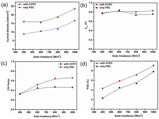
Figure 7.
Plots of various photovoltaic parameters such as (a) current density, (b) open-circuit voltage, (c) fill factor, and (d) power conversion efficiency of the PCE compared with CCPC integrated PSC.
There was a noticeable improvement recorded during CCPC integration with PCE, and the PCE enhancement trend followed 1000 < 600 ~ 800 < 400 W/m2 solar irradiances, as shown in Figure 8a. Interestingly, there was a similar PCE enhancement observed for 800 and 600 W/m2. This is perhaps because of the JSC and FF trade-off, as the VOC remained almost identical for these conditions. Usually, the greater the light intensity, the better the PCE of the solar cell. However, it was observed that the CCPC-integrated-PSC functioned well under low solar irradiance, where a maximum PCE enhancement was observed at ~90%. The low temperature, low-intensity condition may restrict the degradation of the perovskite, resulting in higher efficiency enhancement. The thickness of the devices is also essential; as the sun was elevated due to the thickness, a charge extraction loss may happen [27,28,29,30]. The PCE result indicates that CCPC integration contributes to an improvement of weak light performance.
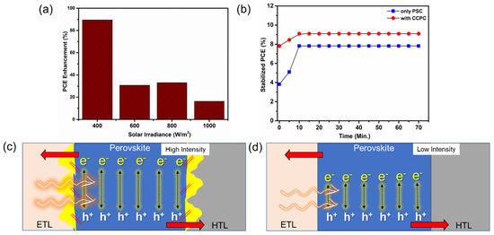
Figure 8.
The (a) plot of power conversion efficiency (PCE) enhancement for different solar irradiance, (b) PCE stabilization kinetics plot for CCPC-integrated-PSC compared with PSC, and the schematic representation of photo-generated charge carries for (c) high-intensity and (d) low-intensity concentrated light, respectively, where the yellow markings indicate degradation of the perovskite, the arrow’s intensity indicates high and low incidence irradiance, and the red arrows represent the charge-carrier migration direction.
The light soaking test of regular perovskite and concentrated optic under 1 sun A.M. was carried out. However, the involvement of sunlight with a UV element accelerated the degradation pattern. Both stable perovskite and concentrated optic stayed stable for ~70 min. However, the PCE (%) was higher for the concentrated system than the regular perovskite. Stable perovskite showed an initial PCE of 4% and reached 8%, while concentrated optic-based perovskite showed an initial efficiency of 8% to 9.5%, as shown in Figure 8b.
The degradation phenomena were assisted by electron injection into titanium oxide trapped by the unoccupied sides [31]. When exposed to high incident light or low open-circuit conditions, mesoporous-layer-based perovskites are confirmed to have the property of degradation. Degradation phenomena were also ascribed to the catalytic role of metal oxide and instability issues when exposed to sunlight.
It is anticipated that, during higher irradiance, the photo-generate charge carriers of perovskite have rapid mobility across the cell compared to lower irradiance. However, the perovskite layer suffered from degradation due to the high-temperature generation of concentrated light, losing its expected PCE outcome. Whereas, for lower light irradiance, the perovskite’s degradation may be restricted. However, due to less sunlight, the charge-carrier migration became steady. Therefore, this photo-physical deportment’s synergistic effect resulted in PV performance variation of CCPC-integrated-PSC at different solar irradiance. Figure 8c,d further illustrate the above-mentioned photo-physical behaviour’s synergistic effect for the concentrated light schematically.
However, the extra heating by concentrated solar irradiance and the subsequent elevation of cell temperature, and its effect on the cell performance and stability, was also a matter of investigation. In our case, we found for our PSC structure that solar irradiance of 400 w/m2 exhibited maximum efficiency enhancement (90%), which is quite reliable, and did not increase the device temperature via illumination. However, constant illumination for higher concentrated suns caused temperature to increase, resulting in perovskite degradation. This can only be prevented by applying an encapsulation layer or employing Pb-free perovskite [32,33]. Implementing the interfacial layers to enhance the charge-carrier lifetime (>10 µs) provided a stable PSC for high solar irradiance tolerance [31]. Similarly, from the optics side, incorporating UV-stabilised material to construct solar concentrators that restrict the UV part of the solar spectrum can reduce the device’s degradation. Most of the layer components strongly absorb the UV portion of incidence sunlight [34]. Allowing for an additional layer or new material will further affect the optic’s transparency. However, the device’s stability can be achieved. Therefore, there is an intriguing challenge between stability and transparency when we consider concentrated PSC devices.
Inevitably, the cell performance limitations are now linked with other parameters such as limiting device lifetime, poor moisture stability of the perovskite, and the toxicity of Pb, which could preclude some application areas for the devices [35,36]. While struggling to invest time on the issues mentioned earlier, optics integration commits an excellent value for efficiency enhancement of the PSC. In this study, an attempt was made to understand the effect of concentrated light on the PV parameters. The initial results are encouraging, with further incorporation of the CPV into the building architecture envisaged. However, the extra heating by the concentrated solar irradiance and subsequent elevation of cell temperature and its effect on the cell performance and stability is also a matter for investigation. Nevertheless, there is enough room for PSC development for deployment in CPV units soon.
5. Conclusions
This work introduces a new set of perovskite solar cell (PSC) devices with CCPC optics for increased efficiency and substantial stability under different solar irradiance. Optical and electrical performances of PSC have been executed with and without CCPC under different sun intensity. We found that the device’s short circuit current density tended to increase linearly with solar irradiance. The open-circuit voltage of the device coupled with CCPC also increased fractionally with increasing solar intensity level.
CCPC inclusion under 400 W/cm2 boosted the efficiency to ~90%, whereas, under 1000 W/cm2, efficiency enhancement was found to be ~16% compared to PSCs without CCPC. This result further generates a deep interest in indoor photovoltaics. The observed efficiency was retained long-term for up to 70 min for both systems. However, substantial deterioration in fill factor was observed, which affected the PCE of the device.
We conclude that device and material stability under increased solar irradiance needs to be considered to implement perovskite with concentrated optics. Furthermore, there is clear room for improvement by controlling layer deposition steps. Some gaps need to be addressed concerning CCPC integration issues, including PSC active area and PSC device dead area. The results put forward the idea of CPV integration with PSC as an effective way to improve PV device efficiency. Fabrication of CCPC optics is low-cost, straightforward, and economically feasible for the commercial market.
Furthermore, CPV emplacement reduces PV materials cost and fabrication complexation by redirecting the incident light towards the smaller PV. In this way, we can minimise fabrication and material cost for the PSCs and further shrink the economic cost of installing large-area PSCs. Because of their high efficiency in a much shorter time, PSC technology will be an effective means for energy production in the coming years if the stability issue can be resolved.
Author Contributions
T.K.M. and S.S. conceived of the presented idea and planned the experiments. S.B. and A.R. fabricated the perovskite solar cells. Professor T.K.M. encouraged M.K. to investigate the PSC system by integrating a cross-compound parabolic optic unit and supervised the findings of this work. M.K. carried out the optical part of the experiments. A.R. was involved in planning experimental work and supervised the work. All authors provided critical feedback and helped shape the research, analysis, and manuscript. All authors have read and agreed to the published version of the manuscript.
Funding
The funding from Engineering and Physical Science Research Council through EUED Tech 2019 project (EP/S030786/1) is acknowledged.
Institutional Review Board Statement
Ethical review and approval are not applicable for this study due to the reasons that the studies do not involving humans or animals.
Conflicts of Interest
The authors declare no conflict of interest.
References
- Yang, W.S.; Noh, J.H.; Jeon, N.J.; Kim, Y.C.; Ryu, S.; Seo, J.; Seok, S.I. High-performance photovoltaic perovskite layers fabricated through intramolecular exchange. Science 2015, 348, 1234–1237. [Google Scholar] [CrossRef] [PubMed]
- Xing, G.; Mathews, N.; Lim, S.S.; Lam, Y.M.; Mhaisalkar, S.; Sum, T.C. Long-Range Balanced Electron- and Hole-Transport Lengths in Organic-Inorganic CH3NH3PbI3. Science 2013, 6960, 498–500. [Google Scholar] [CrossRef]
- Seo, J.; Noh, J.H.; Seok, S.I. Rational Strategies for Efficient Perovskite Solar Cells. Acc. Chem. Res. 2016, 49, 562–572. [Google Scholar] [CrossRef]
- Eperon, G.E.; Stranks, S.D.; Menelaou, C.; Johnston, M.B.; Herz, L.M.; Snaith, H.J. Formamidinium lead trihalide: A broadly tunable perovskite for efficient planar heterojunction solar cells. Energy Environ. Sci. 2014, 7, 982–988. [Google Scholar] [CrossRef]
- Noh, J.H.; Im, S.H.; Heo, J.H.; Mandal, T.N.; Seok, S.I. Chemical management for colorful, efficient, and stable inorganic-organic hybrid nanostructured solar cells. Nano Lett. 2013, 13, 1764–1769. [Google Scholar] [CrossRef]
- Wang, J.T.W.; Ball, J.M.; Barea, E.M.; Abate, A.; Alexander-Webber, J.A.; Huang, J.; Saliba, M.; Mora-Sero, I.; Bisquert, J.; Snaith, H.J.; et al. Low-temperature processed electron collection layers of graphene/TiO2 nanocomposites in thin film perovskite solar cells. Nano Lett. 2014, 14, 724–730. [Google Scholar] [CrossRef] [PubMed]
- Green, M.A.; Ho-Baillie, A.; Snaith, H.J. The emergence of perovskite solar cells. Nat. Photonics 2014, 8, 506–514. [Google Scholar] [CrossRef]
- Snaith, H.J. Perovskites: The emergence of a new era for low-cost, high-efficiency solar cells. J. Phys. Chem. Lett. 2013, 4, 3623–3630. [Google Scholar] [CrossRef]
- Bhandari, S.; Roy, A.; Ghosh, A.; Mallick, T.K.; Sundaram, S. Perceiving the temperature coefficients of carbon-based perovskite solar cells. Sustain. Energy Fuels 2020, 4, 6283–6298. [Google Scholar] [CrossRef]
- Li, F.; Liu, M. Recent efficient strategies for improving the moisture stability of perovskite solar cells. J. Mater. Chem. A 2017, 5, 15447–15459. [Google Scholar] [CrossRef]
- Tsutomu, M.; Akihiro, K.; Kenjiro, T.; Yasuo, S. Organometal halide perovskites as visible-light sensitizers for photovoltaic cells. J. Am. Chem. Soc. 2009, 131, 6050–6051. [Google Scholar] [CrossRef]
- Leo, K. Signs of stability. Nat. Nanotechnol. 2015, 10, 574–575. [Google Scholar] [CrossRef]
- Zhao, X.G.; Yang, D.; Ren, J.C.; Sun, Y.; Xiao, Z.; Zhang, L. Rational Design of Halide Double Perovskites for Optoelectronic Applications. Joule 2018, 2, 1662–1673. [Google Scholar] [CrossRef]
- Wang, Z.; Lin, Q.; Wenger, B.; Christoforo, M.G.; Lin, Y.H.; Klug, M.T.; Johnston, M.B.; Herz, L.M.; Snaith, H.J. High irradiance performance of metal halide perovskites for concentrator photovoltaics. Nat. Energy 2018, 3, 855–861. [Google Scholar] [CrossRef]
- Available online: https://www.nrel.gov/pv/assets/pdfs/best-research-cell-efficiencies.20200708.pdf (accessed on 24 January 2021).
- Baig, H.; Kanda, H.; Asiri, A.M.; Nazeeruddin, M.K.; Mallick, T. Increasing efficiency of perovskite solar cells using low concentrating photovoltaic systems. Sustain. Energy Fuels 2020, 4, 528–537. [Google Scholar] [CrossRef]
- Misra, R.K.; Aharon, S.; Li, B.; Mogilyansky, D.; Visoly-Fisher, I.; Etgar, L.; Katz, E.A. Temperature- and component-dependent degradation of perovskite photovoltaic materials under concentrated sunlight. J. Phys. Chem. Lett. 2015, 6, 326–330. [Google Scholar] [CrossRef] [PubMed]
- Almansouri, I.; Green, M.A.; Ho-Baillie, A. The ultimate efficiency of organolead halide perovskite solar cells limited by Auger processes. J. Mater. Res. 2016, 31, 2197–2203. [Google Scholar] [CrossRef]
- Bhandari, S.; Roy, A.; Ghosh, A.; Mallick, T.K.; Sundaram, S. Performance of WO3-Incorporated Carbon Electrodes for Ambient Mesoscopic Perovskite Solar Cells. ACS Omega 2020, 5, 422–429. [Google Scholar] [CrossRef]
- Baig, H.; Sellami, N.; Chemisana, D.; Rosell, J.; Mallick, T.K. Performance analysis of a dielectric based 3D building integrated concentrating photovoltaic system. Sol. Energy 2014, 103, 525–540. [Google Scholar] [CrossRef]
- Green, M.; Emery, K.; Hishikawa, Y.; Warta, W.; Dunlop, E. Solar cell efficiency tables (version 40). IEEE Trans. Fuzzy Syst. 2012, 20, 1114–1129. [Google Scholar] [CrossRef]
- Mammo, E.D.; Sellami, N.; Mallick, T. Performance analysis of a reflective 3D crossedcompound parabolic concentrating photovoltaic system for building façade integration. Prog. Photovolt. Res. Appl. 2013, 21, 1095–1103. [Google Scholar] [CrossRef]
- Al-Shidhani, M.; Al-Najideen, M.; Rocha, V.G.; Min, G. Design and testing of 3D printed cross compound parabolic concentrators for LCPV system. AIP Conf. Proc. 2018, 2012. [Google Scholar] [CrossRef]
- Shanks, K.; Knowles, A.; Brierly, A.; Baig, H.; Sun, Y.; Wu, Y.; Mallick, Y. Prototype optical modelling procedure and outdoor characterization of an embedded polyolefin crossed compound parabolic concentrator for integrated photovoltaic windows. AIP Conf. Proc. 2019, 2149, 030005-1–030005-6. [Google Scholar] [CrossRef]
- Han, Q.; Hsieh, Y.T.; Meng, L.; Wu, J.L.; Sun, P.; Yao, E.P.; Chang, S.Y.; Bae, S.H.; Kato, T.; Bermudez, V.; et al. High-performance perovskite/ Cu(In,Ga)Se2 monolithic tandem solar cells. Science 2018, 361, 904–908. [Google Scholar] [CrossRef]
- Ryu, S.; Nguyen, D.C.; Ha, N.Y.; Park, H.J.; Ahn, Y.H.; Park, J.Y.; Lee, S. Light Intensity-dependent Variation in Defect Contributions to Charge Transport and Recombination in a Planar MAPbI3 Perovskite Solar Cell. Sci. Rep. 2019, 9, 1–12. [Google Scholar] [CrossRef]
- Du, T.; Xu, W.; Xu, S.; Ratnasingham, S.R.; Lin, C.T.; Kim, J.; Briscoe, J.; McLachlan, M.A.; Durrant, J.R. Light-intensity and thickness dependent efficiency of planar perovskite solar cells: Charge recombinationversusextraction. J. Mater. Chem. C 2020, 8, 12648–12655. [Google Scholar] [CrossRef]
- Zhu, S.; Li, Y. Performances of perovskite solar cells at low-intensity light irradiation. Solid State Electron. 2020, 173, 107903. [Google Scholar] [CrossRef]
- Leijtens, T.; Eperon, G.E.; Pathak, S.; Abate, A.; Lee, M.M.; Snaith, H.J. Overcoming ultraviolet light instability of sensitized TiO2 with meso-superstructured organometal tri-halide perovskite solar cells. Nat. Commun. 2013, 4, 1–8. [Google Scholar] [CrossRef] [PubMed]
- Corsini, F.; Griffini, G. Recent progress in encapsulation strategies to enhance the stability of organometal halide perovskite solar cells. J. Phys. Energy 2020, 2, 031002. [Google Scholar] [CrossRef]
- Fu, H. Review of lead-free halide perovskites as light-absorbers for photovoltaic applications: From materials to solar cells. Sol. Energy Mater. Sol. Cells 2019, 193, 107–132. [Google Scholar] [CrossRef]
- Troughton, J.; Gasparini, N.; Baran, D. Cs0.15FA0.85PbI3 perovskite solar cells for concentrator photovoltaic applications. J. Mater. Chem. A 2018, 6, 21913–21917. [Google Scholar] [CrossRef]
- Aklalouch, M.; Calleja, A.; Granados, X.; Ricart, S.; Boffa, V.; Ricci, F.; Puig, T.; Obradors, X. Hybrid sol-gel layers containing CeO2 nanoparticles as UV-protection of plastic lenses for concentrated photovoltaics. Sol. Energy Mater. Sol. Cells 2014, 120, 175–182. [Google Scholar] [CrossRef]
- Mora-Seró, I.; Saliba, M.; Zhou, Y. Towards the Next Decade for Perovskite Solar Cells. Sol. RRL 2020, 4, 3–4. [Google Scholar] [CrossRef]
- Li, N.; Niu, X.; Chen, Q.; Zhou, H. Towards commercialization: The operational stability of perovskite solar cells. Chem. Soc. Rev. 2020, 49, 8235–8286. [Google Scholar] [CrossRef] [PubMed]
- Su, P.; Liu, Y.; Zhang, J.; Chen, C.; Yang, B.; Zhang, C.; Zhao, X. Pb-based perovskite solar cells and the underlying pollution behind clean energy: Dynamic leaching of toxic substances from discarded perovskite solar cells. J. Phys. Chem. Lett. 2020, 11, 8. [Google Scholar] [CrossRef]
Publisher’s Note: MDPI stays neutral with regard to jurisdictional claims in published maps and institutional affiliations. |
© 2021 by the authors. Licensee MDPI, Basel, Switzerland. This article is an open access article distributed under the terms and conditions of the Creative Commons Attribution (CC BY) license (https://creativecommons.org/licenses/by/4.0/).