Article

Developing a Cold Accumulator with a Capsule Bed Containing Water as a Phase-Change Material

Faculty of Infrastructure and Environment, Czestochowa University of Technology, 60A Brzeznicka St., 42-201 Czestochowa, Poland
*
Author to whom correspondence should be addressed.
Energies 2021, 14(9), 2703; https://doi.org/10.3390/en14092703
Submission received: 6 April 2021 / Revised: 30 April 2021 / Accepted: 6 May 2021 / Published: 8 May 2021

Abstract

:
The paper presents the investigation of a prototype cold accumulator using water–ice latent heat for the cold storage process. The concept of the cold accumulator was based on a 200-L-capacity cylindrical storage tank in which spherical capsules filled with water were placed. Beds of polypropylene capsules with diameters of 80 mm, 70 mm, and 60 mm were used in the tests. The cold accumulator operated with a water–air heat pump. Based on the test results, the following parameters were calculated: the cooling capacity, cooling power, energy efficiency of the cold storage, and energy efficiency ratio (EER) of the accumulator. The obtained measurement results were described with mathematical relationships (allowing for measurement error) using criterial numbers and the developed “Research Stand Factor Number” (RSFN) index. It has been found that, for the prototype cold accumulator under investigation, the maximum values of the cooling capacity (17 kWh or 85.3 kWh per cubic meter of the accumulator), energy efficiency (0.99), and EER (4.8) occur for an RSFN of 144 · 10 4 . The optimal conditions for the operation of the prototype cold accumulator were the closest to laboratory tests conducted for a bed with capsules with a diameter of 70 mm and a mass flow of the water–glycol mixture flowing between the accumulator and the heat pump of 0.084 kg/s. During the tests, no significant problems with the operation of the prototype cold accumulator were found.

Graphical Abstract

1. Introduction

In the majority of European countries, the demand for cooling in residential and public buildings is unpredictable. The maximum demand for cooling power occurs rarely and then only for short periods of time. At the same time, this demand directly influences the nominal cooling power when selecting devices for a cooling installation in a building [1]. One of the directions for improving the energy performance of this type of installation is to use cold storage with a simultaneous reduction of the nominal cooling power of the cold source [2,3,4]. This solution enables the storing of cold air when the cold demand is lower than the nominal power of the cooling devices and then using it at times when peak loads exceeding the cooling device’s power occur [5]. The effective use of cold storage requires, however, a high energy storage density or high energy efficiency [6,7,8]. However, it allows for significant energy and economic effects [1,9,10,11]. The implementation of energy storage systems for the reduction of energy consumption in the building sector is currently one of the most challenging research topics [12,13,14,15,16]. The most common solution currently used in cold storage processes in the technical systems of buildings is ice water. In such a solution, cold is accumulated by using the thermal capacity of water. However, this process is characterized by a low storage density. This creates the need for cold tanks of a considerable volume [17,18]. To overcome this problem, cold tanks producing ice on coil heat exchangers started to be employed [19]. This enables the utilization of the heat of water–ice phase change for cold storage. Devices with either external or internal ice melting can be distinguished here. Using tanks of this type creates, however, a number of new problems not occurring in ice water tanks. One of the most significant issues is the need for compensation for the negative effect of the thermal expansion of ice during water freezing. As a result of the change in its internal structure, ice increases in volume by approx. 10% compared to water of the same mass. In addition, the cold tanks producing ice on coil heat exchangers must use a minimum of two circulations to enable its regeneration, which often complicates the technical installation [20]. It should be emphasized here that tanks of this type are most commonly used in heating systems as a lower source of energy for the heat pump [21,22]. A drawback of such reservoirs is the inability to utilize the whole volume of water in the tank— usually, the working volume of these tanks is 80% of the total tank volume. The thermal expansion problem was eliminated by employing tanks using binary ice or a suspension of fine ice particles in a water solution. The advantage of this solution is commonly considered to be the possibility of forcing binary ice through the installation’s lines as a homogeneous liquid [23]. Binary ice, however, has its disadvantages. The first of them is the need for using ice generators totally separate from the cold source of a building’s cooling system. An added difficulty of using binary ice is the necessity of adding substances that lower the water freezing point to the water to allow the liquid to be overcooled and maintain ice in a solid phase. This makes the number of binary ice working cycles dependent on the delamination of the mixture. Melting the ice directly in the mixture makes the regeneration of the bed difficult because of the primary mixture losing its physical characteristics due to dilution with water [24]. A solution to this problem may be the use of water-filled capsules as a bed in the cold tank [25,26,27]. Such capsules can form a direct packing of tanks. The capsules may occur as either micro- or macrocapsules [28]. Microcapsules are particles of phase-change material (PCM) of a size of up to 1000 μm, closed within thin and, at the same time, strong casings. Such capsules are used as an element of constructional or insulating materials or placed in a special matrix enabling the capsules to be used in a cold tank [29,30]. Macrocapsules, i.e., capsules of sizes not larger than 1000 μm, may have the form of tubes, pouches, spheres, panels, or other containers or ampoules [28,31,32,33,34]. Regardless of the cold storage solution adopted, ice is attractive due to its wide availability and low cost compared to other PCM materials. In addition, ice is neutral for the natural environment and human health. This is an important aspect to consider in terms of the installation, operation, and possible failures of a cold tank. Using additive-free pure ice closed in capsules eliminates the problem of ice pressure on the tank walls during freezing and does not limit the number of possible cold tank operation cycles. As the capsule is filled with water for 90% of its volume, the incrementing ice will result in filling it almost to 100%. In addition, the capsule has some tolerance to stretching caused by the ice increment. Experiments with HDPE (High-density polyethylene) capsules [35] have shown that the spherical capsule may increase in volume by 7% without losing the tightness and then revert to the original condition after the ice has melted. So, the phenomenon of the thermal expansion of water as it freezes does not affect the tank’s construction. Another important issue is the management of waste heat generated during the charging of the cold accumulator [6]. Based on the review of the current state of knowledge, it has been assumed that using encapsulated ice as cold tank packing eliminates the effects of thermal expansion typical of exchangers producing ice on the coil. Encapsulated ice allows an unlimited number of cold tank operation cycles. Because of the complete isolation of the ice from the working fluid in the cooling system, there is no possibility of losing the physicochemical properties of the fluid due to its dilution with water. Thanks to the isolation of the ice from the working fluid, it is possible to use a single storage installation both for charging and discharging of the cold tank. By utilizing the heat of the water–ice phase change, it is possible to achieve a high cold storage density [24,26].

2. Materials and Methods

2.1. The Object of Investigation

In the framework of the study, a testing stand was constructed to determine the characteristic states of operation of the prototype cold accumulator. The proposed cold accumulator utilizes the heat of the water–ice phase change for the process of cold storage. The concept of the cold accumulator was based on a 200-L-capacity cylindrical storage tank (with a height of 0.78 m and a diameter of 0.57 m) in which spherical capsules filled with water were placed. The adopted size of the tank made it possible, on the one hand, to carry out tests on a commercial scale (1:1 scale) and, on the other hand, to use the laboratory testing infrastructure to correctly control the thermal and flow conditions during measurements. Beds made up of polypropylene capsules (HDPP) in three different diameters, namely 400 capsules of a diameter of 80 mm, 542 capsules of a diameter of 70 mm, and 959 capsules of a diameter of 60 mm, were used in the tests. The polypropylene capsule, compared to, for example, the polyethylene capsule (HDPE), has higher chemical resistance, better withstands low temperatures, and does not undergo corrosion due to the penetration of moisture into the material and its freezing inside it. Compared to HDPE, HDPP is stiffer and harder at the same wall thickness. The choice of capsule diameters did not result from advanced numerical analyses. The adopted criteria are, on the one hand, the minimization of capsule purchasing costs (as well as water encapsulation costs), the reduction of the excessive resistance of flow through the bed in the case of an excessive number of fine capsules, and the maximization of the water capacity of capsules. The reference value that was adopted is the expected bed porosity in the range from 0.45 to 0.55. Similar capsule diameters of 40 mm, 50 mm, and 70 mm were also adopted in the research [36]. The capsules were filled with water and flushed by the heat transfer fluid (HTF) in the cold storage installation, i.e., a water–glycol mixture with a 33% fraction of propylene glycol. The characteristic parameters of the water–glycol mixture are given in Table 1.
Capsules with diameters of 60 and 70 mm, respectively, were made colorless for the better control of the degree of water fill-up of the capsules and checking their tightness at the time of tank opening for control purposes. For technological reasons, 80-mm-diameter capsules were made white by adding a powdered dye. The purpose of this was to increase the rigidity of the capsule wall. The capsules were filled with water up to a volume of 90%. The remaining 10% of the free space got filled with ice due to the change in the volume of water as it froze. The free space assumed when filling the capsules protected the capsule against possible unsealing. The capsules were filled with water by piercing the surface, injecting water, and then sealing the hole with a special acrylic gel with high chemical resistance and hardening in contact with air. The capsules were subjected to thermal expansion testing. To this end, a capsule was filled with water to 100% of its volume and then subjected to 20 cycles of freezing. In spite of an approximately 5% increase in the capsule volume during freezing, no unsealing was noted, either by the capsule coating cracking at the joining location or due to a loss of the properties of the adhesive used for closing up the hole after injecting the water. After thawing, the capsule reverted to its original volume without losing its tightness or mechanical properties. A view of the capsule bed being partially flooded with the water–glycol mixture is shown in Figure 1.
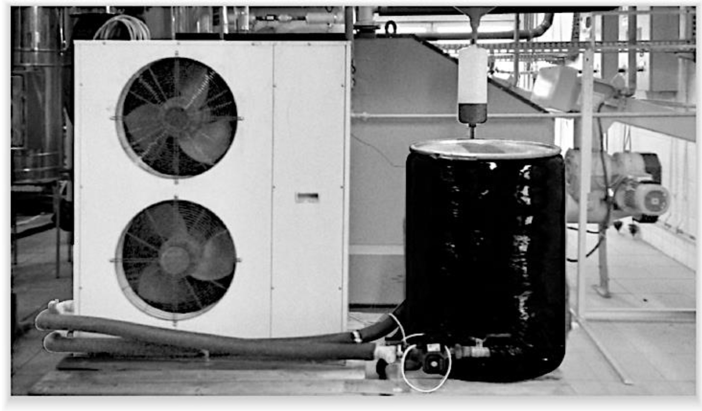
The prototype cold accumulator was operated with a modified water–air heat pump. The modification consisted of the adaptation of a heat pump designed for operation with a heat transfer fluid in the installation by replacing the heat pump’s controller. This allowed the heat pump to operate with the HTF at temperatures below 0 °C. A view of the testing stand is shown in Figure 2. Figure 3 shows a schematic diagram of the test cold storage installation coupled with the prototype cold accumulator. The testing stand was composed of: 1—air–water heat pump, 2—installation venting line with a ball valve, 3—circulation pump on the supply line, 4—prototype cold accumulator with phase-change material in the bed system with capsule packing material, 5—expansion vessel, and 6—heat removal from the heat pump.
The testing stand was provided with the following measurement points: T—temperature sensors (thermocouples) on the supply line, on the return line, and in the accumulator, Tc—the control temperature sensor of the heat pump controller, FM—an electromagnetic flowmeter, RDS—a measurement data recording system, SP-EM—an electricity meter (single-phase), and TP-EM—an electricity meter (three-phase). The thermocouples measuring the cold accumulator temperature were placed inside the capsules. The purpose of placing thermocouples inside the capsules was to more accurately determine the points for starting the phase change in the capsules. For the purposes of the study, electricity meters for the three-phase electric power system supplying the heat pump and the single-phase electric power system supplying the measurement data recording system were also used. In addition, downstream of the outlet of the working fluid from the cold accumulator, a temperature sensor T6 was installed. This sensor was wired directly to the heat pump controller and provided protection against HTF overcooling below the temperature preset on the controller. The initial accumulator temperature was equal to the ambient temperature, while the minimum cooling temperature attainable by the heat pump was −25 °C. This is a technical limitation that results from the operational capability of the heat pump’s compressor unit.
In a measurement series, no undesirable reactions between the capsule coating with the cyanoacrylate gel and the circulating fluid were found. By contrast, the water–glycol mixture was found to have negatively affected the installation connections sealed with Teflon tape and colorless sanitary silicone. After prolonged exposure, graying of the tape along with its slow dissolving was noted, as well as dyeing of the silicon light blue by the coloring agent from the glycol used in the mixture as the circulating working fluid.

2.2. Testing Methodology

Nine measuring tests were carried out within the study, which differed in terms of the size of the cold accumulator bed capsules and the mass flow rate of the heat transfer fluid in the installation. A description of the tests is given in Table 2.
The duration of the test was defined as the time within which the heat transfer fluid temperature at the accumulator outlet (T5) would attain a level of 0 °C. Based on the test results obtained, the following parameters were calculated: cooling capacity, cooling power, energy efficiency of cold storage, and energy efficiency ratio (EER) of the accumulator. The cooling capacity of the accumulator was assumed to be the amount of heat collected from the accumulator, tested during its charging and calculated following this relationship:
Q c s = τ i n i t τ f i n m ˙ h t f c p , h t f [ t i n ( τ ) t o u t ( τ ) ] 3600 1 d τ .
For a given time interval, the quotient of cooling capacity to measuring duration was used for calculating the instantaneous cooling power of the cold accumulator according to the following relationship:
Q ˙ c s , i v = Q c s , i v τ i v .
The energy efficiency of cold storage was defined as the quotient of the amount of heat collected from the accumulator (Equation (1)) during a measurement series to the thermal capacity of the accumulator, as per the formula below:
η c s = Q c s H C T ,
where:
H C T = [ m w c p , w ( t i n i t t p c ) + m w L w i + m i c p , i · ( t p c t f i n ) + m h t f c p , h t f · ( t i n i t t f i n ) ] · 3600 1 .
The idea behind the definition of energy efficiency was the determination of the efficiency of using the theoretical thermal capacity of the prototype for cold storage purposes. The aim of this approach was to acquire knowledge about the usefulness of the proposed capsule beds during accumulator charging. The energy efficiency ratio was calculated as the quotient of the amount of heat collected from the accumulator to the amount of electric energy used for this purpose by all elements of the testing stand, following this relationship:
E E R = Q c s P e l .
Table 3 shows the basic operational parameters of the testing stand and cold storage installation, while the methodology for their calculation is represented by Equations (6)–(10):
ε = 1 V p N p V A
U s f , h t f = m ˙ h t f A ρ h t f
U ϕ , h t f = R e ϕ ν d p
R e ϕ = R e p { 1 ε e x p [ 5 ( 1 ε ) 3 ε ] }
R e p = U s f , h t f · d p ν .
Equation (9) is proposed on the basis of research [37].
As a result of the assumed dimensions of the accumulator and its packing, the voidage of the bed formed was the highest for 70-mm-diameter balls at 0.51. For the other two variants, the bed voidage was 0.46. The highest bed porosity for 70-mm capsules resulted from the possibility of packing them in the assumed tank geometry, i.e., the physical relationship between the capsule size and the tank’s geometry. A capsule size of 70 mm did not permit the capsules to be tightly packed in the tank. The highest velocities of heat transfer fluid flow through the bed, calculated while allowing for the voidage of the accumulator bed, occurred in tests with 70-mm-diameter capsules; these ranged from 1.25 to 1.55 m/s. The lowest flow velocities, from 0.75 to 0.94 m/s, were found for 60-mm-diameter capsules. For 80-mm-diameter capsules, the HTF amounted to 0.89 to 1.04 m/s. The measuring instrumentation used in the test installation enabled the measurements to have an accuracy of 0.5 °C for temperature (thermocouple measurement range from −50 °C to 110 °C), 2% for the mass flow rate of the heat transfer fluid (flowmeter measurement range from 0.0088 kg s−1 to 0.2896 kg s−1) and 0.1 kWh for electric energy consumption.

3. Results and Discussion

3.1. Measurement Results

3.1.1. Operation of the Testing Stand

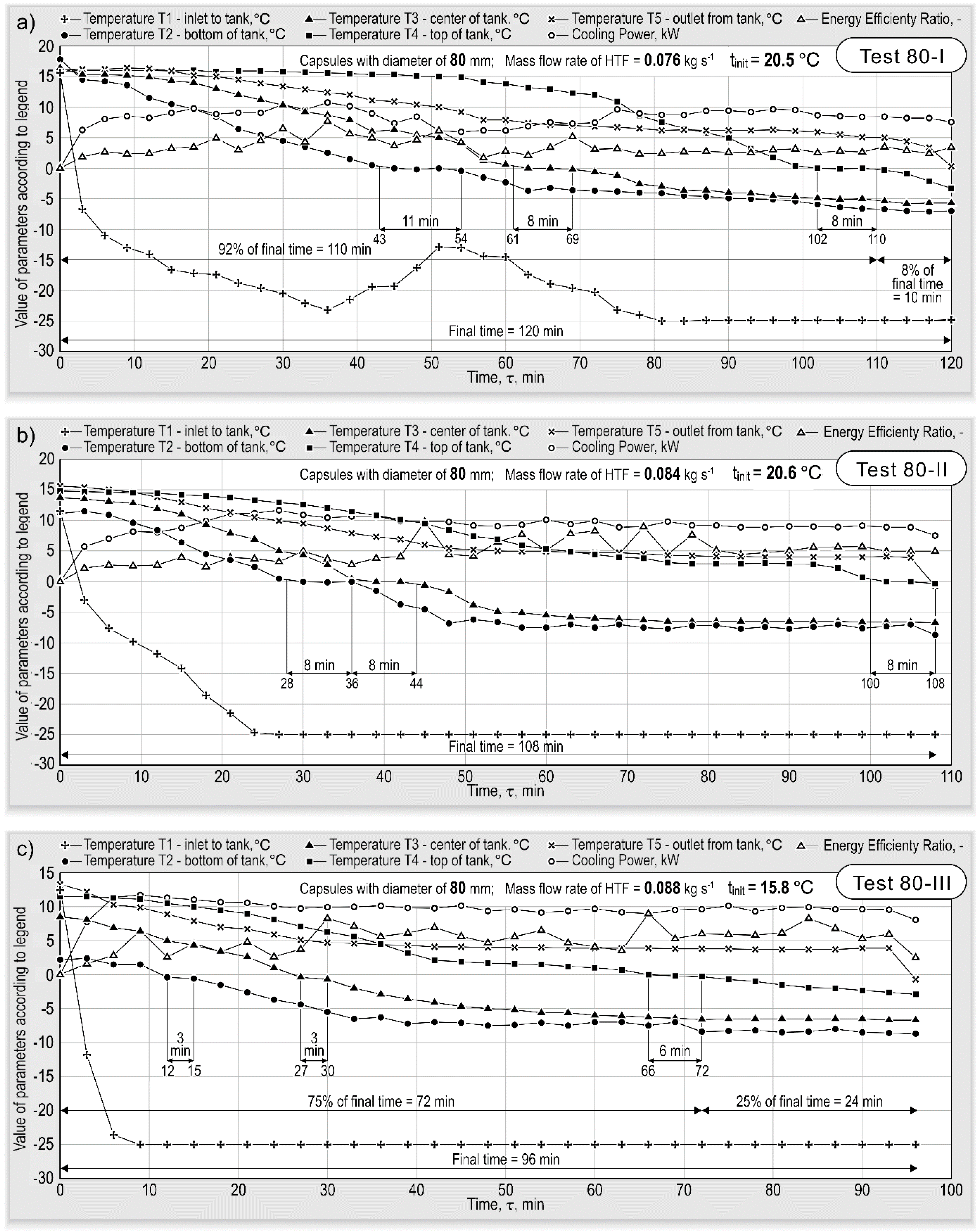
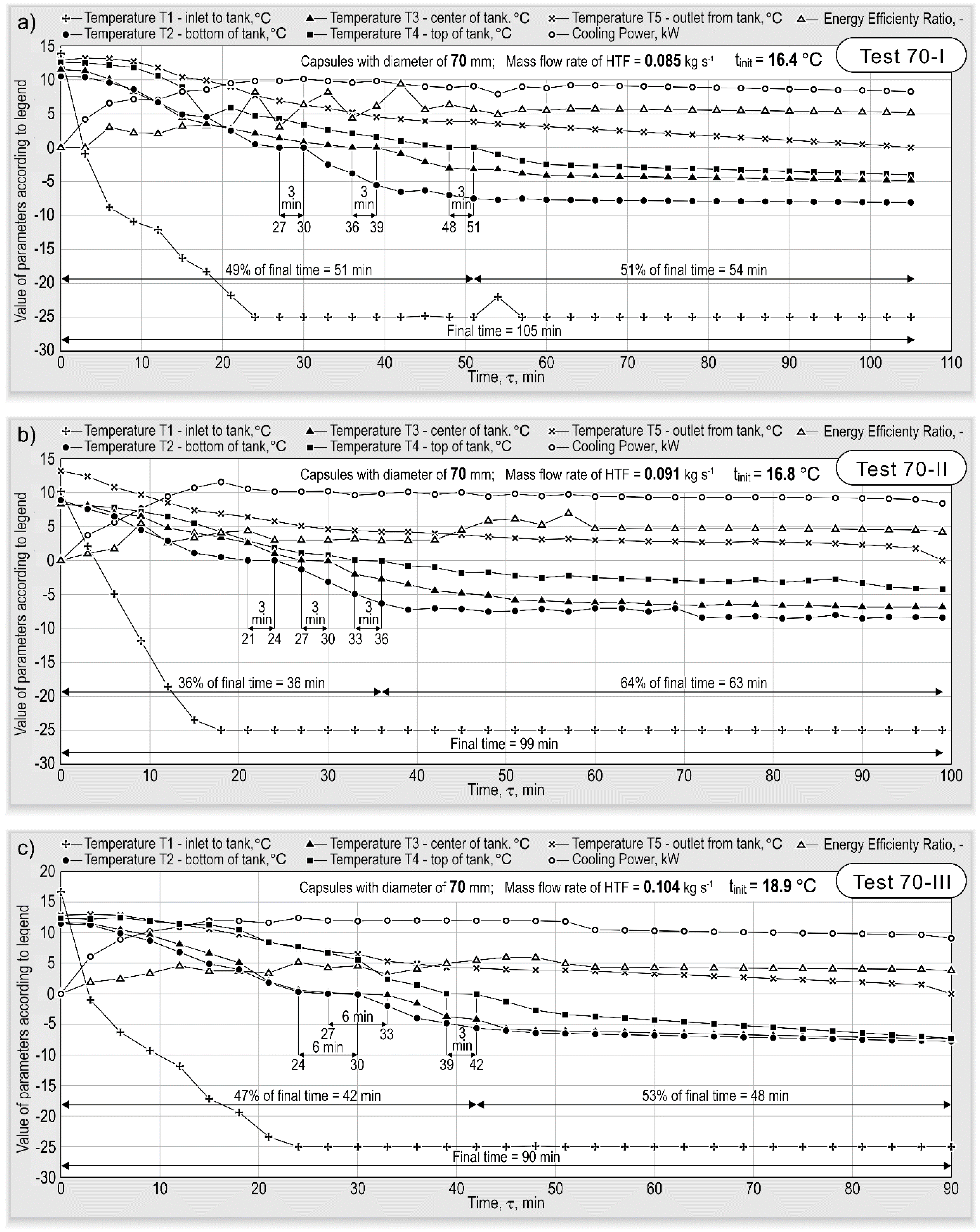
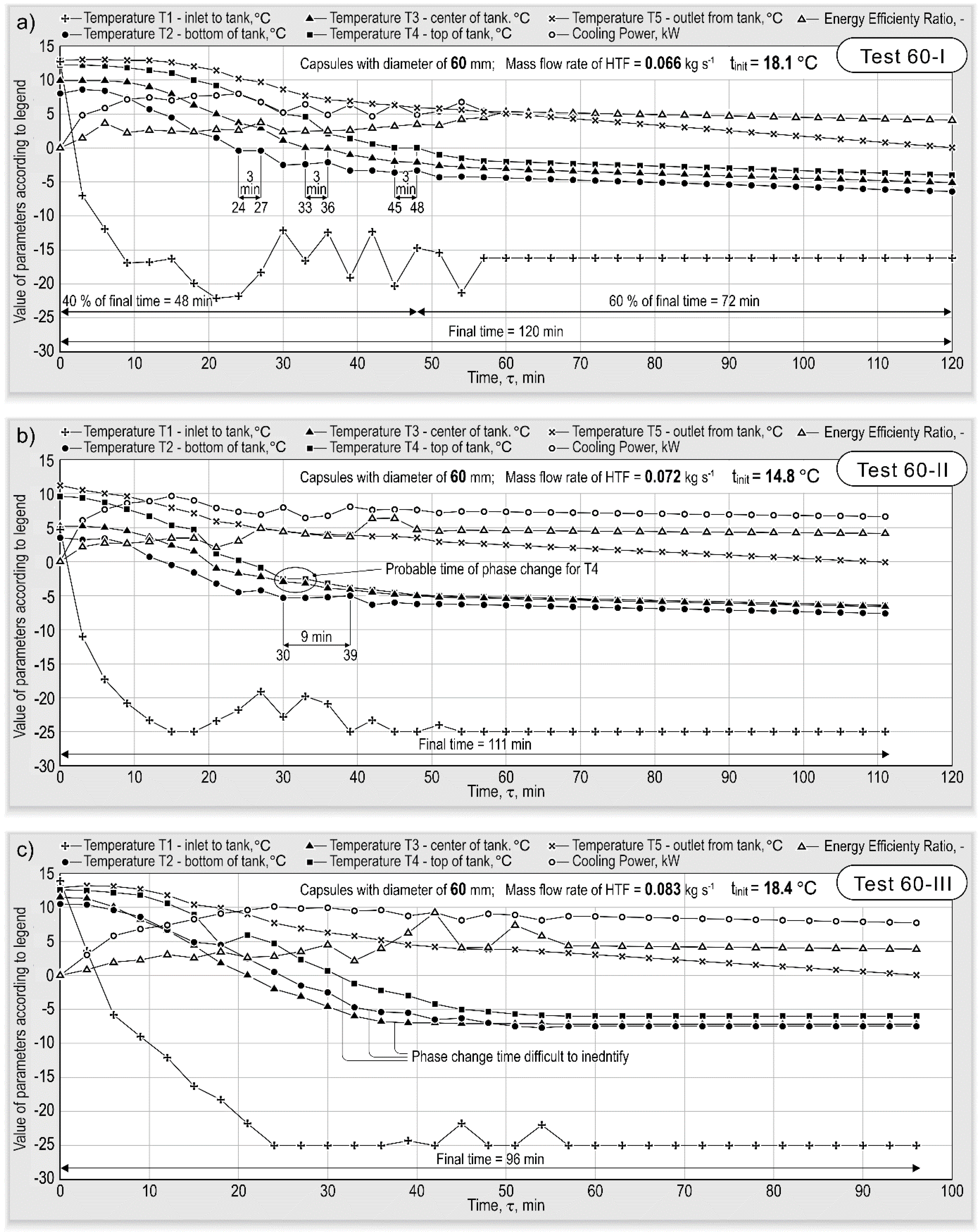
Figure 4, Figure 5 and Figure 6 illustrate the measurement results obtained for the test capsules. The results shown above represent the distribution of the calculated cooling power and energy efficiency ratio as a function of time for the measured temperatures. The measurements do not have the same initial state, i.e., the starting temperature. Therefore, when observing the data presented in Figure 4, Figure 5 and Figure 6, this should be considered. Nevertheless, in the calculation of the obtained effects, i.e., relationships from 1 to 5, different initial test conditions are considered. The character and dynamics of the measured parameters of the accumulator charging process are strongly dependent on the assumed operation parameters of the cold storage installation and the diameter of the capsule used. For all capsule sizes, the increase in the mass flow rate of the heat transfer fluid in the cold storage installation led to a reduction of the time taken to attain the water–ice phase change and equalize the temperature along the height of the cold accumulator. For 70- and 80-mm-diameter capsules, the increase in the HTF mass flow rate also contributed to the more stable operation of the cold accumulator and the heat pump. This was visible in the reduction in the frequency of defrosting the heat pump’s heat exchanger and uniform heat transfer within the whole volume of the storage. That could be observed upon the analysis of variations in the temperature of the water–glycol mixture at the accumulator inlet, the momentary values of the cooling power, or by the frosting of the external accumulator surface (observation conducted after removing the thermal insulation of the accumulator).
In the case of 60-mm-diameter capsules, their smaller mass compared to 70- and 80-mm-diameter capsules made the bed more prone to vibration during the flow of the heat transfer fluid. For 60-mm-diameter spheres, the increase in HTF mass flow rate up to medium and high levels caused intensive vibrations of the capsules. The increase in flow, combined with the intensive vibrations of 60-mm-diameter capsules, did not allow for the thermal stratification of the bed at the time of the water–ice phase change. Strong vibrations in the lower part of the storage tank caused the phase change not to occur from the bottom, i.e., in the foreseen manner, but from the middle of the tank. Vibrations of the capsules in the upper parts of the tank would clearly make the water–ice phase change difficult. The phase change only took place after a cooling time longer than in the case of lower HTF mass flow rate magnitudes. For 80-mm-diameter capsules, the time of the accumulator charging process amounted to 96–120 min.
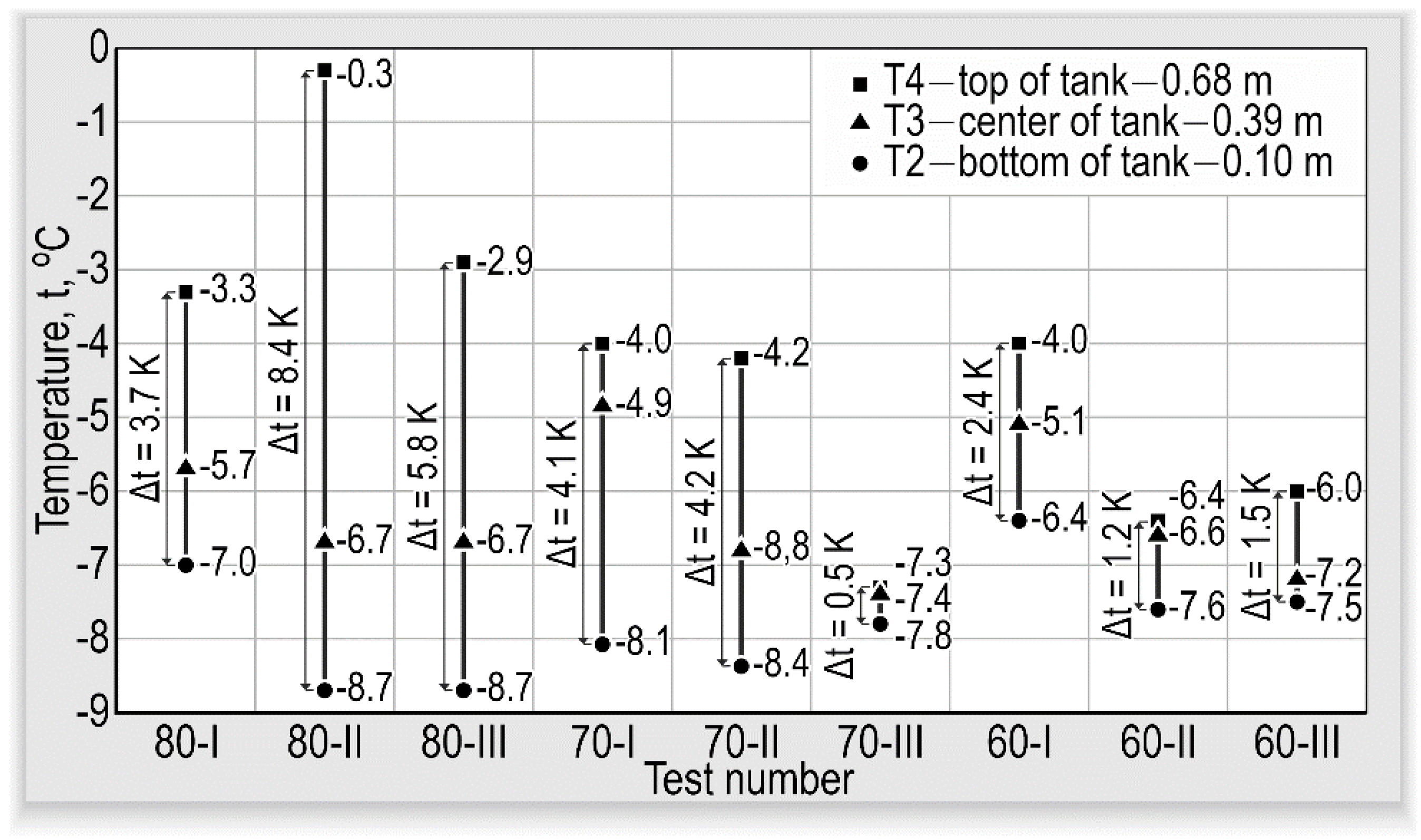
For 70-mm-diameter capsules, the abovementioned time ranged from 90 to 105 min. For 60-mm-diameter capsules, the charging time was comparable to the time of charging the accumulator with the bed of 80-mm-diameter capsules, amounting to 96–120 min. Figure 7 shows the final inside temperature values in selected capsules T2, T3, and T4, obtained from measurements. As shown in Figure 7, the temperatures are below 0 °C. This indicates complete freezing of these capsules.
As can be seen in Figure 7, lower temperature gradients occurred for tests with 60- and 70-mm-diameter capsules. In the majority of the tests, the degree of overcooling of the lower storage tank part also decreased with a reduction in capsule size and increase in the HTF mass flow rate in the accumulator. It should be underlined that the 70-mm-diameter capsules are stiffer, so they did not undergo deformations upon contact with adjacent capsules, as was observed for 80-mm-diameter capsules. The capsules have a wall thickness of about 0.25 mm. This allowed for the initial distance between individual capsules to be maintained. That state led to an increase in the stability of the operation parameters of the cold accumulator. The results obtained in [38] indicated that reducing the shell thickness of encapsulated PCMs is favorable for elevating energy charging rate and energy storage capacity, while it is harmful to mechanical stability. During the tests with 60-mm-diameter capsules, fluctuations in flow and pulsing caused by pressure jumps at the time of bed breakthrough were noted, with accompanying bed movements made by the circulating working fluid. With the increase in flow, the operation was more stable, though some pulsations of, e.g., cooling power. The highest fluid flow stabilized the operation of the accumulator and maintained the stable cooling power. The momentary EER values are very high. This is due to two main factors. First, at the moment of the heat pump going over to a lower speed or defrosting, the uptake of electric energy is low. At the same time, the circulation pump is still operating, forcing the already overcooled HTF into the cold tank. Generally, the inertia of the installation is great. The electric energy consumption by the circulation pump is negligible compared to that of the heat pump. Thus, in the measuring cycle, there is low electric energy consumption with the delivery of a large amount of the overcooled heat transfer fluid. This state translates into a high EER coefficient. Moreover, the EER for the unit (heat pump) is increased relative to the typical parameters of this type of equipment due to extensive modifications to the device itself. In addition, in the periods of high EER values, the heat pump operated at the lowest temperature difference between the lower and the upper energy sources.

3.1.2. The Cooling Power and Capacity of the Accumulator

As per the test results shown in Figure 4, Figure 5 and Figure 6, the highest cooling power values were obtained in tests with 70- and 80-mm-diameter capsules. The obtained cooling powers ranged from 10.1 to 12.4 kW. Their magnitudes increased with the increase in HTF flow. For 60-mm-diameter capsules, the maximum cooling power values amounted to 8–10.1 kW. The highest cooling capacity values were obtained for 80-mm-diameter capsules. They ranged from 15.9 to 16.9 kWh. In this case, the increase in flow in the accumulator resulted in a reduction of the amount of stored cold. For 70-mm-diameter capsules, in spite of the highest values of momentary cooling power, the amount of stored cold amounted to 15.2–16 kWh. In this case, the increase in flow resulted in an increase in the amount of stored cold. Just like for cooling power, the lowest values of stored cold were obtained for measurements with 60-mm-diameter capsules. They ranged from 11 to 13.7 kWh. For that measurement series, the maximum value occurred for the medium HTF flow. With the increase in HTF mass flow, the cooling power increased for all capsule types. For 80-mm capsules, the obtained values were contained in the range from 10.7 to 11.7 kW for low and high flow, respectively. For 70-mm capsules, the obtained cooling power values ranged from 10.1 to 12.4 kW. In the case of 60-mm capsules, the cooling power ranged from 8 to 10.1 kW, also for low and high flow. With reference to the cooling capacity, it is hard to show, at this stage of analysis, the explicit character of variations in this quantity as dependent on the HTF mass flow.

3.1.3. The Energy Efficiency of the Cold Storage Installation

The results show that the highest energy efficiency of cold storage in utilizing the initial heat capacity of the accumulator under investigation was attained for capsules with a diameter of 80 mm: 97%. Just like for cooling power, high cold storage efficiency values were also obtained for 70-mm-diameter capsules. The cold storage efficiency lies in the range from 90% to 92% and grows with the increase in HTF flow. In the case of 60-mm-diameter capsules, the trend of cold storage efficiency is identical to the cooling power. The efficiency values ranged from 66% to 79%, with the maximum values occurring in medium-flow conditions. The authors of [36] achieved the highest accumulator charging efficiencies for 70-mm capsules. However, in spite of differences in the range of the temperature of the process under investigation, both studies, i.e., [36] and ours, yielded comparable final results. A very important parameter defining the energy efficiency is the energy efficiency ratio (EER) of the cold storage installation. It accounts for the energy expenditure incurred for attaining a given energy effect. In the case of the installation under investigation, the effect was the amount of cold possible to store in the given testing conditions. The energy expenditure is the consumption of electric energy for the operation of the heat pump and equipment assisting the work of the test stand (the circulation pump, the supply of measuring sensors). Based on the measurement data, the value of the energy efficiency ratio was calculated to be in the range from 3.5 to 4.9. The highest EER value is exhibited by measurement series for 80- and 70-mm-diameter capsules. As pointed out earlier, this is the result of more stable operation conditions for these two accumulator beds, compared to 60-mm-diameter capsules. The maximum value of 4.9 occurred for 70-mm-diameter capsules at the lowest HTF velocity and for 80-mm-diameter capsules for the highest HTF velocity. The obtained results were regarded as satisfactory. It was also observed that, with the increase in accumulator charging duration, the EER value decreased. The analysis of the obtained results for the energy efficiency of the cold store charging process and the influence of HTF mass flow variations on those results indicated that the change in capsule diameter had a variable effect for each of the bed types. It was also hard to satisfactorily show the repeatability of those relationships.

3.2. Analysis of the Obtained Test Results

To systematize the obtained test results, for their further analysis it was essential to find relationships that would integrate all working conditions of the cold accumulation concept used in the investigation. For this purpose, criterial numbers were indicated, which would adequately reflect the thermal and flow conditions of the cold accumulator and influence its cooling capacity and energy efficiency. For dynamic similarity, the Strouhal number was selected, which characterizes the unsteady mode of flow, and the Reynolds number, which defines the similarity of flow under the action of inertia forces and internal friction forces. For thermal similarity, the Fourier number was chosen, which describes the similarity of the temperature fields of systems with unsteady heat exchange, and the Nusselt number, which expresses the similarity of heat transfer. As mentioned in Section 3.1, the heat and flow conditions and the phase-change phenomenon are very complex under those conditions. The attempts to find explicit, solely single-parameter relationships for the effect of the test parameters on the obtained results were unsatisfactory to the authors, i.e., the analysis of the effect of single criterial numbers on the obtained results was not sufficient. Therefore, wishing to standardize the effect of significant research parameters, the obtained cooling capacities, energy efficiency of cold storage, and energy efficiency ratio of the cold accumulator were represented as a product of criterial numbers (S, Re, Nu, Fo). The abovementioned product is referred to in this paper as the “Research Stand Factor Number” and denoted by RSFN. This denotation is an acronym formed from the initial letters of the criterial numbers. The RSFN is described by this relationship:
R S F N = R e p · S · F o · N u .
The Reynolds number is described by Equation (10), while the other numbers were calculated using Equations (12)–(14):
S = U ϕ , h t f · τ f i n d p
N u = h d p λ = Q c s · d p A · Δ t · λ · τ f i n
F o = λ · τ f i n c p , h t f · ρ h t f · ( d p ) 2 .
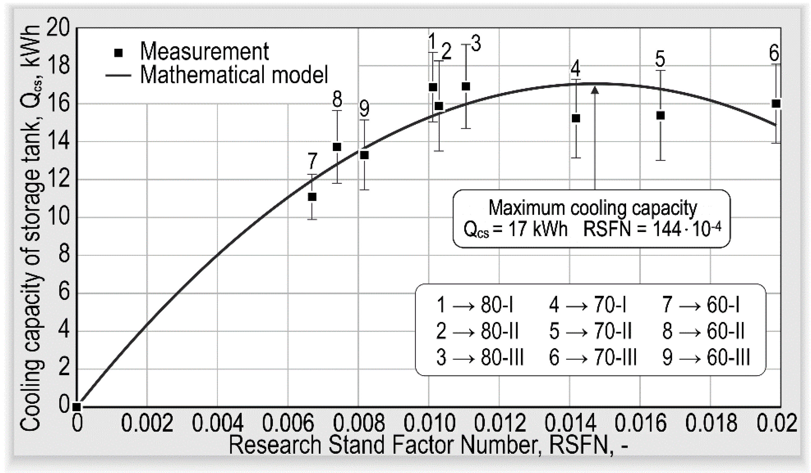
Moreover, using the least squares method, the obtained results were described by mathematical relationships. The greatest values of R2 for the approximation of the measurement results to the significant operational and constructional parameters of the prototype cold accumulator under investigation were exhibited by a functional relationship in the form of a multinomial of the second degree. Figure 8 shows the distribution of the measurement results and the values of the mathematical model of cooling capacity as a function of the operation conditions (RSFN) of the prototype cold accumulator. The value of R2 was 0.99. The obtained results are described by this relationship:
Q c s = 79 , 553 ( R S F N ) 2 + 2328 · R S F N .
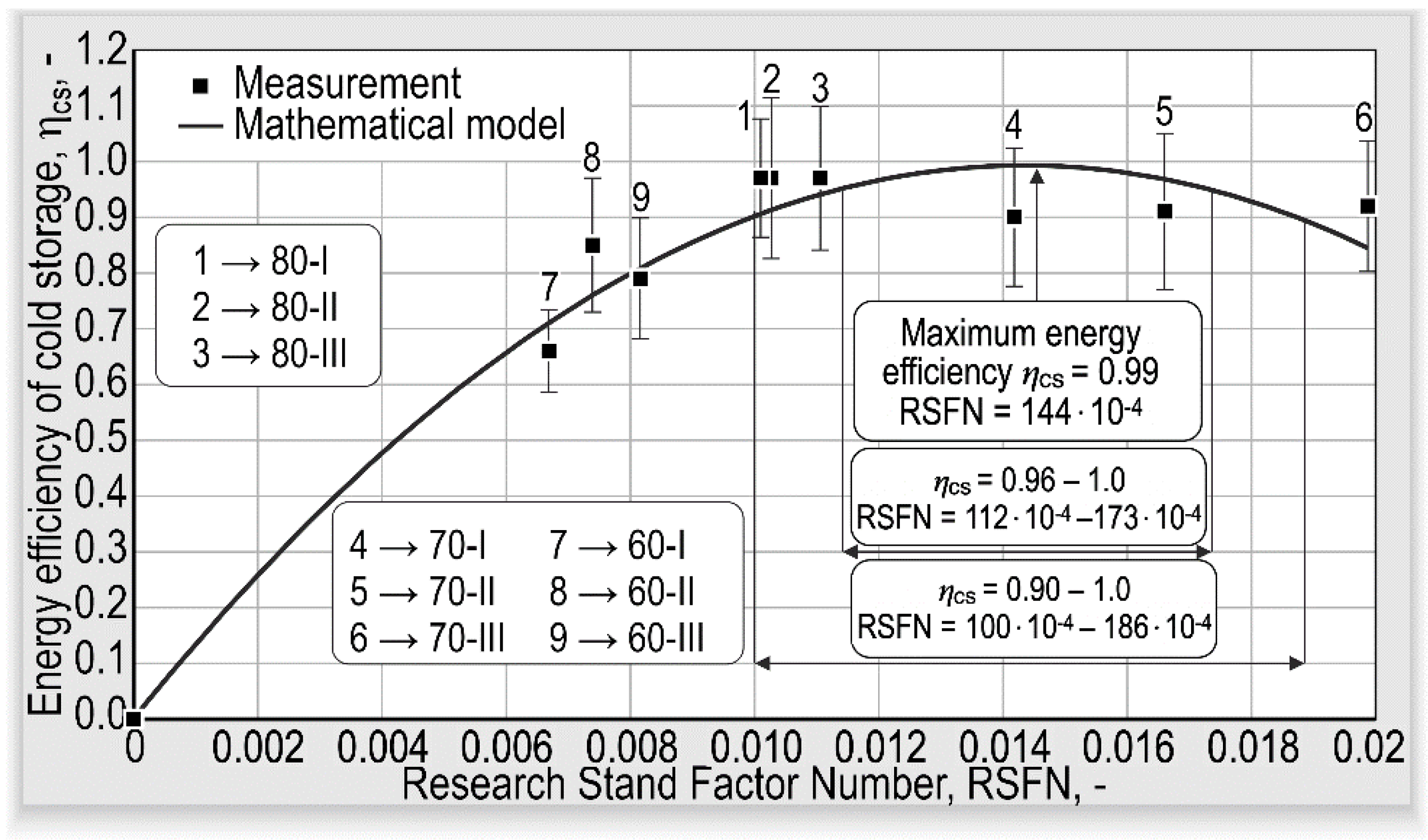
In accordance with the proposed model and considering the measuring error, the maximum value of cooling capacity of 17 kWh was obtained for an RSFN number of 144 · 10 4 . Figure 9 shows the distribution of measurement results and the values of the mathematical model of energy efficiency of cold storage as a function of the operation conditions of the prototype cold accumulator. R2 was 0.99.
The obtained results are described by this relationship:
η c s = 4873.8 ( R S F N ) 2 + 139 · R S F N .
Based on the proposed model, it was found that the maximum cold accumulator charging efficiency could be attained for an RSFN number of 144 · 10 4 . This value amounted to 99%. The range of efficiency for the RSFN number in the range from 100 · 10 4 to 186 · 10 4 will amount to 90%; in the range from 112 · 10 4 to 173 · 10 4 , above 95%; and in the range from 125 · 10 4 to 160 · 10 4 , above 98%. Figure 10 shows the distribution of measurement results and the values of the mathematical model of energy efficiency ratio as a function of the operation conditions of the prototype cold accumulator. R2 was 0.99. The obtained results are described by this relationship:
E E R = 23 , 176 ( R S F N ) 2 + 667 · R S F N .
In accordance with the proposed model and considering the measuring error, the maximum value of EER 4.8 was obtained for an RSFN number of 144 · 10 4 . EER values above 3.0 will be achieved for RSFN numbers greater than 55. To achieve the prototype cold accumulator’s energy efficiency ratio value above 3.5, the RSFN value should be above 68, while achieving an EER value above 4.0 will be possible for an RSFN value in the range from 84 · 10 4 to 210 · 10 4 .

4. Conclusions

The investigations carried out and their analysis have confirmed the possibility of effective cold storage using a water–ice phase change in spherical capsules placed in a cylindrical tank. The results have shown that a storage efficiency of above 90% can be achieved for capsules of diameters of 70 and 80 mm. The highest cooling capacity values were also achieved for 70- and 80-mm-diameter capsules. They amounted to 15.2–16.9 kWh, which yields index values of 76.4 and 84.8 kWh, respectively, per cubic meter of the bed in the prototype accumulator. The energy efficiency ratio (EER) values were in the range from 3.4 to 4.9, whereas for 70- and 80 mm-diameter capsules they were in the range from 3.8 to 4.9. The less advantageous measurement results obtained for 60-mm-diameter capsules resulted chiefly from the lack of temperature stability of the water–glycol mixture, caused by the process of defrosting the heat pump’s heat exchanger and intensive capsule vibrations (pulsations) during the accumulator charging process. These pulsations are due to an attempt to fluidize the 60-mm-diameter capsules inside the accumulator. The capsule vibrations clearly hampered the water–ice phase change. The phase change only occurred after prolonged testing, comparable to the duration of the process of storage charging for 80-mm-diameter capsules. The mathematical relationships developed based on the test results, using criterial numbers for describing the cold accumulator charging process, provide a satisfactorily accurate, useful tool for the assessment of the prototype cold accumulator under investigation. Based on the developed relationships and allowing for measuring error, it has been found that the maximum values of the energy efficiency of cold storage (0.99), cooling capacity (17 kWh), and EER value (4.8) occur for an RSFN value of 144 · 10 4 . These conditions correspond to a bed of 70-mm-diameter capsules and a water–glycol mixture mass flow rate of 0.084 kg/s. Such cold accumulator operation conditions were closest to Test 70-I. The experimental tests also showed that, when using 70-mm-diameter capsules, very stable conditions of cold storage operation could be ensured. The absence of a noticeable problem with cold medium temperature destabilization due to the necessary defrosting of the heat pump’s exchanger and satisfactory temperature gradients along the height of the test accumulator were also noted. No significant problems with the operation of the prototype cold accumulator were found during testing. The adopted assumptions of a low thermal expansion of capsules during phase change and the absence of chemical reactions between the circulating working fluid and the tank’s material and the capsules have also been confirmed.

Author Contributions

Conceptualization, R.S. and P.S.; methodology, R.S.; validation, R.S., P.S.; formal analysis, R.S.; investigation, P.S.; resources, R.S. and P.S.; data curation, R.S. and P.S.; writing—original draft preparation, R.S.; writing—review and editing, R.S.; visualization, R.S.; supervision, R.S.; project administration, R.S.; funding acquisition, R.S. All authors have read and agreed to the published version of the manuscript.

Funding

This research received no external funding.

Institutional Review Board Statement

Not applicable.

Informed Consent Statement

Not applicable.

Data Availability Statement

The data presented in this study are not publicly available due to the preparation of the prototype for implementation.

Acknowledgments

Technical support was provided by KARINO and NEON, Poland.

Conflicts of Interest

The funders had no role in the design of the study; in the collection, analyses, or interpretation of data; in the writing of the manuscript, or in the decision to publish the results.

Nomenclature

Aarea of horizontal section of cold accumulator (m2)
cpspecific heat (J kg−1 K−1)
dpcapsule diameter (m)
EERenergy efficiency ratio (-)
hheat transfer coefficient (W m−2 K−1)
HCTheat capacity of tank (kWh)
Lheat of phase change (J kg−1)
mweight, (kg)
m ˙ mass flow rate (kg s−1)
Namount (number)
Pelelectric energy usage (kWh)
Qcscooling capacity (kWh)
Q ˙ c s cooling power (kW)
ttemperature (°C)
Uvelocity (m s−1)
Vvolume (m−3)
Greek Symbols
Δdifference
εvoidage of bed in cold accumulator (-)
λthermal conductivity (W m−1 K−1)
ηenergy efficiency (-), (%)
ρdensity (kg m−3)
νkinematic viscosity (m2 s−1)
τtime (s or min)
ϕvalue based on multicapsule bed
Subscripts
Aaccumulator
cscold storage
finfinal, total
htfheat transfer fluid in installation
iice
ininlet—T1
initstart of test
ivinstantaneous value related to the length of the measuring interval
outoutlet—T5
pcapsule
pcwater–ice phase change
sfsuperficial
wwater
Abbreviations
HTFheat transfer fluid
PCMphase-change material
RSFNResearch Stand Factor Number
Dimensionless numbers
FoFourier number
NuNusselt number
RepReynolds number based on capsule diameter
ReϕReynolds number based on multicapsule bed
SStrouhal number

References

  1. Asgharian, H.; Baniasadi, E. Experimental and numerical analyses of a cooling energy storage system using spherical capsules. Appl. Therm. Eng. 2019, 149, 909–923. [Google Scholar] [CrossRef]
  2. Cerezo, J.; Lara, F.; Romero, R.J.; Rodríguez, A. Analysis and Simulation of an Absorption Cooling System Using a Latent Heat Storage Tank and a Tempering Valve. Energies 2021, 14, 1376. [Google Scholar] [CrossRef]
  3. Mongibello, L.; Graditi, G. Cold Storage for a Single-Family House in Italy. Energies 2016, 9, 1043. [Google Scholar] [CrossRef] [Green Version]
  4. Prabakaran, R.; Sidney, S.; Mohan Lal, D.; Selvam, C.; Harish, S. Solidification of Graphene-Assisted Phase Change Nanocomposites inside a Sphere for Cold Storage Applications. Energies 2019, 12, 3473. [Google Scholar] [CrossRef] [Green Version]
  5. Qureshi, W.A.; Nair, N.-K.C.; Farid, M.M. Impact of energy storage in buildings on electricity demand side management. Energy Convers. Manag. 2011, 52, 2110–2120. [Google Scholar] [CrossRef]
  6. Avghad, S.N.; Keche, A.J.; Kousal, A. Thermal energy storage: A review. J. Mech. Civ. Eng. 2016, 13, 72–77. [Google Scholar]
  7. Basecq, V.; Michaux, G.; Inrad, C. Short-term storage systems of thermal energy for buildings: A review. Adv. Build. Energy Res. 2013, 7, 66–119. [Google Scholar] [CrossRef]
  8. Mehling, H.; Cabeza, L.F. Heat and Cold Storage with PCM. An Up to Date Introduction into Basic and Applications; Springer: Berlin/Heidelberg, Germany, 2008. [Google Scholar]
  9. Chaiyat, N. Energy and economic analysis of a building air-conditioner with a phase change material. Energy Convers. Manag. 2015, 94, 150–158. [Google Scholar] [CrossRef]
  10. Allouche, Y.; Varga, S.; Bouden, C.; Oliveira, A.C. Experimental determination of the heat transfer and cold storage characteristics of a microencapsulated phase change material in a horizontal tank. Energy Convers. Manag. 2015, 94, 275–285. [Google Scholar] [CrossRef]
  11. Rahdar, H.H.; Emamzadeh, A.; Ataei, A. A comparative study on PCM and ice thermal energy storage tank for air- conditioning systems in office buildings. Appl. Therm. Eng. 2016, 96, 391–399. [Google Scholar] [CrossRef]
  12. Souayfane, F.; Fardoun, F.; Biwole, P.H. Phase change materials (PCM) for cooling applications in buildings: A review. Energy Build. 2016, 129, 396–431. [Google Scholar] [CrossRef]
  13. Pardinńas, Á.Á.; Alonso, M.J.; Diz, R.; Kvalsvik, K.H.; Fernández-Seara, J. State-of-the-art for the use of phase-change materials in tanks coupled with heat pumps. Energy Build. 2017, 140, 28–41. [Google Scholar] [CrossRef] [Green Version]
  14. Ma, Z.; Ren, H.; Lin, W. A review of heating, ventilation and air conditioning technologies and innovations used in solar-powered net zero energy Solar Decathlon houses. J. Clean. Prod. 2019, 240, 118158. [Google Scholar] [CrossRef]
  15. Tola, V.; Arena, S.; Cascetta, M.; Cau, G. Numerical Investigation on a Packed-Bed LHTES System Integrated into a Micro Electrical and Thermal Grid. Energies 2020, 13, 2018. [Google Scholar] [CrossRef] [Green Version]
  16. Zender-Świercz, E. A Review of Heat Recovery in Ventilation. Energies 2021, 14, 1759. [Google Scholar] [CrossRef]
  17. Cervera-Vazquez, J.; Montagud-Montalava, C.; Corberan, J.M. Sizing of the buffer tank in chilled water distribution air-conditioning systems. Sci. Technol. Built Environ. 2016, 22, 290–298. [Google Scholar] [CrossRef] [Green Version]
  18. Guo, L.; Ye, H. Numerical and Experimental Study on a High-Power Cold Achieving Process of a Coil-Plate Ice-Storage System. Energies 2019, 12, 4085. [Google Scholar] [CrossRef] [Green Version]
  19. Kang, Z.; Wang, R.; Zhou, X.; Feng, G. Research Status of Ice-storage Air-conditioning System. Procedia Eng. 2017, 205, 1741–1747. [Google Scholar] [CrossRef]
  20. Chung-Tai, W.; Chih-Ling, F.; Yao-Hsu, T. Application of an ice thermal energy storage system as ways of energy management in a multi-functional building. J. Renew. Sustain. Energy 2015, 7, 1–7. [Google Scholar]
  21. Patent. Storage Tank Device for an Energy Storage System and Energy Storage System with a Storage Tank Device. Available online: https://patents.google.com/patent/DE102010037474A1/de (accessed on 5 April 2021).
  22. Hollmuller, P.; De Oliveira, F.; Graf, O.; Thiele, W. Solar assisted heat pump with ice storage for a 19,000 m2 retrofitted multi-family building complex. Energy Procedia 2017, 122, 271–276. [Google Scholar] [CrossRef]
  23. Davies, T.W. Slurry ice as a heat transfer fluid with a large number of application domains. Int. J. Refrig. 2005, 28, 108–114. [Google Scholar] [CrossRef]
  24. Waquas, A.; Ud Din, Z. Phase change material (PCM) storage of free cooling of buildings—A review. Renew. Sustain. Energy Rev. 2013, 18, 607–625. [Google Scholar] [CrossRef]
  25. Moreno, P.; Solé, C.; Castell, A.; Cabeza, L.F. The use of phase change materials in domestic heat pump and air-conditioning system for short term storage: A review. Renew. Sustain. Energy Rev. 2014, 39, 1–13. [Google Scholar] [CrossRef]
  26. Oró, E.; de Gracia, A.; Castell, A.; Farid, M.M.; Cabeza, L.F. Review on phase change materials (PCMs) for cold thermal energy storage applications. Appl. Energy 2012, 99, 513–533. [Google Scholar] [CrossRef] [Green Version]
  27. Podara, C.V.; Kartsonakis, I.A.; Charitidis, C.A. Towards Phase Change Materials for Thermal Energy Storage: Classification, Improvements and Applications in the Building Sector. Appl. Sci. 2021, 11, 1490. [Google Scholar] [CrossRef]
  28. Raj, V.A.; Velraj, R. Review on free cooling of buildings using phase change materials. Renew. Sustain. Energy Rev. 2010, 14, 2819–2829. [Google Scholar] [CrossRef]
  29. Farid, M.M.; Khudhair, A.M.; Razack, S.A.K.; Al-Hallaj, S. A review on phase change energy storage: Materials and applications. Energy Convers. Manag. 2004, 45, 1597–1615. [Google Scholar] [CrossRef]
  30. Peng, G.; Dou, G.; Hu, Y.; Sun, Y.; Chen, Z. Phase Change Material (PCM) Microcapsules for Thermal Energy Storage. Adv. Polym. Technol. 2020. [Google Scholar] [CrossRef]
  31. Zalba, B.; Marin, J.M.; Cabeza, L.F.; Mehling, H. Review on thermal energy storage with phase change: Materials, heat transfer analysis and applications. Appl. Therm. Eng. 2003, 23, 251–283. [Google Scholar] [CrossRef]
  32. Pasupathy, A.; Velraj, R.; Seeniraj, R.V. Phase change material-based building architecture for thermal management in residential and commercial establishments. Renew. Sustain. Energy Rev. 2008, 12, 39–64. [Google Scholar] [CrossRef]
  33. Medved, S.; Arkar, C. Correlation between the local climate and free-cooling potential of latent head storage. Energy Build. 2008, 40, 429–437. [Google Scholar] [CrossRef]
  34. Genc, A.M.; Karadeniz, Z.H.; Ekren, O.; Toksoy, M. A Novel Spherical Packed Bed Application on Decentralized Heat Recovery Ventilation Units. E3s Web Conf. 2019, 111, 01012. [Google Scholar] [CrossRef] [Green Version]
  35. Kalaiselvam, S.; Parameshwaran, R. Thermal Energy Storage Technologies for Sustainability. Systems Design, Assessment and Applications, Chapter 5—Latent Thermal Energy Storage, 1st ed.; Academic Press: Cambridge, MA, USA, 2014; pp. 83–126. [Google Scholar]
  36. Guo, H.; ELSihy, E.S.; Liao, Z.; Du, X. Comparative Study on the Performance of Single and Multi-Layer Encapsulated Phase Change Materials Packed-Bed Thermocline Tank. Energies 2021, 14, 2175. [Google Scholar] [CrossRef]
  37. Yang, W.-C. Flow Through Fixed Beds. In Handbook of Fluidization and Fluid-Particle Systems, 1st ed.; Yang, W.-C., Ed.; Marcel Dekker, Inc.: New York, NY, USA, 2003; pp. 39–62. [Google Scholar]
  38. Yu, Q.; Romagnoli, A.; Al-Duri, B.; Xie, D.; Ding, Y.; Li, Y. Heat storage performance analysis and parameter design for encapsulated phase change materials. Energy Convers. Manag. 2018, 157, 619–630. [Google Scholar] [CrossRef]
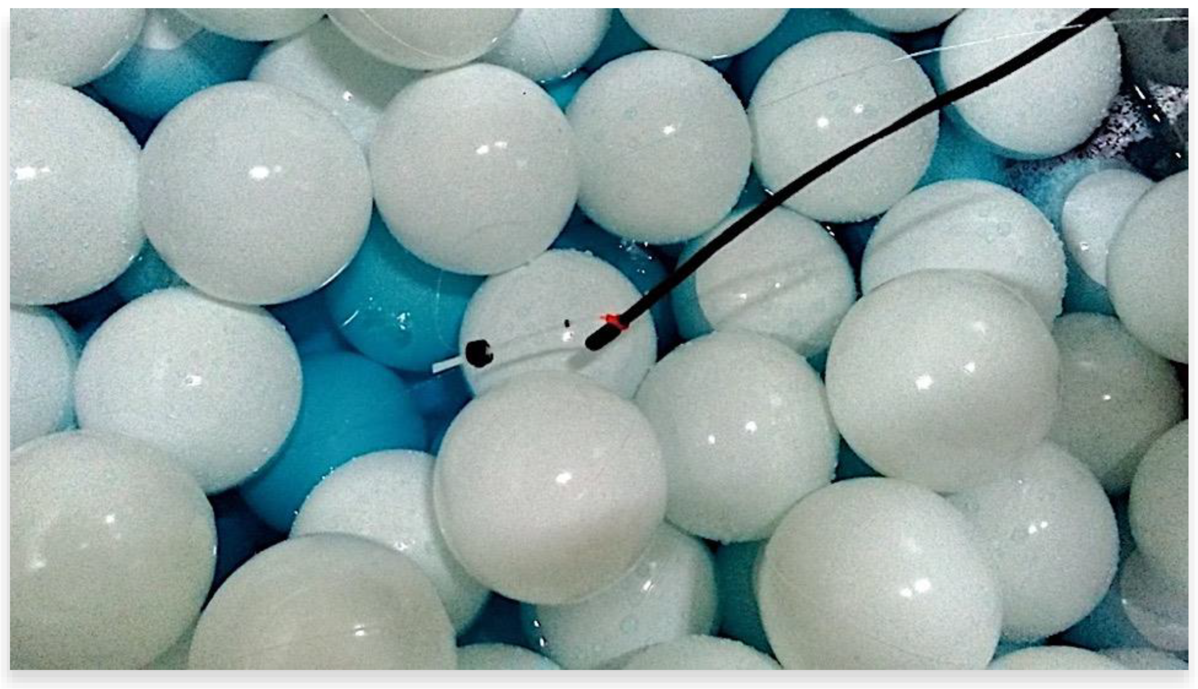
Figure 1. The inside of the cold accumulator with a bed of spherical capsules.
Energies 14 02703 g001
Figure 2. A view of the testing stand.
Energies 14 02703 g002
Figure 3. A schematic diagram of the test stand.
Energies 14 02703 g003
Figure 4. Measurement results: distribution of temperatures, cooling power, and energy efficiency ratio as a function of time for 80-mm-diameter capsules: (a) Test 80-I; (b) Test 80-II; (c) Test 80-III.
Energies 14 02703 g004
Figure 5. Measurement results: distribution of temperatures, cooling power, and energy efficiency ratio as a function of time for 70-mm-diameter capsules: (a) Test 70-I; (b) Test 70-II; (c) Test 70-III.
Energies 14 02703 g005
Figure 6. Measurement results: distribution of temperatures, cooling power, and energy efficiency ratio as a function of time for 70-mm-diameter capsules: (a) Test 60-I; (b) Test 60-II; (c) Test 60-III.
Energies 14 02703 g006
Figure 7. The final value of temperature in capsules for measurement points T2, T3, and T4.
Energies 14 02703 g007
Figure 8. Distribution of measurement results and the values of the mathematical model of cooling capacity as a function of the operation conditions of the prototype cold accumulator.
Energies 14 02703 g008
Figure 9. Distribution of measurement results and the values of the mathematical model of energy efficiency of cold storage as a function of the operation conditions of the prototype cold accumulator.
Energies 14 02703 g009
Figure 10. Distribution of measurement results and the values of the mathematical model of energy efficiency ratio as a function of the operation conditions of the prototype cold accumulator.
Energies 14 02703 g010
Table 1. The characteristic parameters of the water–glycol mixture used as a heat transfer fluid in the test installation: 33% water solution of propylene glycol.
ParameterValue
Density,
ρf (kg m−3)
1053
Specific heat,
cp,f (kJ kg−1 K−1)
3.66
Thermal conductivity,
λ (W m−1 K−1)
0.404
Kinematic viscosity,
ν (m2 s−1)
0.0000124
Table 2. Description of the experimental tests.
No.TestCapsule Diameter, dp (mm)Mass Flow Rate of HTF m f ˙   ( kg   s 1 )
DescriptionValue
180-I80lowest flow0.076
280-II80medium flow0.084
380-III80highest flow0.089
470-I70lowest flow0.084
570-II70medium flow0.091
670-III70highest flow0.104
760-I60lowest flow0.066
860-II60medium flow0.072
960-III60highest flow0.083
Table 3. Basic operational parameters of the testing stand.
No.ParameterTest
80-I80-II80-III70-I70-II70-III60-I60-II60-III
1Voidage of bed,
ε (-)
0.460.510.46
2Superficial fluid velocity,
U s f , h t f · 10 3 (m s−1)
0.280.310.330.310.340.390.250.270.31
3Fluid velocity based on multicapsule bed,
U ϕ , h t f · 10 4 (m s−1)
0.890.981.041.251.361.550.750.810.94
4Rep, (-)1.832.022.141.761.912.191.191.301.50
5Reϕ, (-)0.570.630.670.710.770.880.360.390.45
Publisher’s Note: MDPI stays neutral with regard to jurisdictional claims in published maps and institutional affiliations.