Article

Implementation of Distributed Autonomous Control Based Battery Energy Storage System for Frequency Regulation

1
OCI Power Co. Ltd., Jung-gu, Seoul 04532, Korea
2
Department Electrical Engineering, Myongji University, Yongin-si 17058, Korea
3
Department of Electrical and Computer Engineering, University of Michigan-Dearborn, Dearborn, MI 48128, USA
*
Author to whom correspondence should be addressed.
Energies 2021, 14(9), 2672; https://doi.org/10.3390/en14092672
Submission received: 9 April 2021 / Revised: 26 April 2021 / Accepted: 28 April 2021 / Published: 6 May 2021

Abstract

:
It has been mandated that 5% of the generation capacity of conventional fossil fuel power plants shall be used exclusively for frequency regulation (FR) purposes in South Korea. However, the rotational speed of generators cannot be controlled quickly, and thus the variation in the power generation for FR takes some time. Even during this short period of time, frequency fluctuations may occur, and the frequency may be out of range of its reference value. In order to overcome the limitations of the existing FR method, 374 MW (103 MWh) battery energy storage systems (BESSs) for FR have been installed and are in operation at 13 sites in South Korea. When designing the capacity of BESS for FR, three key factors, i.e., the deployment time, duration of delivery, and end of delivery, are considered. When these times can be reduced, the required capacity for BESS installation can be decreased, achieving the same operational effects with minimal investment in the facilities. However, because a BESS for FR (FR BESS) needs to be installed under a large capacity, providing a single output, a centralized control method is employed. The centralized control method has the advantage of being able to view and check the entire system at once, although in the case of FR BESS, a novel system design that can optimize the above three factors through a faster and more accurate control is required. Therefore, this paper proposes the implementation of a distributed autonomous control-based BESS for frequency regulation. For the proposed FR BESS, the central control system is responsible for the determination of external factors, e.g., power generation/demand forecasting; and the system is designed such that the optimal control method of renewable energy sources and BESS according to real-time frequency variations during practical operation is determined and operated using a distributed autonomous control method. Furthermore, this study was verified through the simulation that the proposed distributed autonomous control method conducts FR faster than an FR BESS with conventional centralized control, leading to an increase in the FR success rate, and a decrease in the deployment time required (e.g., 200 ms).

Graphical Abstract

1. Introduction

With the adoption of decarbonization, decentralization, and digitalization, the power industry is entering a period of energy transition [1]. In terms of power technology, the key factor that triggered the energy transition was the distributed energy resource (DER). With the development of power electronics technology-based renewable generations, e.g., photovoltaic generation and wind turbines, and energy storage systems using batteries, the power industry is now facing new challenges and opportunities. Therefore, research related to DER such as fuel cell, renewable energy, energy storage, etc. has been actively conducted in recent years [2,3,4,5].
In the power industry, a battery energy storage system (BESS) is generally composed of four components: power receiving and distribution facilities, a power conditioning system (PCS), batteries, and a power management system (PMS). A BESS can be used for various purposes in the power industry because it can store a large capacity of electric energy in a battery and use the stored energy at the desired power quality whenever it is needed. Sandia National Laboratories defined 16 types of methods and proposed detailed applications utilizing BESS [6].
A BESS for frequency regulation (FR BESS) used for stabilizing the transmission system is one of the representative examples among the various available methods of using a BESS. FR is a highly sensitive and important issue with the highest priority in the transmission system, and the power generation needs to respond quickly according to the change of demand to meet the balance of supply and demand. However, the existing methods of power generation using rotational inertia of the conventional generators have the difficulty of not being able to respond quickly. By contrast, a BESS is capable of a fast response using power electronics technology and is considerably effective for the purpose of FR.
An FR BESS is generally installed in a substation and is built using a PCS of several tens of megawatts in capacity and batteries of several tens of megawatt-hours. Due to its large capacity, a large number of PCSs and batteries need to be operated, and a high-specification system environment and power control technology are required for a fast response. In particular, because fast switching between charging and discharging needs to be conducted according to the supply and demand while monitoring the real-time change in a transmission system, an elaborate technology that controls multiple BESSs during synchronization is required. For instance, FR BESSs have been built and are in operation in 13 substations with a capacity scale of a 376-MW PCS and 103 MWh in South Korea [7,8]. As it was the first operational system in the FR BESS project in South Korea, a high standard operating environment was established. In the second and third rounds of the projects, the optimization of the system operating environment of the FR BESS has been investigated.
As previous studies related to an FR BESS, researchers have adopted stage-of-charge (SoC) control techniques for an operational efficiency improvement and optimization [9,10,11,12], considered various operating factors, e.g., an aggregated BESS and demand-responsive (DR) resources [13,14,15], and conducted research based on the operation of large-capacity FR [16,17,18,19] research related to participation in the power exchange market [20], and operation research focusing on battery life management [21]. Optimization studies have been conducted (e.g., design capacity, economic efficiency, links with various systems, and lifetime management of the facilities) upon the results of the operational effectiveness of an FR BESS. However, these previous studies were based on an operation system with a centralized control method, and research on an operation optimization of an FR BESS from a novel perspective and based on operation experience with a distributed control structure is required based on an operating environment with active autonomous control.
Therefore, this paper proposes the implementation of a distributed autonomous control-based BESS for frequency regulation. The proposed FR BESS has an enhanced operational efficiency through a distributed control method for multiple PCSs, and autonomous control technology has been implemented for the application of a distributed control method in areas other than those requiring centralized control. The proposed system employs a distributed autonomous control method for the optimization of the operating environment of an FR BESS. The proposed distributed autonomous control method will handle the core applications that require system prediction in advance by considering the entire system in a centralized method, whereas it manages real-time-based operations with autonomous controls in a distributed structure. In this way, a faster and improved FR can be achieved. In addition, resiliency can be secured through the proposed distributed structure when communication failure occurs, and battery management failure can be prevented through priority determination.
In the remainder of this paper, Section 2 introduces the existing implementation of BESS for frequency regulation, and Section 3 describes the proposed FR BESS with distributed autonomous control. Section 4 verifies the effectiveness of the proposed system by comparing the operating effect of the proposed FR BESS and a conventional FR BESS. The conclusions and recommendations for future work are given in Section 5.

2. Existing Implementation of BESS for Frequency Regulation

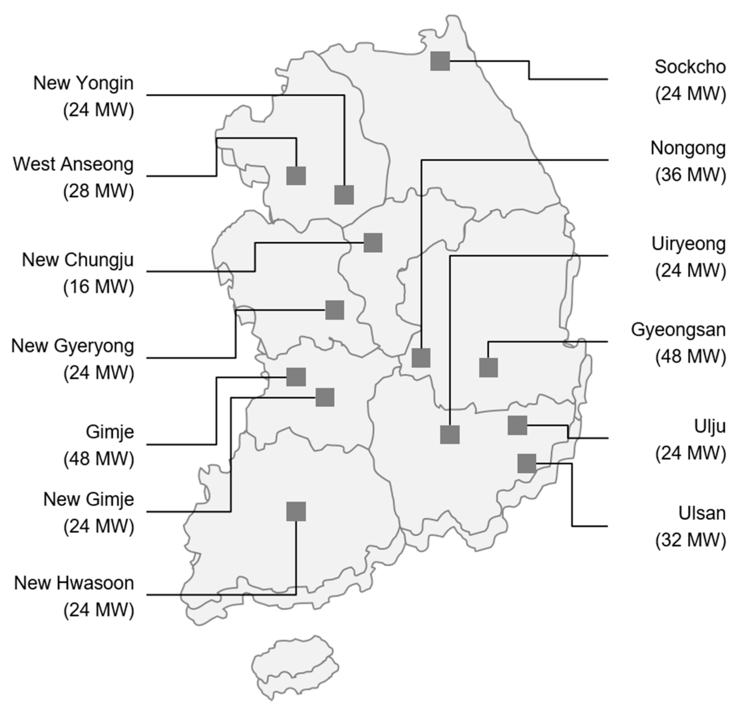
2.1. Projects of the BESS for Frequency Regulation in South Korea

To accommodate the increasing demand for electricity, most plans for the additional construction or expansion of power plants have been reviewed. However, the demand for electricity at peak level arises only a handful of times per year, and to meet such demands, the cost of the additional construction of power plants and the utilization efficiency of power generation facilities have emerged as issues. If an FR BESS can be utilized as a means to resolve this problem, the utilization rate of power generation facilities can be increased in a time- and cost-effective manner, and without having to additionally construct power generation facilities, a reliable balance between the supply and demand can be achieved through the employment of a BESS.
An FR BESS in South Korea is operated for the purposes illustrated in Figure 1. To use 5% of the total power generation for FR based on a power plant with a 500 MW capacity, the power output is limited to 95% under normal conditions. Therefore, if 25-MW capacity is installed using an FR BESS, the capacity of the generator can be utilized at 100%. An FR BESS installed in South Korea has a capacity of 376 MW and is evaluated as having the equivalent effect of building a new power plant with the corresponding capacity. In addition, a stable FR can be achieved through a fast response in comparison to the existing power plants, and an FR BESS also benefits the environment in terms of reducing the CO2 footprint.
Figure 2 shows 13 sites where FR BESSs are installed in South Korea. The total generation capacity is 376 MW, which is the same as the PCS capacity of a BESS, and batteries with a capacity of 103 MWh with a 4 C-rate or higher have been installed through an operation simulation of each FR BESS. The response rate of each FR BESS according to the transient phenomenon at 60 Hz is configured to reach 130 ms [7,8].

2.2. Requirement of BESS for Frequency Regulation

Table 1 outlines the status of the frequency operation of the transmission system in South Korea for 1 month in December 2013. The reference frequency for FR in South Korea is 60 ± 0.2 Hz under normal conditions. When controlled according to this reference value, FR is accurately applied, almost within ±0.1 Hz in practice. A high margin capacity of fossil fuel generators has been secured for frequency regulation, and have been replaced with a BESS, contributing to an increase in the power generation.
The effect of FR using a BESS is generally determined based on the deployment time, duration of delivery, and end of delivery [22]. The deployment time refers to the time during which the power source can respond according to the frequency variation. As the frequency is regulated within the range of 0.2 Hz/s, the dynamic reserve must be deployed as quickly as possible, i.e., within 1 s at most. Therefore, if conventional fossil fuel generators are used, a fast deployment may be difficult owing to the inertia. To address this difficulty, the margin capacity needs to be secured in multiple generators such that multiple units can respond incrementally and the deployment time can be reduced. The duration of the delivery refers to the duration of the power supply for FR. The dynamic reserves must be supplied at least until the power deviation is completely offset by the primary control, i.e., until the frequency nadir is reached. The end of delivery refers to the instantaneous discontinuation of the power supply when the frequency falls within the target frequency range during FR. The end of delivery must be progressive to smooth the transfer from the generators for FR and to avoid creating any sudden imbalance in a weakened system.
An FR BES facilitates a faster deployment because the power output can respond within a few ms from zero to the peak value, and the deployment time, duration of delivery, and end of delivery are achieved with a smaller capacity compared to that using existing fossil fuel generators. Utilizing the fast response rate of a BESS, with a shorter deployment time, when a sufficient duration of delivery can be secured using an adequate battery capacity and the frequency can be regulated through a precise end of delivery, a higher capacity power generation can be secured from conventional fossil fuel generators in comparison to the existing BESS capacity. Therefore, from the perspective of the transmission system operator, if an FR BESS is optimized and installed, the overall system construction cost is reduced in terms of securing the total power generation, and the success rate of FR can be improved.

2.3. Configuration and Operation of the BESS for Frequency Regulation

As a single PCS capacity has physical limitations, it must be implemented through a distribution in appropriate capacity units. The PCS used for a commercial BESS is currently configured using a 2-MVA single-capacity facility. Therefore, when an FR BESS is constructed with a capacity of 20 or 30 MW, 10 or 15 PCS are installed, and a PCS with a capacity of 4 MVA is generally installed and operated for a 40-ft container, and batteries are installed by distributing them into an appropriate capacity for each PCS.
As shown in Figure 3, an FR BESS is operated through a frequency regulation controller (FRC) for each BESS using a frequency regulation control management (FRCM) system [7,8]. According to the real-time system frequency variations, the FRC is operated by distributing the total amount of charge/discharge equally to the given number of FRCs. The SoC of each BESS is transmitted to the FRCM in real time, and the FRCM has the authority to control different charge/discharge commands depending on the SoC.
In general, assuming that the battery SoC is the same and all facilities are in a normal state, the charge/discharge capacity of the BESS is controlled equally, but the battery SoC of a specific BESS may differ depending on the maintenance status of the BESS or a specific situation. Accordingly, the FRCM determines whether to participate in FR or operate separately for securing the SoC based on a comprehensive consideration of the status of the FRCs. As can be seen above, the centralized control method has an advantage in that stable management of the entire system is possible, but when various calculations are conducted, an additional time is required for the determination of the FRCM and the response according to the command, which may lead to a time delay in FR.

3. BESS for a Frequency Regulation through a Distributed Autonomous Control

3.1. Concept of Proposed Distribution Autonomous Control for BESS

Section 2 introduced the current status of an FR BESS installed by KEPCO (a utility company, transmission system operator (TSO)) of South Korea. However, because only a BESS was used, an economic feasibility analysis is necessary for utilization as a commercial BESS in terms of the power exchange. The FR method with a BESS alone is a business mainly promoted by utility companies; however, from the viewpoint of securing resources for the system operation of business providers through a private investment, further consideration of the economic feasibility is required.
As businesses involved in FR have to pay the associated cost to the utility company for a charging BESS, securing the economic feasibility depending on the power generation unit price and lifetime management of the BESS is critical to the decision. Therefore, for FR, private businesses often consider a market participation method using renewable generation when the price is favorable on the power exchange market. If renewable sources are used, the operating ratio of the BESS can be lowered, which is economically advantageous. However, the operation of a BESS involves more difficulty than the operation of a utility applying a control method because the variation in the power generation output of the renewable generation needs to be considered in combination.
If a BESS is charged/discharged by participation in the FR market while controlling the power output characteristics of various types of renewable energy sources, the operation method of a BESS becomes complicated. Therefore, if an FR BESS is operated with the existing centralized control method, the deployment time increases and a BESS with a larger capacity may be required. As this serves as a factor degrading the economic feasibility, a more complex method incorporating distributed and autonomous control should be employed, thereby reducing the dependency on the centralized control method and achieving improvements in terms of the deployment time, duration of delivery, and end of delivery time.
Figure 4 shows the concept of the proposed system for the FR method. When the reference frequency is set to ±0.2 Hz, an FR BESS is designed to start operation at ±0.1 Hz. When the frequency reaches 60.1 Hz based on the renewable generation output that has been previously forecasted, the output of the renewable energy sources and the transmission system power are combined together to charge the BESS. When the frequency falls below 60.1 Hz, the BESS stops charging and switches to standby mode. In this case, the BESS is operated by switching among the charging/discharging/standby modes according to the forecasting of renewable generation and the current situation. Thereafter, when the frequency is lowered to 59.9 Hz, the power output of renewable energy sources and that of the BESS are combined for the power supply. The variable power output of renewable energy sources is supplied with a larger capacity and faster rate through a fast response of the BESS for FR. In this way, (1) more power can be utilized, and a faster response is made possible through the control of the charging/discharging, which reduces the deployment time, (2) the power generation of the renewable energy sources is utilized, minimizing the operation of the battery, which will contribute to a longer duration of delivery, and (3) with the incorporation of a direct control method of renewable energy sources and the SoC management of the BESS, an effective end of delivery operation can be achieved.
To this end, this study proposes a system configuration using a distributed energy resource controller (DERC) that considers both the power output control of the renewable energy sources as well as the BESS by upgrading the FRC function. The proposed system has an advantage of adding a BESS and renewable energy sources to the commercial FR market, and according to the characteristics of the distributed control system, the mutual state is recognized through real-time communication between DERCs, and an autonomous response control technology is applied to the DERC units.
Figure 5 shows the configuration of a DERC-based distributed system. As a difference from the existing approach, while minimizing the dependence on the central system, the proposed system obtains information directly from the adjacent DERC and autonomously applies FR for a set condition, while also utilizing renewable energy sources. In addition, the EMS, a central system, establishes plans only for those upon forecasting, and the PMS only applies real-time responses to abnormalities. Whereas a conventional FRC executes commands from the center only, the proposed DERC autonomously manages optimal distributed energy resources with a real-time exchange of information with other DERCs based on the pre-planned operation information. While controlling the change in renewable generation output with a BESS, when discharging for FR, BESS power generation is added to the renewable generation. In addition, when charging for FR, both the power output of renewable energy sources and the energy from the system are used for charging. In this case, the most important point is the adequate distribution in consideration of the real-time SoC of the BESS managed by each DERC, and the system is designed such that the DERC applies the optimal management in accordance with various situations.
Figure 6 shows the flowchart of the proposed method. The proposed method in this paper is divided into (1) data acquisition and setting flow, (2) priority calculation flow, and (3) control flow for FR. The data acquisition and setting flow, and the control flow for the FR are performed in real-time. The priority calculation flow is performed every 30 min. The content of the proposed method is described in Section 3.2.

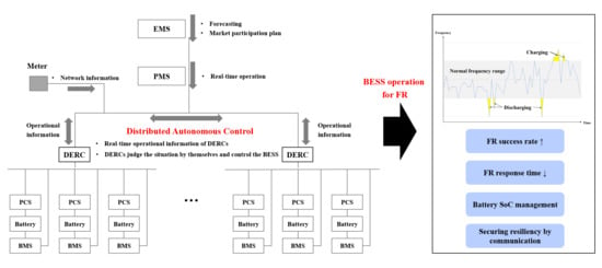
3.2. Scheme of Distributed Autonomous Control

Figure 7 shows the scheme of the central EMS for the generation of basic information necessary for the autonomous control of the DERC proposed in this study. Using the power exchange database, the price and hourly demand for FR are forecasted through a time-series analysis approach used in the demand forecasting technique. Based on the forecasted information, hourly bids in which the economic feasibility is maximized are determined for participation. When the bidding time is determined, a BESS operation plan is established in consideration of the power generation forecasting of renewable energy sources and the battery SoC of the BESS. According to the result of the bidding, EMS provides information necessary for operation to the DERC.
Figure 8a shows both the structure of the FR BESS and renewable energy sources in the structure based on the centralized control method, and Figure 8b shows the operation scheme of the DERC proposed in the present study. Currently, the FR BESS implemented in South Korea does not include renewable energy sources and the BESS is operated for the purposes of FR only. If renewable energy sources are applied in consideration of the economic feasibility and eco-friendliness, the following scheme will be in operation:
As shown in Figure 8a, the following are applied:
The EMS provides the PMS with various types of forecast information such as renewable generation, market price, and FR demand.
The meter provides the current system information such as real-time frequency, voltage, power input and output to the PMS.
The PMS checks the renewable generation output in real time and distributes a dedicated BESS; in addition, it separately operates the FR BESS, and each renewable energy source and FRC are charged/discharged following the PMS command.
To ensure economic feasibility, when renewable energy sources are interconnected, the PMS needs to monitor and manage more items, e.g., an additional BESS is required to stabilize the power output. However, when the DERC is applied, as shown in Figure 8b, various functions or permissions are assigned to it, which reduces the burden of the system operation, which may lead to an improved performance.
As shown in Figure 8b, we have the following:
The EMS provides the PMS with various types of forecast information such as renewable generation, market price, and FR demand.
The meter provides the current system information such as real-time frequency, voltage, and power input and output to the network so that the information is provided for both the PMS and DERC.
The PMS determines only the charge/discharge capacity based on the time slot for the entire system controlled according to the scheduled plan received from the EMS and sends the information to the DERC.
The DERC checks the real-time information from the meter and exchanges the information with each DERC according to the system status; in addition, it applies the control according to the input/out distribution and maximum utilization plan for the renewable energy sources.
As the DERC is operated in consideration of the economic feasibility, the priority is determined in consideration of the state of health (SoH) and SoC of the batteries, the cumulative consumption of the PCS, and the battery standby time. Unlike the existing operation method of an FR BESS, this method does not divide the demand capacity equally but determines the priority to increase the lifetime and improve the safety of the entire facility. The DERC determines the priorities through a mutual information exchange based on the following criteria:
y = w 1 x S o C + w 2 x P C S + w 3 x S o H + w 4 x t i m e
where
x S o C : battery SoC value (%). xSoC for discharging as is, and for charging, 100—xSoC is applied;
x P C S = 100 W T C C W P C S × 365 × n
  • W T C C : total cumulative consumption;
  • W P C S : PCS capacity;
  • n: lifetime provided by the manufacturer(year);
  • x S o H : battery SoH value [%]. xSoH is applied as indicated in the reference;
  • x t i m e : battery standby mode time rate [%]. x t i m e = H s t a n d b y 24 × 100 ;
  • Hstandby: battery standby mode time (if this value exceeds 24, it is 24); and
  • wn is the weight factor.
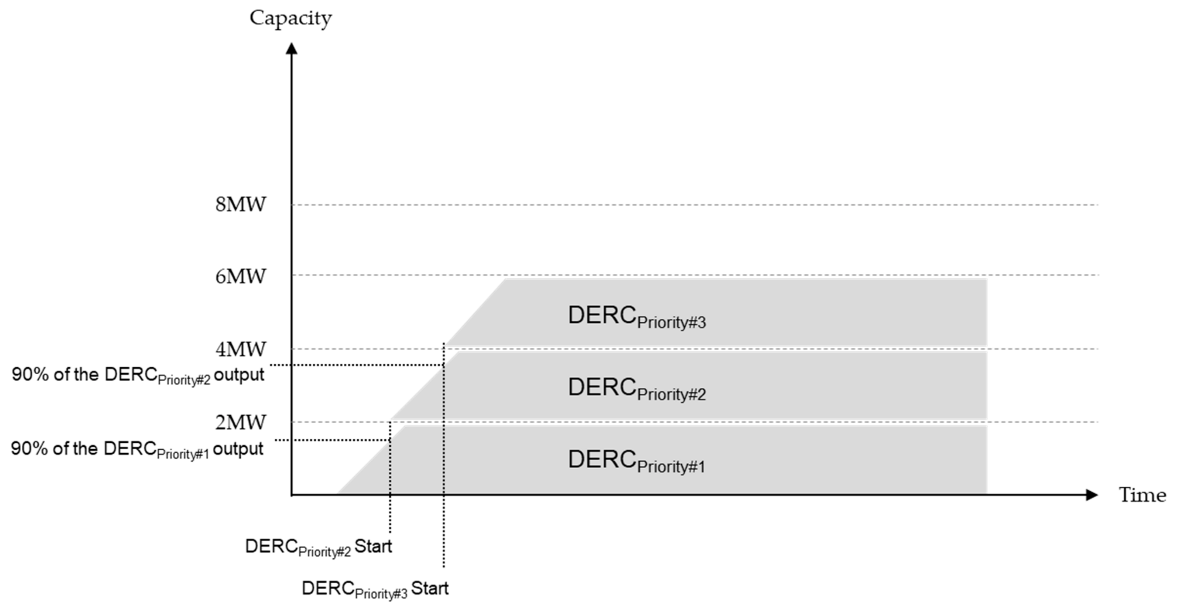
As described above, based on the status information of the BESSs controlled by each DERC, the priorities are predetermined according to the operating time and autonomous control is then applied. At this time, renewable generation based on the forecasted generation is considered as the generation source with significant output variation according to the demand capacity for FR, and autonomous control is conducted in the applicable DERC. Therefore, in the structure of the proposed control method, the PMS only checks the status information of the renewable energy sources through the DERC, and the DERC controls the integrated utilization of the energy resources.
Figure 9 shows the sequence for the charging or discharging of a total of 6000 kW, assuming that each DERC has 2000 kW of capacity. DERC priority 1 generates the power output at up to 2000 kW, and DERC priority 2 starts the output when DERC priority 1 reaches 90% of the output. In the same way, DERC priority 3 starts the power output when the output of DERC priority 2 reaches 90%. If the power output needs to be operated variably during the startup, DERC priority 3 is mainly used for a variable operation depending on the variable capacity, and DERC priorities 1 and 2 play a role in maintaining the appropriate output, including the output of the renewable energy sources, thereby ensuring stability over the battery lifetime and power output.
Figure 10 shows the scheme for starting and stopping each PCS because there are multiple PCSs in the DERC. The priority of each DERC is assigned from the PMS. Renewable generation output connected to the applicable DERC is received in real time. DERC selects the first PCS and starts the operation and assigns a flag because the PCS is in operation. If the PCS does not generate output for 60 s, the PCS is switched to standby mode. Otherwise, if the required output of the DERC is more than 90% of the last m-th PCS output, the next PCS is started. If the required output of the DERC is lower than the output of the PCS during operation, no additional start of the PCS is required. Otherwise, the SoC of the battery connected to the operating PCS is checked and as much continuous input or output as in the SoC is applied.
The scheme in Figure 10 is outlined as follows:
The new PCS continues to start operation until the capacity of the PCS currently running in the DERC is larger than the total DERC output.
The PCS in operation is operated until it can be operated while checking the battery SoC.
If the PCS does not generate output for 60 s owing to the change in the output of the renewable energy sources, the PCS is switched to standby mode.
Relevant status information is sent to the DERC in real time to maintain a real-time autonomous operation status.
For systems requiring a high performance, such as FR, the centralized control method collects a vast amount of information in the center and the command is delivered after a decision, which lead to an inevitable degradation of the performance. Therefore, with the adoption of the proposed system structure and scheme, with the advantages of a smaller BESS capacity and system operation environment, the cost-efficiency is expected to increase. In addition, unlike the existing method in which the same capacity is allocated to all PCSs of the BESS to accommodate the generation capacity demand for FR, with the proposed scheme, the system is operated by determining the priorities with factors considering the performance and lifetime of the system. In this way, the proposed scheme has an advantage in that it can be customized for various demands of the power exchange market.

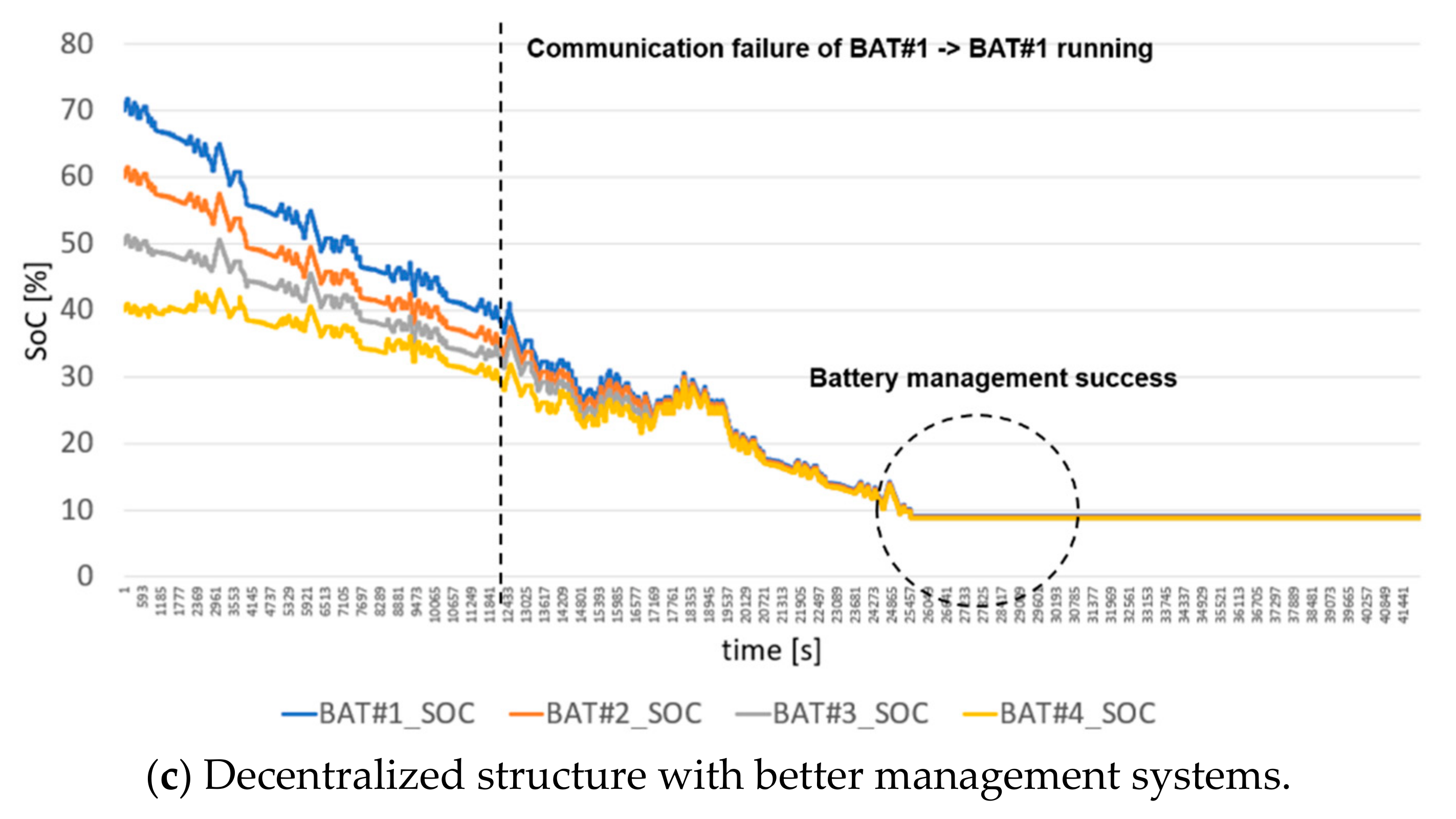
3.3. Scheme of Distributed Autonomous Control with Communication Failure

A single point of failure is one of the biggest concerns for the centralized control-based system. For instance, any existing device communication failure or malfunction of a controller during a normal operation process will lead to an abnormal operation. Therefore, resilient information exchange among local controllers is the key challenge of any control strategy. The proposed distributed autonomous control addresses the problem of communication failures for the FR BESS system. It can check the communication heartbeat and measurement to identify the problems when the expected outcome is not available from the BESS system. If there is any device-communication-failure problem at the DERC, the other DERCs will extend the control sections by choosing the nearest BESSs within the same system. Therefore, it can maintain a similar process time even though there is a failure during the frequency regulation process, assuming that we have the distributed autonomous control for FR BESS, as shown in Figure 10. If the PMS was not able to obtain the correct control response or measurements from BESS1, it will check the status of DERC1 and connected BESS1. Once the PMS identifies the problem of the system failure, it will execute the mitigation actions. For instance, if the communication link between DERC1 and BESS1 is failed, the PMS will send the switch over command to the DERC2. Then, DERC2 can control BESS1 so they can resume the normal FR BESS operations. These mitigation actions can be executed anytime whenever the PMS detects a system failure during the normal multiple PCS control scheme, as shown in Figure 10.

4. Case Study

4.1. Implemented System Configuration

To test and verify the performance of the distributed autonomous control-based FR BESS proposed in this study by comparing the structures shown in Figure 8a,b, the system used for the case study was configured in a laboratory, as shown in Figure 11. Figure 11 shows the DERC-based system configuration; however, for comparison with the existing FR ESS, all communications are connected to the same switching hub, and the centralized control method shown in Figure 8a based on the PMS was also configured to conduct tests in the same environment. For the system configuration, a 2 MW PCS consisting of 4 500 kW and four 1-MWh units, equivalent to a battery of 4 MWh in total, were used.

4.2. Time Performance Test by the Proposed Distibuted Autonomous Control

The most distinct advantage of the distributed structure is the improvement of the response speed. Accordingly, a test was conducted to confirm the improvement effect in the response speed compared to the existing centralized control system. In the case study environment, as shown in Figure 11, after selecting the points M1, M2, and M3 to measure signals and voltages, an oscilloscope was connected to these points, and the times T1 and T2 were measured, as shown in Figure 12. The time measurement for the response speed test started from the time when the frequency data generated in the simulator was received by the PMS, and the moment when the PCS responded and generated 98% of the rated output (490 kW) was set as the end time. The time measurement is divided into two sections, as shown in Figure 12, and each section is as follows:
  • T1: GFC calculation time and transmission time of PMS + output distribution calculation time of DERC.
  • T2: Time taken for command transmission from DERC to PCS + PCS response time.
For the time measurement for each section, the respective signals and voltage waveforms were measured using an oscilloscope, and the measurement points are as follows:
  • M1: Point of PMS receiving the frequency data of the simulator.
  • M2: Point of command transmission from DERC to PCS.
  • M3: PCS output point.
As a result of the response time test, the resulting waveforms, as shown in Figure 13, were acquired. The time for the T1 (M1–M2) section was measured at 97 ms, and the time for the T2 (M2–M3) section was 18 ms, making the total of 115 ms. The measurements were repeated in the same way, and it was confirmed that the average time of 116 ms was measured, confirming a time performance improvement of approximately 11%. Please note that centralized control took around a total of 129 ms.
The PMS calculates the control value of each battery in real time considering all the conditions of the system and controls the battery through the controller in the existing centralized structure. On the other hand, the controller controls the battery by checking only a part of the system status in the distributed structure. As a result, the proposed structure has fewer situations to consider and fewer communication targets, so it was possible to confirm the result of reducing the response time compared to the existing structure.
Due to the increased computational requirements for the controller, it requires more high-performance hardware specifications (the controller performs the function of the PMS in the proposed distributed structure) compared to the centralized control. Since this test was repeatedly tested using the same controllers and communication devices (i.e., same hardware specification), similar test results were obtained, as shown in Table 2.

4.3. Output Distribution Test by the Proposed Distributed Autonomous Control

The proposed distributed autonomous control can effectively manage the SoC of the battery by determining the operation priority when charging/discharging the battery. An output distribution test was conducted to identify the performance, and the test environment is as shown in Figure 11. In this case study, the results of the system with the FR algorithm in the existing centralized structure and the results of the system with the FR algorithm in the proposed distributed autonomous control structure were compared. SoC changes were recorded during 12 h of battery charge and discharge, and the initial SoCs of the four batteries were 70%, 60%, 50%, and 40%, respectively. The resulting waveform represents the SoC acquired from the PMS through the BMS.
Figure 14a shows the FR BESS with centralized control structure. In the case when the centralized controller was overloaded due to too many requests (i.e., stress testing), it failed to discharge the battery as it was designed. For instance, it was designed to converge at 10% SoC. However, the BESS1 was discharged below 1% of SoC. A communication failure test was executed to identify the impact of the physical system, as described in Figure 14b. In this scenario, the communication link between DERC1 and BESS1 was disconnected at the predefined time. Once the communication was disconnected, DERC1 lost its control capability of BESS1, and the PMS was not able to obtain any status and measurements from BESS1. In a similar way, (1) the stress test and (2) the communication failure test were conducted for the proposed distributed autonomous control structure for FR BESS, as illustrated in Figure 14c. In this scenario, the distributed autonomous controllers managed the larger number of requests and performed a stable FR performance with the same capacity. Furthermore, it can detect the communication failure between DERC1 and BESS1 within 10 ms. After detecting the fault, the proposed distributed autonomous control implemented on the PMS enabled the backup communication links from DERC1 to BESS1. Therefore, all systems went back to the normal operations within 25 ms time windows.

5. Conclusions

For the reliable operation of the transmission system, a stable FR performance is necessary by matching the supply and demand. Existing synchronous generators using a rotating machine use inertial energy, taking some time for changing the supply according to changes in demand, and for this reason, 100% of the output of the generator is not always used. Therefore, in South Korea, 376 MW FR BESSs are installed and are in operation at 13 different sites.
An FR BESS operation currently adopts a centralized control method, and in this study, a novel method is proposed to improve the FR performance by introducing a distributed autonomous control system. In the proposed FR BESS, with only the information necessary from the central PMS, the DERC achieves autonomous control of the FR BESS with direct measurement information in the local and status information of the adjacent DERCs.
With the proposed scheme, an improvement of the frequency control speed of approximately 11% or higher was confirmed compared to an FRC-based FR BESS, and it was also demonstrated that through the fast frequency response of the proposed scheme, the battery energy used for FR can be reduced. In addition, unlike a BESS that is disconnected owing to an insufficient SoC, with the adoption of a centralized control method, the BESS is not disconnected with a remaining SoC of approximately 9% when applying the newly proposed distributed autonomous control method. Therefore, the BESS for FR based on the proposed distributed autonomous control method is expected to contribute to more stable and improved results with less investment costs.
The role of Korea power exchange (KPX) is to plan the supply of electricity to the whole of Korea, and the role of the Korean utility (KEPCO) is to operate the power system. Since a private company cannot legally operate ESS for FR, case studies were verified through factory acceptance test (FAT) instead of real systems. Therefore, we are planning a national project proposal to apply the proposed method to real systems.
In the future work, the BESS for FR based on the proposed distributed autonomous control method is expected to contribute to more stable and improved results with less in-vestment costs. In addition, if the characteristics of the distributed structure proposed in this paper and artificial intelligence (AI) are combined, the BESS can be operated not only for FR, but also for peak shaving, the smoothing of renewable energy output, and load leveling by using a few batteries. As a result, the efficiency of BESS can be improved.

Author Contributions

Conceptualization, J.H. and H.-S.K.; methodology, J.H.; software, H.-S.K.; validation, H.-S.K. and I.-S.C.; formal analysis, I.-S.C.; investigation, H.-S.K.; resources, J.H.; data curation, H.-S.K.; writing—original draft preparation, J.H.; writing—review and editing, J.H.; visualization, H.-S.K.; supervision, I.-S.C.; project administration, I.-S.C.; funding acquisition, I.-S.C. All authors have read and agreed to the published version of the manuscript.

Funding

This work was supported by the Korea Institute of Energy Technology Evaluation and Planning (KETEP) and the Ministry of Trade, Industry and Energy (MOTIE) of the Republic of Korea (No. 20194310100060).

Institutional Review Board Statement

Not applicable.

Informed Consent Statement

Not applicable.

Data Availability Statement

The data presented in this study are available on request from the corresponding author.

Conflicts of Interest

The authors declare no conflict of interest.

References

  1. Makholm, J.D. The New “Three Ds” in Regulation—Decarbonization, Decentralization, and Digitization. Nat. Gas Electr. 2018, 35, 18–22. [Google Scholar] [CrossRef]
  2. Al-Gabalawy, M.; Mahmoud, K.; Darwish, M.M.F.; Dawson, J.A.; Lehtonen, M.; Hosny, N.S. Reliable and Robust Observer for Simultaneously Estimating State-of-Charge and State-of-Health of LiFePO4 Batteries. Appl. Sci. 2021, 11, 3609. [Google Scholar] [CrossRef]
  3. Bendary, A.F.; Abdelaziz, A.Y.; Ismail, M.M.; Mahmoud, K.; Lehtonen, M.; Darwish, M.M.F. Proposed ANFIS Based Approach for Fault Tracking, Detection, Clearing and Rearrangement for Photovoltaic System. Sensors 2021, 21, 2269. [Google Scholar] [CrossRef]
  4. Abaza, A.; El-Sehiemy, R.A.; Mahmoud, K.; Lehtonen, M.; Darwish, M.M.F. Optimal Estimation of Proton Exchange Membrane Fuel Cells Parameter Based on Coyote Optimization Algorithm. Appl. Sci. 2021, 11, 2052. [Google Scholar] [CrossRef]
  5. Schimpe, M.; Piesch, C.; Hesse, H.C.; Paß, J.; Ritter, S.; Jossen, A. Power Flow Distribution Strategy for Improved Power Electronics Energy Efficiency in Battery Storage Systems: Development and Implementation in a Utility-Scale System. Energies 2018, 11, 533. [Google Scholar] [CrossRef] [Green Version]
  6. Eyer, J.; Corey, G. Energy Storage for the Electricity Grid: Benefits and Market Potential Assessment Guidel. Sandia Natl. Lab. SAND2010-0815 2010, 20, 5. [Google Scholar]
  7. Lim, G.-P.; Han, H.-G.; Chang, B.-H.; Yang, S.-K.; Yoon, Y.-B. Demonstration to Operate and Control Frequency Regulation of Power System by 4MW Energy Storage System. Trans. Korean Inst. Electr. Eng. 2014, 63, 169–177. [Google Scholar] [CrossRef] [Green Version]
  8. Lim, G.-P.; Choi, Y.-H.; Im, J.-H. Development of Operation and Control Technology of Energy Storage System for Frequency Regulation and Operation by Grid Connected Automatic Control. Trans. Korean Inst. Electr. Eng. 2016, 65, 235–241. [Google Scholar] [CrossRef]
  9. Dang, J.; Seuss, J.; Suneja, L.; Harley, R.G. SoC Feedback Control for Wind and ESS Hybrid Power System Frequency Regulation. IEEE J. Emerg. Sel. Topics Power Electron. 2014, 2, 79–86. [Google Scholar] [CrossRef]
  10. Mercier, P.; Cherkaoui, R.; Oudalov, A. Optimizing a Battery Energy Storage System for Frequency Control Application in an Isolated Power System. IEEE Trans. Power Syst. 2009, 24, 1469–1477. [Google Scholar] [CrossRef]
  11. Kwon, S.-J.; Kim, G.; Park, J.; Lim, J.-H.; Choi, J.; Kim, J. Research of Adaptive Extended Kalman Filter-Based SOC Estimator for Frequency Regulation ESS. Appl. Sci. 2019, 9, 4274. [Google Scholar] [CrossRef] [Green Version]
  12. Yang, J.-S.; Choi, J.-Y.; An, G.-H.; Choi, Y.-J.; Kim, M.-H.; Won, D.-J. Optimal Scheduling and Real-Time State-of-Charge Management of Energy Storage System for Frequency Regulation. Energies 2016, 9, 1010. [Google Scholar] [CrossRef]
  13. Wang, Y.; Xu, Y.; Tang, Y.; Liao, K.; Syed, M.H.; Guillo-Sansano, E.; Burt, G.M. Aggregated Energy Storage for Power System Frequency Control: A Finite-Time Consensus Approach. IEEE Trans. Smart Grid 2018, 10, 3675–3686. [Google Scholar] [CrossRef] [Green Version]
  14. Ly, A.; Bashash, S. Fast Transactive Control for Frequency Regulation in Smart Grids with Demand Response and Energy Storage. Energies 2020, 13, 4771. [Google Scholar] [CrossRef]
  15. Cho, S.-M.; Kim, J.-S.; Kim, J.-C. Optimal Operation Parameter Estimation of Energy Storage for Frequency Regulation. Energies 2019, 12, 1782. [Google Scholar] [CrossRef] [Green Version]
  16. Yoon, M.; Lee, J.; Song, S.; Yoo, Y.; Jang, G.; Jung, S.; Hwang, S. Utilization of Energy Storage System for Frequency Regulation in Large-Scale Transmission System. Energies 2019, 12, 3898. [Google Scholar] [CrossRef] [Green Version]
  17. Lin, H.; Jin, J.; Lin, Q.; Li, B.; Wei, C.; Kang, W.; Chen, M. Distributed Settlement of Frequency Regulation Based on a Battery Energy Storage System. Energies 2019, 12, 199. [Google Scholar] [CrossRef] [Green Version]
  18. Benato, R.; Dambone Sessa, S.; Musio, M.; Palone, F.; Polito, R.M. Italian Experience on Electrical Storage Ageing for Primary Frequency Regulation. Energies 2018, 11, 2087. [Google Scholar] [CrossRef] [Green Version]
  19. Cho, S.-M.; Yun, S.-Y. Optimal Power Assignment of Energy Storage Systems to Improve the Energy Storage Efficiency for Frequency Regulation. Energies 2017, 10, 2092. [Google Scholar] [CrossRef] [Green Version]
  20. Lee, E.; Kim, J. Assessing the Benefits of Battery Energy Storage Systems for Frequency Regulation, Based on Electricity Market Price Forecasting. Appl. Sci. 2019, 9, 2147. [Google Scholar] [CrossRef] [Green Version]
  21. Andrenacci, N.; Chiodo, E.; Lauria, D.; Mottola, F. Life Cycle Estimation of Battery Energy Storage Systems for Primary Frequency Regulation. Energies 2018, 11, 3320. [Google Scholar] [CrossRef] [Green Version]
  22. Delille, G.; François, B.; Malarange, G. Dynamic frequency control support: A virtual inertia provided by distributed energy storage to isolated power systems. In Proceedings of the 2010 IEEE PES Innovative Smart Grid Technologies Conference Europe (ISGT Europe), Gothenburg, Sweden, 11–13 October 2010. [Google Scholar]
Figure 1. Example of increasing generation capacity by employing BESS for FR [7,8].
Energies 14 02672 g001
Figure 2. FR BESS locations in South Korea [8,22].
Energies 14 02672 g002
Figure 3. Existing configuration of the BESS for frequency regulation [7,8].
Energies 14 02672 g003
Figure 4. Concept of the frequency regulation scheme.
Energies 14 02672 g004
Figure 5. Proposed system configuration used to consider commercial FR market participation with a BESS and renewables.
Energies 14 02672 g005
Figure 6. Flowchart of the proposed method.
Energies 14 02672 g006
Figure 7. Determination of the bidding in FR market using EMS.
Energies 14 02672 g007
Figure 8. (a) Centralization control scheme and (b) DERC-based distributed autonomous control scheme of renewable generation and BESS for frequency regulation.
Energies 14 02672 g008
Figure 9. 6 MW charging/discharging operation scheme based on DERC priority.
Energies 14 02672 g009
Figure 10. The flowchart for the multiple PCS control scheme of a DERC (charging case).
Energies 14 02672 g010
Figure 11. System configuration used for case study.
Energies 14 02672 g011
Figure 12. Time performance test method.
Energies 14 02672 g012
Figure 13. Results of time performance test for verification of the proposed system.
Energies 14 02672 g013
Figure 14. SoC of battery operation under centralized and decentralized structures.
Energies 14 02672 g014aEnergies 14 02672 g014b
Table 1. Status of the frequency operation of the transmission system in South Korea [7,8].
Frequency
(Hz)
Less than 59.859.81–59.959.91–59.9559.96–60.060.01–60.0560.06–60.160.11–60.2More than 60.2
Number of cases0
(0%)
26
(0%)
3730
(0.28%)
635,699
(51.2%)
644,055
(48.09%)
5690
(0.42%)
00
Table 2. Results of the test (time performance).
Number of Tests12345678
response time (ms)
(centralized structure)
131130128129131128130129
Response time (ms)
(distributed structure)
115118117115116118115115
Publisher’s Note: MDPI stays neutral with regard to jurisdictional claims in published maps and institutional affiliations.

