Article

Investigative Study of Vertical Electrodes Encased in Concrete/Mortar with Various Sizes of Air Voids

by
Hanis Hamizah Hizamul-Din
1,
Normiza Mohamad Nor
1,*,
Dzulkafley Abd Samad
2 and
Muhd Norhasri Muhd Sidek
3
1
Faculty of Engineering, Multimedia University, Jalan Multimedia, Cyberjaya 63100, Malaysia
2
AKS Perunding Sdn. Bhd, 90B, Jalan Burhanuddin Helmi, Taman Tun Dr Ismail, Kuala Lumpur 60000, Malaysia
3
Faculty of Civil Engineering, Universiti Teknologi MARA, Shah Alam, Selangor 40450, Malaysia
*
Author to whom correspondence should be addressed.
Energies 2021, 14(9), 2659; https://doi.org/10.3390/en14092659
Submission received: 17 March 2021 / Revised: 22 April 2021 / Accepted: 28 April 2021 / Published: 6 May 2021
(This article belongs to the Section F: Electrical Engineering)

Abstract

:
Ionisation can occur in the soil when high impulse currents are subjected to grounding systems. This occurrence is generated by a difference in the dielectric strength value between the soil and air voids. Several published works investigating the ionisation process in soil have seen that the degree of ionisation is dependent on several factors, among them soil resistivity, ground electrode size and impulse polarity. The effects on soil resistivity, such as the moisture content in soil, soil grain size, type of soil and its temperature, have been studied; however, the effect of the size of air voids in soil has not been extensively presented. This study considered four rod electrodes—a conventional rod electrode, conventional electrode with porous concrete (PC), conventional electrode with concrete mixed with a foaming agent (FC) and conventional electrode with concrete (NC)—to provide variations in the size of air voids. Resistance values, RDC, were measured for all these electrodes, and we found that the conventional rod electrode had the lowest value. A detailed evaluation of these rod electrodes under high impulse conditions revealed that similar current rise and discharge times were seen in all electrodes; however, PC, with the largest size of air voids, had the lowest impulse impedance (Zimp value) for the current magnitudes below 2 kA.

1. Introduction

A vertical rod electrode is normally driven to the required depth, horizontally or vertically extended, in plurality to other electrodes, to achieve a low resistance value. It is a general concept that if a vertical rod electrode penetrates to a deeper level, where the soil resistivity is low, the grounding system becomes more effective in discharging high currents into the ground. Many studies on vertical rod electrodes also been conducted under high impulse conditions [1,2,3,4], showing a reduction in impulse impedance (Zimp values) from its steady-state resistance value, RDC. It was also observed in [1] that a single rod (high RDC) had a higher ratio of Zimp to RDC than multiple rods (low RDC), indicating a large reduction in Zimp from its RDC values. Similar findings were observed by Vainer [3], who found that under high currents, a smaller resistance reduction occurred for earth electrodes of a low AC ground resistance, in comparison to those of a high AC earth resistance value. This indicates that the degree of non-linearity is dependent on the AC or DC ground resistance values.
Other interesting studies [5,6] have also seen a relationship between the degree of non-linearity in soil and other parameters, such as impulse polarity, current magnitudes and soil resistivity. There have also been studies on the effect of soil grain size on the characteristics of soil [7,8]. Cabrera et al. [7] have found that sand with high resistivity experienced a higher breakdown voltage than sand with smaller particles. This was dissimilar to that found by Mohamad Nor et al. [8], where for the same percentage of water content, medium grain size sand had a lower critical electric field, Ec, than that of fine grain size sand. Despite extensive studies on the effect of soil resistivity on impulse characteristics under high impulse conditions, knowledge about the effects of air voids on the soil characteristics under high impulse conditions is still limited.
This paper is directed towards differentiating the air voids in the soil, with the rod electrodes encased in concrete and mortar with various sizes of air gaps, and investigating the effects of these electrodes at low voltage and high impulse currents. Concrete and mortar encased electrodes were used in this study as a means of controlling the air voids in the test sample. Studies on rod electrodes encased in concrete [9,10] and bentonite [9,11] under high impulse conditions were presented in previously published work. Rodrigues et al. [9] performed a comparative study among three electrodes: conventional rod, concrete- and bentonite-encased rod electrodes. A large percentage difference in measured impulse impedance values was only seen at a lower range of impulse voltage levels, below 25 kV. Furthermore, a similar impulse impedance value was seen for all three electrodes at higher voltage levels. They observed that at higher voltage levels, 60 kV, producing current magnitudes of approximately 9 kA, high oscillations occurred in the current trace, which was due to a fracture in the concrete. Dick and Holliday [10] also observed a fracture in a concrete-encased electrode when high-magnitude, short duration alternating current tests were performed. On the other hand, no oscillation on the current trace nor fracture in the bentonite-encased rod electrode was reported in [11].
Despite much work that has been carried out on concrete or conductive material encased rod electrodes, helping to reduce the resistance values, no study has considered air voids in concrete or other materials used in grounding systems. It was observed in [8] that for drier soil, a larger percent reduction in Zimp was found compared to soil with a higher percentage of water content. Further, in [12] it was presented that medium grain size sand had a lower ionisation voltage and lower resistance values than those of fine grain size sand, when both test media were subjected to high impulse conditions. As generally known, medium grain size sand is expected to have larger air voids than fine grain size sand. Thus, this can be the reason why the medium grain size sand (larger air voids) initiated an ionisation process at a lower voltage and showed lower impulse impedance values than the fine grain sand (smaller air voids), as seen in [12]. Based on the evidence that air void sizes in soil become an important parameter in affecting the characteristics of soil under fast transients, this paper presents experimental and simulated results about rod electrodes encased in concrete and mortar with various sizes of air voids. Since the experiments are field tests, it is difficult to control the size of air voids in the soil at site; thus, concrete and mortar with variations in air voids were used to encase/cast the rod electrode. Since concrete or other hard materials were also applied in studies mentioned earlier [9,11] and used in grounding installations, rod electrodes encased in concrete and mortar can be considered in this present study to investigate the effect of air voids on soil characteristics under high impulse conditions.

2. Test System

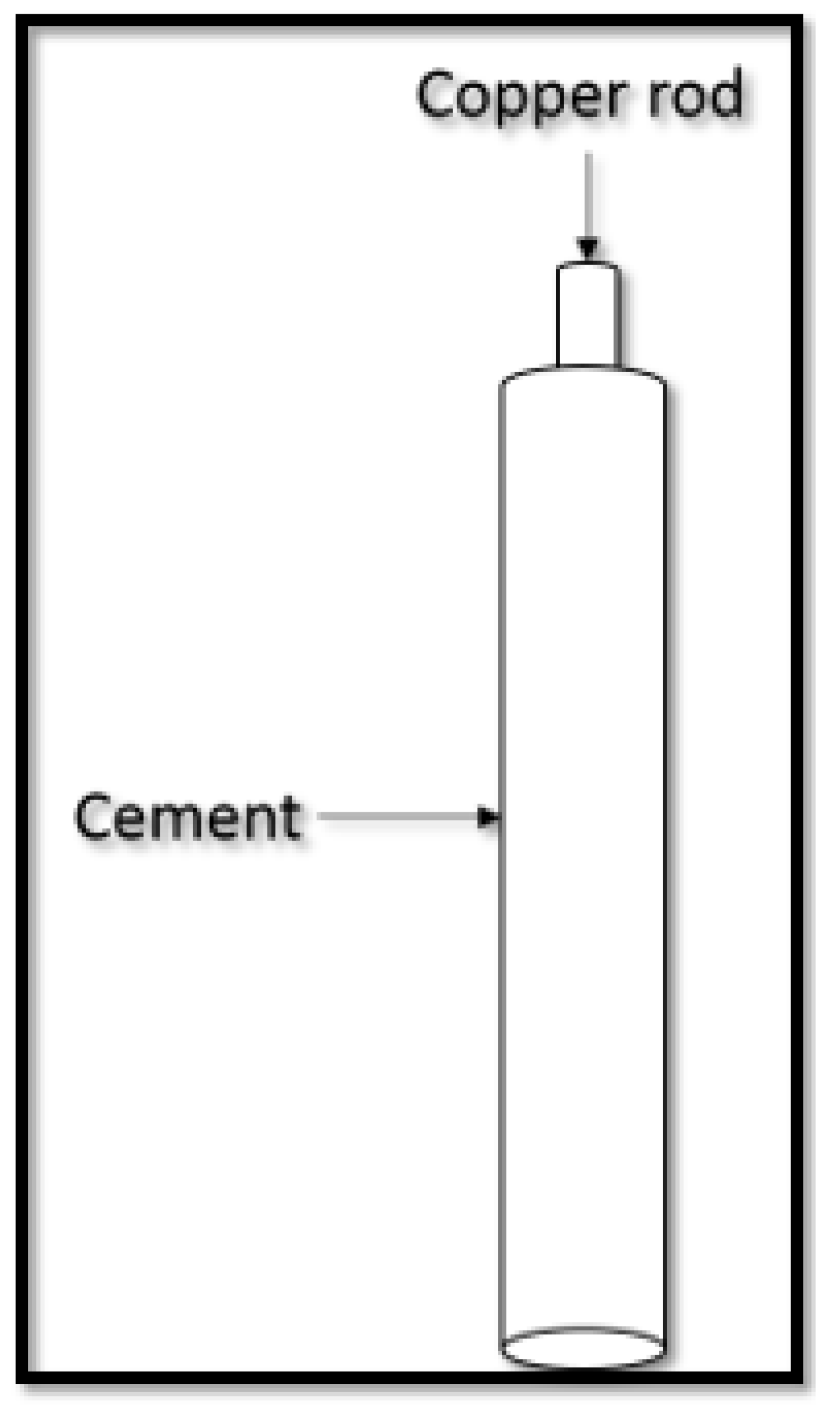
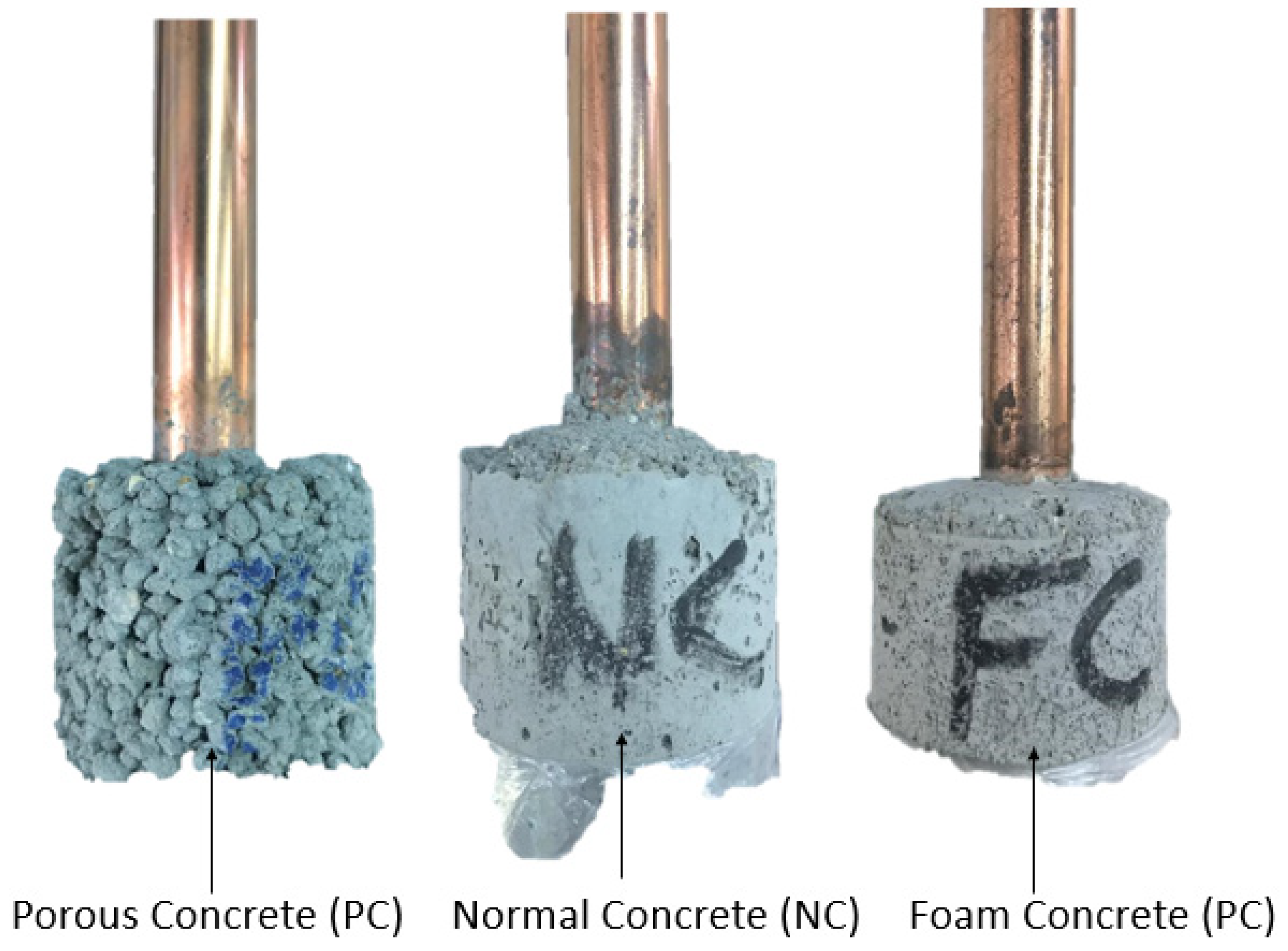
2.1. Ground Rod Electrodes under Tests

Four tested ground rod electrodes were used during the course of this study: conventional electrode (CE), conventional electrode encased in mortar with foaming agent (FC), conventional electrode encased in porous concrete (PC) and conventional electrode encased in mortar (NC). Coarse aggregates were used, ranging from sand to stone; coarser aggregates were mostly used for PC, while sand of smaller aggregate size was used for mortar (NC). The conventional rod electrode, which was also encased along with FC, PC and NC, was 1.5 m in length, 16 mm in diameter, and 1 m of the conventional electrode was covered with these materials. In the course of the FC, PC and NC preparation, a PVC tube with a diameter of 40 mm was used, where the conventional rod was placed in the middle of the PVC tube, and these materials were poured into the PVC tube, as shown in Figure 1. Different materials were used to create various voids in the mixtures. For FC, sand with grain size of less than 2 mm, ordinary Portland cement, water and a foaming agent were used. Furthermore, sand with grain size of 2 to 5 mm, ordinary Portland cement and water were used for PC, whilst sand with the grain size of less than 5 mm, ordinary Portland cement and water were used for NC. The composition of the materials used to make FC, PC and NC is summarized in Table 1. As can be seen in the table, aggregates were only used for PC, to create more air voids in the soil. The foaming agent used in this research was synthetic-based, namely Meyco SLF 30, and it was packed in a 20 L container. The foam was formulated to produce air bubbles able to resist the physical and chemical forces imposed on them during mixing, placing and hardening of concrete and mortar. In this work, all of these mixtures were of various ratios, mainly to provide various sizes of air voids. The materials were mixed in a mixer, then poured into the PVC tube, and after 24 h of casting, PC and NC were demoulded from the PVC mould. The FC samples were demoulded after 48 h, and the formed work went into the hydration process. Concrete, mortar and mortar with foaming agent encased the rod electrode. The mixtures were also formed into three blocks, each having the size of 30 cm x 30 cm x 30 cm, to measure their densities. Table 2 shows the density of each block, and, as expected, NC had the highest density due to its compacted soil; FC had the lowest density due to the void creation by the foaming agent. Though in the finished product (Figure 2), PC had larger air gaps, as seen in Figure 3, FC had a lower density due to the smaller amount of sand used, while a foaming agent, or lighter weight, was used to fill up the volume of the mixture. The compressive strengths of FC, PC and NC are presented in Table 3, for all the blocks, as the number of days increased. The specimens were cured for 3, 7 and 28 days. The method of curing was according to BS EN 12390-2:2009 [13]. Expectedly, the compressive strength gradually increased towards its characteristic strength of 28 days for all the blocks, and NC (with the smallest size of air voids) had the best compressive strength since it was made from mortar. It is clearly seen in the table that FC had the lowest compressive strength, which is due to the use of the foaming agent to create the air voids in the blocks. As seen in Table 2, the lowest-density block was in FC, due to the presence of the air voids; hence, low compressive strength was expectedly seen in FC.
Similarly, the porosities of FC, PC and NC were quantified and found to be 21.69%, 18.81% and 21.2%, respectively. The low porosity in the PC could again be related to the large sizes of air gaps, in comparison to mortar (NC) and mortar with foaming agent (FC). The large sizes of air gaps in PC could also have caused low water absorption in PC, where it was 9.67%, in comparison to NC and FC with 10.27% and 14.73%, respectively.
The structure of the air void system of FC, PC and NC was scanned using scanning electron microscopy (SEM). It was found that PC had the biggest sizes of air voids—a majority of them reaching more than 0.5 mm—followed by FC and NC. Photos of these structures of the air void systems in PC, FC and NC can be seen in Figure 3, Figure 4 and Figure 5.
All of these electrodes were installed within the same areas at a field site, 20 m apart from one another. As mentioned in [2], there are differences in soil resistivity profiles, even for distances of 10 m apart. In this study, various sites were identified and four conventional electrodes were installed there at 20 m from each other. The RDC values were measured by the Fall-of-Potential (FoP) method for all of these four conventional electrodes, and the difference between the RDC values was intended to be kept within a 20% limit, so that the variation in the results would be affected only by differences in the tested electrodes and not by differences in the soil resistivity or local soil conditions. After several attempts at several available sites, we observed that it was difficult to achieve the 20% variation difference of RDC from one electrode to another due to the heterogeneity in the soil resistivity at places 20 m apart from each other, as highlighted in [2], whereby just a 10 m variation in soil resistivity was observed. A site was then identified where the variation in RDC values for these conventional electrodes was approximately 30%. There, the resistance values were 67, 102, 80 and 82 Ω for the conventional rod electrodes 1, 2, 3 and 4, respectively.
During installation, the conventional rod electrodes were hammered to the depth of 1.5 m. The conventional electrodes 2, 3 and 4 were removed and replaced with tested concreted and mortared electrodes FC, PC and NC, respectively. Concerned that the concrete and mortar might break during the hammering of the electrodes into the ground, for each of them, we dug a hole in the ground of approximately 5 cm in diameter, to the depth of 1.5 m, with the help of an auger. The concreted and mortared electrodes were then slowly lowered to the ground, and the RDC values were then measured by the FoP method. It was found that the tested rod electrodes were 67, 2290.9, 732.3 and 594.5 Ω, respectively, for conventional rod electrode, FC, PC and NC. Furthermore, the RDC values of FC, PC and NC were 96%, 89% and 86%, respectively, of the RDC of the conventional electrodes that had been installed earlier. The expectation was that the RDC of a conventional rod electrode would be low, due to direct contact between the electrode and natural soil. It was inferred that FC having the highest RDC could have been due to the presence of the foaming agent in its mixture, which gave it a high resistance value. Due to the specific interest of this study, which was the effect of the size of the air gaps, it would have been beyond the scope of the paper to study the properties of the foaming agent at this stage. Higher RDC in PC in comparison to NC could have been caused by bigger air voids in PC; thus, having large resistance in the air gaps meaned less conduction in air voids. This is similar to the conditions in rocks, granite, gravel and sand, as reported in [14], where less water and minerals were trapped in this kind of soil media, exhibiting high soil resistivity and resistance values.

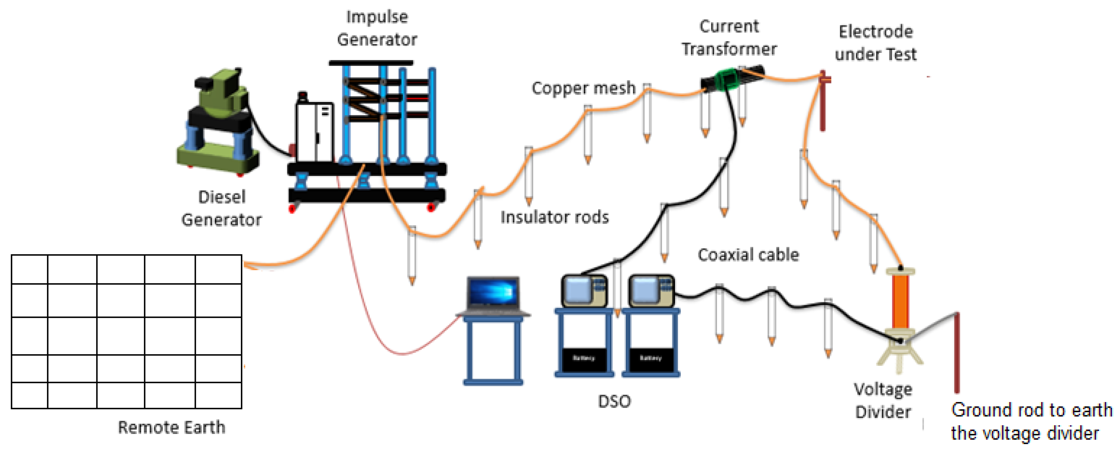
2.2. Impulse Test Arrangement

An impulse generator generating up to 300 kV, 10 kA was used to carry out this test, whereby impulse voltage was measured with a resistive divider, and impulse current was measured with a current transformer. In addition, the voltage and current readings were obtained with the use of digital storage oscilloscopes. Furthermore, a ground return electrode of 30 × 50 m was used, and with the FoP method the measured RDC was found to be 8 Ω. Figure 6 shows the impulse test arrangement used in the study for each test electrode.

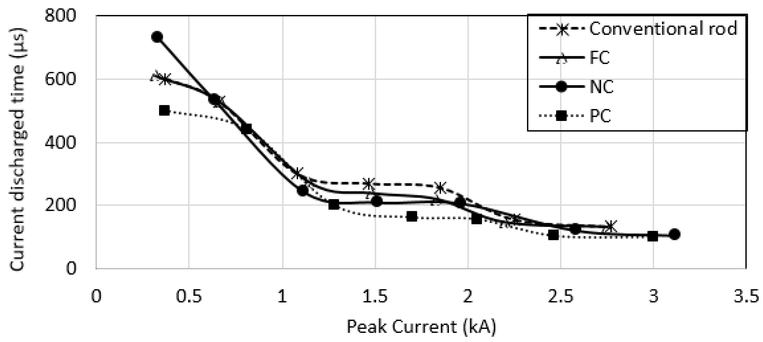
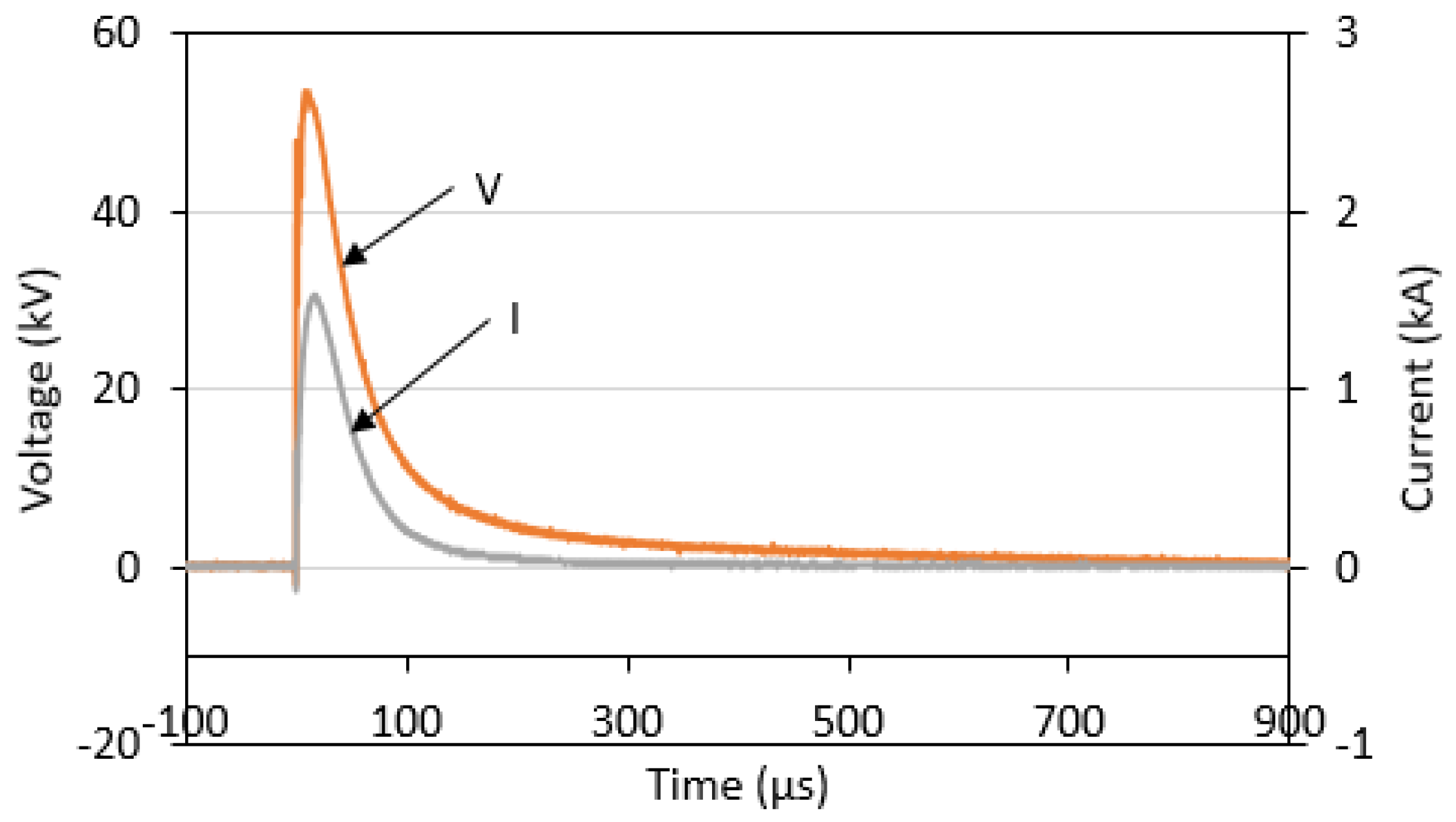
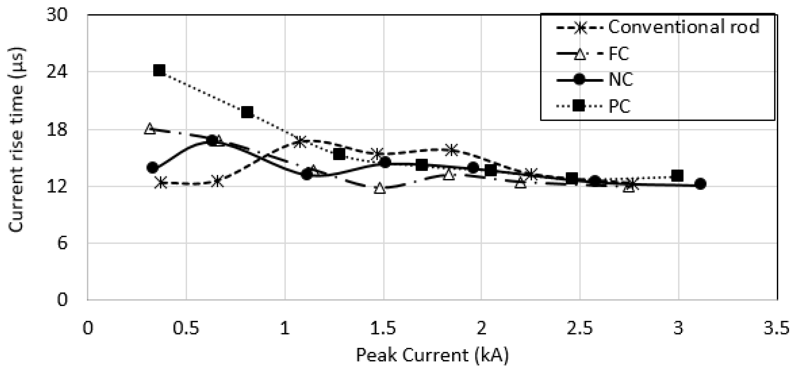
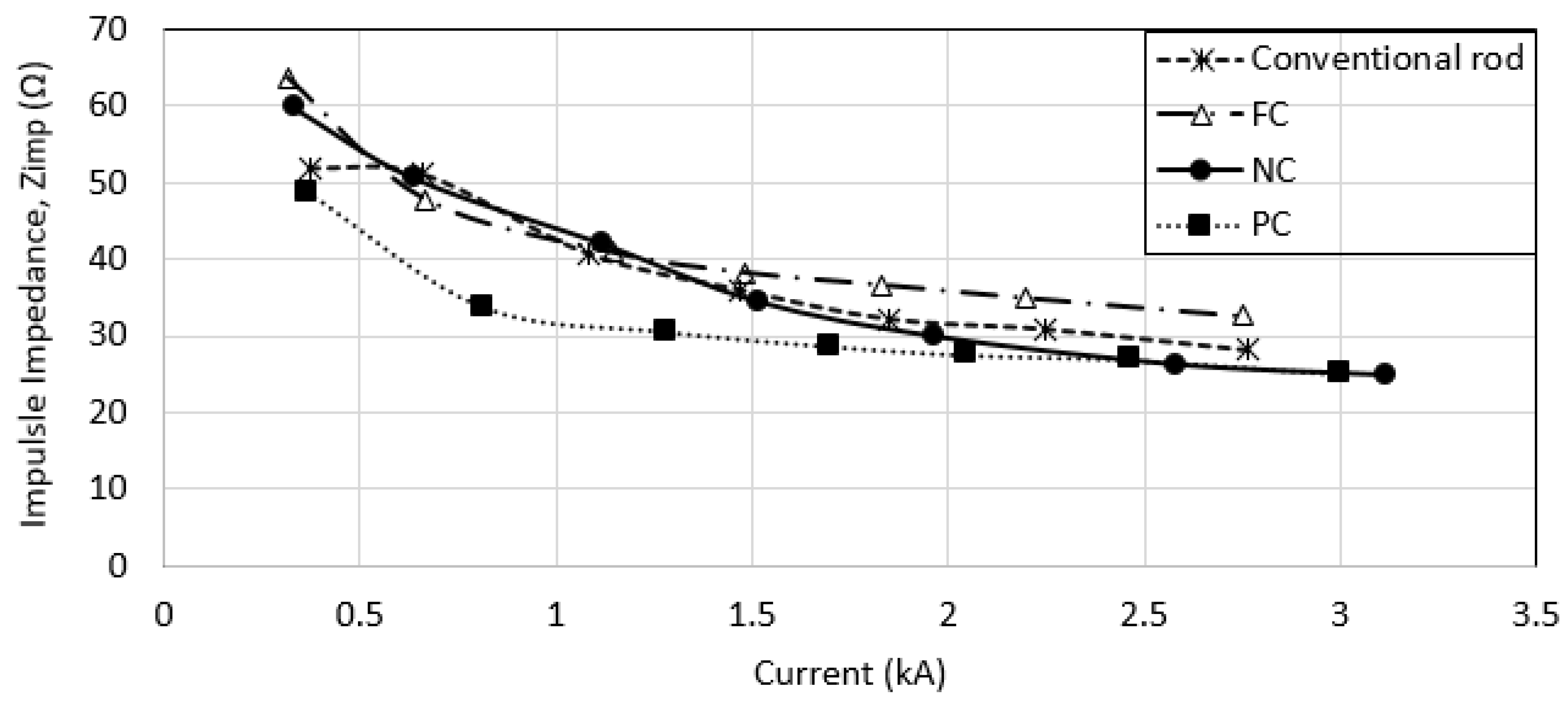
3. Impulse Test Results

Test electrodes were subjected to increasing charging voltage, from 30 to 210 kV. Voltage and current traces at a charging voltage of 100 kV for NC are shown in Figure 7. At different levels of charging voltage, the voltage and current showed similar traces to those in Figure 7; i.e., both voltage and current traces had fast rise times and slow discharge times. Current traces were found to rise and discharge approximately at the same time as the voltage traces, for all electrodes at different levels of voltage, indicating that the tested electrodes had a predominantly resistive behaviour. These rise and current discharged times for all electrodes were plotted, as shown in Figure 8 and Figure 9, respectively. Figure 8 reflects the fastest current rise time in the conventional electrode, and the slowest current rise time in PC, for the current magnitudes of below 2 kA. In [8] and [15], the current rise time was defined as the propagation rate of the ionisation process, of which they [8,15] observed that at low current magnitudes, a slower peak current was observed, and current rise times occurred faster as the current magnitudes increased. In this study, slow current rise times were observed for PC and FC at current magnitudes of below 2 kA, with the difference of above 40% of the conventional electrode, possibly caused by large air voids in PC and FC, thus taking a longer rate of conduction growth in comparison to the conventional electrodes. As the current magnitudes were increased, these air voids in PC and FC might have experienced a similar rate of conduction growth as in a conventional electrode.
Another notable observation from these impulse tests was the discharge time; a clear dependency of the current discharge time on its current magnitudes was observed, where the higher the current magnitude, the faster the discharge times were (see Figure 9). This again could have been caused by a faster conduction current growth as the current magnitudes increased. Having said that, however, little dependency of these current discharge times on the size of air voids in these concreted and mortared electrodes was observed.
From impulse voltage and current traces, impulse impedance (Zimp) values, calculated as peak voltage divided by peak current, which are plotted in Figure 10, show that Zimp decreased with increasing current magnitudes. A notable remark derived from this figure is that PC (with the largest air voids) had the smallest Zimp values for the current magnitudes of below 2.5 kA, while other electrodes had similar Zimp values for all current levels, which indicated that better conduction could be achieved in larger air voids of soil media. At current levels of more than 2.5 kA, Zimp values of PC were found to be close to Zimp of the other electrodes, which could have been caused by the presence of more current paths at higher current magnitudes; thus, the conduction growth occurred at a similar rate for all electrodes and independently of the size of the air voids. A similar observable effect was seen in [9], where at lower voltage magnitudes, variation in Zimp was seen in concrete, bentonite and conventional electrodes; however, as the voltage magnitudes increased, similar Zimp values were observed. It has been highlighted in this study that despite the large difference in RDC between the conventional and the concreted and mortared electrodes, as presented in Section 2.1, a small difference was seen in their impulse characteristics, including current rise times, current discharged times and impulse impedance values. This study also showed that the large air voids in concrete, which were found in PC, could have significantly helped to lower the Zimp, and this is a potential consideration for the future design of grounding systems.

4. Conclusions

Investigations of soil ionisation were carried out on four rod electrodes: conventional rod electrode, conventional rod electrode encased with porous concrete (PC), conventional rod electrode encased with concrete mixed with foaming agent (FC) and conventional rod electrode encased with concrete (NC). The study was performed with a general assumption that air voids could be one of the main factors contributing to ionisation in soil, given that ionisation occurs due to dielectric difference between the soil and the air void. The electrodes were encased with concrete, mortar or mortar with foaming agent with a variety of air voids formed. With the help of scanning electron microscopy (SEM), we observed that the PC had the largest size of air voids, followed by FC and NC. When all of these electrodes were installed at the field sites, we found that FC had the highest RDC, more than 2000 Ω, followed by PC, NC and the conventional rod electrode, which we think was caused by a large resistance in the air voids. Furthermore, impulse test results revealed that PC and FC demonstrated a slow peak current, indicating a slow growth of conduction in air voids at current magnitudes of below 2.5 kA. In addition, impulse impedance, Zimp on the other hand, was found to be the lowest in PC (with the largest air voids), indicating that air voids had a significant role in reducing the Zimp.

Author Contributions

H.H.H.-D. and N.M.N. were involved in setting up the experiment, D.A.S. and M.N.M.S. helped with the design and materials preparation, H.H.H.-D. and N.M.N. sorted out the data, H.H.H.-D. prepared the draft and N.M.N. helped with validation of analyses. All authors have read and agreed to the published version of the manuscript.

Funding

This research was funded by Telekom Malaysia Research and Development (TMR&D), grant number MMUE190085.

Institutional Review Board Statement

Not applicable.

Informed Consent Statement

Not applicable.

Data Availability Statement

Not applicable.

Conflicts of Interest

The authors declare no conflict of interest.

References

  1. Liew, A.C.; Darveniza, M. Dynamic Model of Impulse Characteristics of Concentrated Earths. Proc. Inst. Electr. Eng. 1974, 121, 123–135. [Google Scholar] [CrossRef]
  2. Mousa, S.; Harid, N.; Griffiths, H.; Haddad, A. Experimental Investigation on High-Frequency and Transient Performance of a Vertical Earth Electrode. In Proceedings of the 46th International Universities’ Power Engineering Conference (UPEC), Soest, Germany, 5–8 September 2011. [Google Scholar]
  3. Vainer, A.L. Impulse Characteristics of Complex Earth Grids. Elektrichestvo 1967, 3, 107–117. [Google Scholar]
  4. Harid, N.; Griffiths, H.; Mousa, S.; Clark, D.; Robson, S.; Haddad, A. On the Analysis of Impulse Test Results on Grounding Systems. IEEE Trans. Ind. Appl. 2015, 51, 5324–5334. [Google Scholar] [CrossRef]
  5. Ali, A.; Ahmad, N.; Mohamad Nor, N. Investigations on the Performance of Grounding Device with Spike Rods (GDSR) with the Effects of Soil Resistivity and Configurations. Energies 2020, 13, 14. [Google Scholar]
  6. Ali, A.; Ahmad, N.; Mohamad Nor, N. Effect of impulse polarity on a new grounding device with spike rods (GDSR). Energies 2020, 13, 18. [Google Scholar]
  7. Cabrera, V.M.; Lundquist, M.S.; Cooray, V. On the Physical Properties of Discharges in Sand under Lightning Impulses. J. Electrost. 1993, 30, 17–28. [Google Scholar]
  8. Mohamad Nor, N.; Haddad, A.; Griffiths, H. Characterisation of Ionisation Phenomena in Soils under Fast Impulses. IEEE Trans. Power Deliv. 2006, 21, 353–361. [Google Scholar]
  9. Rodrigues, M.A.O.; da Costa, E.G.; de Castro, M.S. Performance Evaluation of a New Grounding System. In Proceedings of the IEEE International Power Modulator and High Voltage Conference (IPMHVC), San Diego, CA, USA, 3–7 June 2012. [Google Scholar]
  10. Dick, W.K.; Holliday, H.R. Impulse and Alternating Current Tests on Grounding Electrodes in Soil Environment. IEEE Trans. Power Appar. Syst. 1978, 1, 102–108. [Google Scholar] [CrossRef]
  11. Androvitsaneas, V.P.; Ioannis, F.G.; Stathopulos, A. Experimental Study on Transient Impedance of Grounding Rods Encased in Ground Enhancing Compounds. Electr. Power Syst. Res. 2016, 139, 109–115. [Google Scholar] [CrossRef]
  12. Mohamad Nor, N.; Haddad, A.; Griffiths, H. Determination of Threshold Electric Field, Ec under High Impulse Currents. IEEE Trans. Power Deliv. 2005, 20, 2108–2113. [Google Scholar]
  13. BS EN 12390-2: Testing Hardened Concrete. Making and Curing Specimens for Strength Tests, Committee B/517/1; BSI: London, UK, 2019. [Google Scholar]
  14. MacNeill, J.D. Electrical Conductivity of Soils and Rocks; Geonics Limited: Mississauga, ON, Canada, 1980. [Google Scholar]
  15. Snowden, D.P.; Erler, J.W. Initiation of Electrical Breakdown of Soil by Water Vaporization. IEEE Trans. Nucl. Sci. 1983, 30, 4568–4571. [Google Scholar] [CrossRef]
Figure 1. Spiked strip ground electrode.
Energies 14 02659 g001
Figure 2. Finished products of ground electrodes.
Energies 14 02659 g002
Figure 3. Structures of the air void system of FC.
Energies 14 02659 g003
Figure 4. Structures of the air void system of PC.
Energies 14 02659 g004
Figure 5. Structures of the air void system of NC.
Energies 14 02659 g005
Figure 6. Impulse test arrangement.
Energies 14 02659 g006
Figure 7. Voltage and current traces of the NC electrode at 100 kV charging voltage.
Energies 14 02659 g007
Figure 8. Current rise times for all tested electrodes vs. peak current.
Energies 14 02659 g008
Figure 9. Current discharged times for all tested electrodes vs. peak current.
Energies 14 02659 g009
Figure 10. Impulse impedance (Ω) for all tested electrodes vs. peak current.
Energies 14 02659 g010
Table 1. Composition of materials used for FC, PC and NC.
MixtureMix Proportion (kg/m3)
CementWaterAggregateSandFoaming Agent
Mortar with foaming agent (FC)533267Nil800262
Porous concrete (PC)5581671674NilNil
Mortar (NC)500250Nil1500Nil
Table 2. Densities of the blocks.
Types of ElectrodesDensity of Block 1 (kg/m3)Density of Block 2 (kg/m3)Density of Block 3 (kg/m3)Average (kg/m3)
Mortar with foaming agent (FC)15051575.51453.71511.4
Porous concrete (PC)1981.82022.51987.51997.27
Mortar (NC)2115.92084.62096.42098.97
Table 3. Compressive strengths of the blocks.
Types of ElectrodesDayCompressive Strength of Block 1 (N/mm2)Compressive Strength of Block 2 (N/mm2)Compressive Strength of Block 3 (N/mm2)Average (N/mm2)
Mortar with foaming agent (FC)32.011.762.01.92
73.673.823.613.7
284.523.514.724.25
Porous concrete (PC)313.712.511.612.6
714.715.61515.1
2816.4817.718.817.6
Mortar (NC)316.213.714.514.2
717.6515.818.617.4
2822.2219.520.220.6
Publisher’s Note: MDPI stays neutral with regard to jurisdictional claims in published maps and institutional affiliations.

