Article

A Comparative Performance Analysis of Counter-Rotating Dual-Rotor Wind Turbines with Speed-Adding Increasers

1
Design of Mechanical Elements and Systems R&D Centre, Transilvania University of Brasov, 500036 Brasov, Romania
2
Renewable Energy Systems and Recycling R&D Centre, Transilvania University of Brasov, 500036 Brasov, Romania
*
Author to whom correspondence should be addressed.
Energies 2021, 14(9), 2594; https://doi.org/10.3390/en14092594
Submission received: 29 March 2021 / Revised: 26 April 2021 / Accepted: 28 April 2021 / Published: 1 May 2021
(This article belongs to the Special Issue Control of Wind Turbines)

Abstract

:
Increasing the efficiency of wind power conversion into electricity poses major challenges to researchers and developers of wind turbines, who are striving for new solutions that can ensure better use of local wind potential in terms of both feasibility and affordability. The paper proposes a novel concept of wind systems with counter-rotating wind rotors that can integrate either conventional or counter-rotating electric generators, by means of the same differential planetary speed increaser, aiming at providing a comparative analysis of the energy performance of counter-rotating wind turbines with counter-rotating vs. conventional electric generators. To this end, a generalized analytical model for angular speeds and torques has been developed, which can be customized for both system configurations. Three numerical simulation scenarios have been contrasted: (a) a scenario with identical wind rotors in both systems, (b) a scenario with the secondary wind rotors being identical in the two applications, but different from the primary rotors, and (c) a scenario with different secondary rotors in the two wind turbines. The results have shown that the wind systems with counter-rotating generator are more efficient and have a higher amplification ratio, compared to systems with conventional generators. In addition, the analyzed wind system with a counter-rotating generator displays better energy performance with low values for output power and ratio of input speeds, whereas the wind turbine with a conventional generator proves to be more efficient in the high-value range of the above-mentioned parameters.

1. Introduction

Wind energy has become increasingly popular among renewable energy sources worldwide, representing a valuable alternative to fossil fuels and other polluting sources of energy production. Most of the wind turbines that are currently in operation both onshore and offshore have a conventional structure, consisting of a single wind rotor, a speed increaser and a conventional generator. However, as the use of wind energy is gathering pace, there is a constant need for either improving the existing wind turbines or developing innovative higher performance models. Thus, a better use of wind potential and a more efficient energy conversion, leading to a boost in electricity production, are major milestones that researchers, designers and developers in the field are constantly striving to reach.
In recent years, several innovative wind turbine solutions have been developed with improvements regarding the wind rotor, the speed increaser or the electric generator. For instance, a number of studies have been conducted on various issues, such as:
  • the development of innovative concepts of wind turbines (with horizontal axis and counter-rotating rotors [1,2,3,4], or with multiple and smaller rotors in a spatial arrangement [5]). An example of comprehensive, but not exhaustive overview of research achievements in counter-rotating wind turbine systems development, characterization and use can be found in [4];
  • the influence of rotor pitch on the output power of a conventional wind turbine [6] and of a counter-rotating wind turbine [7];
  • the effect of the number of blades of counter-rotating wind turbines on the system performance [8];
  • the performance of new types of counter-rotating wind turbine with vertical axis [9,10], etc.
Several studies have offered a contrastive approach to single-rotor vs. counter-rotating wind turbines, proving that the latter can increase the power conversion efficiency by 40% as against the former [7,11]. When using the two types of rotor in wind farms, Vasel-Be-Hagh et al. concluded that the use of a counter-rotating configuration leads to 22.6% more power than in the case of single-rotor wind turbines [11].
Wind turbines usually include a speed increaser, whose function is to transmit mechanical energy, as well as to boost the lower speed of wind rotors so that the electric generator’s speed requirement be met. Research on speed increasers has covered various topics, such as: the fixed-axis gearbox type [12,13,14], planetary transmissions [5,15,16,17,18,19] or variable transmissions [20,21,22], analyzed as part of single-rotor wind turbines or counter-rotating systems, by e.g., the structure of an improved wind turbine gearbox is presented for meeting the operation of the optimized wind turbine power-wind speed curve [22].
The planetary speed increaser type is mainly used in high-power conventional wind systems and in counter-rotating turbines, due to their advantages: high amplification ratios, reduced radial sizes and better efficiency [1,3,16,17,23,24,25,26,27,28,29,30,31,32]. With dual-rotor systems, the speed increaser, operating as a 2-DOF transmission, sums up the rotors’ input speeds [26,30], while operating as a 1-DOF planetary transmission, it sums up the rotors’ input torques [31,32,33]. Qiu et al. proposed in [23] a synthesis of planetary speed increasers mainly for high-power wind turbines, considering both 1-DOF and 2-DOF types.
A dynamic response of a wind turbine gearbox under different excitation conditions is reported in [34] by Zhao and Ji, while Dong et al. used a similar approach and investigated the dynamics of a planetary transmission for wind turbines that influences the conversion efficiency and proves that the use of a planetary gear train is the best option for wind turbines [35]. Vázquez-Hernández C. et al. analyzed in [36] different gearbox arrangements for onshore wind turbines, as well as the factors that affect their design, proving that the current trend in the market is to use planetary transmissions rather than gearless wind turbines. Farahani et al. [37] evaluated and compared the transient performance of the single-rotor and the counter-rotating wind turbines, concluding that performance would be enhanced by using the second type.
Recently, new developments in electric generators for wind turbines have been presented in the specialist literature, many of which are in the prototype phase. For example, an axial-flux generator with a counter-rotating field and armature for counter-rotating wind turbines is proposed and analyzed by Kutt et al. in [38], but the solution has proven to have low efficiency; a permanent magnet synchronous generator with mobile armatures (both stator and rotor) is put forth in various studies [32,39,40,41,42], the innovative design being proposed for low-power applications. Still, research in this area has shown that the use of counter-rotating (with mobile stator)—instead of conventional (with fixed stator)—electric generators can provide additional energy gain.
Combining the previous concepts, Pacholczyk et al. [43] proposed a small counter-rotating wind turbine consisting of two counter-rotating rotors, a 1-DOF planetary gearbox and a counter-rotating generator. The authors investigated its performance and operational point as functions of axial distance and tip speed ratio of each rotor. Another study on the comparative behavior of a single-rotor wind turbine with 1-DOF planetary speed increaser and counter-rotating vs. conventional electric generator was reported by Saulescu et al. in [44]. The operating point was derived by reducing the mechanical characteristic of the wind rotor at the shaft of the electric generator rotor. Numerical simulations highlighted higher efficiency for systems with parallel flow of mechanical power. However, in both studies, authors presented a particular configuration of wind turbine—the model not being generalized. Other approaches can be find in [45] and [46], where Fan et al. and Hong and Fan, respectively, utilise the empirical mode decomposition method and the particle swarm optimization algorithm, who have been successfully hybridized with the support vector regression to produce satisfactory forecasting performance. A review of the performance and reliability of wind turbines is done by Pfaffel et al. in [47].
The foregoing brief survey of specialist literature reveals that a relatively small number of studies have contrasted only particular configurations of counter-rotating wind turbines. However, they do not report generalized analytical models that can be customized to different operational cases of wind turbines. This paper aims to bridge the gap and proposes a novel concept of a counter-rotating wind system that can integrate one of the two types of electric generator and uses the same 2-DOF planetary speed increaser. The goal is to compare the energy performance of counter-rotating wind turbines with a counter-rotating vs. conventional electric generator. To this end, a generalized analytical model for angular speeds and torques is developed, which can be customized for both system configurations and which allows to obtain the operational point of the two types of wind turbine. Three numerical simulation scenarios will be considered: (a) a scenario with identical wind rotors in both systems, (b) a scenario with the secondary wind rotors being identical in the two applications, but different from the primary rotors, and (c) a scenario with different secondary rotors in the two wind turbines—where the mechanical characteristics are obtained from the condition of achieving the same ratio between the input angular speeds of both wind systems. Thus, the influence of mechanical characteristics on the behavior of the considered wind systems can be identified. The results of this comparative study will confirm the acknowledged conclusion that the counter-rotating type is more efficient, and they will also allow to define the extent to which performance of wind systems with a counter-rotating generator exceeds that of conventional generator applications.
Subsequent to these introductory, general considerations, the paper has the following structure: Section 2, in which two configurations are proposed of counter-rotating wind turbines consisting of two counter-rotating rotors, a speed increaser that can function as a 2 in-1 out or 2 in-2 out transmission, and either a conventional or counter-rotating electric generator; Section 3, in which a generalized analytical model is presented for angular speeds, torques, efficiency and operational point with both configurations; Section 4, in which numerical simulations and analyses are performed for the three scenarios; and Section 5, which provides final conclusions.
The main contributions of this paper to the scientific endeavor in the field are: a novel concept of a counter-rotating wind system using the same differential planetary speed increaser and either counter-rotating or conventional electric generator; a generalized close-form model of 2-DOF wind systems which can be used, by customization, for performance investigation of both types of wind turbine (with a counter rotating vs. conventional electric generator); three numerical simulation scenarios performed and analyzed comparatively, aiming to identify performance of each type of wind turbine in relation to relevant input parameters.

2. Problem Formulation

The in-parallel transmission of mechanical power from inputs to outputs can be achieved by power split at input, output or both, which ensures a higher efficiency compared to transmissions obtained by serial connection of the same component mechanisms [48]. A new approach to the development of modern wind turbines is the use of two counter-rotating coaxial rotors and the integration of a counter-rotating electric generator, which requires a mechanical transmission with power split at both input and output.
In order to identify the energy gain brought by a counter-rotating electric generator as against a conventional, fixed-stator generator, the paper presents a comparative study of two wind turbines having the same components (wind rotors, speed increaser and electric generator), so that the reference wind system (with a conventional generator) is derived from the wind system with two inputs and two outputs as a particular case, by releasing the stator of the electric generator and fixing it to the frame. Thus, the general case is considered of a wind turbine with two counter-rotating rotors R1 and R2, a 2-DOF speed increaser (SI), and an electric generator consisting of either a mobile rotor GR and a mobile stator GS (in the case of a counter-rotating generator, the 2 in-2 out wind system type shown in Figure 1a) or a fixed stator (conventional generator GS ≡ 0, the 2 in-1 out wind system type shown in Figure 1b). In order to ensure equivalence of the two wind systems under comparative analysis, the following hypotheses are considered:
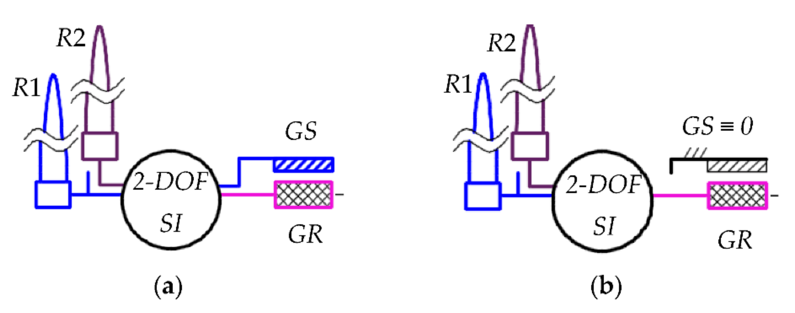
  • The same set of rotors R1 and R2 is used in both wind systems and the same set of mechanical characteristics is considered in modeling these systems, implicitly. Conventionally, R1 is the primary wind rotor and R2—the secondary rotor. The mechanical characteristics of wind turbines can be considered as linear functions with constant coefficients in operation at a constant wind speed. However, the values of these coefficients depend on both the value of wind speed and the characteristics of wind rotor, e.g., the pitch angle of blades.
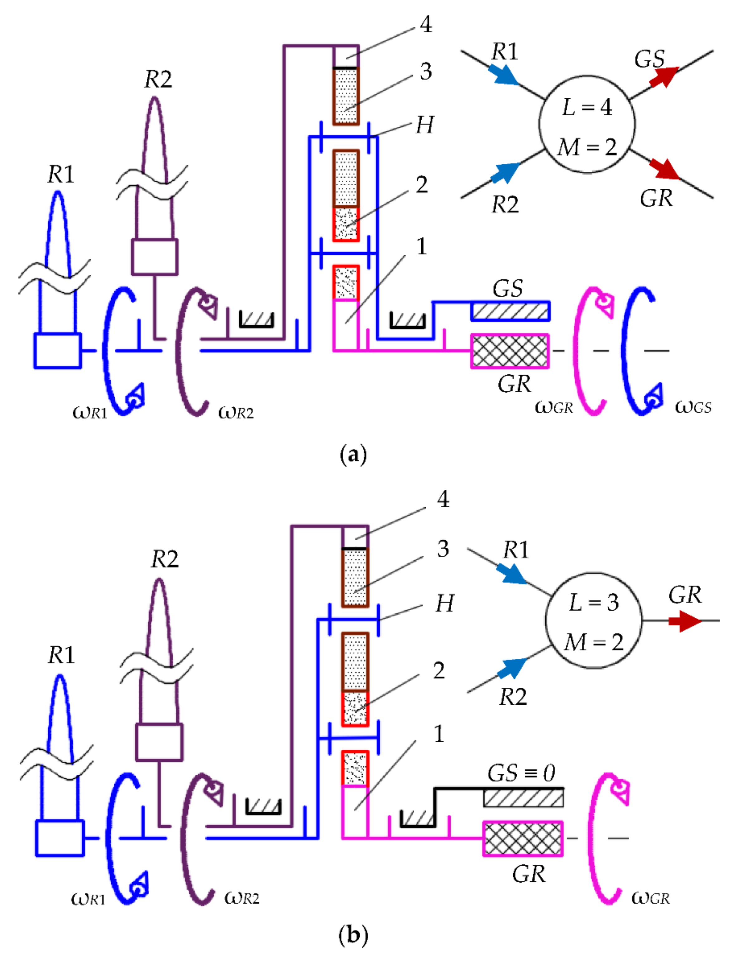
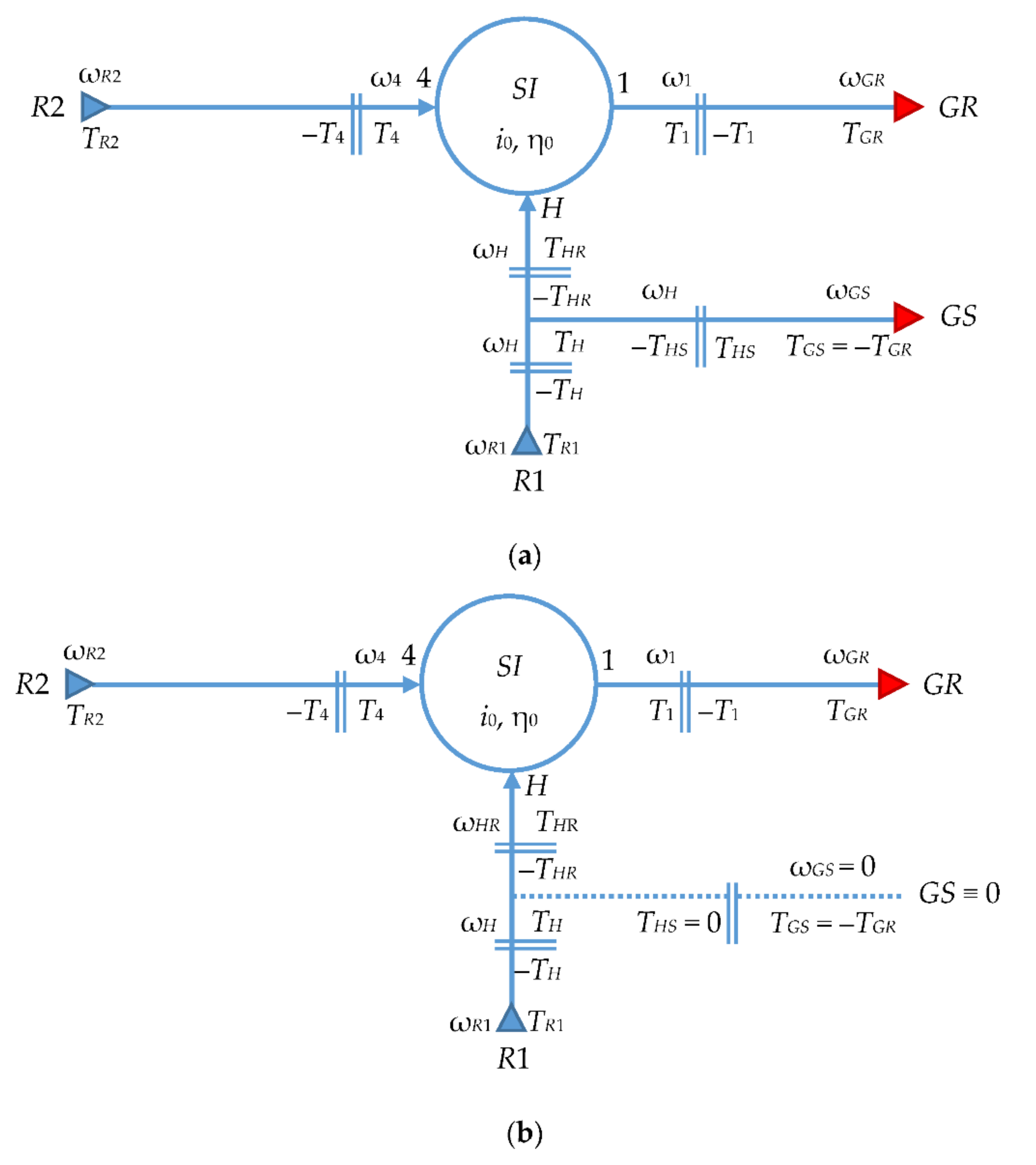
  • In both cases, the speed increaser SI has the same structure and the same values for internal kinematic ratio i0 and internal efficiency η0 [49]. The mechanical transmission is a differential mechanism (2-DOF) with two inputs that are connected to wind rotors R1 and R2, and one or two outputs, through which the mechanical power is transmitted either to rotor GR of the conventional generator or to rotor GR and stator GS of the counter-rotating generator.
  • The counter-rotating electric generator is obtained from the conventional one, by setting the stator GS to rotate in opposite direction to the rotor GR; the two generators have the same mechanical characteristics with respect to the relative speed of rotor GR and stator GS, i.e., ωG = ωGR − ωGS. For the sake of simplicity, the case of direct current (DC) generators is further considered, which are characterized by linear mechanical characteristics with constant coefficients, is further considered.
  • The ratio of angular speeds of wind rotors is denoted by kω = −ωR2R1 > 0. The ratio kω can be adjusted during wind turbine operation by changing the pitch angle of the two rotors R1 and R2, which also changes their mechanical characteristics.
The proposed mathematical model of a wind system with a counter-rotating generator, under the above-mentioned hypotheses, also allows for the description of the system with a conventional electric generator by customizing the state of stator GS: the stator is fixed to the frame after disconnecting it from the speed increaser (see Figure 1).
The case of a planetary speed increaser with cylindrical gears and single serial satellite gears—illustrated in Figure 2 below only through its upper half—is further used to exemplify the mathematical modeling and to identify the relevant properties by numerical simulation of the two wind systems. This transmission consists of two sun gears 1 and 4, meshing with two or more sets of serial satellites 2–3 that are articulated through revolute joints to a satellite carrier H. The speed increaser has two inputs, carrier H and gear 4, which are connected to primary wind rotor R1 and secondary wind rotor R2, respectively, and which can operate with either two outputs (1 and H, Figure 2a) or a single output (1, Figure 2b). The main output is through gear 1, which is connected to rotor GR, while, in the case of the counter-rotating generator, the secondary output H is held fixed to stator GS. As a result, the analyzed planetary transmission has either L = 4 (Figure 2a) or L = 3 (Figure 2b) external connections, two degrees of freedom (M = 2) and, therefore, two independent external speeds (ωH and ω4), as sun gear 1, ring gear 4 and carrier H are mobile bodies.
Wind rotors R1 and R2 have angular speeds ωR1 and ωR2 in opposite directions—a property ensured by setting opposite inclinations of the two rotors’ blades. The two outputs of the speed increaser, by 1 and H, are also counter-rotating due to the kinematic property given by the planetary transmission structure, as highlighted in the next section. Being a differential mechanism, the speed increaser sums up the two input angular speeds ωR1 and ωR2 in an output angular speed ωGR. Angular speed ωGS of stator GS is identical to the input speed of primary rotor R1 (Figure 2a), as a result of the direct connections GS-H-R1.
The analytic modeling of angular speed, torque, power and efficiency of the two wind systems starts from the general case of a wind turbine with a counter-rotating generator and then customized for the particular case of a system with a conventional generator. To this purpose, the kinematic and static correlations of the planetary speed increaser are established on the basis of the block diagrams shown in Figure 3 below and detailed in [33], as well as on the mechanical characteristics of the wind rotors and electric generator, considering the influence of the ratio of input speeds kω = −ωR2R1 on the behavior and performance of the two wind systems. Notations in Figure 3 are: Tx and ωx for torque and angular speed of kinematic body x; i0 and η0 for internal kinematic ratio and internal efficiency of the speed increaser—all of which representing the intrinsic parameters of the planetary transmission [33]. In particular, carrier H is connected to primary rotor R1 by HR shaft and to the generator stator GS by HS shaft (see Figure 3a).
The system with conventional generator, Figure 3b, can be illustrated and analyzed as a particular case of the system with counter-rotating generator, Figure 3a, by disconnecting the shaft HS from the carrier H (i.e., THS = 0) and by fixing the stator GS to the frame (i.e., ωGS = 0).

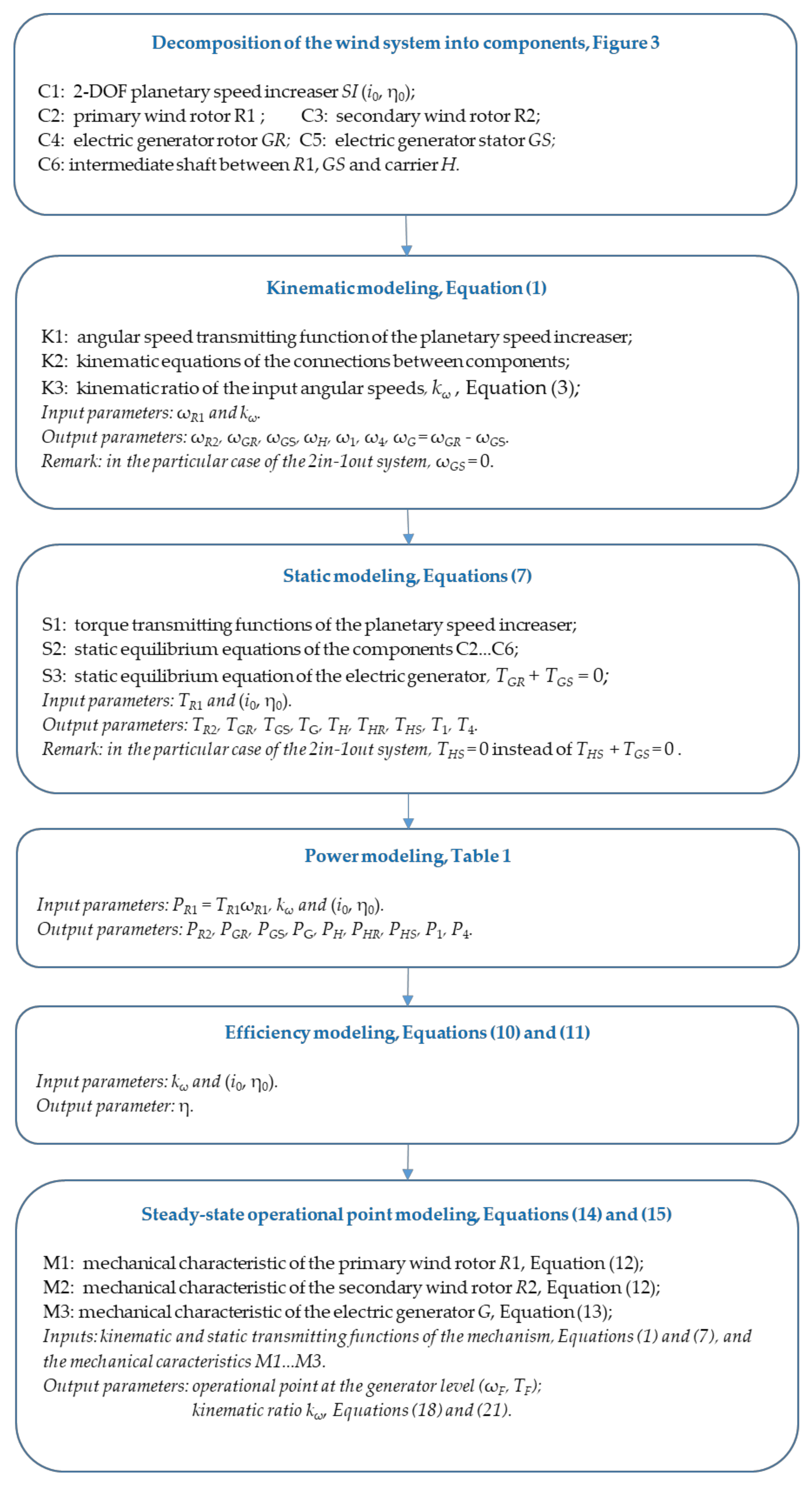
3. Analytic Modeling of Wind Systems

The mathematical modeling of the generalized counter-rotating wind turbine system (with a counter-rotating generator) is performed by applying the method of isolating the components, which involves breaking their connections and replacing them with the appropriate parameters of mechanical power transmitted through these connections. The steps of the applied algorithm for the analytical modeling of the considered wind systems (Figure 2), according to the block diagram and notations in Figure 3, are presented in the flowchart depicted in Figure 4.

3.1. Kinematic Modeling

This modeling aims at establishing the relationships between the dependent angular speeds and the two independent external angular speeds of the speed increaser (ωH and ω4). For this purpose, the speed increaser is characterized by a function of transmitting angular speeds, while each connection (represented by a double line in Figure 3) between the components of the wind system is described through a distinct kinematic equation. Thus, the following system of equations can be written [33]:
ω 1 = ω H 1 i 0 + ω 4 i 0 ;    ω R 1 = ω H ;   ω R 2 = ω 4 ;   ω G R = ω 1 ;   ω G S = ω H .
where the internal kinematic ratio i0 can be calculated from the particular case when H is assumed to be fix, given by relation (2):
i 0 = i 14 H = ω 1 H / ω 4 H = z 4 / z 1 ,
where i 14 H —angular speed transmission ratio from gear 1 to gear 4 when carrier H is considered fixed (or reference body), ωxy—angular speed of body x relative to body y, zj—the number of teeth of gear j; i0 is defined as the kinematic ratio of the fixed axes mechanism that is associated to the planetary gear train, being obtained by reversing the motion relative to the carrier H [49].
Based on the relation between the input angular speeds, as defined by ratio kω:
ω R 2 = k ω ω R 1 ,
the relative angular speed between rotor GR and stator GS of the electric generator, ωG, can be obtained:
ω G = ω G R ω G S = ω R 1 i 0 1 + k ω .
The system of Equation (1) is equally valid for the wind turbine with one output (Figure 2b), except that the last equation has to be replaced by Equation (5):
ω G S = 0
that characterizes the stator GS, which is fixed to the frame after disconnecting it from wind rotor R1. Therefore, the relative angular speed of the electric generator becomes:
ω G = ω G R = ω R 1 1 i 0 1 + k ω .

3.2. Torque Correlation and Efficiency Modeling

According to the diagram in Figure 3, the wind system with counter-rotating generator is modeled by a set of 9 static equilibrium equations consisting of:
  • two torque transmitting functions that are obtained from the static modeling of the differential planetary speed increaser; the number of functions is equal to the mechanism degree of freedom (M = 2). Additionally, the condition of static equilibrium of the planetary transmission can be added as dependent equation for verification purposes;
  • a static equilibrium equation for each of the other five components of the wind system, which are obtained after breaking the connections;
  • the static equilibrium equation of the electric generator, described from the condition that the torque values at rotor GR and stator GS are equal and in opposite direction.
As a result, the set of equations for the differential wind system in Figure 2a—with two counter-rotating inputs and two counter-rotating outputs—can be written as follows:
T H R = T 1 ( 1 i 0 η 0 1 ) ;   T 4 = T 1 i 0 η 0 1 ;    T 1 + T 4 + T H R = 0 ; T R 1 T H = 0 ;   T R 2 T 4 = 0 ;    T G R T 1 = 0 ;    T G S + T H S = 0 ;   T H T H R T H S = 0 ; T G = T G R = T G S ;  
where the internal efficiency of the planetary transmission is:
η 0 = η 14 H = η 12 H · η 23 H · η 34 H = η g 3 ,
where η x y H is the efficiency of the fixed-axis gear mechanism consisting of gears x and y (considering H ≡ 0), while ηg is the efficiency of a component gear pair; in this case, the three cylindrical fixed-axis gear pairs (1‒2, 2‒3, and 3‒4) are considered to have identical efficiency values.
With a differential wind system having two counter-rotating inputs and a conventional generator, Figure 2b, the equation TGS + THS = 0 in system (7) has to be replaced by THS = 0, as the connection of stator GS to wind rotor R1 is broken and then fixed to the frame (ωGS = 0).
In the general case 2 in-2 out, the efficiency of speed increaser can be obtained starting from its definition:
η = ω G R T G R + ω G S T G S ω R 1 T R 1 + ω R 2 T R 2 ,
from which—after some algebraic processing of the systems of Equations (1) and (7)—the efficiency for wind turbines with two counter-rotating rotors and counter-rotating generator can be expressed by:
η = η 0 ,
as well as for wind turbines with conventional generator:
η = η 0 1 i 0 1 + k ω η 0 i 0 1 + k ω .

3.3. Steady-State Operational Point

The operational point of a motor-mechanism-effector type machine is the set of values of the external parameters (kinematic and static) of the mechanism at which the machine operates in steady-state mode. The operational point is obtained by solving the system of equations consisting of the kinematic and static transmitting functions of the speed increaser, Equations (1) and (7), and:
  • the mechanical characteristics of the two wind rotors R1 and R2, described as linear functions with constant coefficients under stationary conditions (constant wind speed, same values of pitch angles):
T R 1 = a R 1 ω R 1 + b R 1 ;      T R 2 = a R 2 ω R 2 + b R 2 ;  
  • the mechanical characteristic of DC generator, represented by a linear function with constant coefficients, describing generator’s torque TG in relation to angular speed ωG. By convention, the torque of the generator is TG = TGR:
T G = a G ω G b G .
Usually, the values of the power parameters on a shaft are first obtained by reducing the mechanical characteristics to that shaft and solving analytically or grapho-analytically the point of intersection between the reduced mechanical characteristics.
Further on, the operational point (F) at the level of the electric generator is analytically determined, by considering the operating angular speed ωF = ωG and the torque TF = TG. Thus, for the two analyzed wind systems, the following expressions of parameters ωF, TF and power PF are obtained:
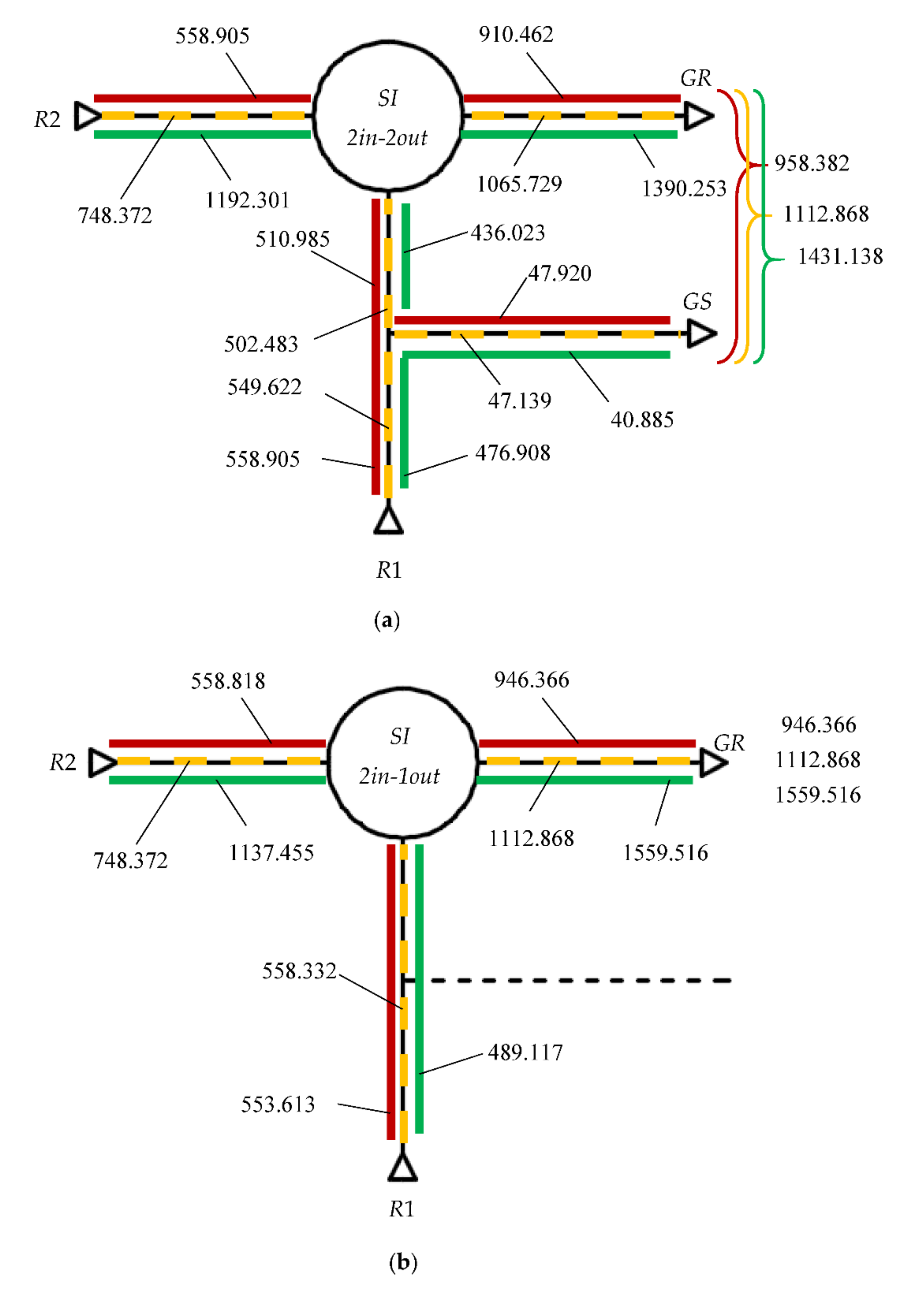
  • for the wind system with counter-rotating generator, Figure 2a:
ω F = b G b R 1 η 0 i 0 a G + a R 1 η 0 i 0 2 1 + k ω ; T F = a G ω F + b G ;   P F = ω F T F .
  • for the wind system with conventional generator, Figure 2b:
ω F = b G b R 1 η 0 i 0 η 0 a G a R 1 η 0 i 0 η 0 1 i 0 1 + k ω ; T F = a G ω F + b G ;      P F = ω F T F .

3.4. Input Angular Speeds Ratio kω

Generally, the input speeds ratio kω depends on the mechanical characteristics of the motor and effector sub-systems and on the intrinsic parameters of the speed increaser (i.e., i0 and η0); in practical applications, ratio kω can be adjusted to a given value by modifying appropriately at least one mechanical characteristic through different approaches, e.g., by changing the pitch angle of the blades, or controlling the electric generator.
The analytical expressions of ratio kω for the two wind systems considered in this comparative analysis can be obtained by processing Equations (1), (3), (4), (6), (7), (12) and (13). Thus, in the case of a system with counter-rotating generator (Figure 2a), it can be concluded from Equation (7) that:
T 1 = T H η 0 i 0 = T 4 η 0 i 0     T H = T 4     T R 2 = T R 1 ; T 4 = T 1 i 0 η 0     T 1 = T G     T R 2 = T G i 0 η 0   .
By replacing the mechanical characteristics of the wind rotors and electric generator from Equations (12) and (13) in Equation (16), and corroborating with Equations (3) and (4), we get:
a R 2 ω R 2 + b R 2 = a R 1 ω R 1 b R 1 ; a R 2 ω R 2 + b R 2 = a G ω g e i 0 η 0 b G i 0 η 0 ; ω R 2 = k ω ω R 1 ; ω G = ω R 1 i 0 1 + k ω ,
which allows one to obtain the expression of kω:
k ω = a R 1 b G i 0 + a R 1 b R 2 η 0 + a G b R 1 i 0 2 + a G b R 2 i 0 2 a R 2 b R 1 η 0 + a G b R 1 i 0 2 + a G b R 2 i 0 2 a R 2 b G i 0   .
Similarly, the following correlations can be written for the system with conventional generator (Figure 2b):
T 1 = T H η 0 η 0 i 0 = T 4 η 0 i 0     T 4 = T H i 0 η 0 i 0     T R 2 = T R 1 i 0 η 0 i 0 ; T 4 = T 1 i 0 η 0     T 1 = T G     T R 2 = T G i 0 η 0 ,
and by combining them with Equations (3), (6), (7), (12) and (13), we get:
a R 2 ω R 2 + b R 2 = a R 1 i 0 η 0 i 0 ω R 1 b R 1 i 0 η 0 i 0 ; a R 2 ω R 2 + b R 2 = a G ω G i 0 η 0 b G i 0 η 0 ; ω R 2 = k ω ω R 1 ; ω G = ω R 1 1 i 0 1 + k ω .
The kω expression is the result of solving the system of Equation (20):
k ω =   a R 1 b G i 0 + a R 1 b R 2 η 0 + a G b R 2 η 0 i 0 a G b R 2 i 0 η 0 i 0 a G b R 1 i 0 1 i 0 a R 2 b G η 0 i 0 + a R 2 b R 1 η 0 + a G b R 1 i 0 2 a G b R 2 i 0 η 0 i 0 .  
The influence of ratio kω on the behavior of the two wind turbines is herein considered by adjusting only the mechanical characteristic of the secondary wind rotor R2 and keeping unchanged the mechanical characteristics of wind rotor R1 and the electric generator. Under these assumptions, coefficients aR2 and bR2 become variables which are dependent on both ratio kω and the constant coefficients of the mechanical characteristic of primary rotor R1.
Thus, the following equation is obtained for the wind system with counter-rotating generator (Figure 2a), by considering the equality TR2 = −TR1 from Equation (16):
ω R 1 a R 1 + a R 2 k ω + b R 1 + b R 2 = 0 ,
where ωR1 is the independent parameter; this equality is mathematically satisfied only if the following two conditions are met simultaneously:
a R 1 + a R 2 k ω = 0 ; b R 1 + b R 2 = 0 ,
which leads to the solution:
a R 2 = a R 1 / k ω ; b R 2 = b R 1   .
Similarly, for the wind turbine system with conventional generator (Figure 2b), the starting point is established from the equality deduced in Equation (19):
T R 2 = T R 1 i 0 η 0 i 0   ,
from which Equation (26) is obtained as function of ωR1:
ω R 1 a R 1 i 0 + a R 2 ( η 0 i 0 ) k ω b R 1 i 0 + b R 2 η 0 i 0 = 0 ,
as well as the expressions of coefficients aR2 and bR2 are determined:
a R 2 = a R 1 i 0 / η 0 i 0 k ω ; b R 2 = b R 1 i 0 / η 0 i 0   .
For comparison, the relations for the kinematic and static parameters of the two wind systems are tabulated below (see Table 1); the relations are established as functions of the parameters of primary wind rotor R1 in the analytical modeling presented above.
The analytical relations for the wind system with conventional electric generator (2 in-1 out, last column of Table 1) were obtained by the appropriate customization of the general model described for the case of the system with counter-rotating generator, i.e., breaking the connection between H and SG (i.e., THS = 0) and fixing the stator SG to the frame (i.e., ωSG = 0). The analysis of the relations from Table 1 can highlight the following properties of wind systems of 2 in-2 out type compared to 2 in-1 out type systems:
-
achieve a kinematic amplification ratio, in absolute value, higher than 1 (as both the ratios i0 and kω have positive values);
-
have a higher efficiency, which does not depend on the kinematic configuration of the speed increaser and which is equal to the internal efficiency η0;
-
ensure the operation with higher angular speeds ωG and powers PG of the electric generator, for the same power of the primary wind rotor PR1 = TR1 ωR1 ;
-
the wind rotor R2 operates at lower torques and powers.

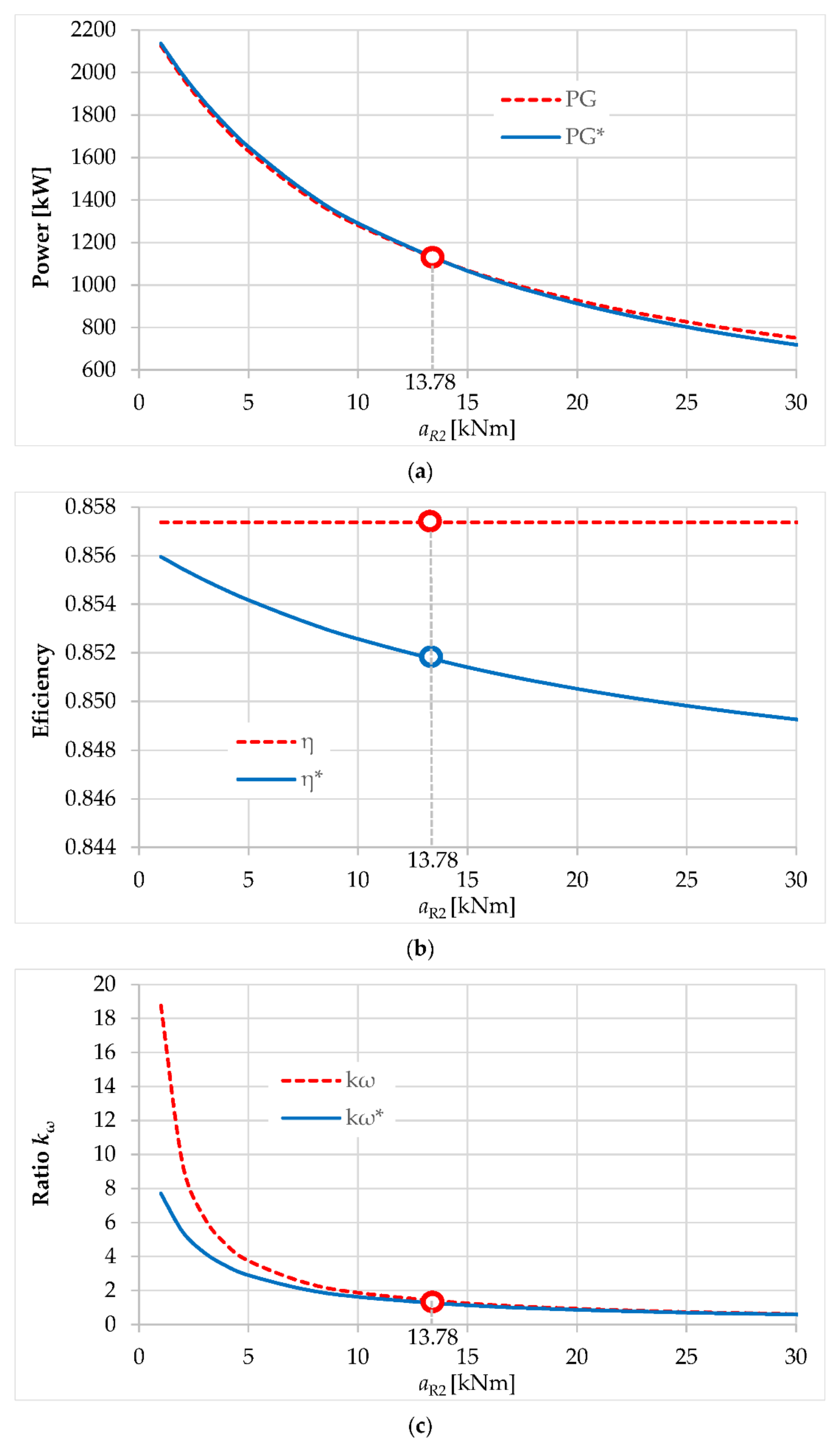
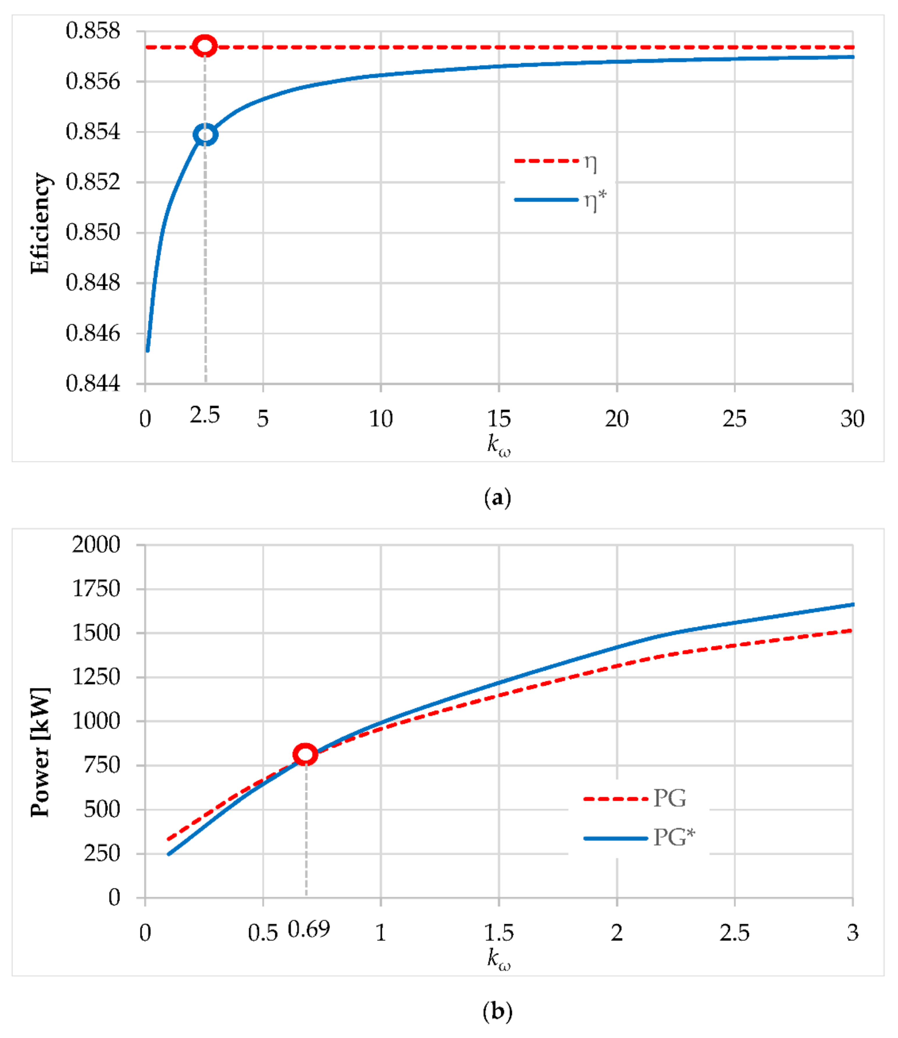
4. Numerical Simulations and Discussions

The comparative analysis of the performance of the two wind systems presented above, which integrate the same planetary speed increaser (i.e., the same values of the intrinsic parameters i0 and η0), is performed under equivalence conditions, by considering the following three numerical simulation scenarios:
Scenario A: the two wind turbines use the same wind rotors R1 and R2, as well as the same electric generator—used as a counter-rotating generator with the 2 in-2 out wind system (Figure 2a) and as a conventional generator with the 2 in-1 out wind system (Figure 2b). In this scenario, rotors R1 and R2 are identical and, therefore, have identical mechanical characteristics with the same constant coefficients.
Scenario B: very similar to Scenario A, except that rotors R1 and R2 are different and, as a result, they have mechanical characteristics with different constant coefficients.
Scenario C: derived from Scenario B, with the difference that secondary wind rotors R2 are adjusted differently in the two wind turbines (coefficients of mechanical characteristics for rotors R2 are different), with a view to providing the same value of ratio kω.
These scenarios aim at determining the operational points of the two wind turbines, i.e., the values of angular speed and torque for the external connections of the mechanism, which allow the calculation of the efficiency and output power. Therefore, Equations (14) and (15) are used to obtain the operational point of the rotor GR shaft, which allows the identification of the operational point of the primary wind rotor R1 and then all the other parameters, based on the relations in Table 1.
The intrinsic parameters of the planetary speed increaser remain constant in all scenarios, the following values being considered in the simulations: i0 = 10 and η 0 = η g 3 = 0.95 3 = 0.857 .

4.1. Scenario A

In this scenario, the two wind turbines are characterized by the following features, see Rel. (7):
-
wind rotors R1 and R2 are identical, since they have the same mechanical characteristics: TR1 = −aR1ωR1 + bR1 = −18.763 ωR1 − 204.81 and TR2 = −aR2ωR2 + bR2 = −18.763 ωR2 + 204.81;
-
electric generators have the same mechanical characteristic −TG = −aGωR1 − bG = −;0.4ωG − 35.
The results of the numerical simulations for the operational points of the two wind turbines are tabulated below (see Table 2).
From these numerical results, the following conclusions can be drawn: compared to the 2 in-1 out wind system, the wind turbine with counter-rotating generator (2 in-2 out) operates at a higher efficiency (85.73% vs. 85.07%), ensures a higher amplification ratio in absolute value (20.00 vs. 17.21) and has a higher power by approx. 1.3% (958.38 vs. 946.37). Both wind rotors have similar lower angular speeds and higher torques, which leads to close input powers. As a result, when using identical wind rotors R1 and R2 in both systems and constant intrinsic parameters of the speed increaser and the considered mechanical characteristics, the wind turbine with a counter-rotating generator ensures slightly higher performance than the wind turbine with a conventional generator. Although preferred in terms of performance, the 2 in-2 out wind turbine can be surpassed by the 2 in-1 out turbine due to an increased complexity of the counter-rotating electric generator—if an economically-grounded multicriteria analysis might be performed.

4.2. Scenario B

The facts and figures in Scenario A change significantly by using secondary wind rotors which are different from the primary ones. Therefore, the Scenario B aims at identifying the operational point of the two wind turbines by considering, for both types of wind system:
-
the same wind rotor R1, with the mechanical characteristic TR1 = −aR1ωR1 + bR1 = −18.763 ωR1 − 204.81
-
the same wind rotor R2, with the mechanical characteristic TR2 = −aR2ωR2 + bR2 = −18.763 ωR2 + 204.81; established from the condition that the two wind turbines generate equal power;
-
the same electric generator, with the mechanical characteristic TG = −aGωR1 − bG = −0.4ωG − 35.
Under these conditions, the two wind turbines are stabilized in steady-state at the operational point values listed in Table 3 below.
Under the condition of equal output power, used for driving the electric generator, it is found that wind rotor R2 extracts the same power from the wind in both systems, while primary wind rotor R1 operates at higher parameters with 2 in-1 out wind turbine. Instead, the wind system with a counter-rotating generator has slightly better efficiency (85.74% vs. 85.16%), which provides the energy compensation required to obtain a power output equal to that of the system with a conventional generator. Choosing the secondary wind rotor (by setting the coefficient aR2) is a challenging task for designers, which can lead to changing the option for one or the other type of wind turbine. Parameters marked by asterisk (*) in the following diagrams, Figure 5, refer to the wind turbine with a conventional generator.
According to Figure 5a, the wind turbine with a conventional generator ensures an output power (PG* curve) higher than that of the 2 in-2 out turbine, for values of coefficient aR2 < 13.78, and generates power values significantly close to those of the turbine with a counter-rotating generator (PG curve), for values of coefficient aR2 > 13.78. The efficiency of the conventional turbine decreases with the increase of values for aR2 (see Figure 5b). In all instances, the wind turbine with a counter-rotating generator is stabilized at higher values of ratio kω, i.e., a greater difference between input speeds, but with less significant differences for aR2 > 13.78 (see Figure 5c).
Thus, it should be emphasized that the performance of the two wind systems is significantly influenced by the external mechanical characteristics, modified in this study by changing the coefficient values aR1 = aR2.

4.3. Scenario C

The Scenario C is an extension of the Scenario B, by ensuring the additional condition of obtaining the same ratio kω for both wind turbines. Under the conditions of maintaining the same primary wind rotor R1 and the same electric generator as in Scenarios A and B, this goal can only be achieved if the secondary wind rotors R2 are different, i.e., aR2a*R2 and bR2b*R2. As a case study, the target value of ratio kω = 2.5 is further considered and, therefore, the coefficients of the mechanical characteristics of rotors R2 can be calculated, by means of Equations (24) and (27). The values of the steady-state operational points for the two wind turbines are displayed in Table 4 below. As in Scenario B, the parameters marked by * refer to the wind system with a conventional generator.
According to the results in Table 2, Table 3 and Table 4 and Figure 6a, it can be concluded that the efficiency of the speed increaser is higher with systems having a counter-rotating generator, as a result of in-parallel transmission of the output mechanical power, compared to wind systems with a conventional generator. The efficiency dependence on ratio kω—described by Equations (10) and (11) and illustrated in Figure 6a—highlights the fact that efficiency of a 2 in-2 out wind system is constant and always higher than that achieved by a 2 in-1 out system, whose values tend to infinity toward this constant value. Thus, the efficiency of the two wind systems can have close values only for very high values of kω, which is not justified in the operation of a wind system with counter-rotating rotors.
As in Scenario B, the wind turbine with a counter-rotating generator has higher energy performance for low values of ratio kω and output power, implicitly (Figure 6b). Instead, the wind turbine with a conventional generator proves to be more efficient for higher values of ratio kω and output power.
To conclude the discussions for the three numerical simulation scenarios, the power flows for both wind systems with counter-rotating electric generator (Figure 7a) vs. conventional generator (Figure 7b) are comparatively represented in Figure 7. It is noticeable for both systems the increase of the output power from Scenario A to Scenario C, as well as the effectiveness of the 2 in-2 out system at lower powers and, respectively, of the 2 in-1 out system at higher powers.

5. Conclusions

The paper presented a comparative study of the energy performance of wind turbines with two counter-rotating rotors (R1 and R2) and differential speed increaser, in the functional configurations with counter-rotating vs. conventional generator. To this end, the analytical modeling of the operational point of the two types of wind system has been presented and numerically analyzed in three scenarios, with distinct situations regarding the way the secondary wind rotor R2 characteristic is chosen: R2 identical to the primary wind rotor R1 (Scenario A); R2 different from R1, and R2 identical in both applications (Scenario B); and R2 different from R1, and R2 different in the two applications (Scenario C).
According to the analyzed scenarios, the comparative study of the numerical results allows drawing the following final conclusions:
  • The differential wind system with a counter-rotating electric generator, which is characterized by in-parallel transmission of power at both input and output, always ensures better efficiency of mechanical power transmission from inputs to outputs, compared to the wind system with a conventional generator. In the case of counter-rotating outputs, the efficiency of the wind system is equal to the internal efficiency η0 of the planetary transmission; instead, the efficiency of the wind turbine with a conventional generator is significantly influenced by system parameters (i.e., ratio kω, coefficients of mechanical characteristics, kinematic ratio i0), the value η0 being the upper limit of efficiency variation for this type of wind turbine.
  • The energy response of the two types of wind system depends significantly on the characteristics of the selected wind rotors and electric generator. Thus, the advantage of better mechanical efficiency of wind turbines with a counter-rotating generator is accompanied by higher energy performance only in certain system configurations—generally, in the range of lower power. Considering the higher complexity of counter-rotating electric generators, due to their mobile stator, the designers’ decision to choose a type of counter-rotating wind turbine seems to be a compromise between technical, energy and economic performance.
The proposed models are useful in the synthesis of differential speed increasers with counter-rotating inputs and outputs, which ensure higher output speed by speed-adding, in conditions of higher efficiency. Considering these facts, the findings emerged from this contrastive approach might prove particularly useful to wind system designers in selecting the most adequate technical solution, depending on the amount of power needed and the wind potential in the area of implementation.
In the future, the authors intend to generalize the modeling of the behavior of counter-rotating wind turbines with counter-rotating electric generator vs. conventional generator in both cases of operation, as a 2-DOF (speed-adding) and a 1-DOF (torque-adding) system, followed by experimental validation of analytical results by developing and using an versatile rig to test these types of counter-rotating wind turbines.

Author Contributions

Conceptualization, R.S. and M.N.; Data curation, R.S., M.N. and C.J.; Formal analysis, R.S, M.N. and C.J.; Investigation, R.S., M.N. and C.J.; Methodology, R.S., M.N., C.J. and O.M.; Software, R.S. and M.N.; Supervision, M.N., C.J. and O.M.; Validation, M.N. and C.J.; Visualization, R.S., M.N., C.J. and O.M.; Writing—original draft, R.S. and M.N.; Writing—review & editing, C.J. and O.M. All authors have read and agreed to the published version of the manuscript.

Funding

This research received no external funding.

Acknowledgments

The comments, suggestions and recommendations for future research by the anonymous reviewers are gratefully acknowledged.

Conflicts of Interest

The authors declare no conflict of interest.

Nomenclature

SISpeed increaserDOFDegree of freedom
R1Primary wind rotorMMechanism mobility
R2Secondary wind rotorLTotal number of inputs and outputs
PPowerGElectric generator
ωAngular speedGRElectric generator rotor
TTorqueGSElectric generator stator
kωRatio of the input angular speedsiKinematic ratio
zNumber of gear teethi0Internal kinematic ratio
HSatellite carrieriaAmplification kinematic ratio
FOperational pointηEfficiency of the speed increaser
aAngular speed coefficientη0Internal efficiency
bTorque coefficientηgEfficiency of a gear pair

References

  1. Wacinski, A.; Sàrl, E. Drive Device for a Windmill Provided with Two Counter–Rotative Propellers. U.S. Patent 7,384,239, 6 September 2008. [Google Scholar]
  2. Brander, M. Bi-Directional Wind Turbine. U.S. Patent 0,197,639 A1, 21 August 2008. [Google Scholar]
  3. Jaliu, C.; Climescu, O.; Saulescu, R. Speci fic features of a counter-rotating transmission for renewable energy systems. Environ. Eng. Manag. J. 2011, 10, 1105–1113. [Google Scholar] [CrossRef]
  4. Oprina, G.; Chihaia, R.A.; El-Leathey, L.A.; Nicolaie, S.; Babutanu, C.A.; Voina, A. A review on counter-rotating wind tur-bines development. J. Sustain. Energy 2016, 7, 91–98. [Google Scholar]
  5. Shin, C. Multi-Unit Rotor Blade System Integrated Wind Turbine. U.S. Patent 5,876,181, 2 March 1999. [Google Scholar]
  6. Muhtadi, R.Z.; Bramantya, M.A. Experimental study of local pitch variations on electric power generated by counter rotating wind turbine with single generator without gearbox. IOP Conf. Ser. Mater. Sci. Eng. 2018, 434, 012176. [Google Scholar] [CrossRef]
  7. Li, Z.; Wang, Y.; Xiao, H. Experimental study on structures of counter-rotating wind turbines. In Proceedings of the 2013 International Conference on Materials for Renewable Energy and Environment, Chengdu, China, 19–21 August 2013; Volume 1, pp. 368–372. [Google Scholar] [CrossRef]
  8. Pamuji, D.; Bramantya, M. Numerical Study on the Performance Of 2-Bladed and 3-Bladed Counter Rotating Wind Turbines. J. Jpn. Soc. Appl. Electromagn. Mech. 2019, 27, 169–174. [Google Scholar] [CrossRef] [Green Version]
  9. Didane, D.H.; Rosly, N.; Zulkafli, M.F.; Shamsudin, S.S. Performance evaluation of a novel vertical axis wind turbine with coaxial contra-rotating concept. Renew. Energy 2018, 115, 353–361. [Google Scholar] [CrossRef]
  10. West, R. Wind Turbine System. U.S. Patent 10,316,820 B2, 11 June 2019. [Google Scholar]
  11. Vasel-Be-Hagh, A.; Archer, C.L. Wind farms with counter-rotating wind turbines. Sustain. Energy Technol. Assess. 2017, 24, 19–30. [Google Scholar] [CrossRef]
  12. Jaliu, C.; Diaconescu, D.V.; Neagoe, M.; Saulescu, R. Dynamic features of speed increasers from mechatronic wind and hydro systems. Part II. Dynamic aspects. In Proceedings of the Second European Conference on Mechanism Science EUCOMES 08, Casino, Italy, 17–20 September 2008; Springer: Dordrecht, The Netherlands, 2008; pp. 365–373, ISBN 987-1-4020-8914-5. [Google Scholar]
  13. Bevington, C.M.; Bywaters, G.L.; Coleman, C.C.; Costin, D.P.; Danforth, W.L.; Lynch, J.A.; Rolland, R.H. Wind Turbine Having a Direct-Drive Drivetrain. U.S. Patent 7,431,567 B1, 7 October 2008. [Google Scholar]
  14. Marjanovic, N.; Isailovic, B.; Marjanovic, V.; Milojevic, Z.; Blagojevic, M.; Bojic, M. A practical approach to the optimization of gear trains with spur gears. Mech. Mach. Theory 2012, 53, 1–16. [Google Scholar] [CrossRef]
  15. Pastor, D.G.S.B.; Nalianda, D.; Sethi, V.; Midgley, R.; Rolt, A.; Novelo, D.A.B. Preliminary Design Framework for the Power Gearbox in a Contra-Rotating Open Rotor. J. Eng. Gas Turbines Power 2021, 143, 041022. [Google Scholar] [CrossRef]
  16. Jelaska, D.; Podrug, S.; Perkušić, M. A novel hybrid transmission for variable speed wind turbines. Renew. Energy 2015, 83, 78–84. [Google Scholar] [CrossRef]
  17. Saulescu, R.; Neagoe, M.; Munteanu, O.; Cretescu, N. Performance analysis of a novel planetary speed increaser used in single-rotor wind turbines with counter-rotating electric generator. IOP Conf. Ser. Mater. Sci. Eng. 2016, 147, 012090. [Google Scholar] [CrossRef]
  18. Neagoe, M.; Saulescu, R.; Jaliu, C.; Cretescu, N. Novel Speed increaser used in counter-rotating wind turbines. In New Advances in Mechanisms, Mechanical Transmissions and Robotics, Mechanisms and Machine Science 46; Springer: Berlin, Germany, 2017; pp. 143–151. [Google Scholar] [CrossRef]
  19. Jaliu, C.; Diaconescu, D.V.; Neagoe, M.; Saulescu, R. Dynamic features of speed increasers from mechatronic wind and hydro systems. Part I. Structure Kinematics. In Proceedings of the Second European Conference on Mechanism Science EUCOMES 08, Casino, Italy, 17–20 September 2008; Springer: Dordrecht, The Netherlands, 2008; pp. 355–363, ISBN 987-1-4020-8914-5. [Google Scholar]
  20. Erturk, E.; Sivrioglu, S.; Bolat, F.C. Analysis Model of a Small Scale Counter-Rotating Dual Rotor Wind Turbine with Double Rotational Generator Armature. Int. J. Renew. Energy Res. 2018, 8, 1849–1858. [Google Scholar]
  21. Bharani, R.; Sivaprakasam, A. A Review Analysis on Performance and Classification of Wind Turbine Gearbox Technologies. IETE J. Res. 2020, 1–15. [Google Scholar] [CrossRef]
  22. Fan, Z.; Zhu, C.; Li, X.; Liang, C. The transmission characteristic for the improved wind turbine gearbox. Energy Sci. Eng. 2019, 7, 1368–1378. [Google Scholar] [CrossRef] [Green Version]
  23. Qiu, J.; Liu, B.; Dong, H.; Wang, D. Type Synthesis of Gear-box in Wind Turbine. Procedia Comput. Sci. 2017, 109, 809–816. [Google Scholar] [CrossRef]
  24. Climescu, O.; Jaliu, C.; Saulescu, R. Comparative Analysis of Horizontal Small Scale Wind Turbines for a Specific Applica-tion. In Proceedings of the 14th IFToMM World Congress, Taipei, Taiwan, 25–30 October 2015. [Google Scholar] [CrossRef]
  25. Saulescu, R.; Neagoe, M.; Jaliu, C. Improving the Energy Performance of Wind Turbines Implemented in the Built Environment Using Counter-Rotating Planetary Transmissions. IOP Conf. Ser. Mater. Sci. Eng. 2016, 147, 012089. [Google Scholar] [CrossRef]
  26. Saulescu, R.; Jaliu, C.; Neagoe, M. Structural and Kinematic Features of a 2 DOF Speed Increaser for Renewable Energy Systems. Appl. Mech. Mater. 2016, 823, 367–372. [Google Scholar] [CrossRef]
  27. Saulescu, R.; Neagoe, M.; Jaliu, C.; Munteanu, O. Comparative Analysis of Two Wind Turbines with Planetary Speed Increaser in Steady-State. Appl. Mech. Mater. 2016, 823, 355–360. [Google Scholar] [CrossRef]
  28. Saulescu, R.; Jaliu, C.; Munteanu, O.; Climescu, O. Planetary Gear for Counter-Rotating Wind Turbines. Appl. Mech. Mater. 2014, 658, 135–140. [Google Scholar] [CrossRef]
  29. Saulescu, R.; Jaliu, C.; Climescu, O.; Diaconescu, D. On the use of 2 DOF planetary gears as “speed increaser” in small hydros and wind turbines. In Proceedings of the ASME International Design Engineering Technical Conferences & Computers and Information in Engineering Conference IDETC/CIE 2011, Washington, DC, USA, 25–31 August 2011. [Google Scholar]
  30. Herzog, R.; Schaffarczyk, A.P.; Wacinski, A.; Zürcher, O. Performance and stability of a counter–rotating windmill using a planetary gearing: Measurements and Simulation. In Proceedings of the European Wind Energy Conference & Exhibition, Warsaw, Poland, 20–23 April 2010. [Google Scholar]
  31. Neagoe, M.; Saulescu, R.; Jaliu, C. Design and Simulation of a 1 DOF Planetary Speed Increaser for Counter-Rotating Wind Turbines with Counter-Rotating Electric Generators. Energies 2019, 12, 1754. [Google Scholar] [CrossRef] [Green Version]
  32. Saulescu, R.; Neagoe, M.; Jaliu, C. Conceptual Synthesis of Speed Increasers for Wind Turbine Conversion Systems. Energies 2018, 11, 2257. [Google Scholar] [CrossRef] [Green Version]
  33. Neagoe, M.; Jaliu, C.; Saulescu, R.; Simionescu, P. Steady-State Response of a Dual-Rotor Wind Turbine with Counter-Rotating Electric Generator and Planetary Gear Increaser. In Proceedings of the USCToMM MSR 2020, Rapid City, SD, USA, 14–16 May 2020; pp. 106–115. [Google Scholar] [CrossRef]
  34. Zhao, M.; Ji, J. Dynamic Analysis of Wind Turbine Gearbox Components. Energies 2016, 9, 110. [Google Scholar] [CrossRef] [Green Version]
  35. Dong, H.; Zhang, C.; Wang, D.; Xu, S.; Qiu, J. Dynamic characteristics of gear box with PGT for wind turbine. Procedia Comput. Sci. 2017, 109, 801–808. [Google Scholar] [CrossRef]
  36. Vázquez-Hernández, C.; Serrano-González, J.; Centeno, G. A Market-Based Analysis on the Main Characteristics of Gearboxes Used in Onshore Wind Turbines. Energies 2017, 10, 1686. [Google Scholar] [CrossRef] [Green Version]
  37. Farahani, E.; Hosseinzadeh, N.; Ektesabi, M. Comparison of fault-ride-through capability of dual and single-rotor wind turbines. Renew. Energy 2012, 48, 473–481. [Google Scholar] [CrossRef]
  38. Kutt, F.; Blecharz, K.; Karkosiński, D. Axial-Flux Permanent-Magnet Dual-Rotor Generator for a Counter-Rotating Wind Turbine. Energies 2020, 13, 2833. [Google Scholar] [CrossRef]
  39. Mirnikjoo, S.; Abbaszadeh, K.; Abdollahi, S.E. Multi-Objective Design Optimization of a Double-Sided Flux Switching Permanent Magnet Generator for Counter-Rotating Wind Turbine Applications. IEEE Trans. Ind. Electron. 2020, 1. [Google Scholar] [CrossRef]
  40. Zhamalov, A.Z.; Obozov, A.D.; Kunelbaev, M.M.; Baikadamova, L.S. Capacity and Power Characteristics of Disk Generator with Counter-Rotation of Double-Rotor Wind Turbine. Middle-East J. Sci. Res. 2013, 15, 1655–1662. [Google Scholar] [CrossRef]
  41. Kanemoto, T.; Galal, A.M. Development of Intelligent Wind Turbine Generator with Tandem Wind Rotors and Double Rotational Armatures. JSME Int. J. Ser. B 2006, 49, 450–457. [Google Scholar] [CrossRef] [Green Version]
  42. Caiozza, J. Wind Driven Electric Generator Apparatus. U.S. Patent 7,227,276 B2, 5 June 2007. [Google Scholar]
  43. Pacholczyk, M.; Karkosiński, D. Parametric Study on a Performance of a Small Counter-Rotating Wind Turbine. Energies 2020, 13, 3880. [Google Scholar] [CrossRef]
  44. Saulescu, R.; Neagoe, M.; Cretescu, N. Comparative analysis of two wind turbines with counter-rotating vs. fixed-stator electric generator. IOP Conf. Ser. Mater. Sci. Eng. 2020, 997, 012091. [Google Scholar] [CrossRef]
  45. Fan, G.-F.; Qing, S.; Wang, H.; Hong, W.-C.; Li, H.-J. Support Vector Regression Model Based on Empirical Mode Decomposition and Auto Regression for Electric Load Forecasting. Energies 2013, 6, 1887–1901. [Google Scholar] [CrossRef]
  46. Hong, W.-C.; Fan, G.-F. Hybrid Empirical Mode Decomposition with Support Vector Regression Model for Short Term Load Forecasting. Energies 2019, 12, 1093. [Google Scholar] [CrossRef] [Green Version]
  47. Pfaffel, S.; Faulstich, S.; Rohrig, K. Performance and Reliability of Wind Turbines: A Review. Energies 2017, 10, 1904. [Google Scholar] [CrossRef] [Green Version]
  48. Neagoe, M.; Saulescu, R.; Jaliu, C.; Simionescu, P.A. A Generalized Approach to the Steady-State Efficiency Analysis of Torque-Adding Transmissions Used in Renewable Energy Systems. Energies 2020, 13, 4568. [Google Scholar] [CrossRef]
  49. Miloiu, G.; Dudita, F.; Diaconescu, D. Modern Mechanical Transmissions; Tehnica: Bucharest, Romania, 1980. (In Romanian) [Google Scholar]
Figure 1. Block diagrams of the differential counter-rotating wind systems that are considered in the comparative analysis: (a) with counter-rotating generator; (b) with conventional generator.
Energies 14 02594 g001
Figure 2. Structural and block diagrams for wind systems with two counter-rotating inputs, a differential planetary speed increaser and: (a) counter-rotating generator; (b) conventional generator.
Energies 14 02594 g002
Figure 3. Block diagram of the differential wind system with two inputs and: (a) two outputs; (b) one output.
Energies 14 02594 g003
Figure 4. Algorithm for analytical modeling of the generalized 2-DOF dual-rotor counter-rotating wind systems.
Energies 14 02594 g004
Figure 5. Variation with respect to aR2 coefficient of: (a) output power, (b) efficiency and (c) ratio kω, in both wind systems.
Energies 14 02594 g005
Figure 6. Variation with respect to ratio kω of: (a) efficiency and (b) output power, in both wind systems.
Energies 14 02594 g006
Figure 7. Power flow in the Scenarios A (continuous red line), B (yellow dashed line) and C (continuous green line) through: (a) 2 in-2 out wind system; (b) 2 in-1 out wind system.
Energies 14 02594 g007
Table 1. The analytical expressions of the kinematic and static parameters of the wind systems.
ParameterSymbolWind System
2 in-2 out,
Figure 2a
Wind System
2 in-1 out,
Figure 2b
Amplification kinematic ratio i a = ω G ω R 1 i 0 1 + k ω 1 i 0 1 + k ω
Efficiency η η 0 η 0 1 i 0 1 + k ω η 0 i 0 1 + k ω  
Angular speed of the generator ω G = ω G R ω G S ω R 1 i 0 1 + k ω ω R 1 1 i 0 1 + k ω
Generator torque T G = T G R T R 1 η 0 η 0 i 0 T R 1 η 0 η 0 i 0
Generator power P G = T G   ω G T R 1 ω R 1 η 0 i 0 1 + k ω η 0 i 0 T R 1 ω R 1 η 0 1 i 0 1 + k ω η 0 i 0
Angular speed of the generator rotor ω G R ω R 1 1 i 0 1 + k ω ω R 1 1 i 0 1 + k ω
Generator rotor torque T G R T R 1 η 0 i 0 T R 1 η 0 i 0
Generator rotor power P G R T R 1 ω R 1 η 0 1 i 0 k ω + 1 i 0 T R 1 ω R 1 η 0 1 i 0 k ω + 1 i 0
Angular speed of the generator stator ω G S ω R 1 0
Generator stator torque T G S T R 1 η 0 i 0 T R 1 η 0 i 0
Generator stator power P G S T R 1 ω R 1 η 0 i 0 0
Angular speed of the carrier H ω H ω R 1 ω R 1
H carrier torque T H T R 1 T R 1
H carrier power P H T R 1 ω R 1 T R 1 ω R 1
Angular speed of the shaft HR ω H R ω R 1 ω R 1
HR shaft torque T H R T R 1 i 0 η 0 i 0 T R 1
HR shaft power P H R T R 1 ω R 1 i 0 η 0 i 0 T R 1 ω R 1
Angular speed of shaft HS ω H S ω R 1 0
HS shaft torque T H S T R 1 η 0 i 0 T R 1 η 0 i 0
HS shaft power P H S T R 1 ω R 1 η 0 i 0 0
Angular speed of gear 4 ω 4 k ω ω R 1 k ω ω R 1
Torque on gear 4 T 4 T R 1 T R 1 i 0 i 0 η 0
Power of gear 4 P 4 k ω T R 1 ω R 1 ω R 1 T R 1 k ω i 0 i 0 η 0
Table 2. The values of the parameters related to the steady-state operational point for Scenario A.
ParameterWind System 2 in-2 out,
Figure 2a
Wind System 2 in-1 out,
Figure 2b
ω R 1 [s−1]−5.470−5.989
T R 1 [kNm]−102.176−92.438
P R 1 [kW]558.905553.613
ω R 2 [s−1]5.4705.527
T R 2 [kNm]102.176101.106
P R 2 [kW]558.905558.818
ω G [s−1]109.401109.171
T G [kNm]−8.760−8.669
P G [kW]−958.382−946.366
η 0.85730.8507
k ω 1.0000.923
i a = ω G / ω R 1 −20.000−17.209
aR1 = aR2 = 18.763 [kNms]; bR1 = bR2 = −204.81 [kNm]; aG = 0.4 [kNms]; bG = 35 [kNm]; i0 = 10; η0 = 0.857.
Table 3. The values of the parameters related to the steady-state operational point for Scenario B.
ParameterWind System 2 in-2 out,
Figure 2a
Wind System 2 in-1 out,
Figure 2b
ω R 1 [s−1]−4.754−5.283
T R 1 [kNm]−115.604−105.693
P R 1 [kW]549.622558.332
ω R 2 [s−1]6.4746.474
T R 2 [kNm]115.604115.604
P R 2 [kW]748.372748.372
ω G [s−1]112.279112.279
T G [kNm]−9.912−9.912
P G [kW]−1112.868−1112.868
η 0.85740.8516
k ω 1.3621.225
i a = ω G / ω R 1 −23.616−21.255
aR1 = 18.763 [kNms]; ]; bR1−204.81 [kNm]; aR2 = 13.780 [kNms]; bR2 = 204.81 [kNm]; aG = 0.4 [kNms]; bG = 35 [kNm]; i0 = 10; η0 = 0.857.
Table 4. The values of the parameters related to the steady-state operational point for Scenario C.
ParameterWind System 2 in-2 out,
Figure 2a
Wind System 2 in-1 out,
Figure 2b
ω R 1 [s−1]−3.367−3.529
T R 1 [kNm]−141.630−138.592
P R 1 [kW]476.908489.117
ω R 2 [s−1]8.4188.823
T R 2 [kNm]141.630151.589
P R 2 [kW]1192.3011337.455
ω G [s−1]117.857119.992
T G [kNm]−12.143−12.997
P G [kW]−1431.138−1559.516
η 0.85740.8538
i a = ω G / ω R 1 −35.000−34.000
aR1 = 18.763 [kNms]; ]; bR1−204.81 [kNm]; aR2 = 7.505 [kNms]; bR2 = 204.81 [kNm]; kω = 2.5; a*R2 = 8.209 [kNms]; b*R2 = 224.016 [kNm]; aG = 0.4 [kNms]; bG - 35 [kNm]; i0 = 10; η0 = 0.857.
Publisher’s Note: MDPI stays neutral with regard to jurisdictional claims in published maps and institutional affiliations.

