Experimental Validation of the Aerodynamic Performance of an Innovative Counter-Rotating Centrifugal Compressor
Abstract
1. Introduction
- to demonstrate their efficiency in terms of power density (good efficiency and compactness),
- to highlight their regulatory capacity,
- to limit the inconveniences caused by increased complexity (double drive motor). Indeed, in the counter-rotating compressor, the two rotors require two drive systems such as for example two electric motors, which increases the complexity of the system. However, the literature shows the existence of an adequate choice of an electric motor with induction employing two coaxial shafts developed specially for counter-rotating turbomachines as shown by the work of Kanemoto et al. [20] and Tosin et al. [17].
2. Case Study
3. Design Method of the Innovative CRCC Configuration
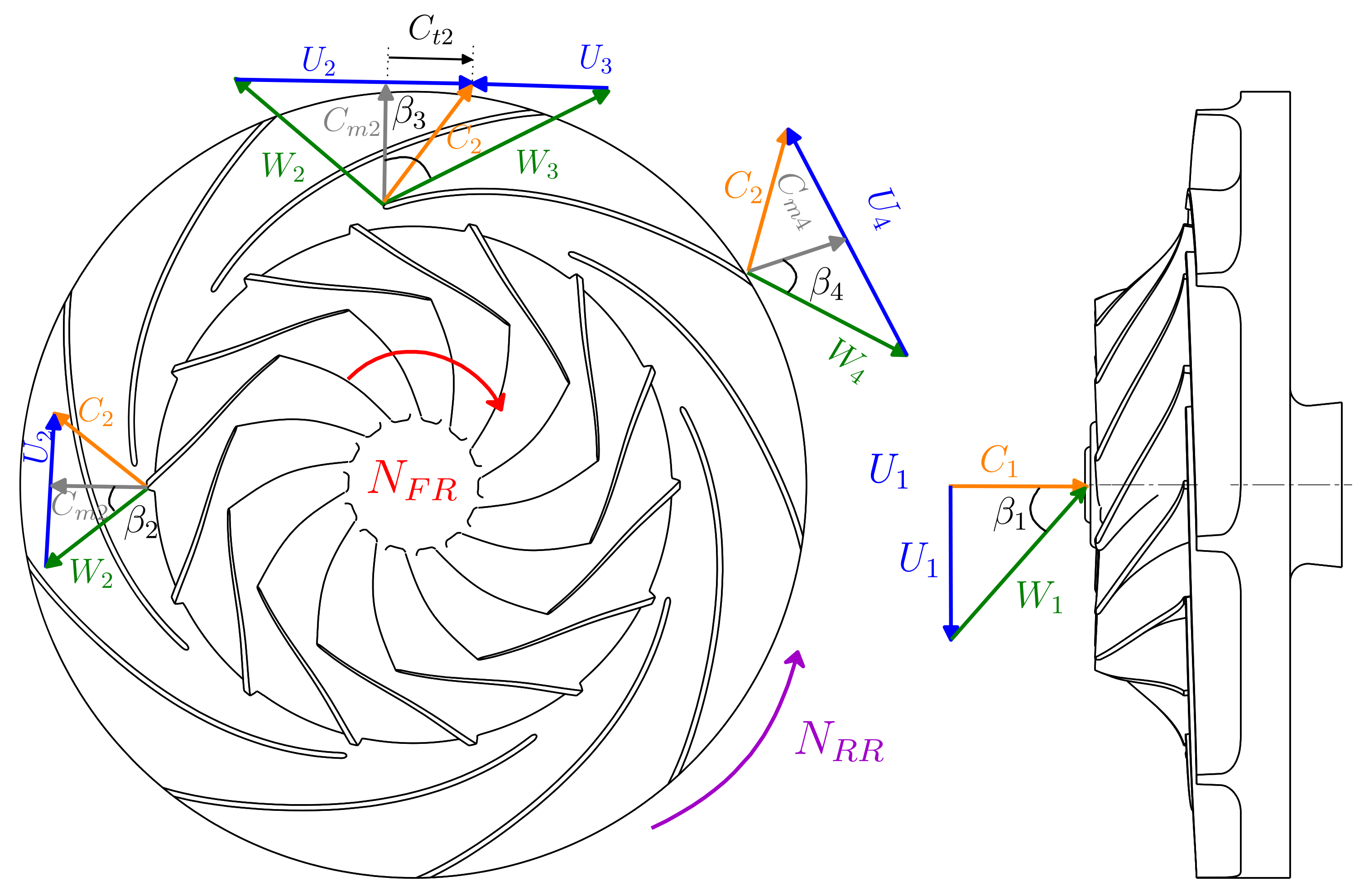
3.1. Velocity Triangles
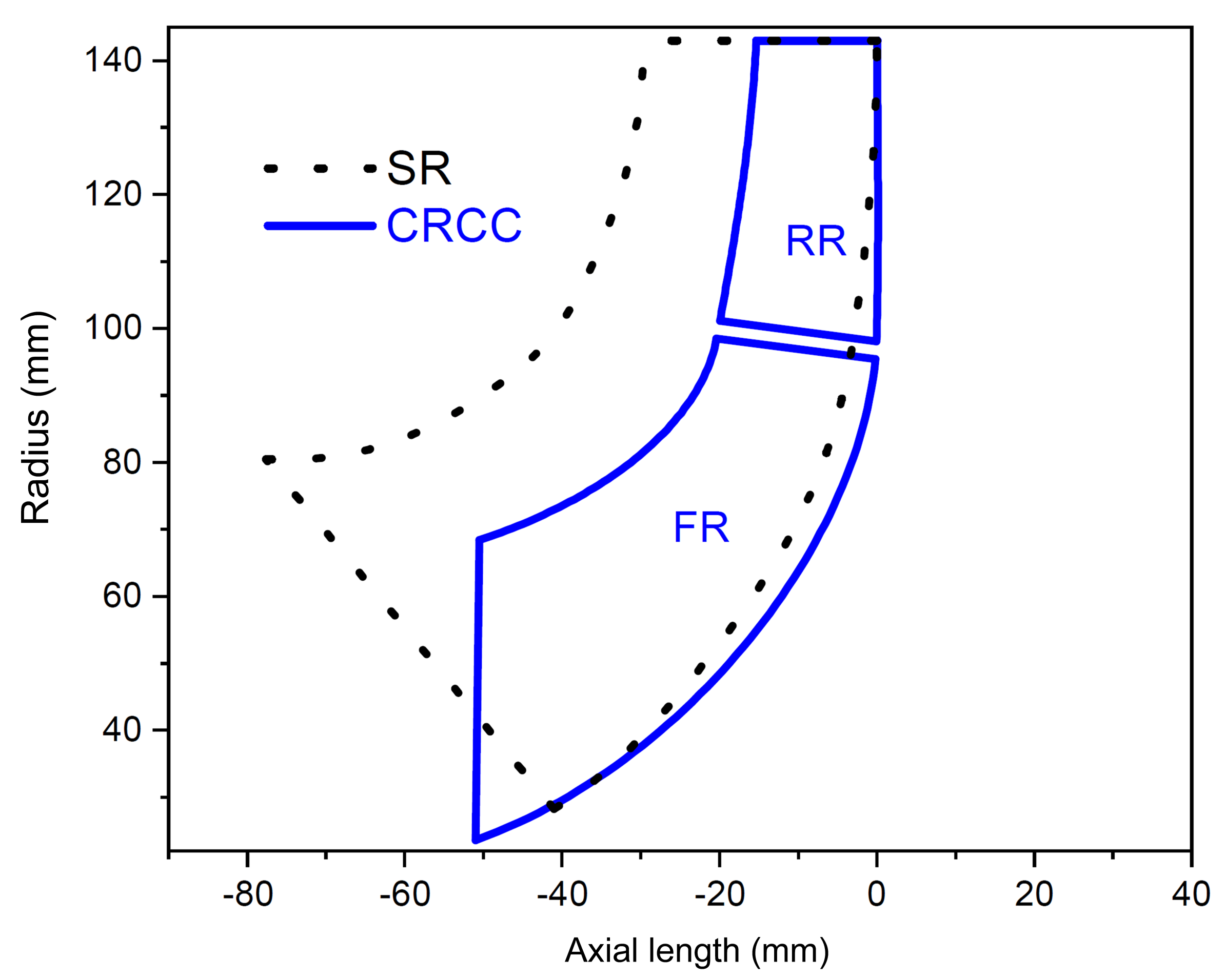
3.2. Comparison between CRCC and SR Layout
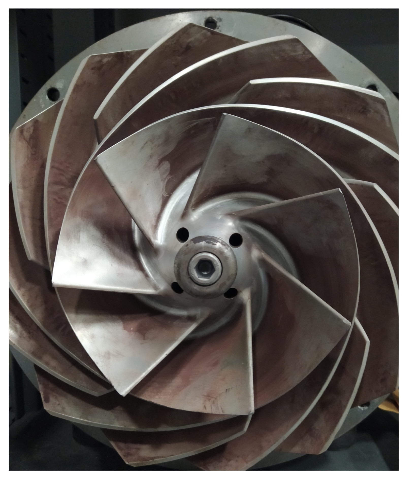
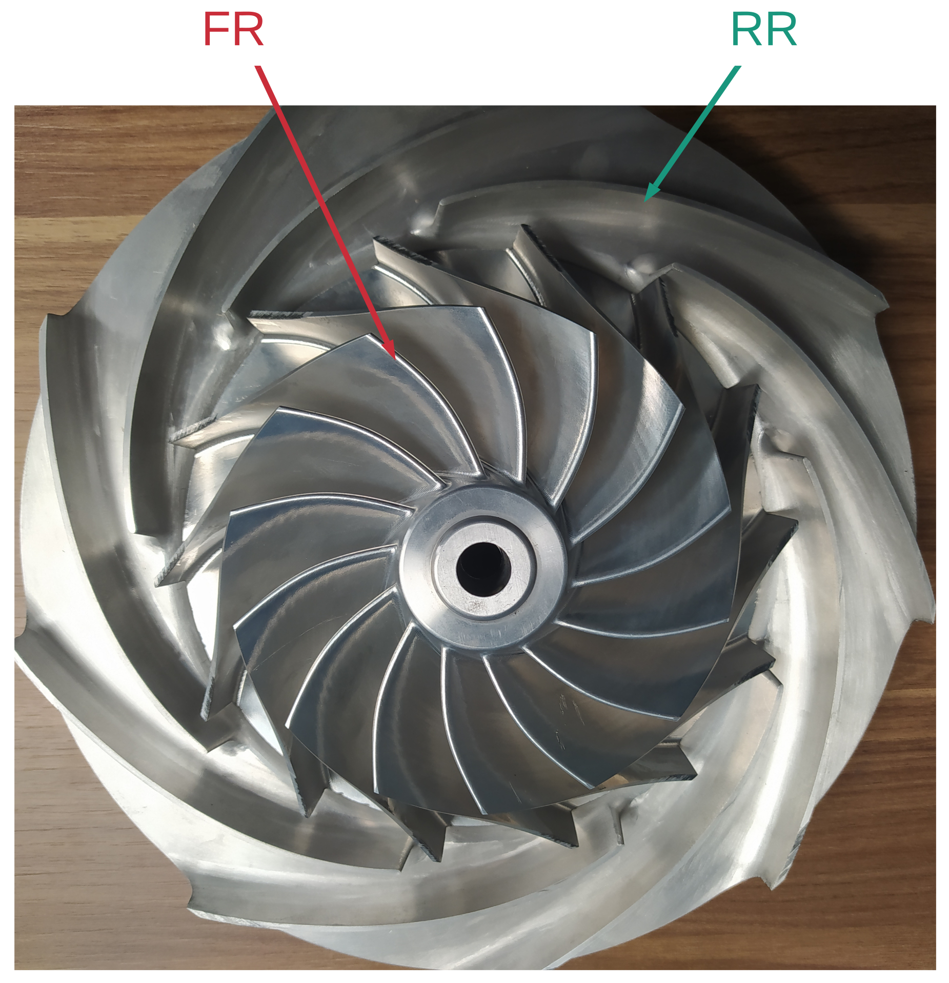
3.3. The Obtained FR and RR Impellers of CRCC
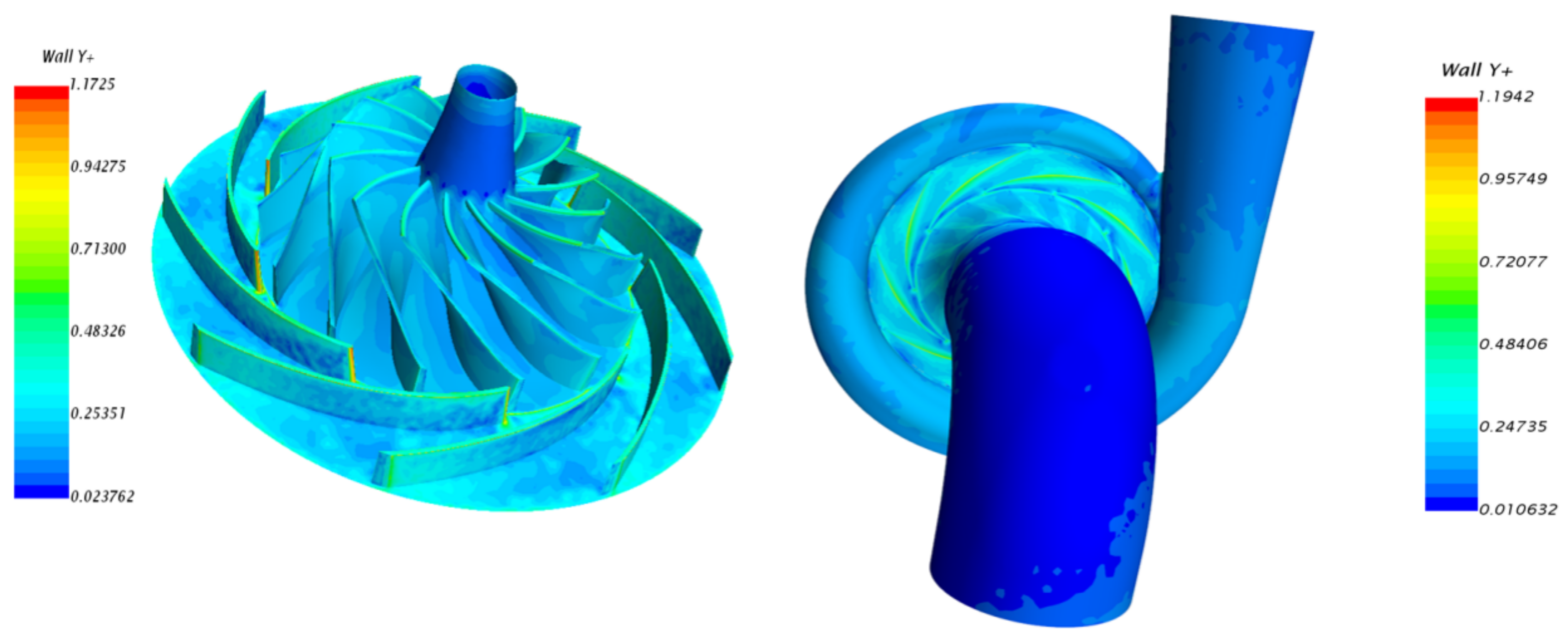
4. Numerical Method
5. Experimental Setup
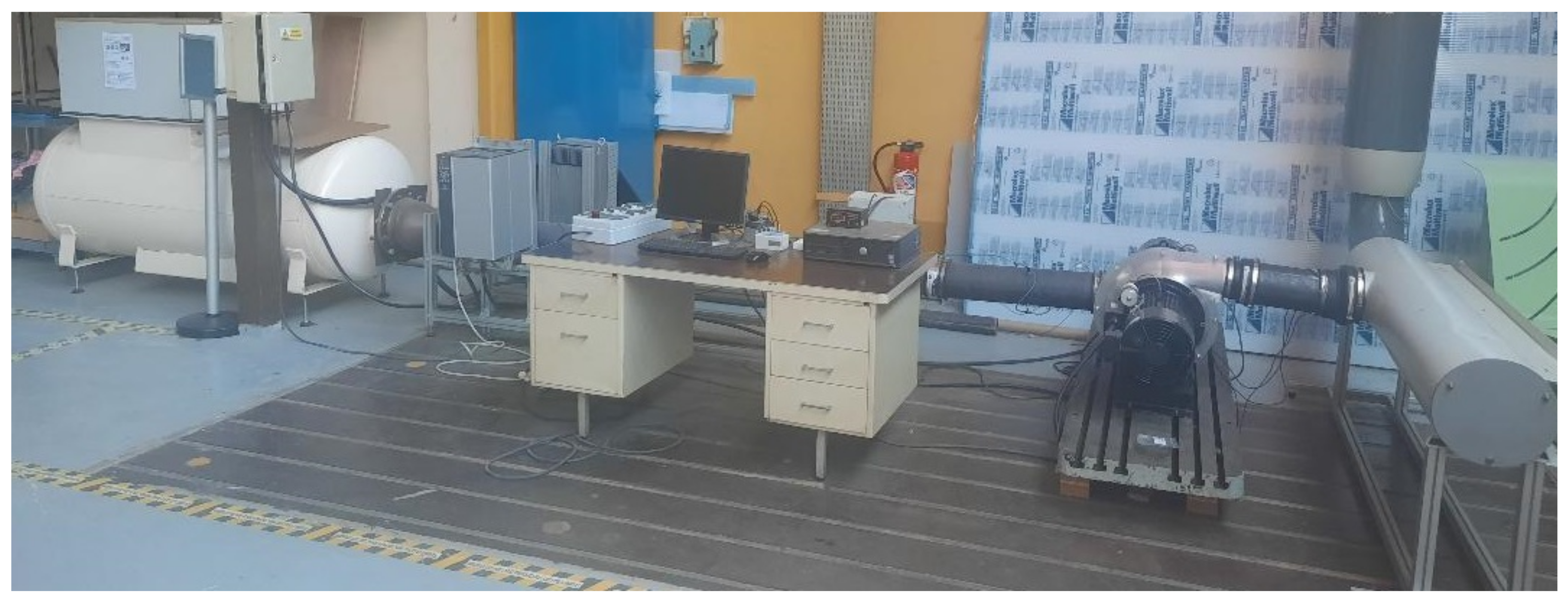
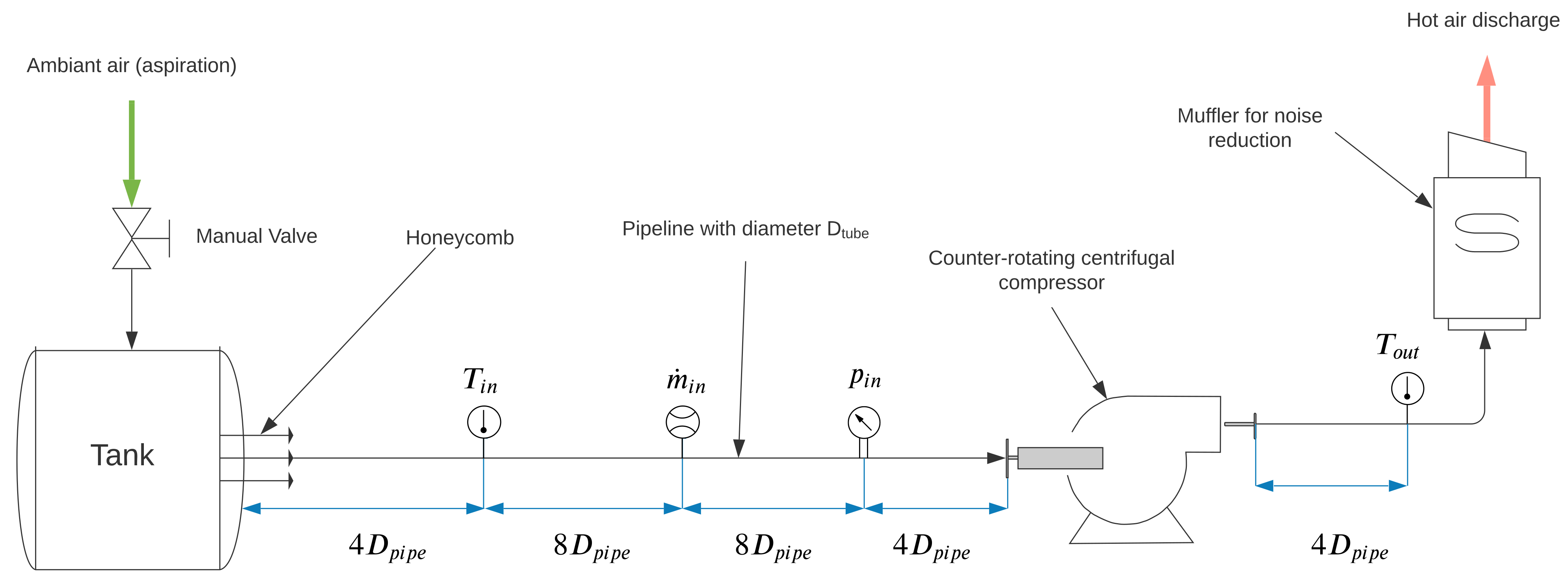
5.1. Description of the Test Rig
5.2. Measurement Method
6. Results and Validation
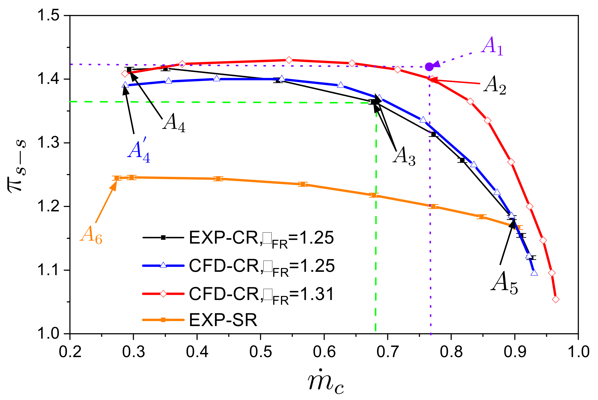
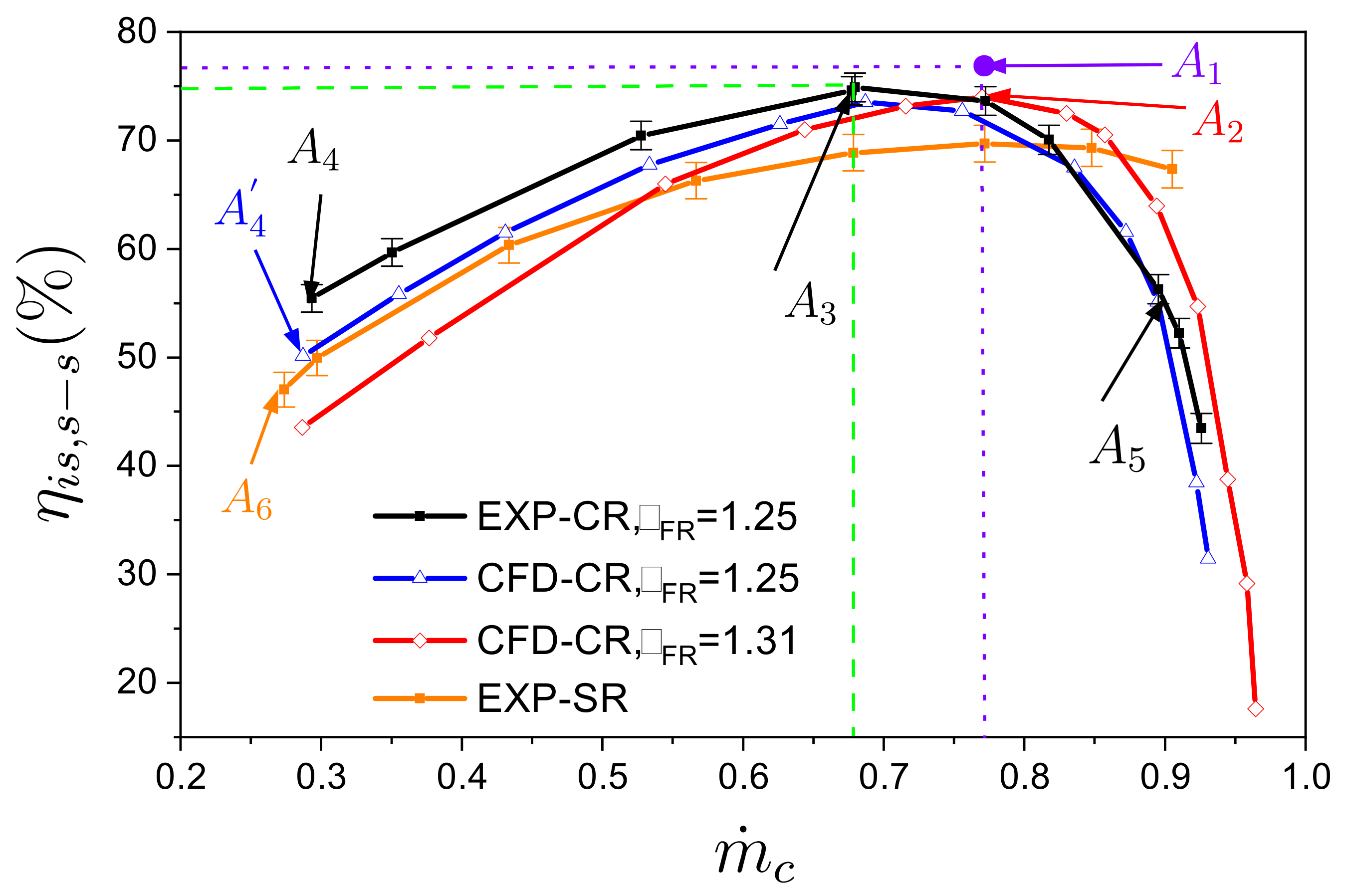
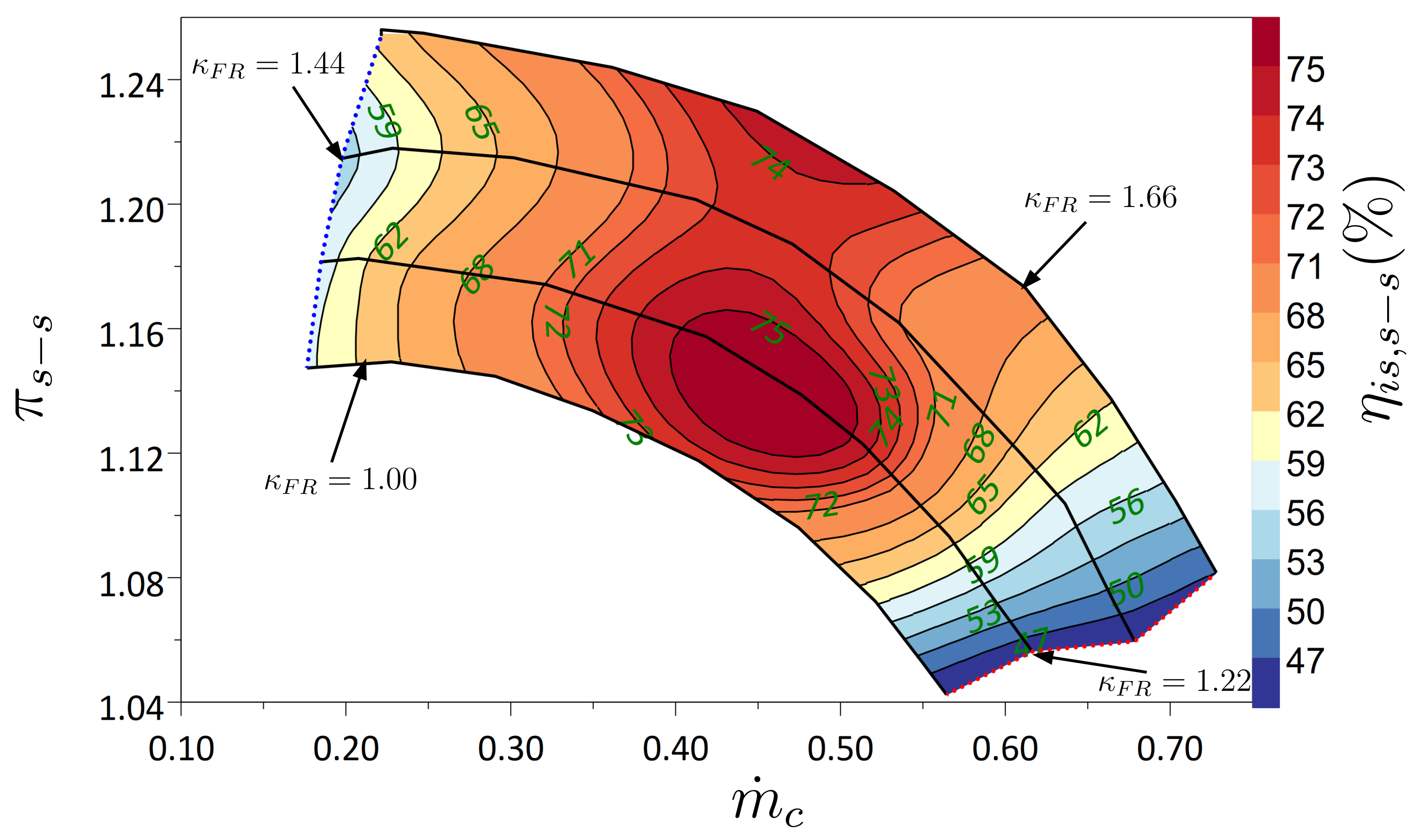
- The second simulation was performed at design conditions: = 17 kRPM and = 13 kRPM. The numerical results show that the pressure ratio given by CFD is also in good agreement with the design point with a small difference. Also, there is a difference of 4 points of isentropic efficiency between the target design with an adapted volute (point ) and the one with the SR volute (point ).
7. Conclusions
Author Contributions
Funding
Institutional Review Board Statement
Informed Consent Statement
Data Availability Statement
Conflicts of Interest
Abbreviations
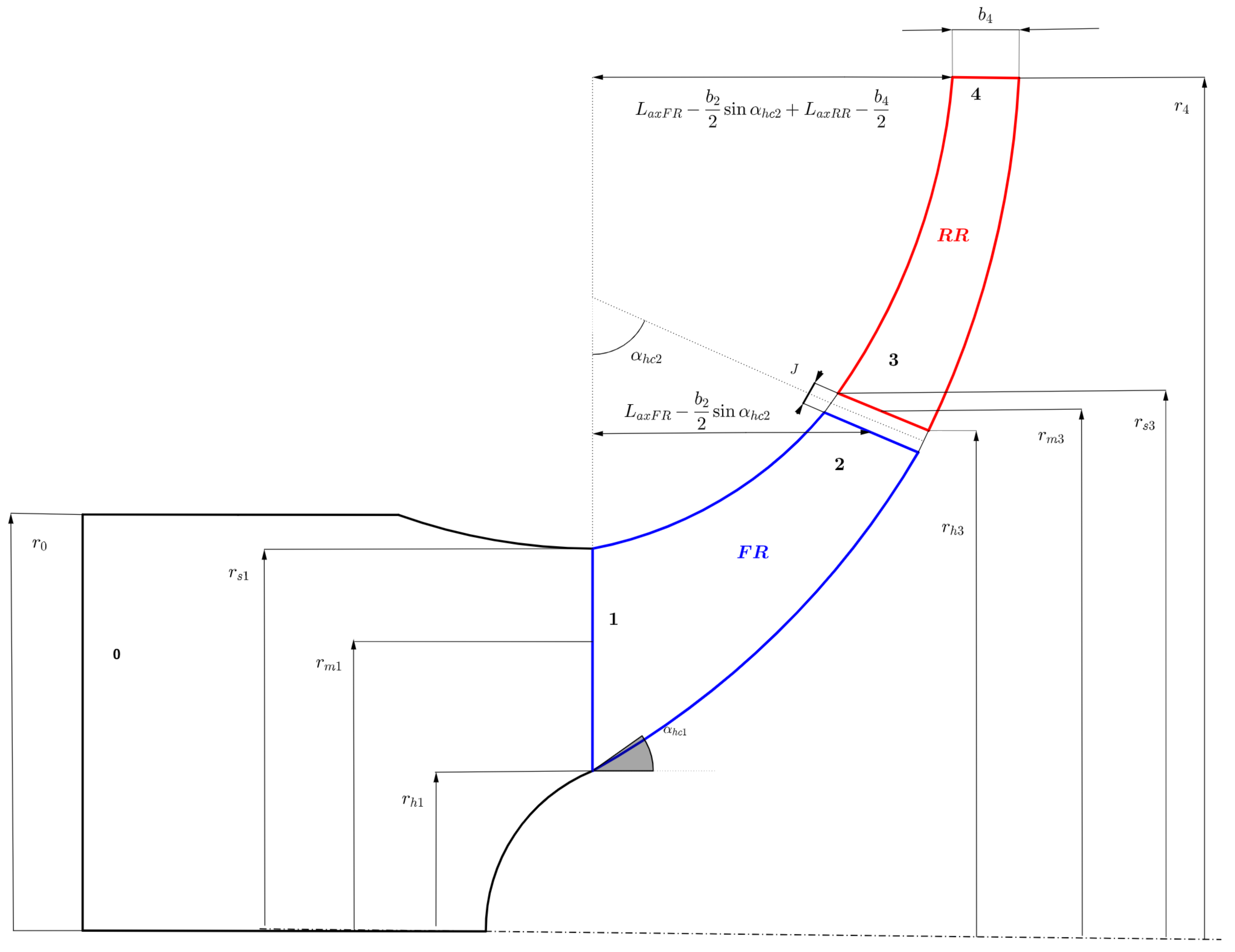
| b | blade width, [m] |
| J | Gap between front and rear impellers, [m] |
| Corrected mass flow rate, [kg·s] | |
| N | Peripheral speed, [RPM] |
| p | Static pressure, [Pa] |
| r | Radius, [m] |
| T | Static temperature, [K] |
| , | Peripheral velocity, [m·s] |
| C | Absolute velocity, [m·s] |
| Tangentiel component of the absolute velocity, [m·s] | |
| Meridional component of the absolute velocity, [m·s] | |
| W | Relative velocity, [m·s] |
| Tangentiel component of the relative velocity, [m·s] | |
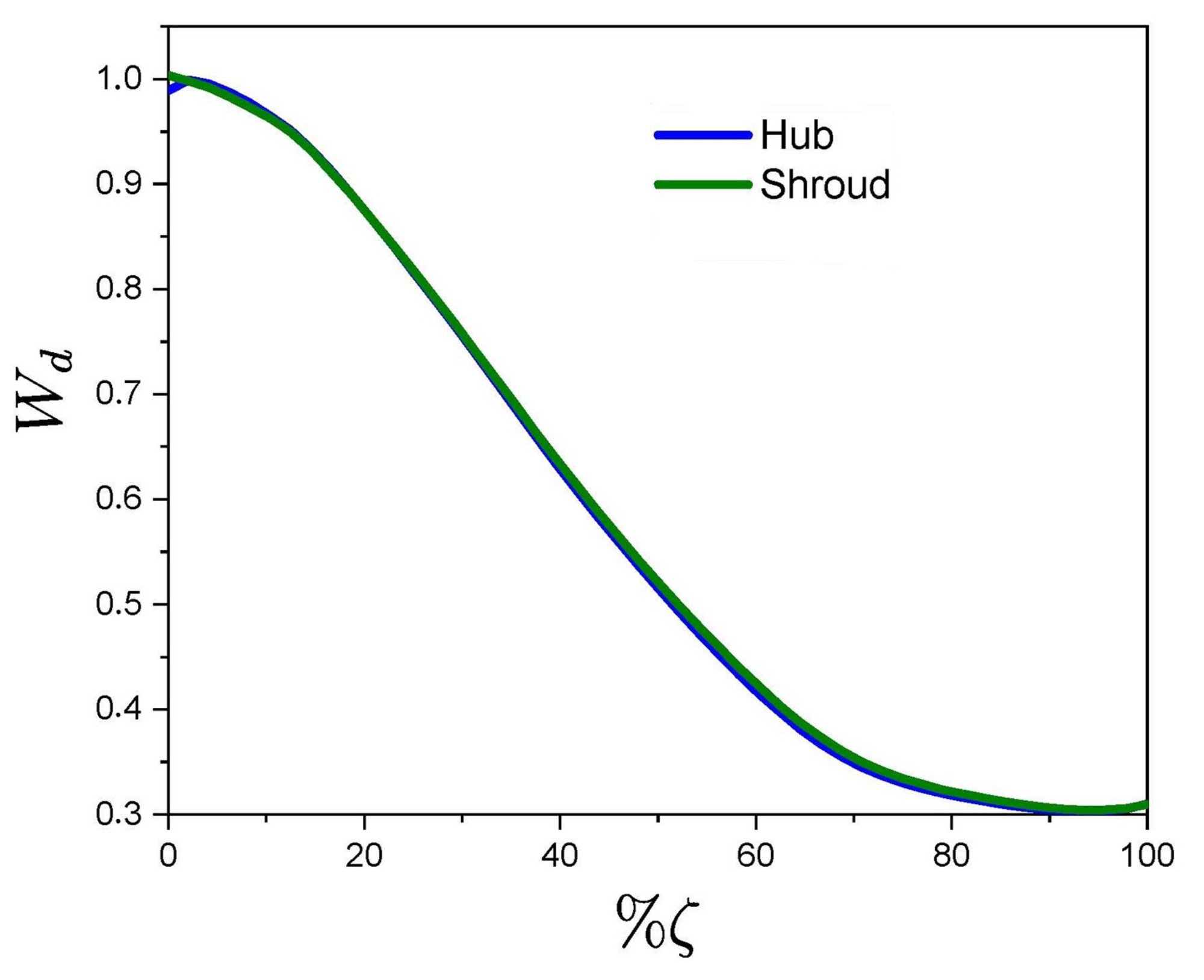
| Dimensionless relative velocity, [-] | |
| Blade angle, [] | |
| Slope angle, [] | |
| Total enthalpy rise, [J·kg] | |
| Pressure rise coefficient, [-] | |
| Static to static isentropic efficiency, [-] | |
| Static to static pressure ratio, [-] | |
| Static density, [kg·m] | |
| Dimensionless meridional distance, [-] | |
| Impeller blade number, [-] | |
| Speed ratio, [-] | |
| Axial distance, [m] | |
| h | Hub |
| s | Shroud |
| Compressor inlet | |
| Compressor outlet | |
| Counter-rotating | |
| Counter-rotating Centrifugal Compressor | |
| Centrifugal compressor with single impeller | |
| CFD | Computational Fluid Dynamic |
References
- Bourne, J. A Treatise on the Screw Propeller: With Various Suggestions of Improvement; Franklin Classics: Franklin, TN, USA, 1855. [Google Scholar]
- Lesley, E.P. Experiments with a Counter-Propeller; American Institute of Aeronautics and Astronautics: Reston, VA, USA, 1933. [Google Scholar]
- Sharma, P.; Jain, Y.; Jha, N.; Khanna, B. Stalling behaviour of a contra-rotating axial compressor stage. In Proceedings of the 7th International Symposium on Air Breathing Engines, Beijing, China, 2–6 September 1985; pp. 734–740. [Google Scholar]
- Sharma, P.; Jain, Y.; Pundhir, D. A study of some factors affecting the performance of a contra-rotating axial compressor stage. Proc. Inst. Mech. Eng. Part A Power Process. Eng. 1988, 202, 15–21. [Google Scholar] [CrossRef]
- Sharma, P.; Pundhir, D. A study of flow structure in a contra-rotating axial compressor stage. In Proceedings of the 9th International Symposium on Air Breathing Engines, Athens, Greece, 3–8 September 1989; pp. 237–244. [Google Scholar]
- Pundhir, D.; Sharma, P. A Study of aerodynamic performance of a contra rotating axial compressor stage. Def. Sci. J. 1992, 42, 191–199. [Google Scholar] [CrossRef]
- Gao, L.; Li, R.; Miao, F.; Cai, Y. Unsteady Investigation on Tip Flow Field and Rotating Stall in Counter-Rotating Axial Compressor. J. Eng. Gas Turbines Power 2015, 137, 072603. [Google Scholar] [CrossRef]
- Dejour, Q.; Vo, H.D. Assessment of a Novel Non-Axial Counter-Rotating Compressor Concept for Aero-Engines. In Proceedings of the ASME Turbo Expo 2018: Turbomachinery Technical Conference and Exposition, Lillestrøm, Norway, 11–15 June 2018. [Google Scholar]
- Nouri, H.; Ravelet, F.; Bakir, F.; Sarraf, C.; Rey, R. Design and Experimental Validation of a Ducted Counter-Rotating Axial-Flow Fans System. J. Fluids Eng. 2012, 134, 104504. [Google Scholar] [CrossRef]
- Nouri, H.; Danlos, A.; Ravelet, F.; Bakir, F.; Sarraf, C. Experimental Study of the Instationary Flow Between Two Ducted Counter-Rotating Rotors. J. Eng. Gas Turbines Power 2013, 135, 022601. [Google Scholar] [CrossRef]
- Wang, J.; Ravelet, F.; Bakir, F. Performance gains provided by the use of a counter-rotating axial-flow fan with respect to a conventional rotor-stator stage. J. Energy Power Sources 2015, 2, 9. [Google Scholar]
- Ravelet, F.; Bakir, F.; Sarraf, C.; Wang, J. Experimental investigation on the effect of load distribution on the performances of a counter-rotating axial-flow fan. Exp. Therm. Fluid Sci. 2018, 96, 101–110. [Google Scholar] [CrossRef]
- Cao, L.; Honda, H.; Yoshimura, H.; Watanabe, S.; Furukawa, A. Experimental Investigation of Blade Rows Interactions in Contra-Rotating Axial Flow Pump. Available online: https://asmedigitalcollection.asme.org/FEDSM/proceedings-abstract/FEDSM2014/46223/V01BT10A040/233119 (accessed on 10 January 2021).
- Cao, L.; Watanabe, S.; Furukawa, A.; Wu, D. Numerical Investigation of Influence of Rotor-Rotor Gap on Performances of Contra-Rotating Axial Flow Pump. Available online: https://asmedigitalcollection.asme.org/FEDSM/proceedings-abstract/AJKFluids2015/57212/V001T33A002/227935 (accessed on 10 January 2021).
- Honda, H.; Cao, L.; Watanabe, S.; Tsuda, S.-i.; Furukawa, A. Numerical Investigation on Performance of Contra-Rotating Axial Flow Pump with Different Rear Rotor Design. Available online: https://asmedigitalcollection.asme.org/FEDSM/proceedings-abstract/AJKFluids2015/V01AT33A011/274537 (accessed on 10 January 2021).
- Fukutomi, J.; Shigemitsu, T.; Yasunobu, T. Performance and internal flow of sirocco fan using contra-rotating rotors. J. Therm. Sci. 2008, 17, 35. [Google Scholar] [CrossRef]
- Tosin, S.; Friedrichs, J.; Dreiss, A. Pumping Unit Power-Density Improvement by Application of Counter-Rotating Impellers Design. J. Turbomach. 2016, 138. [Google Scholar] [CrossRef]
- Price, N.C. Counterrotating Supercharger. U.S. Patent 384539A, 21 March 1941. [Google Scholar]
- Christian Friebe, K.H. Centrifugal Compressor with Counter-Rotating Compressor Impellers. D.E. Patent DE102016115710.4A, 24 August 2016. [Google Scholar]
- Kanemoto, T.; Oba, S. Proposition of unique pumping system with counter-rotating mechanism. Int. J. Rotating Mach. 2004, 10, 233–240. [Google Scholar] [CrossRef]
- Ronald, H. Centrifugal Compressors: A Strategy for Aerodynamic Design and Analysis; AMSE Press: New York, NY, USA, 2000. [Google Scholar]
- Asuaje, M.; Bakir, F.; Kouidri, S.; Noguera, R.; Rey, R. Computer-aided design and optimization of centrifugal pumps. Proc. Inst. Mech. Eng. Part J. Power Energy 2005, 219, 187–193. [Google Scholar] [CrossRef]
- Robert, R.; Bakir, F.; Poulain, J. Pompes Rotodynamiques-Similitude et Conception des Pompes Centrifuges; Techniques de l’Ingénieur: Saint-Denis, France, 2012. [Google Scholar]
- Chikh, M.A.A.; Belaidi, I.; Khelladi, S.; Deligant, M.; Bakir, F. Efficiency of bio- and socio-inspired optimization algorithms for axial turbomachinery design. Appl. Soft Comput. 2018, 64, 282–306. [Google Scholar] [CrossRef]
- Chikh, M.A.A.; Belaidi, I.; Khelladi, S.; Hamrani, A.; Bakir, F. Coupling of inverse method and cuckoo search algorithm for multiobjective optimization design of an axial flow pump. Proc. Inst. Mech. Eng. Part J. Power Energy 2019, 233, 988–1006. [Google Scholar] [CrossRef]
- Bourabia, L.; Abed, C.B.; Cerdoun, M.; Khalfallah, S.; Deligant, M.; Khelladi, S.; Chettibi, T. Aerodynamic preliminary design optimization of a centrifugal compressor turbocharger based on a one-dimensional mean-line model. Eng. Comput. 2021. [Google Scholar] [CrossRef]
- Balje, O. Turbomachines—A Guide to Design, Selection, and Theory; John Wiley & Sons: Hoboken, NJ, USA, 1981. [Google Scholar]
- Abed, C.B.; Khelladi, S.; Michael, D.; El Marjani, A.; Farid, B. Preliminary study of a centrifugal compressor with counter-rotating impellers: Design and performances study. In Proceedings of the ASME Turbo Expo 2020: Turbine Technical Conference and Exposition, Online, 21–25 September 2020. [Google Scholar]
- Van den Braembussche, R. Thermodynamics and Fluid Mechanics of Turbomachinery; Martinus Nijhoff Publishers: Dordrecht, The Netherlands, 1985; pp. 829–885. [Google Scholar]
- Japikse, D. Centrifugal Compressor Design and Performance; Concepts ETI: Vermont, VT, USA, 1996. [Google Scholar]
- STAR-CCM+, U.G. Version 13.064. 2018. Available online: https://www.plm.automation.siemens.com/global/en/products/simcenter/STAR-CCM.html (accessed on 10 January 2021).
- Menter, F.R.; Kuntz, M.; Langtry, R. Ten years of industrial experience with the SST turbulence model. Turbul. Heat Mass Transf. 2003, 4, 625–632. [Google Scholar]
- Gibson, L.; Galloway, L.; Kim, S.; Spence, S. Assessment of turbulence model predictions for a centrifugal compressor simulation. J. Glob. Power Propuls. Soc. 2017, 1, 142–156. [Google Scholar] [CrossRef]
- Bourgeois, J.A.; Martinuzzi, R.J.; Savory, E.; Zhang, C.; Roberts, D.A. Assessment of turbulence model predictions for an aero-engine centrifugal compressor. J. Turbomach. 2011, 133. [Google Scholar] [CrossRef]
- ISO. Turbocompressors—Performance Test Code—Simplified Acceptance Test; International Organization for Standardization: Vernier, Switzerland, 2016. [Google Scholar]
- Valencia, E.; Granja, V.; Palacios, J.; Poveda, R.; Cando, E.; Hidalgo, V. Uncertainty analysis of a test-rig for centrifugal compressors. Rev. Politécnica 2015, 35, 19. [Google Scholar]









| Parameter | Value |
|---|---|
| 30 mm | |
| 30 mm | |
| 81 mm | |
| 143 | |
| 30 mm | |
| 7/7 | |
| kg·s | |
| 13 kRPM |
| No of Elements (In Millions) | Error of (%) | (%) | Error of (%) | |
|---|---|---|---|---|
| − | − |
| Point | ||||||
|---|---|---|---|---|---|---|
| kg·s | kg·s | − | − | |||
| kg·s | kg·s | − | − | |||
| kg·s | kg·s | |||||
| kg·s | kg·s | − | − | |||
| kg·s | kg·s | − | − | |||
| kg·s | kg·s | |||||
| kg·s | kg·s | − | − |
| Point | ||||
|---|---|---|---|---|
| kg·s | kg·s | |||
| kg·s | kg·s | |||
| kg·s | kg·s | |||
| kg·s | kg·s | |||
| kg·s | kg·s |
| Point | ||||
|---|---|---|---|---|
| kg·s | kg·s | |||
| kg·s | kg·s | |||
| kg·s | kg·s | |||
| kg·s | kg·s | |||
| kg·s | kg·s |
Publisher’s Note: MDPI stays neutral with regard to jurisdictional claims in published maps and institutional affiliations. |
© 2021 by the authors. Licensee MDPI, Basel, Switzerland. This article is an open access article distributed under the terms and conditions of the Creative Commons Attribution (CC BY) license (https://creativecommons.org/licenses/by/4.0/).
Share and Cite
Abed, C.B.; Khelladi, S.; Deligant, M.; El Marjani, A.; Solis, M.; Bakir, F. Experimental Validation of the Aerodynamic Performance of an Innovative Counter-Rotating Centrifugal Compressor. Energies 2021, 14, 2582. https://doi.org/10.3390/en14092582
Abed CB, Khelladi S, Deligant M, El Marjani A, Solis M, Bakir F. Experimental Validation of the Aerodynamic Performance of an Innovative Counter-Rotating Centrifugal Compressor. Energies. 2021; 14(9):2582. https://doi.org/10.3390/en14092582
Chicago/Turabian StyleAbed, Cheikh Brahim, Sofiane Khelladi, Michael Deligant, Abdellatif El Marjani, Moisés Solis, and Farid Bakir. 2021. "Experimental Validation of the Aerodynamic Performance of an Innovative Counter-Rotating Centrifugal Compressor" Energies 14, no. 9: 2582. https://doi.org/10.3390/en14092582
APA StyleAbed, C. B., Khelladi, S., Deligant, M., El Marjani, A., Solis, M., & Bakir, F. (2021). Experimental Validation of the Aerodynamic Performance of an Innovative Counter-Rotating Centrifugal Compressor. Energies, 14(9), 2582. https://doi.org/10.3390/en14092582


