Article

Experimental Evaluation and Modeling of Air Heating in a Ceramic Foam Volumetric Absorber by Effective Parameters

by
Carlos E. Arreola-Ramos
1,
Omar Álvarez-Brito
1,
Juan Daniel Macías
1,
Aldo Javier Guadarrama-Mendoza
1,
Manuel A. Ramírez-Cabrera
1,
Armando Rojas-Morin
2,
Patricio J. Valadés-Pelayo
1,
Heidi Isabel Villafán-Vidales
1,3 and
Camilo A. Arancibia-Bulnes
1,*
1
Instituto de Energías Renovables, Universidad Nacional Autónoma de México, Morelos 62580, Mexico
2
Depto. de Termofluidos, Facultad de Ingeniería, Universidad Nacional Autónoma de México, Ciudad de México 04510, Mexico
3
Department of Chemical Engineering, University of the Basque Country UPV/EHU, P.O. Box 644, E48080 Bilbao, Spain
*
Author to whom correspondence should be addressed.
Energies 2021, 14(9), 2506; https://doi.org/10.3390/en14092506
Submission received: 15 March 2021 / Revised: 8 April 2021 / Accepted: 12 April 2021 / Published: 27 April 2021
(This article belongs to the Section A5: Hydrogen Energy)

Abstract

:
Reticulate porous ceramic reactors use foam-type absorbers in their operation which must fulfill two essential functions: favoring the volumetric effect and increasing the mass and heat transfer by acting as a support for the reactive materials. Heating these absorbers with highly inhomogeneous concentrate irradiation induces high thermal gradients that affect their thermal performance. Owing to the critical function of these component in the reactor, it is necessary to define a selection criterion for the foam-type absorbers. In this work, we performed an experimental and numerical thermal analysis of three partially stabilized zirconia (PSZ) foam-type absorbers with pore density of 10, 20, and 30 PPI (pores per inch) used as a volumetric absorber. A numerical model and an analytical approximation were developed to reproduce experimental results, and calculate the thermal conductivity, as well as volumetric heat transfer coefficient. The results show that an increase in pore density leads to an increase in the temperature difference between the irradiated face and the rear face of the absorber, this occurs because when pore density increases the concentrated energy no longer penetrates in the deepest space of the absorber and energy is absorbed in areas close to the surface; therefore, temperature gradients are created within the porous medium. The opposite effect occurs when the airflow rate increases; the temperature gradient between the irradiated face and the rear face is reduced. This behavior is more noticeable at low pore densities, but at high pore densities, the effect is less relevant because the internal structure of porous absorbers with high pore density is more complex, which offers obstructions or physical barriers to airflow and thermal barriers to heat transfer. When the steady state is reached, the temperature difference between the two faces of the absorber remains constant if the concentrate irradiation changes slightly, even changing the airflow rate. The results obtained in this work allow us to establish a selection criterion for porous absorbers that operate within solar reactors; this criterion is based on knowledge of the physical properties of the porous absorber, the environment, the working conditions, and the results expected.

1. Introduction

The drawbacks of direct water thermolysis to obtain hydrogen prompted the investigation of thermochemical cycles to produce solar fuels. The study of these cycles began in the early 1960s with a project called Energy Depot [1]. The first proposed cycles consisted of several steps, which became very complicated for practical solar applications [2]. An alternative arose from developing two-step cycles, which became more straightforward and more efficient [3]. Various reactors’ configurations were developed to operate the thermochemical cycle using concentrated solar radiation as an energy source. These so-called solar reactors are commonly categorized based on how they interact with redox material [4] and solar radiation [5] and various reactors’ configurations were developed to operate using concentrated solar radiation as an energy source [6,7,8]. This work considers a cavity reactor [9], with a foam-type absorber standing out for its simplicity and robustness due to the lack of mobile components. The redox material is supported on a porous ceramic structure, acting as a volumetric absorber [10]. The absorber is of great importance, as it provides a high surface area per unit volume [11], favoring mass transfer between the solid redox material and the reactive gas. Foam-type absorbers have shown promising results in absorbing concentrated solar radiation and yielding adequate temperature distribution in their structure [12,13]. Moreover, they stand out for having a much lower cost than honeycomb structures based on silicon carbide (Si–SiC and SiC) and superior resistance to high temperatures, thermal shocks, and chemical corrosion [14,15,16,17]. These absorbers have also been considered in solar tower power plants for heating gases as working fluid in a thermodynamic cycle [18,19]. This application demands receivers to be subject to high irradiance levels, good internal convection, mechanical durability, and low cost. Reported studies of these systems include experimental thermal tests, analytical and numerical heat transfer models [20,21,22,23,24]. Analysis has generally focused on determining the thermal efficiency achieved and the high absorption of radiation on passing through the porous absorber structure [25,26,27,28]. To date, different configurations of reactors have been proposed, where different types of porous absorber structure have been tested [14,15,29]. Thermal tests included temperature measurements in different depths in the absorber. The results showed temperature gradients in different zones, and adjustments were made to improve the temperature profiles. The effect of inhomogeneous illumination of highly concentrated solar radiation on the surface of a porous absorber has already been reported by Roeb M. et al. [16] in a reactor developed in the German Aerospace Center (DLR) and operated in the Cologne solar furnace. In this reactor, the porous absorber consisted of a honeycomb structure (SiC) and it was illuminated with concentrated solar radiation with Gaussian-shaped flux distribution; the authors report a radial temperature gradient at the front face of the absorber, and this temperature gradient is transmitted towards the backside of the monolith absorber. The authors conclude that absorbed radiation’s inhomogeneity and other thermal losses cause a decreasing initial hydrogen production rate. Results have been reported of tests in solar thermochemical reactors with MPSZ (MgO—partially stabilized zirconia) absorbers covered with CeO2 layers (CeO2/MPSZ) [17] and good rates of hydrogen production were obtained. From the thermal point of view, the absorber was instrumented to measure temperatures at the center of the front and rear sides. It was observed that the front temperature reached values in the range of 1373~1473 K, and the rear side 873~973 K. Such marked differences prevented reaction temperatures along the volume of the absorber. However, despite the importance of knowing the porous absorber’s thermal behavior, only a few studies report the temperature distributions in the material. Most studies assume the absorber’s global temperature corresponds to the measurement of one or two sensors, usually located on the absorber’s front face, and the durability of the absorber’s impregnation method after thermal cycling [30]. Moreover, the porous absorber selection criteria are usually not discussed, nor are the effect of changing porosity and gas flow rates. Recently, V.R. Patil et al. [31] performed an experimental analysis of several reticulated porous ceramic (RPC) absorbers with different porosities and RPC materials (silicon-infused silicon carbide, alumina, and ceria). The RPCs were exposed to various concentrated solar radiation ratios and airflow rates in order to determine the thermal efficiency and air outlet temperature. The main conclusions of this work indicate that larger pores size enhance heat transfer while variable porosity across the RPC absorber reduce temperature gradients. Also, the authors deduce that higher airflow rates increase heat transfer between the fluid and the solid. The highest experimental thermal efficiency was achieved with a Si–SiC (silicon-infused silicon carbide) RPC absorber with 10 PPI (pores per inch). The authors highlight the importance of convective heat exchange together with volumetric radiation absorption to achieve the volumetric effect [32]. Finally, the authors suggest that incident concentrated radiation penetrates the RPC and undergoes attenuation. The effective transport properties and thermal performance of different RPC absorbers exposed to high solar concentration ratios are usually investigated with simulation techniques that use ideal porous structures [33] or through experiments under highly controlled conditions such as constant radiative flux or temperature [34]. Either way, the goal of both techniques is to obtain the thermal and performance parameters to be applied in real operating conditions. The correct selection of these semi-empirical parameters is a very important issue in the homogeneous equivalent models [18]. Perfect knowledge of these parameters is critical when RPC absorbers are exposed to high solar concentration ratios. Porous absorber selection criteria is a difficult subject to approach due to it requiring a deep knowledge of the physical properties of the porous absorber the environment, and the working conditions where it will operate [35,36,37]. Absorbers selected must be capable of operating minimizing heat losses and favoring heat and mass transfer between the reactants. Furthermore, porous absorbers must have a long effective area to host the reactants [38]. In this work, we performed an experimental and numerical thermal analysis of three Partially Stabilized Zirconia (PSZ) foam-type absorbers with a pore density of 10, 20, and 30 PPI used as a volumetric absorber. A numerical model and an analytical approximation were developed to reproduce experimental results and calculate the thermal conductivity, as well as volumetric heat transfer coefficient. Values obtained for the volumetric heat transfer coefficient were 308 and 971 Wm−3K−1, for the 10 and 30 L/min−1 in airflow, respectively; while the thermal conductivity values calculated were 1.4, 0.52, and 0.3 Wm−1K−1 for the 10 PPI, 20 PPI, and 30 PPI absorbers, respectively. The results obtained in this work allow us to establish a selection criterion for porous absorbers that operate within solar reactors and, according to the results described above, we have found that the porous absorber with a pore density of 20 PPI is the most suitable to operate inside the reactor since its properties will favor the volumetric effect and mass and heat transfer inside the absorber.

2. Materials and Methods

2.1. Volumetric Absorber and Solar Reactor

The volumetric absorbers used to carry out the experimental tests were PSZ Zirconia foam filters (partially stabilized zirconia, from Apogee Ceramics Inc. Brantford Ontario, Canada) with pore density: 10, 20, 30 PPI ± 2 PPI, porosity: 80–90%, and bulk density: 0.7–0.85 g·cm−3. This foam-type ceramic was selected owing to its properties of high thermal shock resistance, low reactivity, high effective surface area, standardized pore sizes, and excellent high-temperature creep resistance. The selected absorbers were: 10, 20, and 30 PPI (Figure 1).
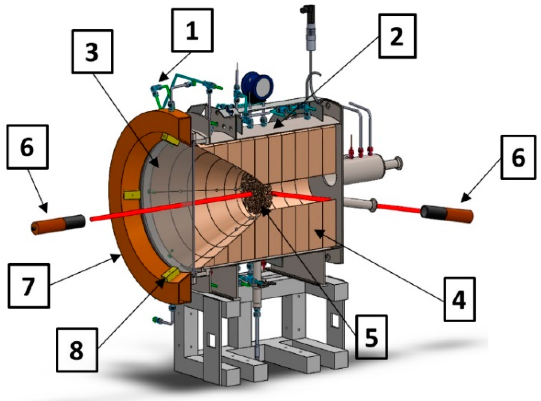
The volumetric absorbers were placed inside a specially designed solar reactor (Figure 2). The reactor has an outer body made of AISI (American Iron and Steel Institute) 304 stainless steel, with multiple ports for electronic instrumentation (30 thermocouples and 2 pressure sensors), a removable back cover to allow access to the reaction chamber without manipulating the glass window, and there is a rear port for pyrometric temperature sensing. The reaction chamber is made of ring-shaped alumina thermal insulator arrays, formed to a conical shape at the entrance of the reactor. Ring-shaped ceramic supports are placed concentrically inside the reaction chamber, allowing swapping absorbers during tests. The reactor glass window consists of a tempered flat glass plate with 450 mm in diameter and 6.35 mm in thickness. This window has a water-cooled circular aperture stop to limit the heating of sensitive parts of the system due to the incoming radiation. Also, four external air nozzles are used to cool-down the window. This combination of an air-cooled glass window with a water-cooled stop avoids thermal stress-related breakages. The glass window is located 260 mm from the hot surface of the volumetric absorber, this fact prevents the window from overheating. The gas (air in the present study) is introduced into the reaction chamber through four nozzles, which are located behind the window, on the conical walls of the insulator, pointing towards the porous surface.

2.2. Instrumentation and Operation

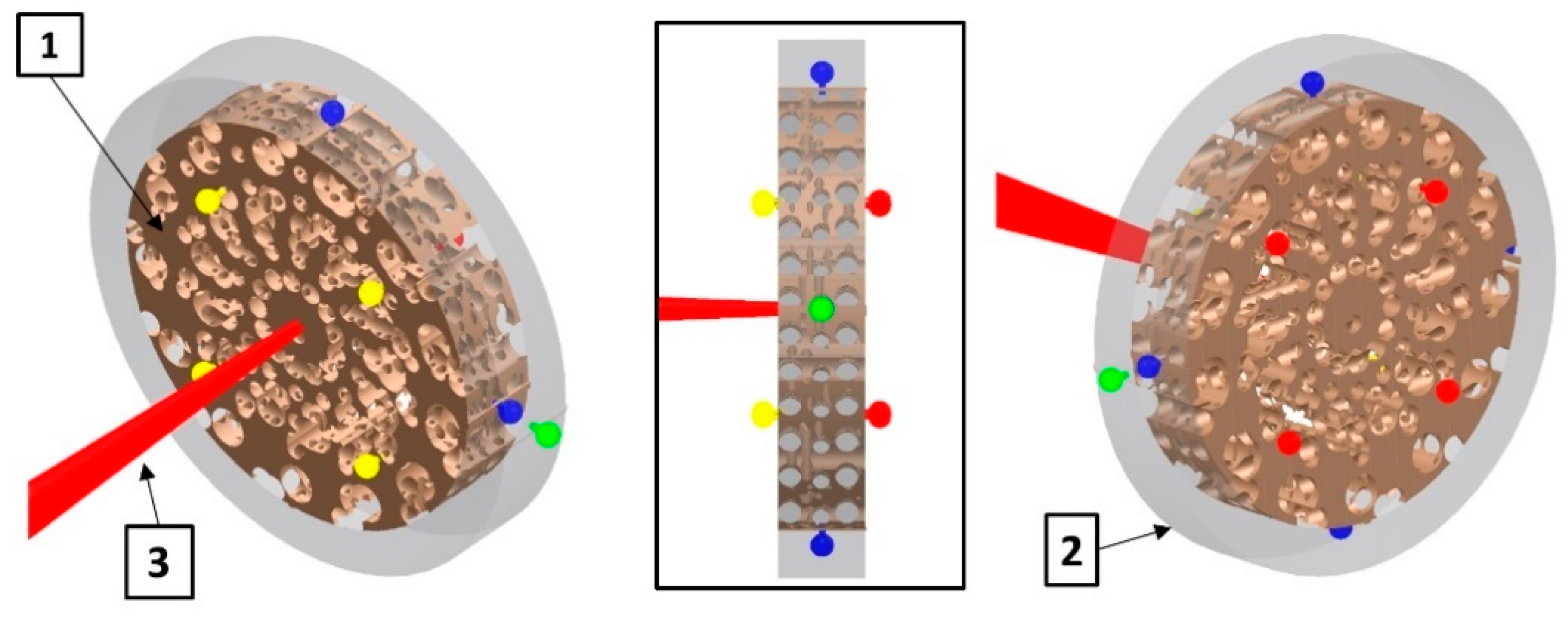
The solar reactor was operated in the IER-UNAM (Instituto de Energías Renovables-Universidad Nacional Autónoma de México) high radiative flux solar furnace (HoSIER) located in Temixco, Morelos, Mexico. The HoSIER operates at a maximum power of 25 kWth (Thermal kW), and its characteristics have been described in the literature [39,40]. The reactor is located so that the material’s illuminated surface is 40 mm behind the solar concentrator’s focal plane. This fact guarantees a uniformity illumination over the absorber’s surface. The absorber thermal instrumentation was performed with sheathed thermocouples (AEROPAK®, (Okazaki Manufac-turing Company, Kobe city, Japan) mineral-insulated thermocouple) consisting of a thin tube (sheath) made of stainless steel or heat-resistant steel, thermocouple wires enclosed within the tube and an inorganic insulator (MgO) firmly packed around the wires. Figure 3 shows the probe locations: four on the absorber (directly irradiated) front face, four on the rear face, exactly opposing the position of the front thermocouples, four on the circular absorber edge, and one at the insulator-ceramic support interface. A high-temperature ceramic cement (OMEGABOND®, OB-600) protected the thermocouple’s contact area from measurement errors in probes exposed to concentrated radiative energy. An Infrared Thermometer (Impac IGA 140/23 Series, from LumaSense Technologies, Inc., Baleful, Denmark) located in front of the reactor window allowed measuring the temperature within the absorber’s central area. Finally, sheathed thermocouples were installed to measure the flowing gas temperature.
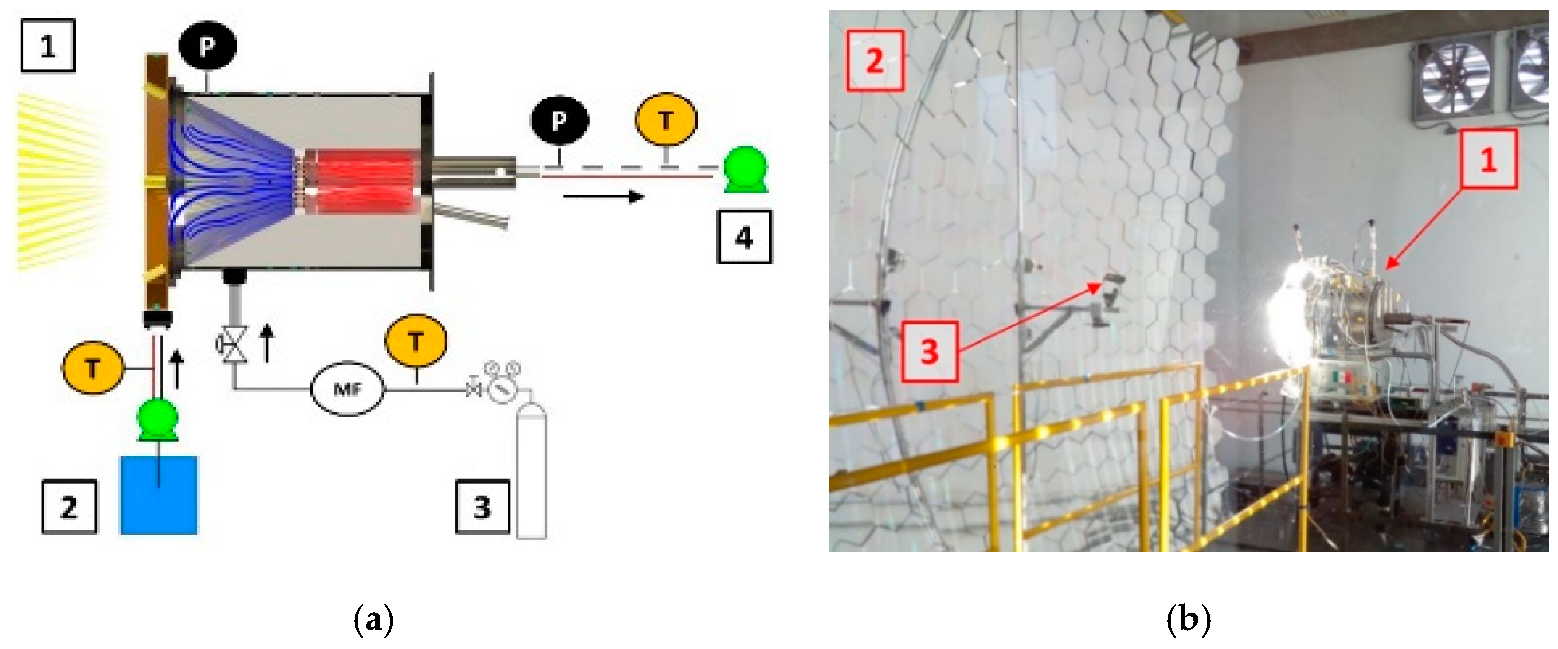
Once the absorber and temperature sensors are installed inside the reactor, the experiments begin with an airflow of 30 L/min−1. The solar furnace’s shutter is opened progressively to avoid thermal shocks by sudden irradiation of the absorber. The front-face thermocouple average reading is stabilized near the target temperature (close to 1110 K in the present study). A steady state is defined when temperature readings change by less than 3% within a timeframe of 5 min. After stabilization at 30 L/min−1, the flow rate is reduced to 10 L/min−1, and the temperature can stabilize again. The procedure is repeated for the three absorber pore densities (10, 20, and 30 PPI), Figure 4 shows the experimental configuration. Temperature and pressure data acquisition was performed with a data logger switch unit (model 34972A LXI, from Keysight Tech-nologies, Colorado Springs, CO, USA). The internal reactor pressure was monitored with a high-quality pressure transmitter (S-20, from WIKA Alexander Wiegand SE & Co., Klingenberg, Germany), with a two-second sampling interval, and followed in real-time through a graphical user interface (GUI).

2.3. Numerical Methods

Heat transfer in the volumetric absorber was modeled in COMSOL MULTIPHYSICS® software version 5.2 (COMSOL, Inc., Burlington, MA, USA). This simulation was carried out to investigate the thermal fields present in the porous absorber from the experimental temperature measurements (thermocouples distributed according to Figure 3). The problem was addressed firstly considering the heat transfer conductivity coefficient non-dependent of temperature by solving the steady-state heat conduction equation:
  ·   k t T   = 0 ,
where the considered thermal conductivity k t is a lumped quantity including the conduction, radiation, and convection heat transfer processes occurring in the porous absorber and is taken as a free parameter. The simulation uses boundary conditions approximately representing the real conditions of the experiment. Considering the cylindrical edge of the porous absorber an adiabatic media:
n ^   ·   q r = r p = k t T r r = r p = 0 ,
here n ^ stands for the unit vector normal to the surface, and q is the heat flux vector. The condition in the flat boundary facing the back of the cavity involves radiation losses:
n ^   ·   q y = L = k t T y y = L = ε σ S B T 4 T cav 4 y = L   ,
where ε is the absorber emissivity,   σ S B is the Stefan–Boltzmann constant (5.67 × 10⁻⁸ Wm−2K−4), and T cav is the cavity temperature. The front surface of the absorber receives and loses energy in the form of radiation, which is represented by the boundary condition in the following equation:
n ^   ·   q y = 0 = k t T y y = 0 = q 0 ε σ S B T 4 T amb 4 ,
where T amb   is the ambient temperature and q 0 is the concentrated solar irradiance. The solar irradiance is not given as a single value but as a discretized 2D distribution based on the experiments’ CCD (Charged Coupled Device) camera images. The receiver surface was covered by 100 pixels of these images.
Many simulation runs were executed by varying the value of the unknown thermal conductivity k t to fit the experimental temperature data obtained from the different thermocouples distributed in the absorber body.

2.4. Analytical Approximation

To evaluate the volumetric heat transfer coefficient [41] inside the porous absorber and for a better interpretation of the numerical model results, we develop an analytical model. This model differs from the numerical simulation described in Equation (4) in the fact that convection heat transfer is dealt with explicitly, instead of considering it part of a lumped heat transfer coefficient. Within the temperature range in the present work (300 to 1110 K) we have approximated air as an ideal gas and considering the air’s specific heat change to be small in this range. Thus, the heating of the air flowing through the porous absorber can be described by:
m ˙ c p d T g d z = A   h V T m T g ,
where the parameter h V   W   m 3 K 1 is the volumetric heat transfer coefficient inside the porous media, and A   m 2 is the cross-sectional area of the sample material. The coefficient h V is an unknown parameter to be resolve in the problem, which will be obtained from the fit to the experimental data results. In parallel to convective heat transfer, conductive and radiative heat transfer occur within the medium [42]. The equation for this combined heat transfer can be expressed as:
d q e , z d z = h V T m T g ,
here q e , z   is the one-dimensional effective conductive-radiative heat flux through the medium. Fourier’s law can describe this in terms of a temperature-dependent combined effective thermal conductivity k e in the form:
q e , z = k e d T d z     ,
this effective thermal conductivity k e is different from, although related to, the lumped conductivity ( k t ) considered in the preceding section. Effective thermal conductivity can be expressed as the sum of the solid conductive and radiative components:
k e = k s + k r ,
where the solid conductivity k s es related to the heat transfer in the solid porous matrix and radiative conductivity k r is related to the heat transfer by radiation inside the porous space. Both contributions to the effective thermal conductivity have been recently evaluated by Macias et al., 2021 [43] for a similar porous material used in this work. Authors have expressed the solid conductive contribution in terms of Archie’s law [44] as:
k s = k 1 p θ ,
where k is the ordinary conductivity in the solid (non-porous) material, p is the porosity, and θ is Archie’s exponent, this value depends on the pore shape and its probability distribution in the material. The conductivity k for solid ZrO2 can be adjusted from the work of Sun et al. (2013) [45] to:
k T = 2.453 + 13.41 exp T / 300.8 ,
where T is the temperature. The radiative conductivity contribution to the effective conductivity was obtained in terms of Rosseland’s approximation [46] as:
k r = 16   σ S B T 3 3 β R   ,
in this expression σ S B stands for Stefan–Boltzmann constant and β R is known as Rosseland’s mean extinction coefficient [47]. Parameters of porosity, Archie’s exponent and Rosseland’s coefficient for a similar porous material used in this work with 20 PPI are: p = 0.84 , θ = 1.12 , and β R = 858   m 1 [43]. Although the effective conductivity k e has a dependence in temperature in the considered range in this work, for simplicity, a constant averaged value will be considered as a first approximation. Under the above assumptions, the system of equations to be solved is:
d T g d z = 2 r T m T g     ,
d 2 T d z 2 = s 2 T m T g     ,
r = A   h V 2 m ˙ c p     ,                 s = h V k e     .
by approximating r and s coefficients as constant, then the coupled Equations (12) and (13) have analytical solution that can be expressed in terms of the two linearly independent functions: exp 1 2 k + k 2 + s 2   z and exp 1 2 k k 2 + s 2   z .

3. Results

3.1. Experimental

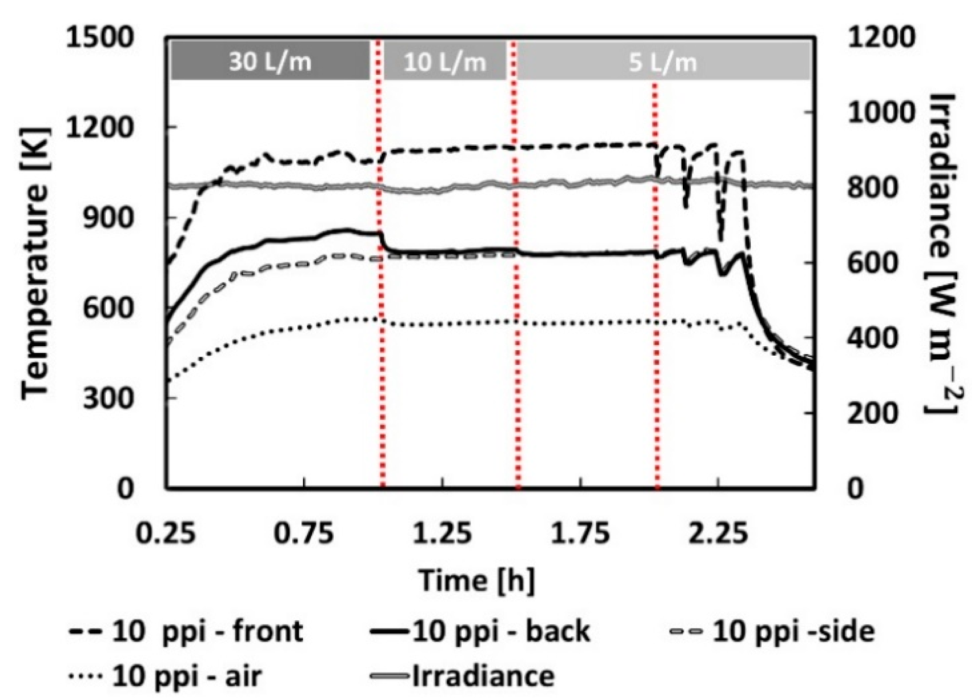
Figure 5 shows the experimental temperature data obtained of the porous absorber with 10 PPI, temperature values correspond to the front and back faces and the porous medium’s edge, in each case, values are an average over the four sensors located in these surfaces (Figure 3). The behavior of this porous absorber is representative of the typical trend of the different porosities studied in this work. The vertical red lines indicate when the flow rate is changed. The most noticeable transient temperature occurs during the first 0.5 h of operation at a flow rate of 30 L/min−1, as can be appreciated in the graph. Nevertheless, the full stabilization required 1.0 h at least. When the steady-state is reached, the temperature difference between the two faces of the absorber is 338 K, this temperature difference remains constant if the solar irradiance is kept at a value close to 800 W m−2, even changing the airflow rate. The experiment continued with the flow rate of 10 L/min−1 for 0.5 h to compensate for minor temperature oscillations due to solar irradiance variations. Then, the flow rate was reduced to 5 L/min−1, and the system was allowed to stabilize again. In the last segment, the flow rate was not changed, but the solar furnace shutter was closed and opened in intervals of 0.4 h, to simulate the system’s response to dispersed clouds. During the shutter’s closures, the absorber’s front face temperature decreased by 110 K, 209 K, and 315 K for the first, second, and third closures. Temperatures presented a delayed response to closures due to the reactor’s large thermal mass.
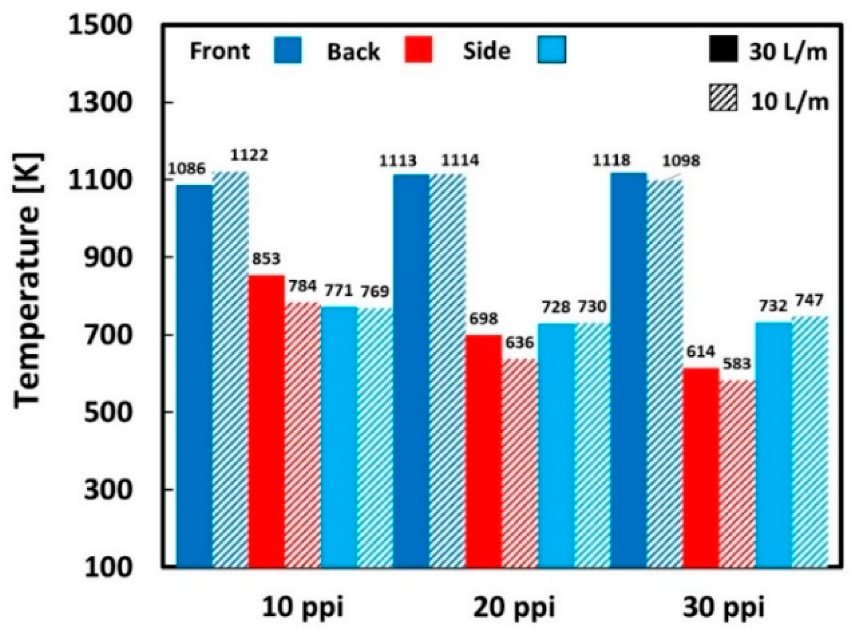
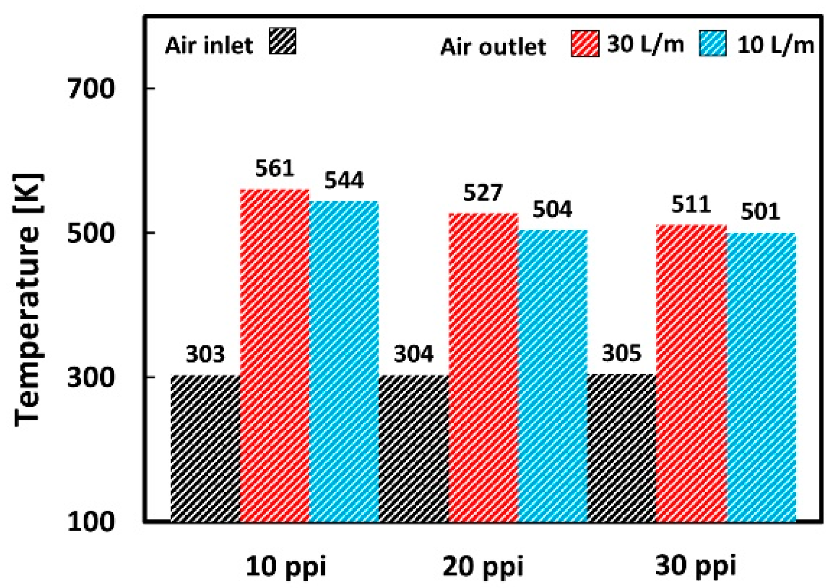
Figure 6 and Figure 7 present the time-averaged temperature measured in the porous absorber and gas (air) for different flow rates’ experimental conditions. The temperature average has also been calculated over the sensors placed in each zone of the porous absorber. The temperature of the front face in the three types of absorber (10, 20, and 30 PPI) does not change in relation to the flowrate or in relation to the pore density because this face is exposed to solar radiation, as expected.
Figure 6 shows a remarkable dependence on the temperature difference between the absorber’s faces and the pore density (PPI) [48]. Considering that pore density is inversely proportional to the pore diameter, thus 10 PPI absorber has the largest pores, and it presents the smallest temperature difference between the front and back face, while the 30 PPI absorber has the smallest pores and the largest ΔT. This behavior can be attributed to the easier passage of the concentrated solar radiation through the largest pores. This higher back face temperature of the porous absorber for larger pore diameters also translates into a higher gas outlet temperature. Regarding the flow rate’s effect, the trend is an increase of both solid (Figure 6) and gas (Figure 7) temperatures in the porous absorber’s back face when this parameter is raised. This increase in the back face temperature with the flow rate is due to more effective heat removal from the material’s hottest parts, reducing losses to the front and transferring heat backward.
Furthermore, Figure 6 shows that changes in flowrate have less effect in ΔT when pore density (PPI) is increased. For example, in the case of the 30 PPI absorber, a slight change is observed in ΔT, even though the flow rate is increased by three times.

3.2. Theoretical

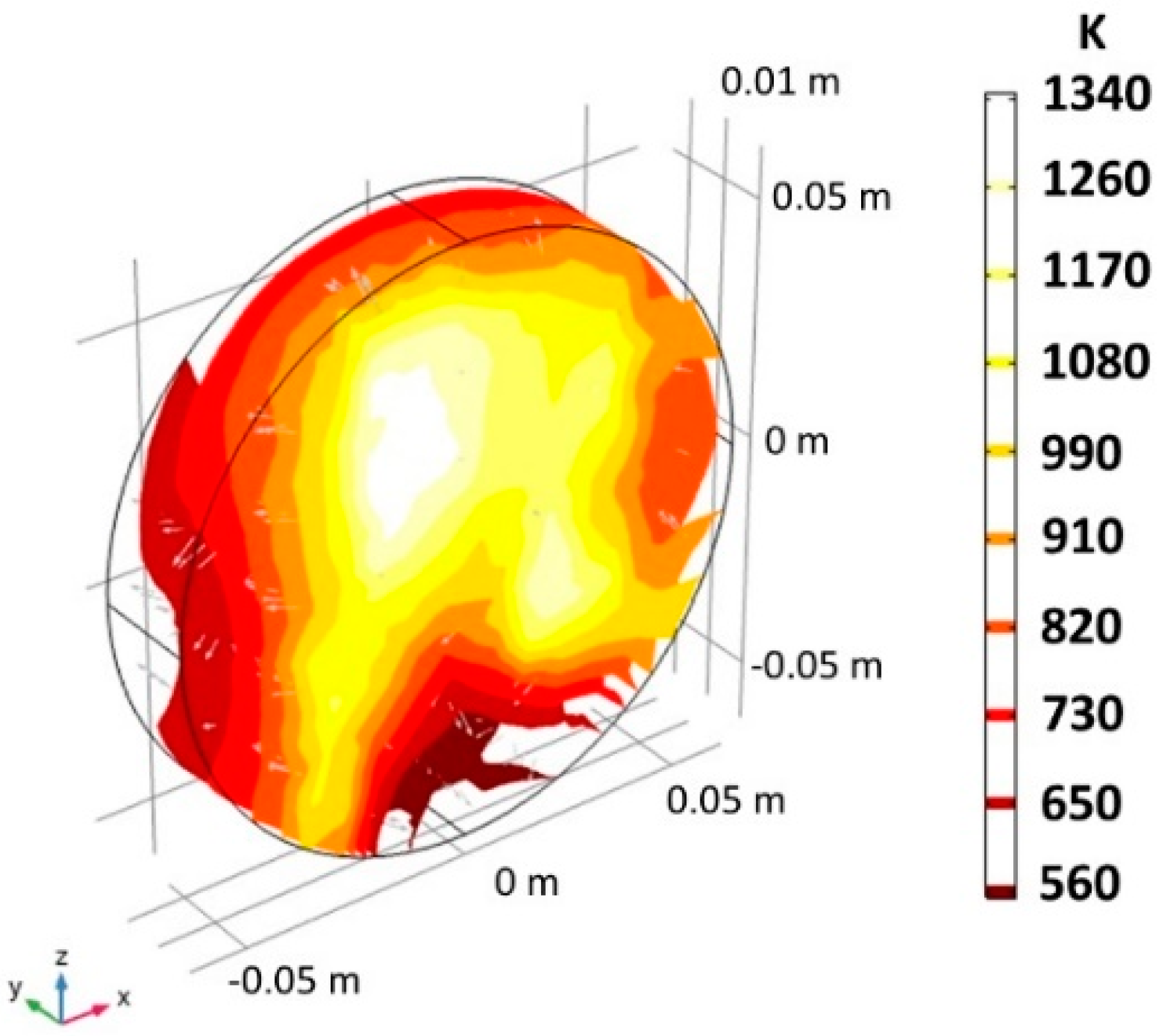
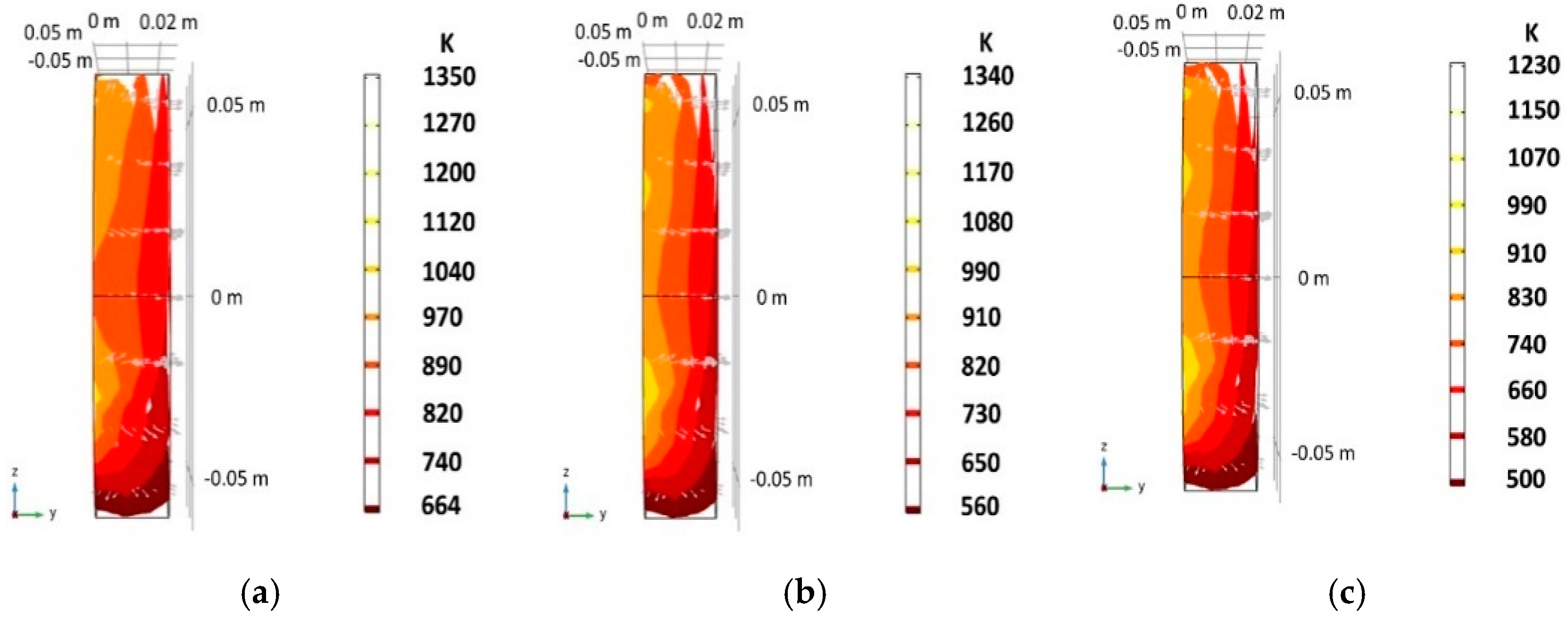
Figure 8 shows the steady-state temperature distribution in the 20 PPI absorber obtained from the numerical simulation with COMSOL. As mentioned previously, the incident radiative flux distribution was included in the numerical simulations’ boundary conditions. The radiative flux irregularities are due to the concentrator optical errors, which are augmented because the solar furnace is operated with the receiver out of focus. Consequently, the radiative flux profiles lead to an irregular and asymmetric temperature distribution. Figure 9 compares the temperature distribution for the different pore densities in the z-y plane (perpendicular to thickness) of the absorber material. It can be observed how the larger pores allow higher temperature values in the inner parts of the material due to the increased radiation penetration. Despite the irregularities, the heat transfer occurs mainly in the z-direction.
Table 1 presents the comparison between experimental and simulated temperature values for different areas in the porous absorber. The simulation simplifies the combined heat transfer by introducing a total conductivity ( k t ). Note that convection and radiation effects induce a preferent directionality in the thermal process producing anisotropy, however this effect is slight in all simulated cases. In this sense, conductivity values in i ^ and k ^ directions gave the best results in the analytical model when they are 98.5% of the conductivity value in the j ^ direction j ^ . This near isotropic behavior is most likely due to the random distribution of the ceramic body’s pores, which internally produce good mixing of the air by forced convection [49]. The simulated total conductivity k t values that best fit the experimental data for absorbers with pore density of 10 PPI, 20 PPI, and 30 PPI were, respectively, 1.4, 0.52, and 0.3 Wm−1K−1. Comparing the RMS of the three absorbers, the absorber with 30 PPI presents the highest deviation, this is since the internal structure of porous absorbers with high pore density is more complex, which offers obstructions or physical barriers to airflow and thermal barriers to heat transfer.
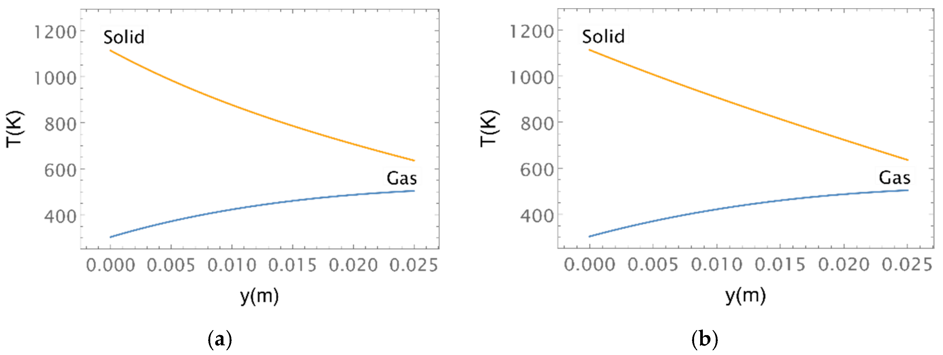
The results of the solution of the analytical model of Equations (12) and (13) are presented in Figure 10. The solid and gas temperatures are depicted for the 20 PPI porosity absorber, for 30 and 10 L/min−1 flowrates. As mentioned above, the absorber’s front and back temperatures and the air inlet temperatures were fixed to the experimental values (Figure 7). Meanwhile, the volumetric heat transfer coefficient h V (Equation (5)) was varied to fit the experimental air outlet temperature data. The fits were accurate to 0.5 K, and the values obtained for h V were 308 and 971 W K−1m−1, for the 10 and 30 L/min−1 cases, respectively.

4. Discussion

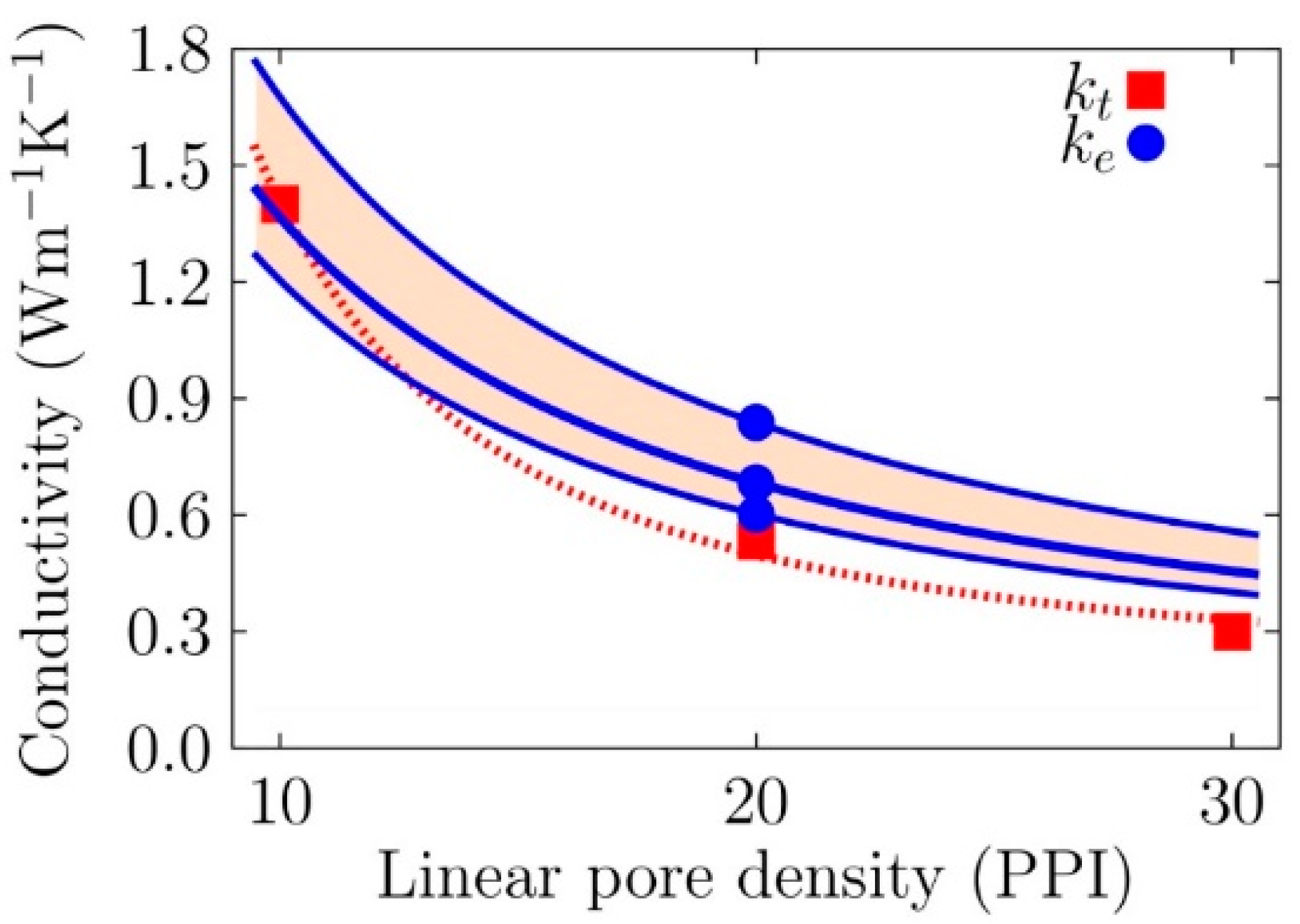
Define the thermal properties of porous media is not an easy task, just as describing the temperature distribution within the porous media is also not trivial. The advantage of the analytical model developed lies in the decoupling of the three heat transfer contributions, which allows assigning a more precise physical meaning to the parameters obtained. With this analytical model is possible to obtain from the experiments an estimation for the volumetric heat transfer coefficient and the thermal conductivity which are hard to determine by other means [50,51,52]. The values obtained for the volumetric heat transfer coefficient were 308 and 971 Wm−3K−1, for 10 and 30 L/min−1 flowrates, which could be compatible with a nearly linear scaling with Reynolds number [53]. The values calculated for thermal conductivity in the absorbers with 10 PPI, 20 PPI, and 30 PPI were, respectively, 1.4, 0.52, and 0.3 Wm−1K−1, and this trend is roughly inverse to pore density [54] (see Figure 11). However, this behavior is not attributable only to solid matrix conduction effects because, for media of the same material and type of geometry, the thermal conductivity depends essentially on the air volume fraction. As verified by weight, all the samples used in this work have nearly the same bulk density, within 3%, no matter their pore density in PPI. Also, all of them exhibit the same structure due to the fabrication method used. Thus, one can deduce that the variations on the total conductivity are due to radiative [55] and convective effects [56]. In the same way, radiative conductivity described by Equation (11) is inversely proportional to the extinction coefficient β R , which in turn is inversely proportional to pore diameter [57]. Thus, if radiative heat transfer dominates within the absorber, then it is expected that total conductivity be inversely proportional to pore density. This assumption is confirmed in Figure 11 where the behavior of thermal conductivity follows an inverse scale trend with pore density, suggesting that radiation is the dominant heat transfer mechanism within the solid phase of the porous medium. Absorber selection criteria are usually not discussed because it is a difficult subject to approach due to it requiring a deep knowledge of the physical properties of the porous absorber, the environment, and the working conditions where it will operate, and the performance expected of it. In this way, porous absorbers selected must be capable to operate at high temperatures, minimizing heat losses, and favoring heat and mass transfer between the reactants. Furthermore, porous absorbers must have a long effective area to host the reactants [38]. Hence, it is desirable that heat distribution throughout the volume of the porous support be uniform and it is also desirable that the effective area of the porous support be very large to host as large an amount of reactant as possible. The first condition depends on the thermal properties of the porous support and the operating conditions of the reactor, while the second condition depends on the geometry (shape and pore size), the structure of the porous system (open porosity, interconnection of pores, etc.) and the number of pores (pore density and percentage of porosity). However, these two conditions are not always easy to meet, therefore, an absorber should be selected that meets both conditions in a higher percentage. Pore density is one of the determining parameters in the correct selection of porous absorbers, since it determines the amount of material that can be deposited within the porous medium. Generally, the porous absorber with higher pore density has more internal surface area available [58], and this is true only if the porous system is homogeneous. However, it should be considered that when the pore density increases, the concentrated energy does not penetrate in the deeper space in the absorber and is absorbed in areas close to the surface, therefore temperature gradients are created within the porous medium. On the other hand, the internal structure of porous absorbers with high pore density is more complex, which offers obstructions or physical barriers to air flow and thermal barriers to heat transfer, and additionally, the deposit of reactants could be less effective. After the considerations described above, we have found that the porous absorber with pore density of 20 PPI is the most indicated to operate inside the reactor, since its properties, widely described in this work, will favor the volumetric effect and mass and heat transfer inside the absorber.

5. Conclusions

The thermal performance of reticulated porous ceramic absorbers was investigated in a solar furnace. Samples of different pore densities were tested, and the effect of air flow rate and incoming radiative power were examined. Experimental data obtained were used to perform simplified numerical simulations and develop an analytical model to obtain the volumetric heat transfer coefficient, the effective thermal conductivity, and to investigate the temperature distribution inside the porous media. The results obtained in this work allow the implementation of a criterion for the correct selection of efficient volumetric absorbers; this criterion is based on a detailed knowledge of the thermal and structural properties of the absorber. For this purpose, experimental data have been collected, a numerical method has been developed, and computational simulations have been performed, these efforts allowed us to deduce a criterion for the selection of the best and most efficient volumetric absorber, according to its general physical properties and the results that we expect.

Author Contributions

Conceptualization, C.E.A.-R., P.J.V.-P. and C.A.A.-B.; methodology, O.Á.-B., A.J.G.-M., M.A.R.-C., A.R.-M., P.J.V.-P. and H.I.V.-V.; software, A.J.G.-M.; formal analysis, M.A.R.-C. and P.J.V.-P.; investigation, C.E.A.-R. and O.Á.-B.; writing—original draft preparation, C.E.A.-R., O.Á.-B. and A.R.-M.; writing—review and editing, J.D.M., H.I.V.-V. and C.A.A.-B.; visualization, J.D.M.; supervision, H.I.V.-V.; project administration, C.A.A.-B. All authors have read and agreed to the published version of the manuscript.

Funding

This research and APC were funded by Consejo Nacional de Ciencia y Tecnología, grant number 207450, Fondo Sectorial CONACYT-SENER-Sustentabilidad Energética, “Centro Mexicano de Innovación en Energía Solar (CeMIE-Sol)”, within the strategic project No. 120, “Tecnología solar para obtención de productos con valor agregado mediante procesamiento hidro-termal”.

Acknowledgments

H.I. Villafán-Vidales also acknowledge DGAPA-UNAM-PASPA for the financial support. The authors also thank J. J. Quiñones Aguilar for technical support.

Conflicts of Interest

The authors declare there are no conflict of interest.

References

  1. Funk, J.E. Thermochemical hydrogen production: Past and present. Int. J. Hydrogen Energy 2001, 26, 185–190. [Google Scholar] [CrossRef]
  2. Kodama, T. High-temperature solar chemistry for converting solar heat to chemical fuels. Prog. Energy Combust. Sci. 2003, 29, 567–597. [Google Scholar] [CrossRef]
  3. Nakamura, T. Hydrogen production from water utilizing solar heat at high temperatures. Sol. Energy 1977, 19, 467–475. [Google Scholar] [CrossRef]
  4. Charvin, P.; Abanades, S.; Flamant, G.; Lemort, F. Two-step water splitting thermochemical cycle based on iron oxide redox pair for solar hydrogen production. Energy 2007, 32, 1124–1133. [Google Scholar] [CrossRef]
  5. Muhich, C.L.; Ehrhart, B.D.; Al-Shankiti, I.; Ward, B.J.; Musgrave, C.B.; Weimer, A.W. A review and perspective of efficient hydrogen generation via solar thermal water splitting. Wiley Interdiscip. Rev. Energy Environ. 2015, 5, 261–287. [Google Scholar] [CrossRef]
  6. Kruesi, M.; Jovanovic, Z.R.; Steinfeld, A. A two-zone solar-driven gasifier concept: Reactor design and experimental evaluation with bagasse particles. Fuel 2014, 117, 680–687. [Google Scholar] [CrossRef]
  7. Wieckert, C.; Palumbo, R.; Frommherz, U. A two-cavity reactor for solar chemical processes: Heat transfer model and application to carbothermic reduction of ZnO. Energy 2004, 29, 771–787. [Google Scholar] [CrossRef]
  8. Steinfeld, A.; Weimer, A.W. Thermochemical production of fuels with concentrated solar energy. Opt. Express 2010, 18, A100–A111. [Google Scholar] [CrossRef] [PubMed]
  9. Villafán-Vidales, H.; Arancibia-Bulnes, C.; Riveros-Rosas, D.; Romero-Paredes, H.; Estrada, C. An overview of the solar thermochemical processes for hydrogen and syngas production: Reactors, and facilities. Renew. Sustain. Energy Rev. 2017, 75, 894–908. [Google Scholar] [CrossRef]
  10. Villafán-Vidales, H.; Abanades, S.; Caliot, C.; Romero-Paredes, H. Heat transfer simulation in a thermochemical solar reactor based on a volumetric porous receiver. Appl. Therm. Eng. 2011, 31, 3377–3386. [Google Scholar] [CrossRef] [Green Version]
  11. Mohamedali, M.; Henni, A.; Ibrahim, H. Recent Advances in Supported Metal Catalysts for Syngas Production from Methane. ChemEngineering 2018, 2, 9. [Google Scholar] [CrossRef] [Green Version]
  12. Furler, P.; Scheffe, J.; Gorbar, M.; Moes, L.; Vogt, U.; Steinfeld, A. Solar Thermochemical CO2 Splitting Utilizing a Reticulated Porous Ceria Redox System. Energy Fuels 2012, 26, 7051–7059. [Google Scholar] [CrossRef]
  13. Furler, P.; Scheffe, J.R.; Steinfeld, A. Syngas production by simultaneous splitting of H2O and CO2via ceria redox reactions in a high-temperature solar reactor. Energy Environ. Sci. 2011, 5, 6098–6103. [Google Scholar] [CrossRef]
  14. Agrafiotis, C.; Roeb, M.; Konstandopoulos, A.; Nalbandian, L.; Zaspalis, V.; Sattler, C.; Stobbe, P.; Steele, A. Solar water splitting for hydrogen production with monolithic reactors. Sol. Energy 2005, 79, 409–421. [Google Scholar] [CrossRef]
  15. Roeb, M.; Sattler, C.; Klüser, R.; Monnerie, N.; De Oliveira, L.; Konstandopoulos, A.G.; Agrafiotis, C.; Zaspalis, V.T.; Nalbandian, L.; Steele, A.; et al. Solar Hydrogen Production by a Two-Step Cycle Based on Mixed Iron Oxides. J. Sol. Energy Eng. 2005, 128, 125–133. [Google Scholar] [CrossRef]
  16. Roeb, M.; Neises, M.; Säck, J.-P.; Rietbrock, P.; Monnerie, N.; Dersch, J.; Schmitz, M.; Sattler, C. Operational strategy of a two-step thermochemical process for solar hydrogen production. Int. J. Hydrogen Energy 2009, 34, 4537–4545. [Google Scholar] [CrossRef]
  17. Cho, H.; Myojin, T.; Kawakami, S.; Gokon, N.; Kodama, T.; Kang, Y.; Lee, S.; Chai, K.; Yoon, H.; Lee, H. Solar Demonstration of Thermochemical Two-step Water Splitting Cycle Using CeO2/MPSZ Ceramic foam Device by 45kWth KIER Solar Furnace. Energy Procedia 2014, 49, 1922–1931. [Google Scholar] [CrossRef] [Green Version]
  18. Avila-Marin, A.; Fernandez-Reche, J.; Martinez-Tarifa, A. Modelling strategies for porous structures as solar receivers in central receiver systems: A review. Renew. Sustain. Energy Rev. 2019, 111, 15–33. [Google Scholar] [CrossRef]
  19. Ho, C.K.; Iverson, B.D. Review of high-temperature central receiver designs for concentrating solar power. Renew. Sustain. Energy Rev. 2014, 29, 835–846. [Google Scholar] [CrossRef] [Green Version]
  20. Ávila-Marín, A.; Alvarez-Lara, M.; Fernandez-Reche, J. Experimental Results of Gradual Porosity Wire Mesh Absorber for Volumetric Receivers. Energy Procedia 2014, 49, 275–283. [Google Scholar] [CrossRef] [Green Version]
  21. Wu, Z.; Caliot, C.; Flamant, G.; Wang, Z. Numerical simulation of convective heat transfer between air flow and ceramic foams to optimise volumetric solar air receiver performances. Int. J. Heat Mass Transf. 2011, 54, 1527–1537. [Google Scholar] [CrossRef]
  22. Kribus, A.; Grijnevich, M.; Gray, Y.; Caliot, C. Parametric Study of Volumetric Absorber Performance. Energy Procedia 2014, 49, 408–417. [Google Scholar] [CrossRef] [Green Version]
  23. Mey, S.; Caliot, C.; Flamant, G.; Kribus, A.; Gray, Y. Optimization of High Temperature SiC Volumetric Solar Absorber. Energy Procedia 2014, 49, 478–487. [Google Scholar] [CrossRef] [Green Version]
  24. Fend, T.; Schwarzbozl, P.; Smirnova, O.; Schollgen, D.; Jakob, C. Numerical investigation of flow and heat transfer in a volumetric solar receiver. Renew. Energy 2013, 60, 655–661. [Google Scholar] [CrossRef]
  25. Petrasch, J.; Wyss, P.; Steinfeld, A. Tomography-based Monte Carlo determination of radiative properties of reticulate porous ceramics. J. Quant. Spectrosc. Radiat. Transf. 2007, 105, 180–197. [Google Scholar] [CrossRef]
  26. Lee, H.-J.; Kim, J.-K.; Lee, S.-N.; Kang, Y.-H. Consistent heat transfer analysis for performance evaluation of multichannel solar absorbers. Sol. Energy 2012, 86, 1576–1585. [Google Scholar] [CrossRef]
  27. Wang, F.; Shuai, Y.; Tan, H.; Yu, C. Thermal performance analysis of porous media receiver with concentrated solar irradiation. Int. J. Heat Mass Transf. 2013, 62, 247–254. [Google Scholar] [CrossRef]
  28. Gomez-Garcia, F.; González-Aguilar, J.; Tamayo-Pacheco, S.; Olalde, G.; Romero, M. Numerical analysis of radiation propagation in a multi-layer volumetric solar absorber composed of a stack of square grids. Sol. Energy 2015, 121, 94–102. [Google Scholar] [CrossRef]
  29. Konstandopoulos, A.G.; Lorentzou, S. Novel Monolithic Reactors for Solar Thermochemical Water Splitting. In On Solar Hydrogen & Nanotechnology; Wiley: Hoboken, NJ, USA, 2010; pp. 621–639. [Google Scholar]
  30. Kawakami, S.; Myojin, T.; Cho, H.-S.; Hatamachi, T.; Gokon, N.; Kodama, T. Thermochemical Two-step Water Splitting Cycle using Ni-ferrite and CeO2 Coated Ceramic foam Devices by Concentrated Xe-light Radiation. Energy Procedia 2014, 49, 1980–1989. [Google Scholar] [CrossRef] [Green Version]
  31. Patil, V.R.; Kiener, F.; Grylka, A.; Steinfeld, A. Experimental testing of a solar air cavity-receiver with reticulated porous ceramic absorbers for thermal processing at above 1000 °C. Sol. Energy 2021, 214, 72–85. [Google Scholar] [CrossRef]
  32. Helte, A. Radiative and conductive heat transfer in porous media: Estimation of the effective thermal conductivity. J. Appl. Phys. 1993, 73, 7167–7173. [Google Scholar] [CrossRef]
  33. Haussener, S.; Jerjen, I.; Wyss, P.; Steinfeld, A. Tomography-Based Determination of Effective Transport Properties for Reacting Porous Media. J. Heat Transf. 2011, 134, 012601. [Google Scholar] [CrossRef] [Green Version]
  34. Wu, Z.; Caliot, C.; Bai, F.; Flamant, G.; Wang, Z.; Zhang, J.; Tian, C. Experimental and numerical studies of the pressure drop in ceramic foams for volumetric solar receiver applications. Appl. Energy 2010, 87, 504–513. [Google Scholar] [CrossRef]
  35. Bicer, A.; Kar, F. A Model for Determining the Effective Thermal Conductivity of Porous Heterogeneous Materials. Int. J. Thermophys. 2018, 40, 1–23. [Google Scholar] [CrossRef]
  36. Rousseau, B.; De Sousa, D.M.; Echegut, P.; Thovert, J.F. Characterization of the thermal radiative properties of heterogeneous porous materials up to T = 2500 K by a spectroscopic device. In Proceedings of the Eurotherm Seminar N°81 Reactive Heat Transfer in Porous Media, Albi, France, 4–6 June 2007. [Google Scholar]
  37. Wolfbeisser, A.; Sophiphun, O.; Bernardi, J.; Wittayakun, J.; Föttinger, K.; Rupprechter, G. Methane dry reforming over ceria-zirconia supported Ni catalysts. Catal. Today 2016, 277, 234–245. [Google Scholar] [CrossRef] [Green Version]
  38. Ueda, K.; Hirata, Y.; Sameshima, S.; Shimonosono, T.; Yamaji, K. Formation of hydrogen from the CO–H2O system using porous Gd-doped ceria electrochemical cell with MnO cathode and Fe3O4 anode. J. Asian Ceram. Soc. 2015, 3, 82–87. [Google Scholar] [CrossRef] [Green Version]
  39. Riveros-Rosas, D.; Herrera-Vázquez, J.; Pérez-Rábago, C.; Bulnes, C.A.A.; Vázquez-Montiel, S.; Sanchez-Gonzalez, M.; Granados-Agustín, F.; Jaramillo, O.; Estrada, C. Optical design of a high radiative flux solar furnace for Mexico. Sol. Energy 2010, 84, 792–800. [Google Scholar] [CrossRef]
  40. Pérez-Enciso, R.; Brito-Bazan, E.; Pérez-Rábago, C.A.; Arancibia-Bulnes, C.A.; Riveros-Rosas, D.; Estrada, C.A. Correction of the concentrated sunlight spot’s drift of the IER-UNAM’s solar furnace. Appl. Therm. Eng. 2015, 75, 1187–1191. [Google Scholar] [CrossRef]
  41. Wang, P.; Vafai, K.; Liu, D.Y. Analysis of the volumetric phenomenon in porous beds subject to irradiation. Numer. Heat Transfer. Part A Appl. 2016, 70, 567–580. [Google Scholar] [CrossRef]
  42. Wu, Z.; Caliot, C.; Flamant, G.; Wang, Z. Coupled radiation and flow modeling in ceramic foam volumetric solar air receivers. Sol. Energy 2011, 85, 2374–2385. [Google Scholar] [CrossRef]
  43. Macias, J.D.; Bacelis-Martinez, R.D.; Ruiz-Gomez, M.A.; Bante-Guerra, J.; Villafan-Vidales, H.I.; Rodriguez-Gattorno, G.; Romero-Paredes, H.; Alvarado-Gil, J.J. Thermophysical and optical properties of NiCo2O4@ZrO2: A potential composite for thermochemical processes. Int. J. Hydrogen Energy 2021, 46, 10632–10641. [Google Scholar] [CrossRef]
  44. Glover, P.W.J. A generalized Archie’s law for n phases. Geophysics 2010, 75, E247–E265. [Google Scholar] [CrossRef] [Green Version]
  45. Sun, L.; Guo, H.; Peng, H.; Gong, S.; Xu, H. Phase stability and thermal conductivity of ytterbia and yttria co-doped zirconia. Prog. Nat. Sci. 2013, 23, 440–445. [Google Scholar] [CrossRef] [Green Version]
  46. Gong, P.; Buahom, P.; Tran, M.-P.; Saniei, M.; Park, C.B.; Pötschke, P. Heat transfer in microcellular polystyrene/multi-walled carbon nanotube nanocomposite foams. Carbon 2015, 93, 819–829. [Google Scholar] [CrossRef]
  47. Zhao, J.-J.; Duan, Y.-Y.; Wang, X.-D.; Wang, B.-X. Radiative properties and heat transfer characteristics of fiber-loaded silica aerogel composites for thermal insulation. Int. J. Heat Mass Transf. 2012, 55, 5196–5204. [Google Scholar] [CrossRef]
  48. Bi, C.; Tang, G.; Tao, W. Prediction of the gaseous thermal conductivity in aerogels with non-uniform pore-size distribution. J. Non-Crystalline Solids 2012, 358, 3124–3128. [Google Scholar] [CrossRef]
  49. Du, S.; Xia, T.; He, Y.-L.; Li, Z.-Y.; Li, D.; Xie, X.-Q. Experiment and optimization study on the radial graded porous volumetric solar receiver matching non-uniform solar flux distribution. Appl. Energy 2020, 275, 115343. [Google Scholar] [CrossRef]
  50. Du, S.; Tong, Z.-X.; Zhang, H.-H.; He, Y.-L. Tomography-based determination of Nusselt number correlation for the porous volumetric solar receiver with different geometrical parameters. Renew. Energy 2019, 135, 711–718. [Google Scholar] [CrossRef]
  51. Song, X.; Xie, M.; Zhou, F.; Jia, G.; Hao, X.; An, S. High-temperature thermal properties of yttria fully stabilized zirconia ceramics. J. Rare Earths 2011, 29, 155–159. [Google Scholar] [CrossRef]
  52. Yuan, B.; Ding, S.; Wang, D.; Wang, G.; Li, H. Heat insulation properties of silica aerogel/glass fiber composites fabricated by press forming. Mater. Lett. 2012, 75, 204–206. [Google Scholar] [CrossRef]
  53. Ackermann, S.; Takacs, M.; Scheffe, J.; Steinfeld, A. Reticulated porous ceria undergoing thermochemical reduction with high-flux irradiation. Int. J. Heat Mass Transf. 2017, 107, 439–449. [Google Scholar] [CrossRef] [Green Version]
  54. Barreto, G.; Canhoto, P.; Collares-Pereira, M. Three-dimensional modelling and analysis of solar radiation absorption in porous volumetric receivers. Appl. Energy 2018, 215, 602–614. [Google Scholar] [CrossRef]
  55. Zhao, C.; Lu, T.; Hodson, H. Thermal radiation in ultralight metal foams with open cells. Int. J. Heat Mass Transf. 2004, 47, 2927–2939. [Google Scholar] [CrossRef]
  56. Nait-Ali, B.; Haberko, K.; Vesteghem, H.; Absi, J.; Smith, D. Thermal conductivity of highly porous zirconia. J. Eur. Ceram. Soc. 2006, 26, 3567–3574. [Google Scholar] [CrossRef]
  57. Ramirez-Cabrera, M.A.; Valades-Pelayo, P.J. Simplified estimation of anisotropic non-homogeneous extinction coefficients in porous solids considering spherical and cylindrical pore networks. Int. J. Chem. React. Eng. 2021. [Google Scholar] [CrossRef]
  58. Liu, Z.-W.; Li, W.-Q.; Wang, J.-K.; Ma, X.-C.; Liang, C.; Liu, P.; Chu, Z.; Dang, Y.-H. Zirconium oxide ceramic foam: A promising supporting biomaterial for massive production of glial cell line-derived neurotrophic factor. J. Zhejiang Univ. Sci. B 2014, 15, 1013–1022. [Google Scholar] [CrossRef] [PubMed] [Green Version]
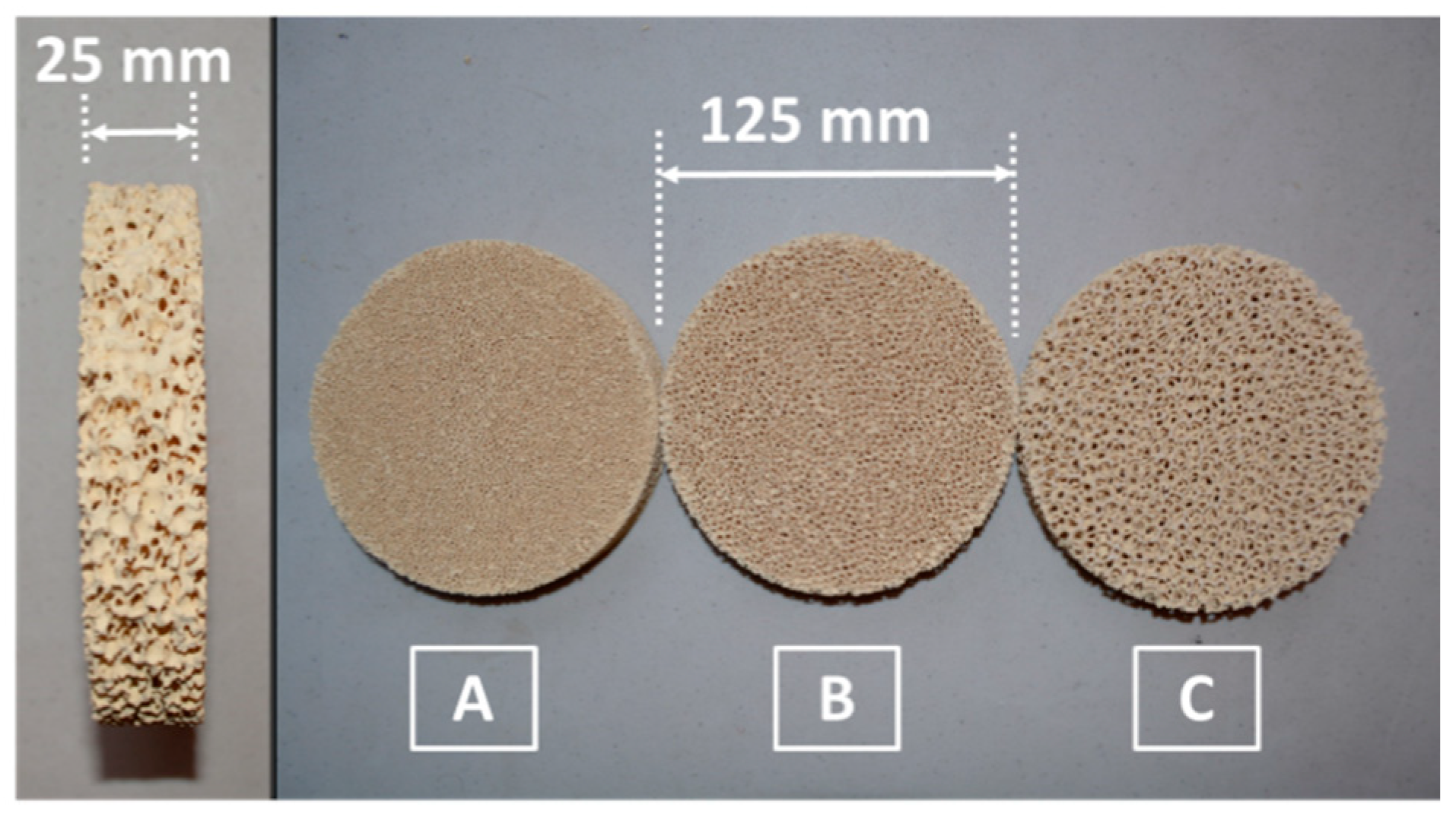
Figure 1. Volumetric absorbers used in experimental tests. partially stabilized zirconia (PSZ) foam filters with pore density: (A) 30 PPI (pores per inch), (B) 20 PPI, and (C) 10 PPI.
Energies 14 02506 g001
Figure 2. Reactor Cross-section. (1) Gas inlet manifold, (2) Reactor body, (3) Flat Glass Window, (4) Alumina thermal insulator, (5) Volumetric absorber, (6) Pyrometers, (7) Water-cooled aperture stop, (8) Window cooling nozzles.
Energies 14 02506 g002
Figure 3. Distribution of thermocouple probes in the porous absorber (1): front face (yellow), rear face (red), absorber edge (blue), and insulation interface (green) (2). The red line indicates the direction of pyrometer readings (3).
Energies 14 02506 g003
Figure 4. (a) Solar reactor operation diagram showing the temperature (T) and pressure (P) sensors, the mass flow controllers (MF), and the gas inlet/outlet, also is illustrated the incoming radiation flux (1), the water reservoir (2), the compressed air tank (3), and the air extractor (4). (b) The solar reactor installed in the high radiative flux solar furnace (HoSIER), the reactor (1), solar concentrator panel (2), and front pyrometer (3).
Energies 14 02506 g004
Figure 5. Temperature data for 10 PPI absorber obtained throughout the test. Values were averaged over the sensors located in the absorber body.
Energies 14 02506 g005
Figure 6. Front, back, and side face temperature data obtained during steady-state operation under different flow rates. Values were averaged over the sensors located in the absorber body.
Energies 14 02506 g006
Figure 7. Air inlet and outlet temperatures data obtained during steady-state operation under different flowrates. Values were averaged over the sensors located in the absorber body.
Energies 14 02506 g007
Figure 8. Isothermal surfaces corresponding to the 20 PPI absorber obtained from numerical simulations.
Energies 14 02506 g008
Figure 9. Isothermal surfaces on the z-y plane (perpendicular to thickness) of the absorber material. (a) 10 PPI, (b) 20 PPI, and (c) 30 PPI.
Energies 14 02506 g009
Figure 10. Temperature of the solid and the gas as a function of depth, from the analytical model, for the 20 PPI absorber with different air flowrate. (a) 30 L/min−1 and (b) 10 L/min−1.
Energies 14 02506 g010
Figure 11. Total conductivity (kt) obtained from the simulations for different linear pore densities (red squares) and a trendline for these values (red dotted line). The effective conductivity (ke) [43] for the 20 PPI absorber (black circles) with the expected scaling for this quantity (black dotted line) based on the assumption of radiation heat transfer dominance [57].
Energies 14 02506 g011
Table 1. Experimental (Exp) temperature data in the porous medium and simulations (Sim) predictions for the 10, 20, and 30 PPI absorbers, with 30 L/min−1 in air flowrate. RMS refers to root-mean-square deviations.
Location10 PPI20 PPI30 PPI
x (mm)y (mm)z (mm)Exp (K)Sim (K)Exp (K)Sim (K)Exp (K)Sim (K)
27027117211961203120412031108
272327786795685681685603
−30027110812101103120111031102
−302327795804642688642609
−300−3011071056108610771086994
−3023−30820727645630645560
270−30110111011063111210631024
2723−30735745574644574572
RMS5%6%7%
Publisher’s Note: MDPI stays neutral with regard to jurisdictional claims in published maps and institutional affiliations.