Article

Dynamic Probabilistic Risk Assessment Based Response Surface Approach for FLEX and Accident Tolerant Fuels for Medium Break LOCA Spectrum

1
Rensselaer Polytechnic Institute, 110 8th Street, Troy, NY 12180, USA
2
Idaho National Laboratory, Idaho Falls, ID 83415, USA
3
Korea Atomic Energy Research Institute, Daedeok-daero 989 Beon-gil, Yuseong-gu, Daejoen 34057, Korea
*
Author to whom correspondence should be addressed.
Energies 2021, 14(9), 2490; https://doi.org/10.3390/en14092490
Submission received: 5 April 2021 / Revised: 23 April 2021 / Accepted: 23 April 2021 / Published: 27 April 2021

Abstract

:
After the Fukushima Daiichi Accident, the safety features such as accident tolerant fuel (ATF) and diverse and flexible coping strategies (FLEX) for existing nuclear fleets are being investigated by the US Department of Energy under the Light Water Reactor Sustainability Program. This research is being conducted to quantify the risk-benefit of these safety features. Dynamic probabilistic risk assessment (DPRA)-based response-surface approach has been presented to quantify the FLEX and ATF benefits by estimating the risk associated with each option. ATFs with multilayered silicon carbide (SiC), iron-chromium-aluminum, and chromium-coated zirconium cladding were considered in this study. While these ATF candidates perform better than the current zirconium cladding (Zr), they may introduce additional failure modes in some operating conditions. The fuel failure analysis modules (FAMs) were developed to investigate ATF performance. The dynamic risk assessments were performed using RAVEN, a DPRA tool, coupled with RELAP5 and FAMs. A cumulative distribution function-based index provided a mean of comparing the benefits of safety enhancements. For medium break loss of coolant accidents, FLEX operational timing window for each fuel type was estimated. Among these ATF candidates, SiC-type ATF was the most beneficial candidate for an increased safety margin than Zr-based fuel and was found to complement FLEX strategies in terms of risk and coping time.

Graphical Abstract

1. Introduction

The safe and economic operation of nuclear power plants (NPPs) is always the nation’s top priority. After the Fukushima Dai-ichi NPP accident, more efforts have been placed to augment the safety by introducing new safety features that may provide an additional barrier to prevent radioactivity releases to the environment. As a result, the accident tolerant fuel (ATF) development program was initiated by the Department of Energy (DOE) Office of Nuclear Energy within the Fuel Cycle Research and Development (FCRD) Advanced Fuels Campaign (AFC) with a goal to provide alternative fuel system technologies that may enhance the safety and endurance of the fuel against such accidents [1]. Since the Fukushima accident evolved as a result of the loss of the ultimate heat sink due to the extended loss of AC power (ELAP), the Nuclear Energy Institute (NEI) recommended implementing the diverse and flexible coping strategies (FLEX) [2] that can provide an additional barrier to such accident up to 72 h of the accident initiation.
The application of ATF to the existing NPP fleet is expected to provide benefits [3] as it reduces the burden on the emergency core cooling system (ECCS) during a severe accident by decreasing the total amount of heat generated from the cladding oxidation in a high-temperature steam environment. In conventional zircaloy (Zr), the significant heat generation due to oxidation starts at 1000 °C. Still, the reaction and heat generation are considered controllable by ECCS cooling capabilities until the failure limits of peak cladding temperature (PCT) of 1204 °C [4]. Contrary to Zr cladding-based fuel, ATFs provide a significant safety margin in these PCT limits with reduced oxidation and hydrogen generation rate [3]. These additional PCT limits also provide additional risk margin in design base accidents (DBA). As discussed earlier, ATF technology provides more resistance and additional margins to thermal failures. However, it may have other failure modes that need to be addressed. For example, Multilayered silicon carbide has a high melting point of 2700 °C but can fail from brittle fractures due to the differential pressure loadings and thermal stress [5]. These days, the ATF candidates that are being explored include silicon carbide (SiC) clads [5,6], chromium-coated zircaloy (Cr-coated Zr) [7,8], iron-clad (FeCrAl) [9,10], metallic fuel and uranium silicide (U3Si2) [11]. In this paper, we investigated the three types of near-term ATF options within the DOE advanced fuels campaigns (AFC) directive for each class of silica, alumina, and chromium; multilayered SiC, iron-clad (FeCrAl), and Cr-coated Zr.
Another safety feature other than ATF is FLEX. The Fukushima Dai-ichi accident resulted from an external event that led to an extended loss of AC power (ELAP) event, leading to the loss of the ultimate heat sink and ultimately to the core damage to three of the reactors at the site. To reduce the risk of losing safety functions such as core heat removal, NEI has developed a guideline [2] of the FLEX. Kevin et al. [12] demonstrated the applicability of the FLEX strategy to low-pressure accidents with a case study of a large break loss of coolant accident (LBLOCA), where the loss of cooling occurs due to the recirculation failure either because of common cause failure of the isolation valves or the blockage of the pumps suction due to debris generated inside the containment. In the cases in which the safety injection system fails before the recirculation phase, the time to utilize FLEX was not enough to prevent the core degradation. Similarly, if the break size is too small (~2 inches), even with the operation of both pressurizer relief valves, there will be a significant inventory loss, and core uncovering will occur before the system pressure can be reduced to the FLEX injection pressure [13]. A few studies [14,15,16] have also been conducted to demonstrate the applicability of the FLEX strategies in high-pressure accidents such as the station blackout (SBO) accident scenario, in which FLEX pumps can be deployed to inject the coolant directly into the steam generator to remove the decay heat of the core.
The introduction of the ATFs into the LWR fleet is planned by the U.S. Research and Development program in the latter half of the 2020 decade. To date, there has not been extensive research addressing the effect of FLEX implementation with ATF in various NPP accident conditions. Since NPP is a complex system in which the system response varies with uncertainty propagation due to system components and their interactions, the dynamic risk assessment framework presented in the author’s previous study [17] has been extended to study the combined risk effect of ATF candidates and FLEX. To estimate the plant response over a wide range of accident scenarios with varying uncertainties associated with the plant components and operations, we employed a response surface approach in this research. This response surface approach is imperative in evaluating the effect of uncertainties associated with the recovery of the safety systems or the risk effect of new safety feature(s).
To evaluate the effect of ATF and FLEX, we divided the accidents into two sub-categories with respect to the FLEX deployment approach, the high-pressure accident scenarios (for example, SBO) in which the proper FLEX strategy is to inject the coolant into the secondary side, and low-pressure accident scenarios (For example LOCA) in which the FLEX strategy is to inject into the primary or safety injection system piping by the onsite emergency response team. In this paper, the low-pressure accident scenario medium break loss of coolant accident (MBLOCA) is presented. The complete break spectrum of MBLOCA ranging from 2 inches to 6 inches break diameter is selected for this study. This range is imperative with respect to the deployment timings of the FLEX strategy. As discussed earlier, if the safety injection system fails at the early stage of transient occurrence, there is a limited time to make the coolant injection available using FLEX depending on the established FLEX strategies [18]. If the break size is small, the rate of depressurization is too low such that even with the operation of pressurizer relief valves, the core uncovers before the accumulator starts injection. For break sizes greater than 6 inches, the depressurization is too fast that core damage occurs before the FLEX is initiated. The core damage timings for SiC for large break LOCA is reported to be less than 450 s in the author’s previous study [17].
One of the objectives of this study is to evaluate the benefit of different ATF candidates in terms of the additional coping time (CT) margin compared to Zr. Gurgen and Shirvan [19] defined CT as “the initiation time that assumed mitigation actions keep the clad temperature below its melting point.” In this research, the fuel may fail due to other failure mechanisms (e.g., fracture due to thermos-mechanical stresses), we define the coping time as the available time for mitigation actions to prevent the core damage. As the additional time gain from ATF can provide the margin for the recovery of safety systems and mitigation actions. FLEX is one of the mitigation strategies that can be implemented to recover the lost safety functions. So, the second main objective of this study was to evaluate the FLEX’s benefit and estimate its operation time window with each fuel candidate. A cumulative distribution function (CDF) based sensitivity indicator [20] was leveraged to quantify the benefit of new safety feature(s) over the accident trajectory. This metric is used to compare the benefits gained from each ATF candidate and FLEX and the combination of these options.
This paper is organized as follows; Section 2 presents the systematic way of establishing the failure criteria for each ATF fuel candidate. Section 3 provides an overview of the dynamic-risk-assessment-based response surface methodology and the description of interconnecting module’s functionality. Section 4 provides the application of the methodology to a medium break loss of coolant (MBLOCA) case study with results and discussion, and Section 5 gives the conclusion of the study.

2. ATF Failure Modes

As discussed earlier, the ATF cladding provides an alternative to reduce the amount of heat generated by zircaloy-based cladding oxidation and, consequently, reduces the ECCS burden. In this manner, ATF minimizes the temperature rise gradient and ultimately delays the core degradation process. This delay provides additional CT and reduces the threshold on the cooling required to mitigate the accident progression [3]. Although the new fuel has the advantage of reducing the heat generation due to oxidation, it may have different failure mechanism forms that have not surfaced in Zircaloy-based claddings. Table 1. summarizes the failure criteria selected and implemented for various ATF candidates for the present study. The material properties and behavior models are discussed in the following sections for each ATF type. For the simplicity of our research, we assume ATF claddings with standard UO2 pellet design with gap and cladding thickness of conventional fuel.

2.1. SiC Cladding

The SiC model used in this paper was utilized from one of the authors’ previous work [6,17]. The ATF model used is a triple-layer SiC [21] as it provides more endurance compared to the double-layer SiC, this has also been concluded in the author’s previous work [6]. Figure 1. shows the triplex layer structure, the inner layer (R1-R2) and the outer layer (R3-R4) are chemical vapor deposition layers, while the middle layer (R2-R3) is a chemical vapor infiltration SiC layer made up of SiC fibers bonded with SiC matrix. SiC has the advantage of reduced oxidation rate and higher melting temperature over conventional zircaloy cladding. However, it is prone to mechanical failure due to thermal shocks. In an accident such as a loss of coolant accident, the core may be damaged either due to the excessive loss of coolant inventory or core quenching due to the introduction of cold water to hot uncovered fuel assemblies. These thermal shocks occur because of thermal expansion caused by the pressure differential between the fuel rods and the coolant resulted in thermomechanical stresses that propagate in the radial, hoop, and axial directions. The tensile fracture occurs when these thermomechanical stresses concentrate around random preexisting flaws. Equation (1) provides the probability that a SiC cladding specimen does not undergo a tensile fracture.
P s V = exp 1 V 0 V σ r r σ 0 m + σ θ r σ 0 m + σ z r σ 0 m d V
where, σ is the mechanical stress, θ is the hoop stress, z is the stress in axial directions, σ0 = Weibull characteristic strength, and m is the Weibull modulus [23].
Stochastic failure mode does not guarantee core safety even when the ECCS successfully performs its functions. The decreasing cooling capability of the ECCS below its design criteria increases the cladding failure probability. At an absolute minimum ECCS performance threshold, the cladding temperature may reach the SiC decomposition temperature of 2730 °C, and it fails deterministically.

2.2. FeCrAl Cladding

FeCrAl-alloy is also considered a strong ATF candidate because of its higher resistance to oxidation than the zircaloy-based fuel. The oxidation rate for FeCrAl is 1000 times lower than Zr [24]. However, the thermal neutron cross-section of FeCrAl is 10 times that of Zr, which results in thinner cladding and larger fuel pellet size with more enrichment to compensate for the higher neutron absorption. This neutron absorption leads to the higher fuel cost in the case of FeCrAl. The oxidation rates of FeCrAl are low enough that a reasonable assumption is that FeCrAl cladding will not oxidize at all [24]. Thus, the design of the uranium dioxide (UO2) pellets much also be changed to introduce the FeCrAl cladding. For our study, we considered standard UO2 pellet design for simplicity.
As shown in Table 1, the FeCrAl clad can fail at a melting temperature of 1500 °C or fracture due to the overstress when the hoop stress exceeds the ultimate tensile strength (UTS). The UTS is calculated as a function of temperature, as given in Table 2 [22].
Various FeCrAl-alloys containing different weight percentages of chromium and aluminum, including APMT, C06M, C35M, and C36M, which are considered the potential candidate for iron clad. It was concluded in the Yamamoto et al. [25] that C35 MN processed at 800 °C exhibits an excellent sub-grain structure and exhibited 25% better strength over other FeCrAl alloys. So, the thermal and mechanical properties of C35 MN FeCrAl alloy were selected to evaluate failure criteria for the accident scenarios.

2.3. Chromium-Coated Zircaloy

Another most straightforward and immediate approach to reduce the heat generated from the clad oxidation is to apply a protective coating on the surface of zirconium-based alloys [26]. There is a very minimal effect on thermomechanical properties of Zr cladding if the thickness of the coating is minimal (<20 μm) [8]. This layer protects Zr’s underlying layer from high-temperature steam conditions and lowers clad ballooning rate [3].
When zircaloy is coated with chromium, an interfacial solid-state reaction occurs between the metal and the coating material to form an intermetallic layer of ZrCr2 between the zircaloy and chromium that result in the eutectic isotherm on each side of the layer. The higher eutectic temperature occurs at 1592 °C and lower at 1332 °C [7,26]. Therefore, we set 1332 °C as the thermal failure limit for Cr-coated Zr.
Several studies [8,11,16,26] on the different chromium coatings ranges vary from 20 μm to 50 μm. In this paper, we selected 20 μm as the small coating thickness. It was observed that increasing the thickness might cause additional resistance to the heat transfer to the coolant, resulting in a higher fuel centerline temperature. The thermal conductivity and specific heat capacity for pure chromium metal were selected for the additional chromium layer at Zr fuel’s surface.

3. Dynamic Probabilistic Risk Assessment Methodology

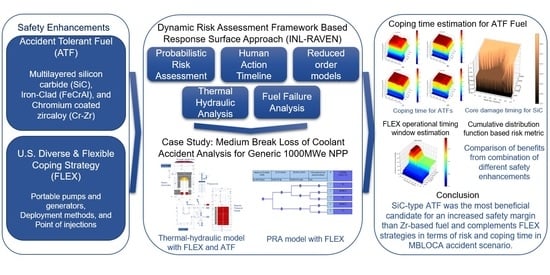
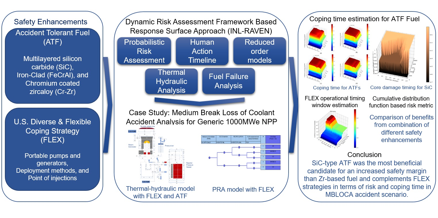
Although the research has shown that the ATF is more oxidation-resistant as compare to the conventional zircaloy-based fuel, one needs to model the behavior of the ATF properly, integrate this model into the nuclear power plant model and capture the effect of uncertainties to analyze the benefit of the ATF in the different accident scenarios. On the other side, FLEX strategies were developed to provide additional coping capabilities to prevent the core damage in extreme accident conditions. Since these two features are going to be implemented in the near future, the presented methodology was developed with an aim:
  • To quantify the benefit of ATF in various accident scenarios,
  • To quantify the benefit of FLEX in various accident scenarios,
  • To analyze the combined benefit from the ATF and FLEX,
  • To study the effect of uncertainties associated with the FLEX deployment,
  • To study the effect of uncertainties associated with other variables (for example ECCS injection timings)
  • To estimate the FLEX operational timing window in various accident scenarios.
Since the accident evolves on the system response to the initial perturbation and their interaction with the system in a dynamic manner, the framework introduced in previous work [
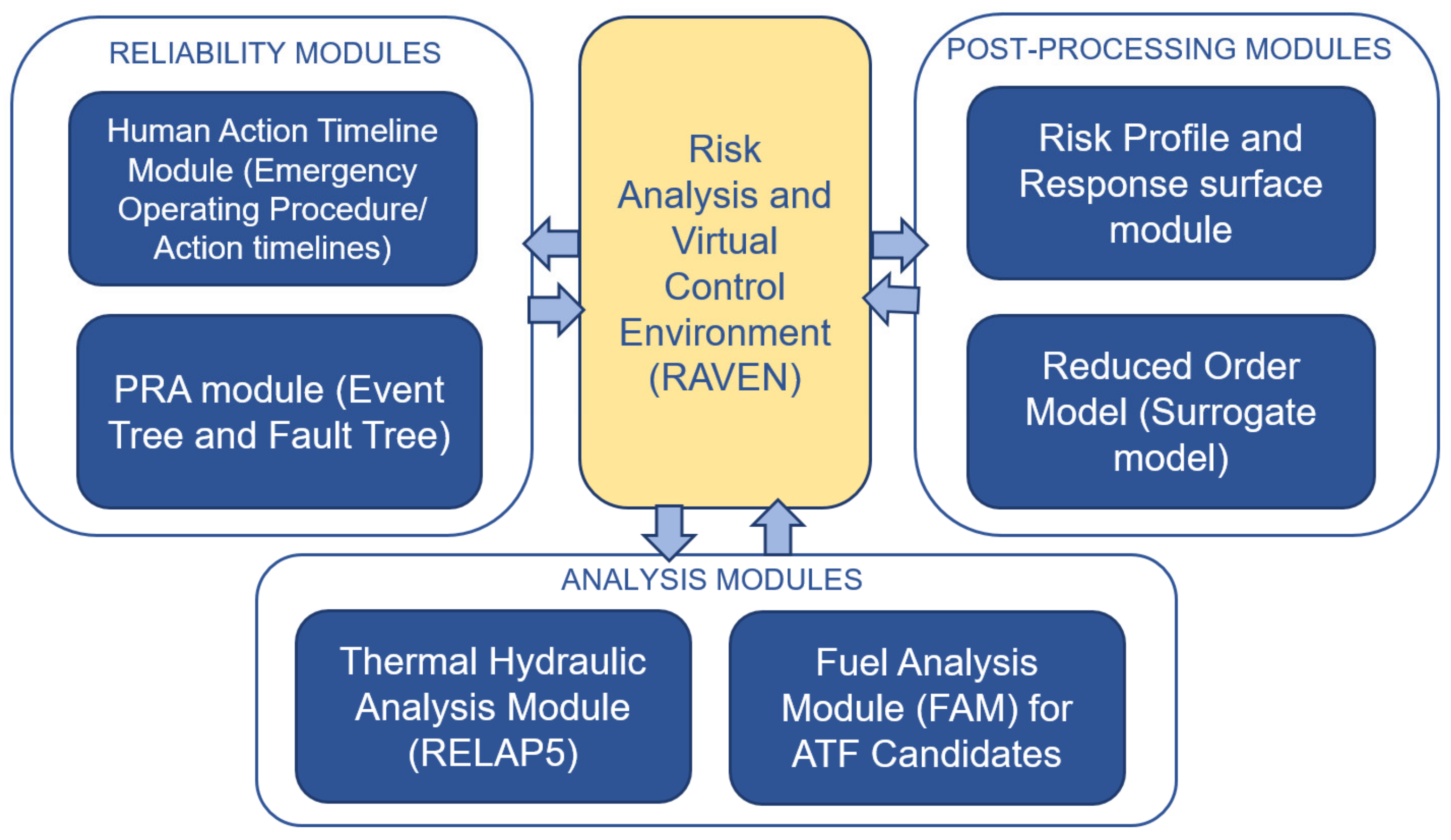
17] is extended to study the effects of additional ATF candidates and FLEX. Additional ATF fuel failure analysis modules (FAMs) and risk profile and response surface modules were integrated to systematically perform a dynamic risk assessment, as shown in Figure 2. The failure data of the portable equipment and human reliability calculations for the FLEX strategy were implemented in the reliability module. At the same time, the thermal-hydraulic model of FLEX was added to the thermal-hydraulic analysis module. A provision was made to quantify the CDF-based importance measure of each new safety feature to evaluate their benefit over the accident trajectory. There are three main parts of this framework; reliability modules, analysis modules, and post-processing modules. These modules are connected to a control module that is based on the Risk Analysis and Virtual Control Environment (RAVEN), which was developed at the Idaho National Laboratory (INL) [27,28]. The functions of each module are described in the following sections.

3.1. Reliability Modules

As shown in Figure 2, there are two modules inside the reliability module block. The first module is the human action timeline module; this module provides the timeline distributions of the operator’s actions to the RAVEN control block. The human action timeline module block’s primary function is to provide the operator’s timeline information data obtained under simulated emergencies. This module contains the operator performance and reliability analysis (OPERA) database [
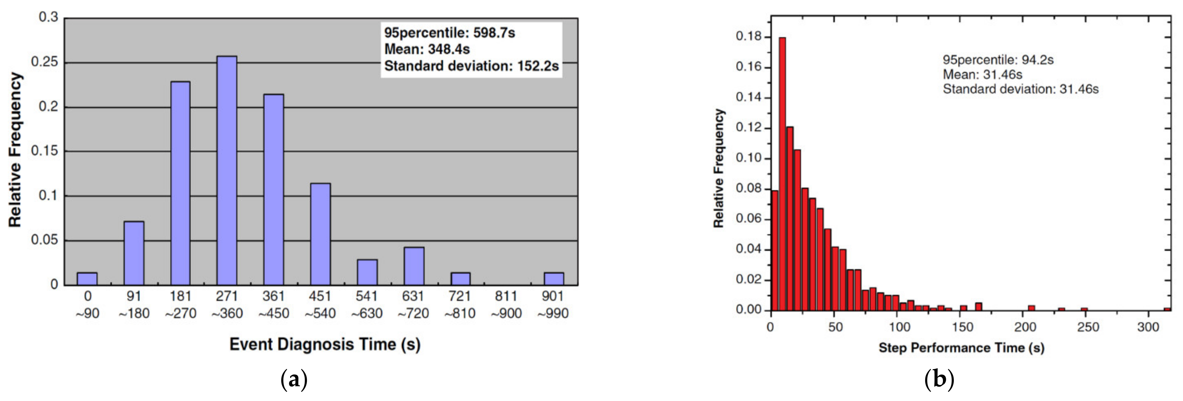
29] and the information from EOPs. One of the most critical tasks during an accident scenario is the diagnosis of which event has occurred. The OPERA database established the timeline information (i.e., the total time for standard post-trip actions and the diagnosis time) from the reactor trip to completing the diagnosis procedure.
Moreover, OPERA also contains the step performance time data within the tasks. Figure 3a,b depicts the timings distribution of the event diagnosis procedure and step performance time for different accident scenarios, respectively. Normal distribution and exponential distribution were fitted to the event diagnosis time and step performance time to calculate the most probable timings, respectively. The mean and standard deviation of the distribution were reported in the OPERA database. These distributions were utilized with the assumption that the number of steps is independent of each other. In that case, each task can be combined to give a gamma distribution [30].
This block also contains the human reliability data for the FLEX deployment collected from previous research [13,14,15,18]. Detailed modeling of FLEX portable equipment is discussed in Section 3.2. The human action timeline module provides the operator action timeline to recover the failed safety system such as the ECCS and auxiliary feedwater recovery if automatic actuation signal fails to generate and deploy and operate the FLEX portable equipment. Since the FLEX strategies are relatively new, there has not been extensive research supported by the infield experiments. Previous studies [18] suggested three deployment methods for the FLEX portable equipment. First includes only the pre-staging of the portable equipment that requires the directions to the responsible personnel to move to the area and initiate the FLEX portable equipment. The equipment was already deployed to the site location. The second includes the deployment by the initial emergency response team in addition to the first strategy, so it takes more time for FLEX initiation. Third, the FLEX equipment deployment by the offsite emergency response team requires additional time to send a notification to the offsite emergency response team with appropriate directions. This option may require more time than the first two deployment methods. The minimum time delay of 2 h was estimated for the SBO, including the time for DC load shedding in the reference study [18]. In another study [13], the total loss of feedwater accident scenario was analyzed with the FLEX strategy by considering the minimum time delay of 45 min. Since the MBLOCA is a fast propagating scenario, we select the delay of 45 min in the case of LOCA accidents with a log-normal distribution.
The second module in this block is the probabilistic risk assessment (PRA) module. It contains the complete PRA model for a generic 1000 MWe pressurized water reactor (PWR)-based NPP. One of this module’s primary functions is to provide the sequence of the event in combination with the human action timeline module block as it also contains the timeline information of the operating procedure during an emergency. The sequence information is provided from the accident event trees (ET), and the component reliability information is provided from the fault tree (FT) models that correspond to the headers in the ET. This module’s two primary inputs to the RAVEN control block are the accident sequence information and the component failure data. This failure data may include the components that fail to start/operate either due to the failure of automatic actuation signal generation or the mechanical failure and their running failures over the accident trajectory.
The FT model for FLEX was also developed and incorporated into the PRA model for generic 1000 NPP (PRA module). Since the purpose of the PRA module is to provide the failure distributions to the RAVEN control module, only the failure distributions of the equipment will be relevant, and details for the FT development are not included in this study.

3.2. Analysis Modules

This block consists of two modules. One is the thermal-hydraulic analysis module, and the other is the fuel failure analysis module (FAM). The FAM’s purpose is to model the ATF mechanical failures that cannot be implemented in thermal-hydraulic code such as RELAP5 [31]. The Thermal hydraulic module contains the two-loop RELAP5 thermal-hydraulic model for generic 1000 MWe NPP adapted from previous research [32,33]. Since this study aims to analyze the benefit of FLEX with different ATF fuel types, provisions of these features were made in the input model. As discussed in Section 2, thermal properties were specified in the input model according to the type of ATF analyzed. 
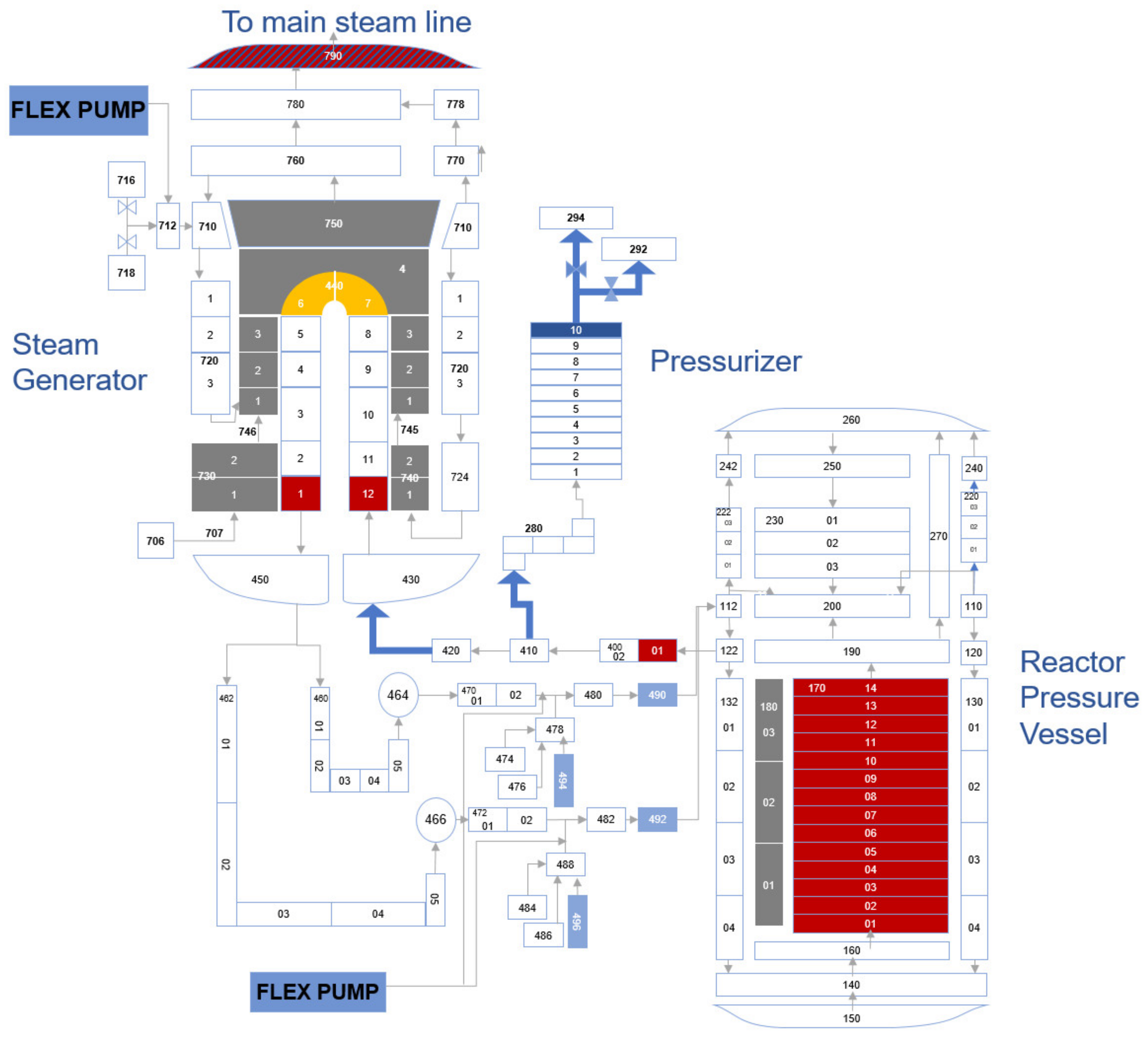
Figure 4. shows only one loop with a pressurizer for the two-loop generic 1000 MWe PWR-based NPP. The target model is a two-loop NPP with two cold-legs with reactor coolant pumps, one hot-leg, and a steam generator at each loop. There is only one pressurizer at the hot-leg as shown in Figure 4. Since the second loop was identical, we show FLEX injection points in only one loop of the RELAP5 input model. Two FLEX pumps, BA150H and HH125 [13] were modeled with their performance curves obtained from the manufacturer manuals. These provisions were made in the input so that these pumps can inject coolant directly into the primary side via the safety injection piping and into the secondary side via the auxiliary feedwater injection piping. Since the depressurization is self-sufficient in most of the cases of MBLOCA, we will focus on the FLEX strategy with direct injection into the primary side by the local emergency response team using the pre-deployment method as discussed in Section 3.1. However, the depressurization via pressurizer relief valve was considered for the cases with smaller break sizes (<3.5 inches).
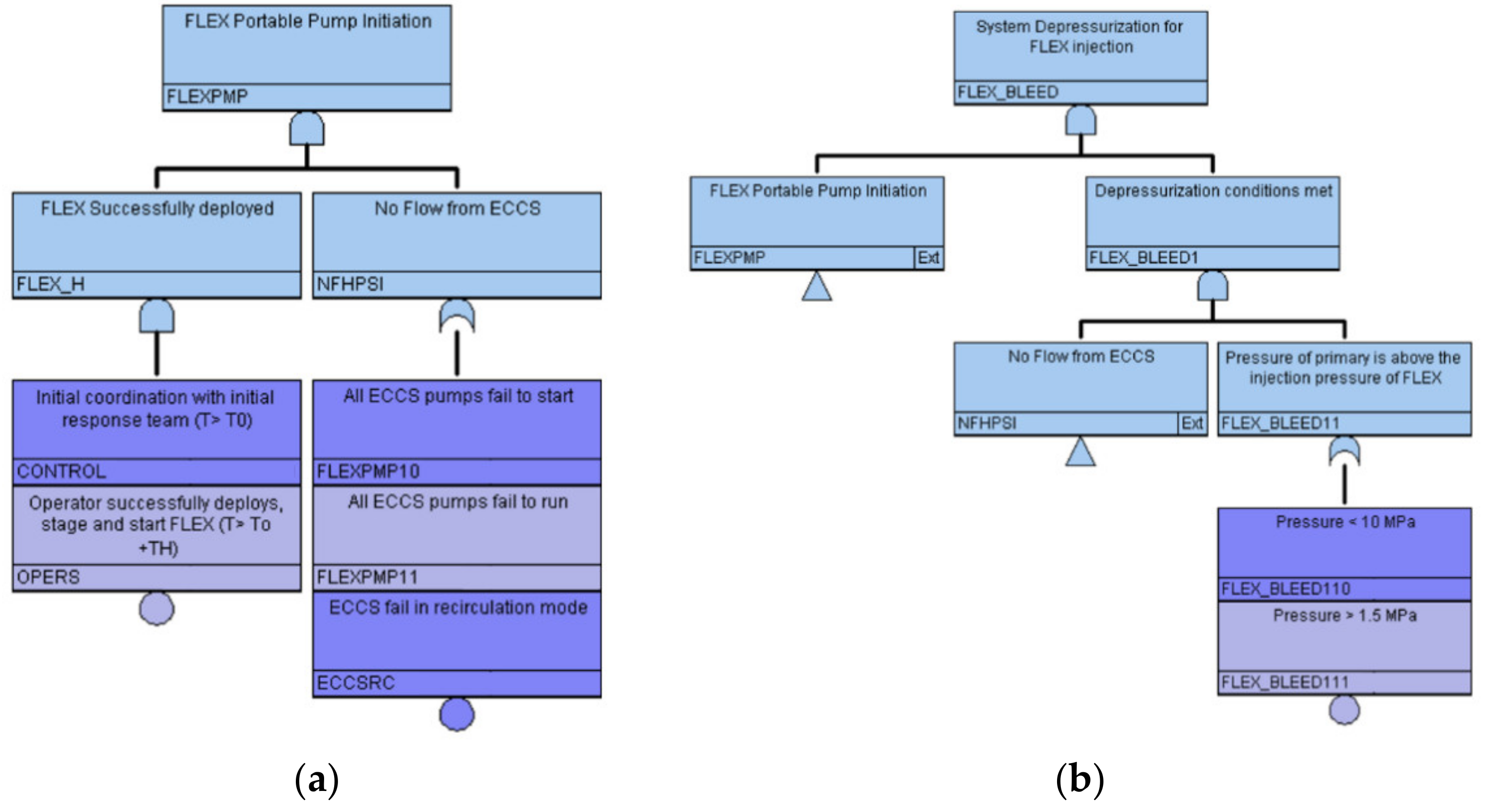
Since there has not been sufficient research that can provide the logic for performing the depressurization to inject FLEX, the actuation logic for FLEX was modeled for low-pressure accidents. Figure 5a shows the trip logic for the FLEX deployment to the primary side in the RELAP5 input model. The FLEX pump injection was considered successful if it meets the minimum time of initial coordination with the onsite deployment team and the operator’s success of starting and staging the portable generator and pumps. However, the timings of operation may lead to the success and failure of the FLEX functions. This will be discussed in detail in Section 4.4 and Section 4.5. Figure 5b shows the logic for the primary depressurization for FLEX injection. The operator will start depressurization once he/she identifies that FLEX equipment has been deployed and ECCS fails to inject the coolant into the primary loop after the generation of the ECCS actuation signal or the conditions such as low pressurizer pressure.
Since RELAP5 is a thermal-hydraulic code, it has a limitation to model the stochastic and mechanical failures such as failures due to overstress. Therefore, separate modules were developed to model the mechanical failure of ATF candidates. The modeling details are provided in Section 2. Therefore, once the thermal-hydraulic simulations are completed for each fuel type, results are then transferred to the RAVEN control block. RAVEN executes the FAM simulation on each output to analyze the mechanical failure in each ATF fuel type. Two FAMs were developed to model the mechanical failure for SiC and FeCrAl. Due to the very fine layer for chromium-coated zircaloy, the failure criteria were modeled in the thermal-hydraulic input. RAVEN executes the FAM on each thermal-hydraulic scenario’s output, compiles the results, and sends it to the post-processing module block.

3.3. RAVEN Control Module

RAVEN is a tool developed at the INL acting as a control logic driver for the interacting modules, that is, reliability, analysis, and post-processing modules. The RAVEN can systematically interact with these modules with an input defined in XML [
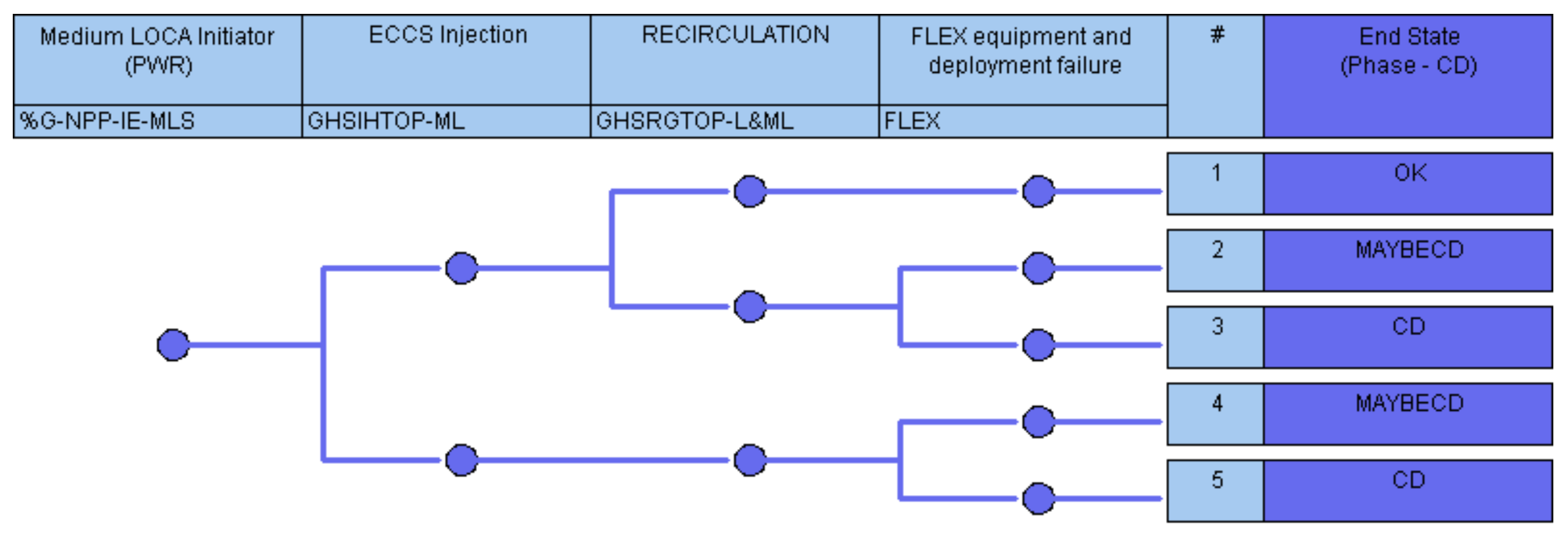
34] format. Sub-input text files for the thermal-hydraulic module and FAM need to be defined within the XML input. To determine the RAVEN XML input, information from the reliability module is fetched first to generate the accident sequence based on the event tree’s headers and the human action timeline from the emergency operating procedures. The headers in the ET correspond to the FT that defines the branching conditions for the accident scenarios. For this paper, we focus our study on MBLOCA accident scenarios so that these conditions may include the following:
  • Pump fails to start (for example, ECCS pumps)
  • Pump fails to run (running failures over the accident simulation time)
  • Automatic actuation signal fails to generate (for example, ECCS auto actuation)
  • Recovery of the failed system by the operator using human action timeline information.
  • Human action timeline distribution for the actions such as secondary cooldown and primary depressurization.
  • Human action timeline distribution for the FLEX deployment and actuation
  • Other failures (such as recirculation failure due to failure of sump isolation valves).
The uncertainty distribution of the variables corresponding to the systems’ failures and the component, including the human action timeline distribution, were then extracted from the reliability module and provided to the RAVEN control block. It is imperative to make the provision of these variables in the RELAP5 thermal-hydraulic input before execution. It is to be noted that more than one variable from the reliability module can correspond to a single variable in the input of RELAP5. Many sampling techniques are available in the RAVEN platform, including the Monte-Carlo, Grid, Latin-hypercube, dynamic event tree, and hybrid [28]. Since the focus of this study is to obtain a risk profile response surface that covers the complete spectrum in a three-dimensional space, we selected grid sampling so that the grid size may vary with respect to the sensitivity of the study (e.g., ECCS recovery timing in a LOCA accident is essential in the early stage of transient initiation, so the grid size at the beginning of the transient is narrow and become sparser and sparser at the later stage). The RAVEN generates accident scenarios with the combination of all the variables defined in the grid. The grid size should be selected very carefully as the number of generated accident scenarios depends on the grid’s size and the number of variables with uncertainties. If the grid size resolution is too high, the number of the generated accident scenarios will be too large to handle and lead to data handling and out-of-memory size issues. Therefore, to limit the number of accident scenarios, we selected each variable’s grid size based on the expert opinion (for example, the grid size for ECCS and FLEX injection is narrow at the beginning of the transient and becomes wider as it reaches the end of the simulation). Moreover, the accident scenarios are generated by dividing the event tree sequence into the required number of sub-trees to remove the illogical branches. For example, if the ECCS pumps automatically start successfully and operate without failure, there is no need to recover the ECCS through manual actuation.
This RAVEN module is also linked with an external post-processing module that contains multiple python scripts, and a MATLAB-based reduced-order model (ROM) developed specifically for the dynamic risk assessment framework [17].

3.4. Post-Processing Modules

As shown in Figure 2, the post-processing module block contains two sub-modules: risk profile and response surface module and reduced ordered model (ROM). The post-processing module is an external python module to RAVEN that fetches the generated accident scenarios from the RAVEN block, processes them, and generates output to give the risk profile or a response surface. As mentioned earlier, grid sampling was utilized to create the accident scenarios’ branches. In the grid sampling, each branch has its associated probability weight w n [35] where n = 1 N w n = 1 and n is the simulation index (n = 1, 2, 3, …., N) and N is the total number of generated accident scenarios. If there are X variables with uncertainties and each variable has a grid size of Mx, then N can be calculated as N = x = 1 X M x . RAVEN calculates the probability weights of variables with uncertainties by calculating the probability (pvx) from the given distribution of variables for the given grid size and then normalized it. For example, if a variable x is normally distributed and is divided into M grids, then pvx is calculated by calculating the CDF value at the specified grids (v = 1, 2, 3, …M), the variable probability weights (ωvx) are then calculated by dividing these probabilities by v = 1 M p v . Similarly, probability weights for X number of variables with uncertainties (ωv1, ωv2, ωv3, …, ωvX) are calculated. The associated branch probability weight w n is calculated by taking the product of all the probability weights (ωvx) of the variables with uncertainties corresponding to the nth branch w n = x = 1 X ω v x . These branch probability weights are used to calculate the conditional core damage probability (CCDP) given time t of N number of accident scenarios as provided by Equation (2) [17].
P f | t = n = 1 N P f n | t . w n
where
f = core damage state for N scenarios,
w n = probability weight for nth scenario,
f n = core damage state for nth accident scenario,
t = time of accident progression in seconds.
To calculate the CCDP with respect to any given conditions (e.g., the failure probability given the ECCS fails to actuate), this block selects the number J accident scenario out of N so that j J w j 1 . Therefore, the weights are normalized using Equation (3) to give new weights w j * such that j J w j * = 1 . Equation (4) is then utilized to calculate the conditional probability with the given condition “A” that can be a single condition or multiple conditions (e.g., the failure probability given the automatic actuation ECCS fails and FLEX fails to inject).
w j * = w j / j J w j
P f | A , t = j = 1 J P f j | A , t . w j *
where,
J = the number of the scenario corresponding to condition A,
w j * = new probability weight for jth scenario,
w j = old probability weight for jth scenario,
f j = core damage state for jth scenario,
A = single or multiple conditions,
t = accident progression time in seconds.
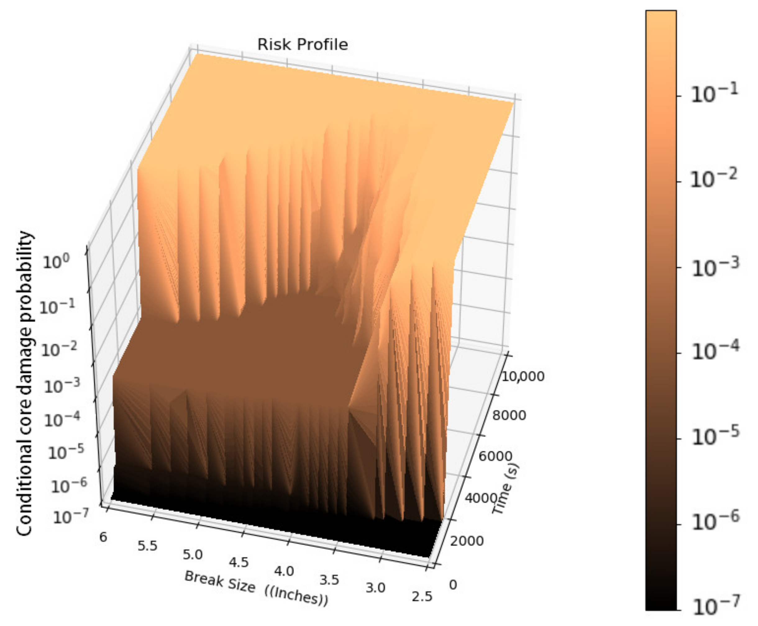
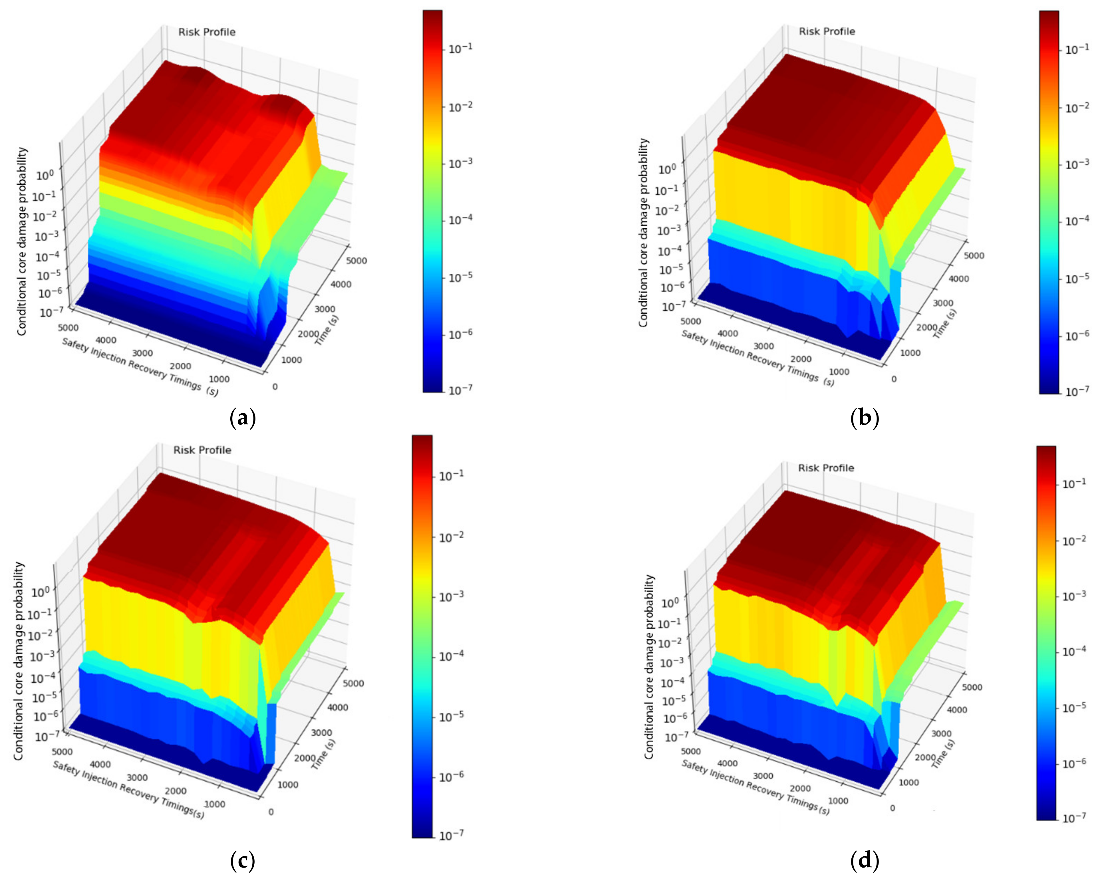
As given in Equation (4), the conditional probability is useful in getting the risk response surface in the three-dimensional space. Let us assume the variable V has been defined with a grid spacing of V1, V2, V3, V4 …. VM, to obtained a response surface for V, a matrix with width M and length t will be created using Equations (3) and (4) for the conditional probabilities P1(f1|V1, t), P2(f2|V2, t), P3(f3|V3, t), P4(f4|V4, t) … PK (fM|VM, t). Reduced-order models (ROM) from the authors’ previous work [17] and pre-established python surrogate modules take this matrix as an input and surrogates it to add enough scenarios to generate the (M + G) dimension matrix, which includes the samples (M) and generated scenarios (G). The post-processing module retrieves this matrix to convert it into a three-dimension response surface.
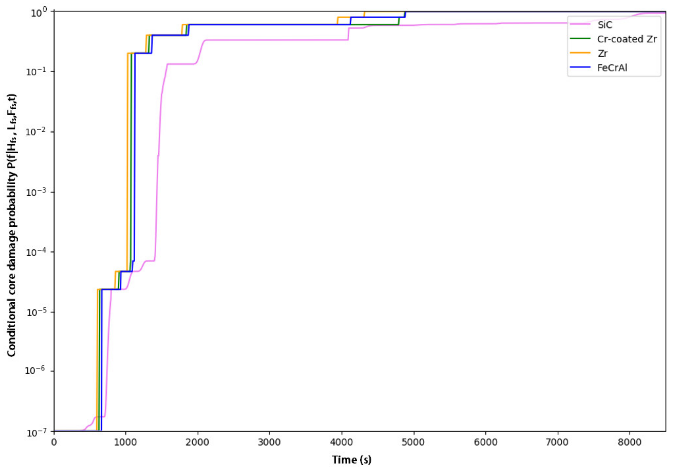
Since the purpose of this study is to evaluate the benefit of the new safety feature(s) such as ATF and FLEX over the existing capabilities, we leveraged a cumulative distribution function (CDF)-based measure to compare the benefit of each option. Liu et al. [20] introduced a new CDF importance measure SiCDF for sensitivity analysis that describes the effect of uncertainty in the model input on the variation in the output CDF. 
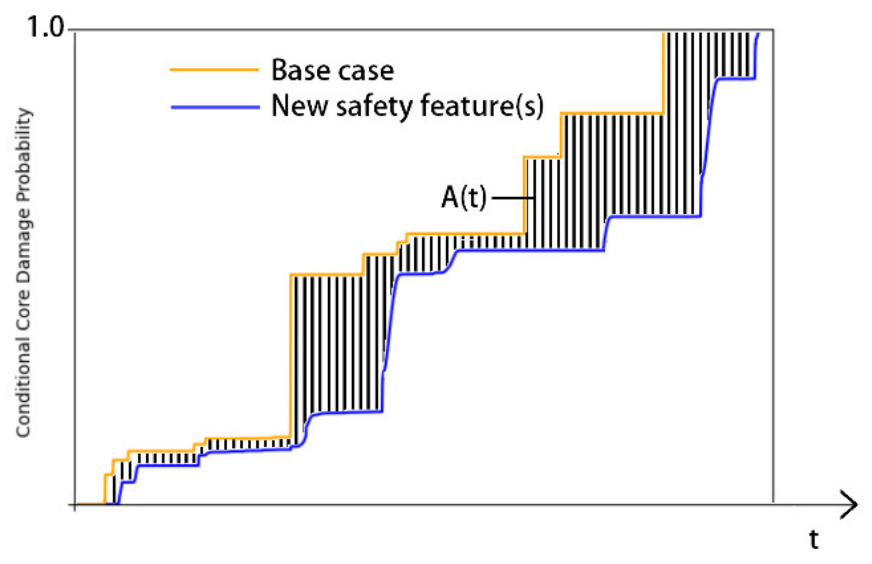
SiCDF is calculated by comparing the unconditional CDF with conditional CDFs. In our case, a similar approach was utilized, but the comparison was made between the two different CDF profiles, one that corresponds to one of the three options ATF only, FLEX only, and ATF with FLEX and the second is the conventional Zr-based fuel. The output is in the form of a cumulative CCDP profile as a function of time. The CCDP profile obtained for conventional zircaloy with the given uncertainties can be considered as a base case σb (t). A similar profile can be obtained for each of the new safety features (ATF or FLEX) or their combinations σk (t). The addition of a new feature may shift the CCDP profile, and the area enclosed by the two profiles will give the absolute deviation of the new CCDP from the base case, as shown in Figure 6. This area can be calculated either by integrating along the x-axis or y-axis as given by Equations (5) and (6), respectively. The horizontal shift of the base cumulative CCDP to the right will provide the benefit in terms of additional CT, while the reduction of CCDP value at any time t will give the risk benefits up to the time t. In other words, we can also interpret Figure 6. as the probabilistic CT of PWR-based NPP with Zr and other safety features (ATF or FLEX).
A a , t = [ σ b t σ k t ] d t
where σ b t is a CCDP risk profile with Zr (base case) and σ k t   is a CCDP risk profile with a new safety feature(s) such as ATF and FLEX.
A a , t = 0 1 [ t b α t k α ] d α
where tb(α) and ta(α) are the inverse functions of σ b t and σ k t , respectively.
E A k i , t = a f k i a . A k i , t
where f k i a is a binary distribution such that a = 1 and a = 0 correspond to the CCDP with and without adding new safety feature(s) k i and can be described as their influence on the output distribution. According to Liu et al. [20], the CDF-based sensitivity indicator will be defined as given in Equation (8).
S i C D F = E A k i , t E t
and,
E t = 0 1 t b α d α
or
E t = ( 1 σ b t ) d t
where, in our research, α is the CCDP and E t will provide the expected CT. Since the sensitivity analysis in this research aims for the benefits associated with various new safety features, we can also define the CDF-based sensitivity indicator S i C D F as “Benefit index”. It has to be noted that the time that CCDP reaches the value of 1 is indefinitely large, so we will calculate the benefit over a definite period of time t at which the base risk profile and risk profile with new safety feature(s) converge to a specific value. The enclosed area indicates the benefit of adding the new safety feature(s) k i to the existing system. This will be explained in detail for a case study of an MBLOCA in Section 4.3 and Section 4.4.

4. Medium Break Loss of Coolant Accident

4.1. Overview, Initial Conditions, and Assumptions

As discussed earlier, this study’s primary purpose was to evaluate the combined effect of ATF fuel types and FLEX coping strategies. Therefore, to evaluate the combined benefit, we selected two diverse transients, the first one leading to the high-pressure accident scenarios in which the FLEX injection is required on the secondary side, the second one leading to the low-pressure accident scenarios that require FLEX injection into the primary side. The present study focuses on the latter part only. We have selected the loss of coolant accident scenario to evaluate the benefit of each ATF fuel type and FLEX coping strategies in a systematic manner. The spectrum of the break size was selected with an aim to identify the break range that corresponds to the maximum combined benefit of the FLEX and ATF. Several pilot studies were performed to select the break spectrum for LOCA. If the break size is too large, the FLEX is only useful in events in which the ECCS injection fails in the recirculation mode. Simultaneously, if the break size is too small, even with the depressurization using two pressurizer relief valves (PORV), the core damage occurs before the primary pressure reaches the FLEX injection pressure. These conditions are also in agreement with previous studies [12,13,17].
The RAVEN-based DPRA framework allows us to generate around 40,000 samples for each fuel type, simulated using the analysis module block. The generated accident scenarios contain a combination of numerous variables so that the generated scenarios were grouped to analyze the gain in CT for each ATF candidate and then combine benefits of ATF and FLEX. Although the FLEX benefits have been evaluated previously, this study evaluates them using the integrated probabilistic and deterministic approach. Figure 7. shows the event tree for the MBLOCA analysis. According to this event tree, the first safety system to overcome MBLOCA is the ECCS injection. The headers in the event tree provide the sequence of the event in the current framework as depicted in the reliability block in Figure 2. The initial steady-state conditions for the MBLOCA accident are given in Table 3.
The break is assumed to occur on one of the four cold-legs with a size that may vary from 2 inches to 6 inches in diameter. Figure 7 shows the event tree of the MBLOCA. Once the break is initiated, it is followed by:
  • ECCS automatic actuation signal generation is successful or failed,
  • If ECCS automatic actuation is failed, whether the operator was able to recover the ECCS within the required time,
  • If the ECCS actuates successfully, whether it fails to run during the transient simulation time,
  • If ECCS is successful, whether the recirculation is successful or it may fail due to the failure of isolation valves or sump clogging due to debris in the containment.
  • If ECCS fails either at the start or during the recirculation phase, whether FLEX equipment can act as a backup to provide the required cooling in the event of the MBLOCA.
The effect of these uncertainty factors is addressed in the following sections. It should be noted that the ECCS injection system includes the active injection system using safety injection pumps and passive injection using safety injection tanks (SITs) or commonly known as accumulators. The ECCS system in the target plant consists of three high-pressure safety injection pumps (100% capacity) and two low-pressure safety injection pumps (100% capacity). Each of the first two high-pressure safety injection pumps is aligned either with Loop A or Loop B. The third pump is aligned with loop A but can be switch to Loop B if required. There are also four passive SITs designed in such a manner that an actuation of three out of four will protect the core. Each header corresponds to a fault tree, which provides the corresponding distribution for the components and systems’ failure. Table 4. shows the selected variables that are input to the RAVEN block to generate an accident scenario. As discussed earlier, the distribution for the human action timings was obtained either by combining the number of steps corresponding to the recovery action or taking the equivalent gamma distribution for the mean and standard deviation of the timing to complete a task in the OPERA database. Moreover, it is also assumed that the ECCS failure in the recirculation phase occurs at the time when the inventory in the refueling water storage tank (RWST) depletes and the ECCS suction shifts to the containment sump. This assumption was made to optimize the simulation time of the MBLOCA accident. A failure probability of 1.49 × 10⁻² was selected from the fault tree’s top event in a PRA module corresponding to the recirculation failure.
The fine grid size is required for the variables such as ECCS recovery by the operator, pump failure to run timings, break size distribution, and FLEX strategy operation to develop a smooth response surface. The finer the grid size, the larger the number of accident scenarios. A vast number of accident scenarios are generated if all the possible combinations are considered. For a number of illogical accident scenarios, for example, if ECCS automatic actuation was successful, there is no need for an operator to recover the ECCS manually were identified to save simulation time. This was done by dividing the runs into two parts; with ECCS automatic actuation success and failure. Separate RELAP5 inputs were prepared. By doing this, the total number of accident scenarios reduced to around 40,000 for each fuel type. In total, there were 160,000 accident scenarios simulated for three ATF candidates and one for conventional zircaloy. These accident simulations were performed on a high-performance PC using the analysis module as shown in Figure 2. RAVEN controls the analysis block so that FAM simulation is executed on each grid once the RELAP5 thermal-hydraulic simulation is completed.
The transient termination criteria were also established for each simulation and were incorporated in the RELAP5 thermal-hydraulic input as given below:
  • The peak cladding temperature for each ATF fuel type reaches their failure thermal limits,
  • The temperature of the hot-leg is approaching the residual heat removal system (shutdown cooling system) entry conditions (420 K and 2.7 MPa) after successful actuation of the FLEX injection system (temperature continuously decreasing or maintained at a subcooled condition).
  • The successful actuation of Low-Pressure Safety Injection System (LPSI).

4.2. Core Damage Timings for ATFs

One of the objectives of this study is to evaluate the benefits of different ATF fuel types. In order to achieve that first, the core damage timing of all the ATF fuel types was compared by calculating the conditional core damage probability given high-pressure safety injection (HPSI) pumps (Hfs), low-pressure safety injection (LPSI) pumps (Lfs), and FLEX failure to start (Ffs) at time “t” P (f |Hfs, Lfs, Ffs, t) using Equations (3) and (4). Figure 8. shows this conditional probability for ATF fuel candidates considered in this research. It was found that multilayered SiC has some advantage over the other fuel types. Cr-coated Zr and FeCrAl also have some advantages over conventional zircaloy. This figure shows the conditional probability P (f |Hfs, Lfs, Ffs, t) that corresponds to the complete range of MBLOCA (2–6 inches) and may vary significantly with the varying break size that will be discussed in the latter part of this section.
The staircase structure in the graph is due to the sparser grid size. A finer grid will make the curve smoother and more continuous. Each staircase corresponds to an initial rise in CCDP and curbing due to the failure and actuation of coolant injection either by SITs or by HPSI system for various break sizes, respectively. Even after 2000 s, the core damage was not inevitable as there may be some cases that last more than 4000 s and for the case of SiC, as long as 8000 s. The response surface with varying break sizes was developed using the DPRA framework to identify those specific cases. Figure 9a–d shows the conditional core damage probability given HPSI, LPSI, and FLEX fail to start at time t for multilayered SiC, FeCrAl, Zr, and Cr-coated Zr, respectively. All the ATF fuel types and conventional zircaloy show a similar trend with varying break sizes. There is a minimum break size (about 3.1 inches for SiC and 3.5 inches for other fuel candidates) below which the core damage is certain for all the fuel types within 2000 s, this is because the break size was not large enough to depressurize the reactor coolant system to the injection pressure of SITs. For the accidents that correspond to break size greater than 3.1 inches in SiC and 3.5 inches in other fuel types, the SITs provided sufficient cooling and extended the CT to more than 5000 s. This also shows a benefit of SiC over other fuel candidates as it provides additional CT for successful SITs injection in the region of 3.1 to 3.5 inches, as shown in Figure 9a. FeCrAl and Cr-coated Zr also provided some additional CT in most cases, but this CT is relatively small (~500 s). However, it should be noted that the model of the ATF fuel in RELAP5 input is based on the conventional UO2 pellets, gap, and cladding thickness.
It was found that only SiC provides additional marginal CT in the break range from 3.1 to 4.2 inches, as shown in Figure 9a. This time extension was a result of prolonged intermittent injection from the safety injection tanks. In this region, the flow from the safety injection tank increases the reactor coolant system’s pressure above the injection set-point of SIT, which again decreases and initiates the SIT flow again. Similar behavior was observed in other fuel types, but after the injection of SITs, the pressure of the system increases as a function of fuel heat removal, and then it reduces again, in this time, the temperature of the fuel rises, and if it meets the fuel failure criteria the system was considered as failed. In multilayered SiC type ATF, the fuel provided enough endurance (see Table 1.) that it survived the depressurization time to the point of re-injection from SITs. This intermittent injection prevents the core damage for a considerable time. Figure 10. shows the CT response surface for SiC with a fine grid (~0.1 inches), it clearly shows the benefits of the SiC in the range of break sizes between 3.5–6 inches. It was found that SiC type ATF provides additional CT to other ATF fuel types with prolonged intermittent injection by SITs. The intermittent injection keeps the fuel temperature within the specific limits that the stress developed due to the core quenching is not that significant that the core damage becomes certain. However, the break size above 6 inches follows the same trends as for the other ATF fuel types.
Since the CT is defined as the time for mitigation action to prevent the core damage, so according to that the first mitigation action will be a recovery of active ECCS injection. The CT to recover the ECCS manually if the automatic actuation signal fails to generate was probabilistically estimated for each fuel type, as shown in Figure 11. Table 5 summarizes the ECCS recovery time from the time of actual demand (ECCS automatic actuation signal generation) for the fuel types shown in Figure 11. It can be observed that the SiC provides an additional CT of about ~500 s while the FeCrAl and Cr-coated Zr were able to offer an additional ~200 s to conventional Zr. The melting point of ceramic SiC is about 2730 °C, so the main failures were stochastic due to thermal stress and core quenching, while the additional ~200 s for Cr-coated Zr and FeCrAl were due to their increased thermal failure limits. However, thermal failure was the main dominating criteria in the failure of FeCrAl, and there were only a few cases with mechanical failures.

4.3. Benefit of ATFs

The benefit of the ATF fuel candidate was evaluated by calculating the conditional core damage probability given the FLEX fails to start at time t, P (f |Ffs, t), is calculated using Equations (3) and (4) for each of the ATF fuel candidate and conventional Zr (base case). Figure 12a–c shows the profile for conditional core damage probabilities given FLEX fails to inject and time t for multilayered SiC, FeCrAl, and Cr-coated Zr, respectively. In all the cases, the CCDP converges to a point after which it nearly becomes constant and varies slightly with the running failures of high-pressure safety injection pumps failures (e.g., t = 20,000 s). Table 6. shows the benefit index and converged CCDP for each ATF fuel type. The converged CCDP for SiC was found to be reduced to 7.2 × 10⁻⁴ (40% reduction) which was relatively more prominent than the FeCrAl (20%) and Cr-coated Zr (8%). The benefit index (SiCDF) of ATFs was calculated using Equations (6)–(10) to compare the combined benefit from additional CT (horizontal) and risk reduction (vertical). The SiCDF of multilayered SiC is 3 × 10⁻⁴, which explicitly shows that SiC has the relative benefit over the FeCrAl and Cr-coated Zr with the SiCDF of 1 × 10⁻⁴ and 2.5 × 10⁻⁵, respectively. The advantage of SiC is due to the additional CT provided by SiC that is a horizontal shift (at around t = 7500 s) of the CCDP curve and the risk reduction due to recovery of a lost safety function as shown in Figure 12a. There are several staircase profiles present in all the ATF cases. The prominent peak is around 7500 s. It was found by closely evaluating the data that this sudden rise in the conditional core damage probability was due to the failure of ECCS in the recirculation phase and partially due to the running failure of ECCS pumps.

4.4. Benefit of FLEX Strategy

As discussed in Section 3.1, there are several FLEX strategies based on their deployment method and injection points (primary circuit or secondary). LOCA is a fast propagating accident in which it is difficult to prevent the core damage if the loss of safety function occurs due to the initial startup of the safety systems. Therefore, the FLEX strategy with pre-deployment of the FLEX portable equipment was considered. This strategy requires directions from the control room to the local onsite emergency response team, which include moving to the equipment location, stage, and startup. It is known that FLEX is initially designed to cope with beyond-design external events that lead to an extended loss of all AC power or loss of access to the ultimate heat sink, but if deployed, it can also be used as an additional layer to increase the defense in depth margin. Therefore, the FLEX benefit was evaluated as a part of this research to compare the additional benefit to conventional zircaloy over the complete MBLOCA spectrum. This section provides the FLEX strategy’s benefit by comparing the CCDP profiles with the base case CCDP of Zr given FLEX fails to inject (base case). Figure 13 depicts the gain in the risk margin by the addition of the FLEX strategy over the time of MBLOCA simulation. Figure 13a–d shows the combined benefit of FLEX with multilayered SiC, iron-clad (FeCrAl), Cr-coated Zr, and conventional Zr. In all the cases, the CCDP converges at a point after which it nearly becomes constant and varies slightly with the running failures of the high-pressure safety injection pump (e.g., t = 20,000 s). Table 7 shows the converged CCDP and SiCDF of the FLEX strategy with each fuel candidate. The converged CCDP of SiC with FLEX shows the most risk reduction of 91.6% as compared to FeCrAl with FLEX (67%), Cr-coated Zr with FLEX (75%), and Zr with FLEX (75%). The SiCDF of the FLEX strategy with conventional zircaloy is 0.593 × 10⁻³, indicating the increased safety margin in the case of an MBLOCA accident in the existing NPP fleet. The benefit index of FLEX combination with SiC, FeCrAl, and Cr-coated Zr is 6.03 × 10⁻⁴, 5.88 × 10⁻⁴, and 5.93 × 10⁻⁴, respectively. The SiCDF of these combinations does not have a significant difference and indicates that the benefit of FLEX outweighs the benefit of ATF fuel types. However, it can be observed in Figure 13 that FLEX provides an additional barrier to core damage due to the failure of ECCS in the recirculation phase. Suppose the suction of ECCS fails to switch to the containment sump due to debris clogging or the common cause of failure of the isolation valve. In that case, even if all the ECCS pumps are available, there will be no coolant available to pump into the reactor. Since FLEX is an external supply, it can provide sufficient CT to take appropriate actions to recover the suction from the containment sump.

4.5. FLEX Operation Timings Window

In Section 4.4, it was found that the FLEX strategy can be applied to the design base accident scenario such as MBLOCA to enhance the risk margin. If there is a loss of any critical safety function during the accident, there is a limited time to recover it. In the presented analysis of MBLOCA, if there is a loss of active ECCS, FLEX can be used as a backup to provide sufficient time to recover the loss safety function. There is a series of actions that need to be taken before the FLEX starts injecting, these actions include the accident declaration, diagnosis, decision making, and direction to the local emergency response team. These actions correspond to the delay in time for FLEX deployment. However, this time varies with different FLEX strategies. For MBLOCA, we have selected the strategy with pre-deployment with an assumed time delay of 45 min [13]. Even though the pre-deployment strategy is adopted, installation and connection of multiple pieces of pump hoses are required, and this activity may take some time depending on how many personnel are available at the time of FLEX implementation. The human error probability in deploying the FLEX strategy depends on the available time that all these required actions need to be completed. In this research, we estimated this time by estimating the FLEX operation timing window for the MBLOCA accident scenario.
Figure 14a–d shows the response surface for the FLEX operational timing window for the MBLOCA spectrum with multilayered SiC, FeCrAl, Cr-coated Zr, and conventional Zr, respectively. This response surface indicates that if the FLEX is deployed within the specific timings, it is very likely to recover the loss safety function. However, these timings are different for different ATF candidates and are summarized in Table 8. SiC allows an additional margin over the other fuel types for the FLEX operational timing window shown in Figure 14.

5. Conclusions

This paper presents the response surface-based dynamic risk assessment methodology that provides a systematic way of the comprehensive assessment of new safety features such as ATF and FLEX in various accident scenarios. However, in this paper, the case study of a complete spectrum of MBLOCA was analyzed to quantify ATF candidates’ risk benefits that include multilayered SiC, iron-clad (FeCrAl), and chromium-coated zircaloy with and without FLEX strategy. DPRA framework provides a platform for obtaining risk profiles in terms of conditional core damage probabilities. A complete set of simulations were performed with ATF candidates and conventional zircaloy-based fuel with FLEX strategy. The conditional core damage probability given FLEX fails to actuate gives the risk profile for the base case (existing NPP) in the MBLOCA accident scenario. Core damage timings were also compared for each fuel candidate, and CT was estimated with respect to active ECCS recovery if it initially failed to actuate Figure 12a shows that SiC is likely to provide additional CT compared to other ATF candidates and agrees with the work done by Ikegawa et al., [36]. However, they reported that the additional margin was due to the assumed thermal limit of 2366 K which is the lower eutectic temperature. In this case study, the fuel-cladding gap was assumed and therefore the decomposition temperature of 2730 °C was assumed as thermal failure limit and mechanical failure was model separately. It should be kept in mind, that the parameters of the conventional fuel are assumed which includes the UO2 pellets, gap, and cladding thickness.
A CDF-based importance measure was leveraged to quantify and compare the benefit of different ATF candidates with and without FLEX strategy by evaluating the conditional core damage probability profile for each case and comparing it with the base case (Conventional Zr). The results show that multilayered SiC type ATF has a significant advantage over the other ATF fuel candidates. The benefit of FLEX outweighs the benefit from the ATF. The SiCDF of SiC with FLEX is calculated to be around 6.03 × 10⁻⁴, which is the highest among all other options considered in this research. It is also found that multilayered SiC provides the maximum CT to recover safety functions, the FLEX operational timing window was found to relax for the SiC type ATF (160 min) with around 40 min of extra time over the other ATF options Figure 13, also concludes that the FLEX strategy is beneficial if the failure occurs in the recirculation phase of the MBLOCA accident which is in agreement with Kevin et al. [12]
However, additional research is required to validate the risk significance of multilayered SiC and other ATF candidates with realistic FLEX implementation strategies under abnormal or accident scenarios. The research is still ongoing to evaluate ATF and FLEX’s benefit on the extended loss of AC power. It is noted that the current research is performed using grid sampling for the analyzed scenarios. The finer grid will lead to a smoother risk profile but will also lead to the issues of handling a large amount of data and memory management.

Author Contributions

Conceptualization, A.U.A.S. and R.C.; Data curation, A.U.A.S., J.K. (Jaewhan Kim), and J.P.; Formal analysis, A.U.A.S.; Funding acquisition, H.G.K.; Investigation, A.U.A.S. and J.K. (Junyung Kim); Methodology, A.U.A.S.; Project administration, H.G.K.; Resources, R.C. and H.G.K.; Software, A.U.A.S. and R.C.; Supervision, H.G.K.; Visualization, A.U.A.S.; Writing—original draft, A.U.A.S.; Writing—review and editing, R.C., J.K. (Junyung Kim), J.K. (Jaewhan Kim), J.P. and H.G.K. All authors have read and agreed to the published version of the manuscript.

Funding

This research is supported and funded by United States Department of Energy (DOE), grant number DE-NE0008760.

Institutional Review Board Statement

Not applicable.

Informed Consent Statement

Not applicable.

Data Availability Statement

Not applicable.

Acknowledgments

The authors are grateful to the Nuclear Plant Reliability and Information Lab at RPI for providing high-performance lab equipment to perform a large number of simulations and moral support. Moreover, the authors are also indebted to the reviewers for their positive suggestions that helped to improve the content of this study.

Conflicts of Interest

The authors declare no conflict of interest.

References

  1. Bragg-Sitton, S.M.; Todosow, M.; Montgomery, R.; Stanek, C.R.; Montgomery, R.; Carmack, W.J. Metrics for the Technical Performance Evaluation of Light Water Reactor Accident-Tolerant Fuel. Nucl. Technol. 2016, 195, 111–123. [Google Scholar] [CrossRef]
  2. NEI. Diverse and Flexible Coping Strategies (FLEX) Implementation Guide; Nuclear Energy Institute: Washington, DC, USA, 2012. Available online: https://www.nrc.gov/docs/ML1635/ML16354B421.pdf (accessed on 26 April 2021).
  3. Terrani, K.A. Accident tolerant fuel cladding development: Promise, status, and challenges. J. Nucl. Mater 2018, 501, 13–30. [Google Scholar] [CrossRef]
  4. Williford, R.E. Assessment of Safety Margins in Zircaloy Oxidation and Embrittlement Criteria for ECCS Acceptance; Pacific Northwest Labs: Richland, WA, USA, 1986. [Google Scholar]
  5. Lee, Y.; McKrell, T.J.; Kazimi, M.S. Thermal shock fracture of hot silicon carbide immersed in water. J. Nucl. Mater 2015, 467, 172–180. [Google Scholar] [CrossRef]
  6. Christian, R.; Lee, Y.; Kang, H.G. Emergency core cooling system performance criteria for Multilayered Silicon Carbide nuclear fuel cladding. Nucl. Eng. Des. 2019, 353, 110280. [Google Scholar] [CrossRef]
  7. Arias, D.; Abriata, J.P. The Cr−Zr (Chromium-Zirconium) system. Bull. Alloy Phase Diagr. 1986, 7, 237–244. [Google Scholar] [CrossRef]
  8. Geelhood, K.G.; Luscher, W.G. Degradation and Failure Phenomena of Accident Tolerant Fuel Concepts. Chromium Coat Zircon Alloy. 2019. Available online: https://www.nrc.gov/docs/ML1903/ML19036A716.pdf (accessed on 26 April 2021).
  9. Field, K.G.; Snead, M.A.; Yamamoto, Y.; Terrani, K.A. Handbook on the Material Properties of FeCrAl Alloys for Nuclear Power Production Applications (FY18 Version, Revision 1); Oak Ridge National Lab. (ORNL): Oak Ridge, TN, USA, 2018. [Google Scholar] [CrossRef]
  10. Robb, K.R. Analysis of the FeCrAl Accident Tolerant Fuel Concept Benefits during BWR Station Blackout Accidents; Oak Ridge National Lab. (ORNL): Oak Ridge, TN, USA, 2015. [Google Scholar]
  11. Parisi, C.; Ma, Z.; Mandelli, D.; Anderson, N.; Zhang, H. Risk-Informed Safety Analysis for Accident Tolerant Fuels. Nucl. Sci. Eng. 2020, 194, 748–770. [Google Scholar] [CrossRef] [Green Version]
  12. Fernandez-Cosials, K.; Queral, C.; Robledo, F.; Sánchez-Perea, M. Analysis of a LBLOCA with FLEX actuations in a PWR-W|Elsevier Enhanced Reader. Nucl. Eng. Des. 2020, 370, 110908. [Google Scholar] [CrossRef]
  13. París, C.; Queral, C.; Mula, J.; Gómez-Magán, J.; Sánchez-Perea, M.; Meléndez, E.; Gil, J. Quantitative risk reduction by means of recovery strategies. Reliab. Eng. Syst. Saf. 2019, 182, 13–32. [Google Scholar] [CrossRef]
  14. Lim, H.K. A conceptual comparative study of FLEX strategies to cope with Extended Station Blackout (SBO). In Proceedings of the 14th International Topical Meeting on Probabilistic Safety Assessment and Management (PSAM14), Los Angel, CA, USA, 16–21 September 2018; Volume 6. [Google Scholar]
  15. Rahman, M.; Shohag, M.B. FLEX Strategy to Cope with Extended SBO for APR1400. Int. J. Eng. Res. 2016, 5, 5. [Google Scholar]
  16. Shah, A.U.A.; Christian, R.; Kim, J.; Kang, H.G. Coping Time Analysis for Chromium coated Zircaloy for Station Blackout Scenario based on Dynamic Risk Assessment. In Proceedings of the 15th Probabilistic Safety Assessment and Management Conference PSAM 15, Venice, Italy, 21–26 June 2020. [Google Scholar]
  17. Christian, R.; Shah, A.U.A.; Kang, H.G. Dynamic PRA-Based Estimation of PWR Coping Time Using a Surrogate Model for Accident Tolerant Fuel. Nucl. Technol. 2020, 1–13. [Google Scholar] [CrossRef]
  18. Kim, J.; Jung, W.; Park, J. Human Reliability Analysis of the FLEX/MACST Actions deploying Portable Equipment. In Proceedings of the Transactions of the Korean Nuclear Society Autumn Meeting, Yeosu, Korea, 25–26 October 2018. [Google Scholar]
  19. Gurgen, A.; Shirvan, K. Estimation of coping time in pressurized water reactors for near term accident tolerant fuel claddings. Nucl. Eng. Des. 2018, 337, 38–50. [Google Scholar] [CrossRef]
  20. Liu, Q.; Homma, T. A new importance measure for sensitivity analysis. J. Nucl. Sci. Technol. 2010, 47, 53–61. [Google Scholar] [CrossRef]
  21. Lee, Y. Safety of Light Water Reactor Fuel with Silicon Carbide Cladding. Ph.D. Thesis, MIT, Cambridge, MA, USA, 2013. [Google Scholar]
  22. Yamamoto, Y.; Pint, B.A.; Terrani, K.A.; Field, K.G.; Yang, Y.; Snead, L.L. Development and property evaluation of nuclear grade wrought FeCrAl fuel cladding for light water reactors. J. Nucl. Mater. 2015, 467, 703–716. [Google Scholar] [CrossRef] [Green Version]
  23. Lee, Y.; Kazimi, M.S. A structural model for multilayered ceramic cylinders and its application to silicon carbide cladding of light water reactor fuel. J. Nucl. Mater. 2015, 458, 87–105. [Google Scholar] [CrossRef]
  24. Gamble, K.A.L.; Hales, J.D.; Barani, T.; Pizzocri, D.; Pastore, G. Behavior of U3Si2 Fuel and FeCrAl Cladding under Normal Operating and Accident Reactor Conditions; Idaho National Lab. (INL): Idaho Falls, ID, USA, 2016. [Google Scholar]
  25. Yamamoto, Y.; Yang, Y.; Field, K.G.; Terrani, K.; Pint, B.A.; Snead, L.L. Letter Report Documenting Progress of Second Generation ATF FeCrAl Alloy Fabrication; Oak Ridge National Lab. (ORNL): Oak Ridge, TN, USA, 2014. [Google Scholar] [CrossRef]
  26. Tang, C.; Stueber, M.; Seifert, H.J.; Steinbrueck, M. Protective coatings on zirconium-based alloys as accident-tolerant fuel (ATF) claddings. Corros. Rev. 2017, 35, 141–165. [Google Scholar] [CrossRef]
  27. Alfonsi, A.; Rabiti, C.; Mandelli, D.; Cogliati, J.; Kinoshita, R.; Naviglio, A. RAVEN and Dynamic Probabilistic Risk Assessment, Software Overview; Idaho National Lab. (INL): Idaho Falls, ID, USA, 2014. [Google Scholar]
  28. Alfonsi, A.; Rabiti, C.; Mandelli, D.; Cogliati, J.J.; Wang, C.; Maljovec, D.P.; Talbot, P.W.; Smith, C.L. RAVEN Theory Manual; Idaho National Lab. (INL): Idaho Falls, ID, USA, 2016. [Google Scholar]
  29. Park, J.; Jung, W. OPERA—A human performance database under simulated emergencies of nuclear power plants. Reliab. Eng. Syst. Saf. 2007, 92, 503–519. [Google Scholar] [CrossRef]
  30. Evans, M.; Hastings, N.; Peacock, B. Statistical Distributions; John Wiley & Sons: New York, NY, USA, 1989. [Google Scholar]
  31. Fletcher, C.D.; Schultz, R.R. RELAP5/MOD3 Code Manual. Volume 5, User’s Guidelines; Nuclear Regulatory Commission: Washington, DC, USA; Div. of Systems Research, EG and G Idaho, Inc.: Idaho Falls, ID, USA, 1992. [Google Scholar]
  32. Chang, S.H.; Kim, S.H.; Choi, J.Y. Design of integrated passive safety system (IPSS) for ultimate passive safety of nuclear power plants. Nucl. Eng. Des. 2013, 260, 104–120. [Google Scholar] [CrossRef]
  33. Kim, J.; Shah, A.U.A.; Kang, H.G. Dynamic risk assessment with bayesian network and clustering analysis. Reliab. Eng. Syst. Saf. 2020, 201, 106959. [Google Scholar] [CrossRef]
  34. Bray, T.; Paoli, J.; Sperberg-McQueen, C.M.; Maler, E.; Yergeau, F. Extensible markup language (XML) 1.0. W3C recommendation October. 2000. Available online: https://www.w3.org/TR/1998/REC-xml-19980210 (accessed on 26 April 2021).
  35. Mandelli, D.; Ma, Z.; Parisi, C.; Alfonsi, A.; Smith, C. Measuring risk-importance in a Dynamic PRA framework. Ann. Nucl. Energy 2019, 128, 160–170. [Google Scholar] [CrossRef]
  36. Ikegawa, T.; Kondo, T.; Sakamoto, K.; Yamashita, S. Performance Evaluation of Accident Tolerant Fuel Claddings during Severe Accidents of Bwrs. In Proceedings of the Top Fuel-2018, Prague, Czech Republic, 30 September–4 October 2018. [Google Scholar]
Figure 1. Triplex cladding structure for SiC (Reproduced from [23], Elsevier: 2015).
Energies 14 02490 g001
Figure 2. Dynamic Risk Assessment Framework.
Energies 14 02490 g002
Figure 3. Human action timeline distribution for: (a) the event diagnosis time; (b) the step performance time (Reproduced from [29], Elsevier: 2007).
Energies 14 02490 g003
Figure 4. Nodalization for one of the two loops of generic 1000 MWe PWR-based NPP (Reproduced from [33], Elsevier: 2020).
Energies 14 02490 g004
Figure 5. Trip logic implemented in the RELAP5 input model for: (a) coolant injection using portable FLEX pumps; (b) primary depressurization using pressurizer relief valves.
Energies 14 02490 g005
Figure 6. CDF-based sensitivity indicator calculations (Benefit index).
Energies 14 02490 g006
Figure 7. Event tree for medium break LOCA accident.
Energies 14 02490 g007
Figure 8. Conditional core damage probability for different fuel types.
Energies 14 02490 g008
Figure 9. Core damage timings for ATF fuel types: (a) Multi-layered SiC; (b) Iron-clad (FeCrAl); (c) Conventional Zircaloy (Zr); (d) Chromium-coated Zircaloy (Cr-coated Zr).
Energies 14 02490 g009
Figure 10. Coping time response surface for SiC with a fine grid of break size (0.1 inches).
Energies 14 02490 g010
Figure 11. Recovery time for ECCS (time from ECCS actuation signal) with ATF fuel types: (a) Multi-layered SiC; (b) Iron-clad (FeCrAl); (c) Conventional Zircaloy (Zr); (d) Chromium-coated Zircaloy (Cr-coated Zr).
Energies 14 02490 g011
Figure 12. Conditional core damage probability profile for ATF fuel types: (a) Multi-layered SiC; (b) Iron-clad (FeCrAl); (c) Chromium-coated Zircaloy (Cr-coated Zr).
Energies 14 02490 g012
Figure 13. Overall conditional core damage probabilities with FLEX for fuel candidates: (a) Multi-layered SiC; (b) Iron-clad (FeCrAl); (c) Chromium-coated Zircaloy (Cr-coated Zr); (d) Conventional Zircaloy (Zr).
Energies 14 02490 g013
Figure 14. FLEX operational timing window for fuel candidates: (a) Multi-layered SiC; (b) Iron-clad (FeCrAl); (c) Chromium-coated Zircaloy (Cr-coated Zr); (d) Conventional Zircaloy (Zr).
Energies 14 02490 g014
Table 1. Failure mechanism of ATF candidates.
ATF/Failure
Mechanism
Thermal Failure LimitsMechanical Failure Limits
SiC (Ceramic)Decomposes into Si, SiC2 & Si2C gases (2730 °C) [21]Brittle fracture (Stochastic) [6]
FeCrAl (metal)Melting point (1500 °C) [22]Fracture (Hoop stress > Ultimate tensile strength) [22]
Cr-coated Zr1332 °C (Lower eutectic) [7]Fracture (Intermetallic layer)
Conventional zircaloy1204 °C [4]-
Table 2. UTS as a function of temperature (Reproduced from [22], Elsevier: 2015).
Temperature [K]UTS [MPa]
294.738569.475
551.495543.205
644.048527.023
829.85288.826
1011.9565.373
Table 3. Initial conditions for thermal-hydraulic simulations.
ParametersInitial Values
Reactor power2815 MWth
Primary pressure15.51 MPa
Secondary side pressure8.0 MPa
Hot-leg temperature332 °C
Cold-leg temperature302 °C
Feed water flow rate807.63 kg/s per loop
Steam water flow rate807.63 kg/s per loop
Feedwater temperature232 °C
Reactor coolant pump flow rate3759.1 kg/s
Table 4. Selected variable with uncertainties.
VariablesDistributionRemarks
Break SizeUniform distribution (2–6 inches)Specified directly in RAVEN input
SIT Failure Bernoulli (Pf = 1.14 × 10⁻⁴)PRA module
ECCS pumps fail to start (low pressure/high-pressure safety injection) Bernoulli (Pf = 1.19 × 10⁻³/6.66 × 10−4)PRA module
ECCS automatic actuation signal generationBernoulli (Pf = 7.35 × 10⁻³)PRA module
ECCS recovery timingsGamma (α = 7.94, β = 0.01402)Human reliability and EOP module
Running failure of ECCS pumps (high-pressure safety injection pump) (h)Exponential (λ = 5 × 10⁻⁵)PRA module
Failure of Recirculation mode Bernoulli (Pf = 1.49 × 10⁻²)PRA module
FLEX pump fail to startBernoulli (Pf = 1.53 × 10⁻²)PRA module
FLEX strategy operationLog-normal (t0 = 45 min, u = 2.773, sigma = 0.944) [13]Human reliability and EOP module
Table 5. Coping time of different fuel types concerning the recovery of active ECCS.
Fuel TypesRecovery Timings of ECCS (Seconds)CT Gain Over the Base Case of Zr (Seconds)
Multi-Layered SiC~900~500
Iron-clad (FeCrAl)~600~200
Cr-coated Zr~600~200
Conventional zircaloy (Zr) base case~400-
Table 6. Benefit index for ATF candidates.
ATF Fuel TypesCCDP after Convergence (×10−3)% Change in Risk from Base Case S i C D F ( × 10 3 )
Multilayered SiC~0.7240%0.3
Iron-clad (FeCrAl)~0.9620%0.1
Cr-coated Zr~1.18%0.025
Conventional Zr~1.2--
Table 7. Benefit index of FLEX with different fuel types.
ATF Fuel TypesCCDP after Convergence (x10−3)% Change in Risk from Base Case S i C D F ( × 10 3 )
Multilayered SiC with FLEX~0.191.6%0.603
Iron-clad (FeCrAl) with FLEX~0.467%0.588
Cr-coated Zr with FLEX~0.375%0.595
Conventional Zr with FLEX~0.375%0.593
Conventional Zr (base case)~1.2--
Table 8. FLEX operational timing window for each fuel type.
ATF Fuel TypesInjection Timings (Minutes)
Multi-Layered SiC<160
Iron-clad (FeCrAl)<110
Cr-coated Zr<120
Conventional zircaloy (Zr)<120
Publisher’s Note: MDPI stays neutral with regard to jurisdictional claims in published maps and institutional affiliations.

