Article

Low Frequency Damping Control for Power Electronics-Based AC Grid Using Inverters with Built-In PSS

1
School of Electrical Engineering, Southeast University, Nanjing 210096, China
2
NARI Group Corporation (State Grid Electric Power Research Institute), Nanjing 211106, China
*
Author to whom correspondence should be addressed.
Energies 2021, 14(9), 2435; https://doi.org/10.3390/en14092435
Submission received: 22 March 2021 / Revised: 15 April 2021 / Accepted: 22 April 2021 / Published: 24 April 2021
(This article belongs to the Special Issue Power System Dynamics and Renewable Energy Integration)

Abstract

:
Low frequency oscillations are the most easily occurring dynamic stability problem in the power system. With the increasing capacity of power electronic equipment, the coupling coordination of a synchronous generator and inverter in a low frequency range is worth to be studied further. This paper analyzes the mechanism of the interaction between a normal active/reactive power control grid-connected inverters and power regulation of a synchronous generator. Based on the mechanism, the power system stabilizer built in the inverter is used to increase damping in low frequency range. The small-signal model for electromagnetic torque interaction between the grid-connected inverters and the generator is analyzed first. The small-signal model is the basis for the inverters to provide damping with specific amplitude and phase. The additional damping torque control of the inverters is realized through a built-in power system stabilizer. The fundamentals and the structure of a built-in power system stabilizer are illustrated. The built-in power system stabilizer can be realized through the active or reactive power control loop. The parameter design method is also proposed. With the proposed model and suppression method, the inverters can provide a certain damping torque to improve system stability. Finally, detailed system damping simulation results of the universal step test verify that the analysis is valid and effective.

1. Introduction

The power system has expanded and changed incessantly. There is a trend that conventional power systems are expected to be replaced by next-generation power systems. The grid-connected inverters are the crucial component that delivers renewable energy and energy storage to the grid. The grid-connected inverter should play a more critical role in the power system [1,2,3,4,5,6]. Due to the negative damping effect of the power system, the phenomenon of low frequency oscillations (LFOs) often occurs on the transmission lines with long distances, heavy loads or weak connections. The typical feature of low frequency oscillation is power swing and low frequency ranging between 0.1 and 2.5 Hz. The power regulation characteristic of inverter is different from that of synchronous generator. In the same power grid, the power regulation of inverters affects the swing characteristics of generator’s power angle. Obviously, the research of the influence mechanism of inverter power regulation on generator torque, and the low frequency damping control is important for the system stability.
There have been many studies on the low frequency damping control. The power system stabilizer (PSS) in excitation system is used to generate the damping effect. The PSS suppresses LFOs through controlling electromagnetic torque variation. PSS in excitation system has been proved to be the most cost-effective damping control [7,8,9,10]. In power electronics-based AC grid, the proportion of synchronous generator capacity decreases. The damping torque provided by the excitation system is not enough for LFOs suppression. Some power electronic devices such like unified power flow controller (UPFC), static var compensators (SVC), voltage source converter based high voltage direct current (VSC-HVDC) are researched to suppress the LFOs. The power electronic equipment can increase the system damping to inhibit oscillation [11,12,13,14]. References [15,16,17,18,19] analyze the impact of VSC control parameters on power system stability based on small-signal stability analysis. Reference [20] proposes a UPFC-based stabilizer that adopts a conventional PI controller and a lead-lag controller to produce the damping effect. Because of the UPFC covers active and reactive power controls with multiple time scales, the low frequency damping control parameters of UPFC are hard to design for most working condition. References [21,22] research the SVC with a damping controller. The damping control in SVC increases system damping by reactive power control. The influence of SVC’s reactive power on generator is limited by distance and area. Reference [23,24,25,26] proposes VSC-HVDC damping strategies. These strategies are realized by adding angular velocity close loop control to the basic control of inverter. The damping control and the normal inverter control both regulate the active power. But the purpose of control is different. So, the two kinds of control are easy to affect each other, and the parameters are hard to design. For the situation that the virtual synchronous generator (VSG) control changes the regulation characteristic of inverter, references [27,28] investigates extra damping control in the VSG control. The damping capacity of inverter can not be fully utilized due to the limitation of virtual inertia control.
There are still some improvements as follows in the research of low frequency damping control in power electronic based AC grid.
(1) The capacity proportion of the UPFC and SVC is small in the power system. The damping effect of the UPFC and SVC is limited. The low frequency damping control should focus on the grid-connected inverters which have large proportion.
(2) These stability analyses mainly focus on the inverter itself. The correlation with generators in the power grid has not been considered enough. The influence of grid-connected inverter with normal active/reactive power control on the electromagnetic torque of the synchronous generator has little research. Using the mechanism of the influence to improve the dynamic safety and stability of the power system has not been fully considered.
(3) The different time scales controls are directly superimposed together in the inverters based on existing research. Without the detailed model for the interaction between inverters and generators, the control parameters are hard to set.
To improve the low frequency damping control and LFOs suppression, the main contributions of this paper are as follows:
(1) This paper investigates how grid-connected inverter with normal active/reactive power control influences the electromagnetic torque of the synchronous generator. The small-signal model for the impact of the output of the grid-connected inverter on the electromagnetic torque of the synchronous generator is proposed. The damping torque analysis is used to evaluate the effect of inverter on low frequency damping. The mechanism of grid-connected inverter providing positive damping is found. That can also be suitable for multi grid-connected inverters with same voltage and current control.
(2) The control time scale of the introduced damping control is adapted to the frequency range of LFOs. It is independent of the original fast control of the inverter. The method of introducing electromagnetic damping torque with built-in PSS to increase low frequency damping is proposed. The structure and parameter design method is also proposed. The additional electromagnetic damping control can be realized by the active power control or reactive power control of the inverter. Because of most of the inverters in power system output active power, the built-in PSS realized through the active power control are taken as the object of analysis. That is different from the excitation system’s PSS. The difference between traditional PSS in excitation system and the proposed built-in PSS in inverter can be illustrated in Figure 1, where Vref is the terminal voltage control reference value for excitation system, Vt is the terminal voltage value, Efd is the excitation voltage, Pref is the active power control reference value for inverter, P is the active power actual value, Qref is the reactive power control reference value for inverter, Q is the reactive power actual value, Gi-P(s) is the active power control, Gi-Q(s) is the reactive power control, G(s) is the excitation control.
(3) To verify the above analysis, two-part simulation is used. One part is about different damping torques’ effect on single grid-connected inverter. The different damping torques are realized by using different parameters. The other part is about the effectiveness of the built-in PSS for dual paralleled grid-connected inverters.
The rest of this paper is organized as follows. Section 2 derives a small-signal model of the impact of the grid-connected inverter on electromagnetic torque of synchronous generator. The influence of inverter output on damping torque is analyzed. Section 3 provides a design for built-in PSS based on the small signal model. Section 4 gives the simulation result. The conclusions of this paper are presented in Section 5.

2. Modeling and Analysis

The study of the generator oscillation process shows that in most cases the generator rotor oscillation is related to the mechanical inertia time constant. The electrical angular velocity (Δω) and electrical acceleration (Δδ) are used to describe the oscillations. The mechanical inertia time constant represents lower oscillation frequency and slower attenuation [29]. So, in the study of the process related to rotor oscillation, the fast process can be considered to be over. In the process of modelling, circuit impedance could be calculated under the situation of the rated frequency of power grid.
The electromagnetic torque of synchronous generator is used to increase low frequency damping because of its fast-changing characteristics. The power regulation of the grid-connected inverters affects the electromagnetic torque of synchronous generator. So, the influence of electromagnetic torque caused by inverter power regulation is the first problem to be clarified.

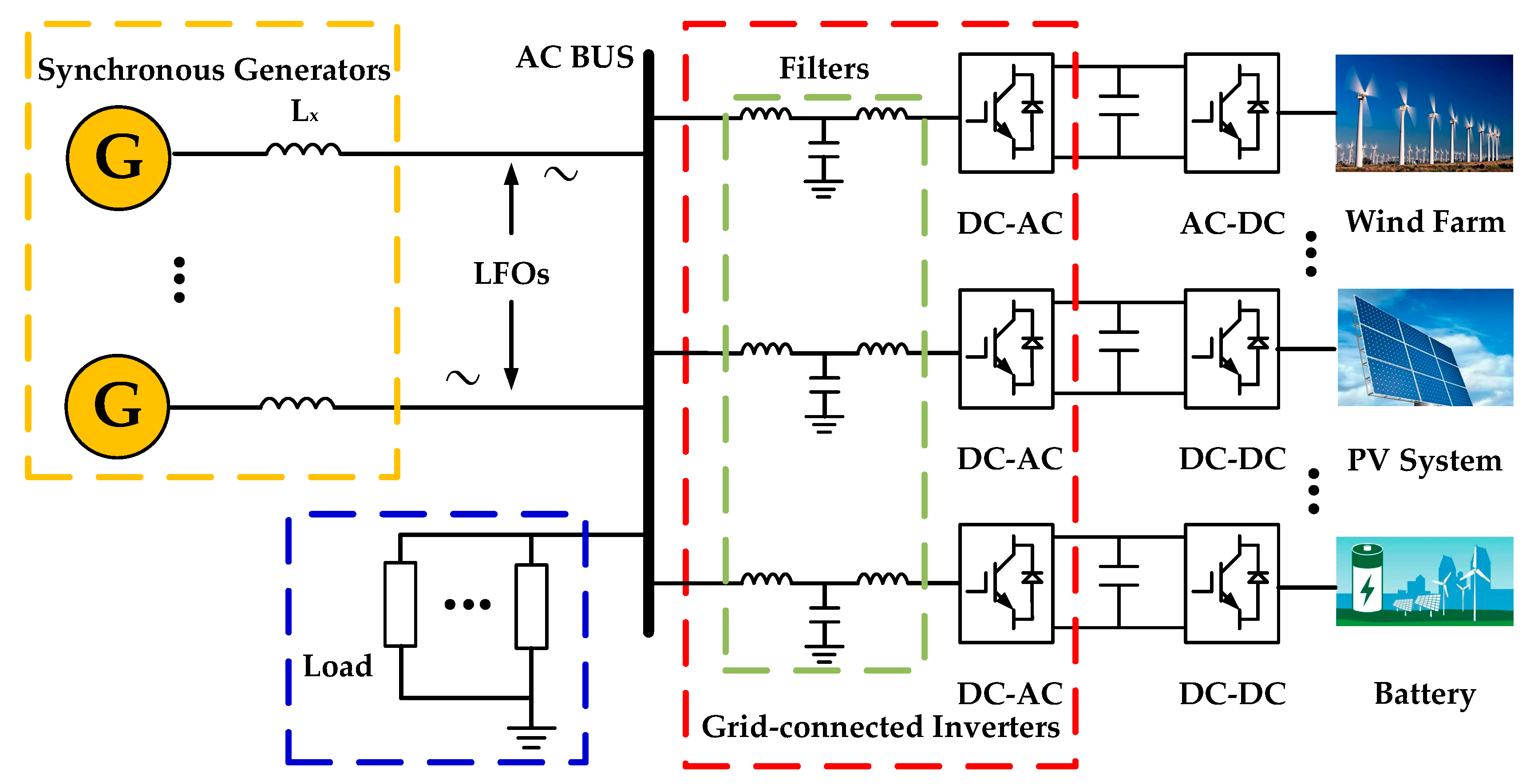
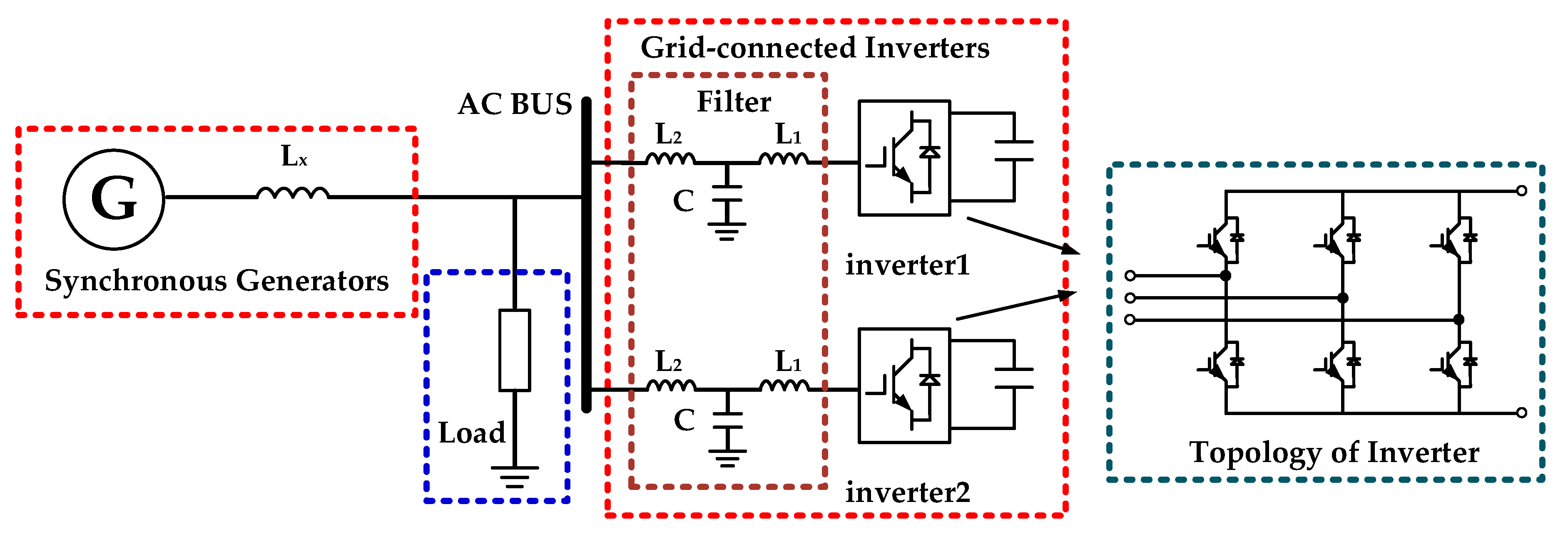
2.1. System Description

Figure 2 depicts the structure of a typical structure of power electronics-based AC power system. The power electronics-based AC power system has synchronous generators and multi inverters. The inverters have a considerable proportion of the transformation and consumption capacity in power grid. The normal control architecture of the inverter controller is shown in Figure 3, where Pref is the d-axis control reference of active power, Udcref is the d-axis control reference of DC voltage, Qref is the q-axis control reference of reactive power, Uacref is the q-axis control reference of AC voltage, i2dref is the d-axis reference current value of inverter, i2qref is the q-axis reference current value of inverter, i2d is the d-axis current value of inverter, i2q is the q-axis current value of inverter, Ucd is the d-axis component of system side voltage, Ucq is the q-axis component of system side voltage, Δvd is the d-axis component variation of inverter side voltage, Δvq is the q-axis component variation of inverter side voltage. Fo(s) is the outer-loop control function of the inverter, F(s) is the inner-loop control function of the inverter.
The multi-inverters shown in Figure 2 can be considered as a controllable voltage source, connecting to the power grid with an LCL filter typically. The multi generators can be equivalent as a voltage source with characteristics of synchronous generator. Figure 4 is the equivalent two-port network of the system shown in Figure 2, where U is the voltage of the generator, V is the voltage of the inverter, xs is the contact inductive reactance, x0 is the inductive reactance of load, r is the resistance of the load, x1 and x2 is the inductive reactance of LCL filter for the inverter and yc is the admittance of LCL filter for the inverter.
The loop circuit equation of two-port network is shown in the following:
( u i ) = ( z 11 z 22 + z 12 z 32 z 11 z 23 + z 12 z 33 z 21 z 22 + z 22 z 32 z 21 z 23 + z 22 z 33 ) ( v i 2 )
where z11, z12, z21, z22 and z′22, z′23, z′32, z′33 are the impedance of two-port networks 1 and 2, respectively, i and i2 are the currents of the line connected with the generator and the inverter, respectively.
Then, the current of the generator in dq synchronous frame is got as:
{ i d = y 1 u d + y 2 u q + y 3 v d + y 4 v q i q = y 5 u d + y 6 u q + y 7 v d + y 8 v q
where y1~y6 represents the correlation impedance, vd is the d-axis component of inverter side voltage, vq is the q-axis component of inverter side voltage, ud is the d-axis voltage of the generator, uq is the q-axis voltage of generator.

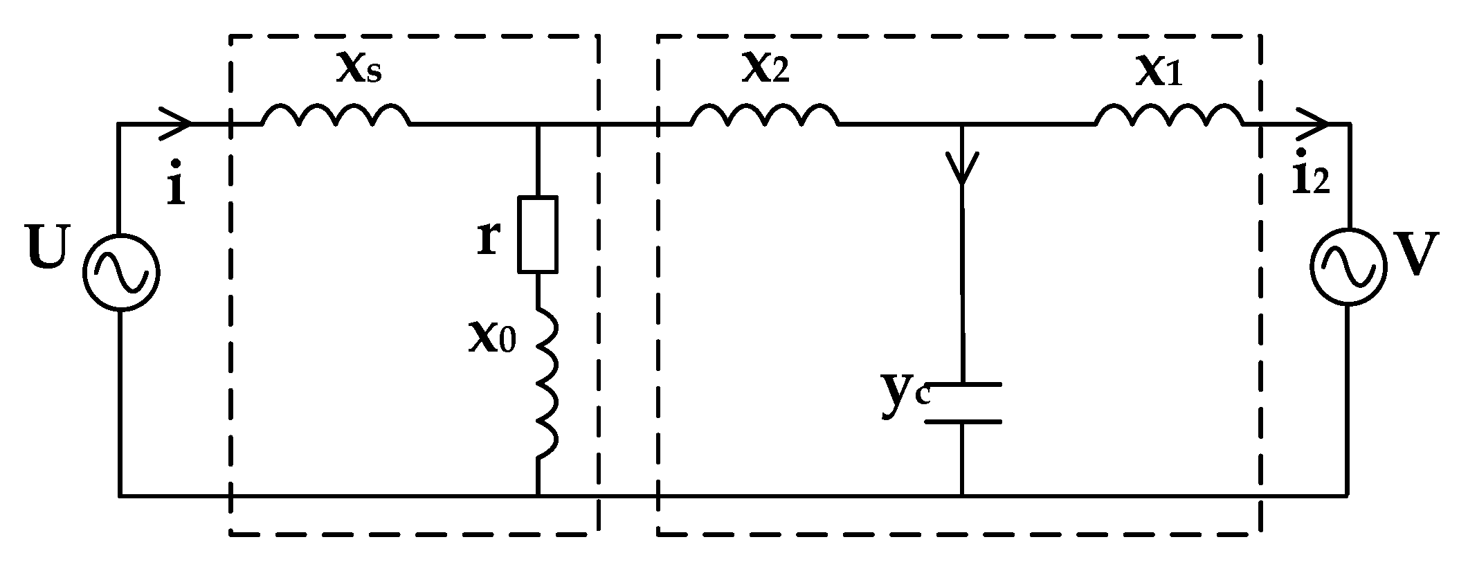
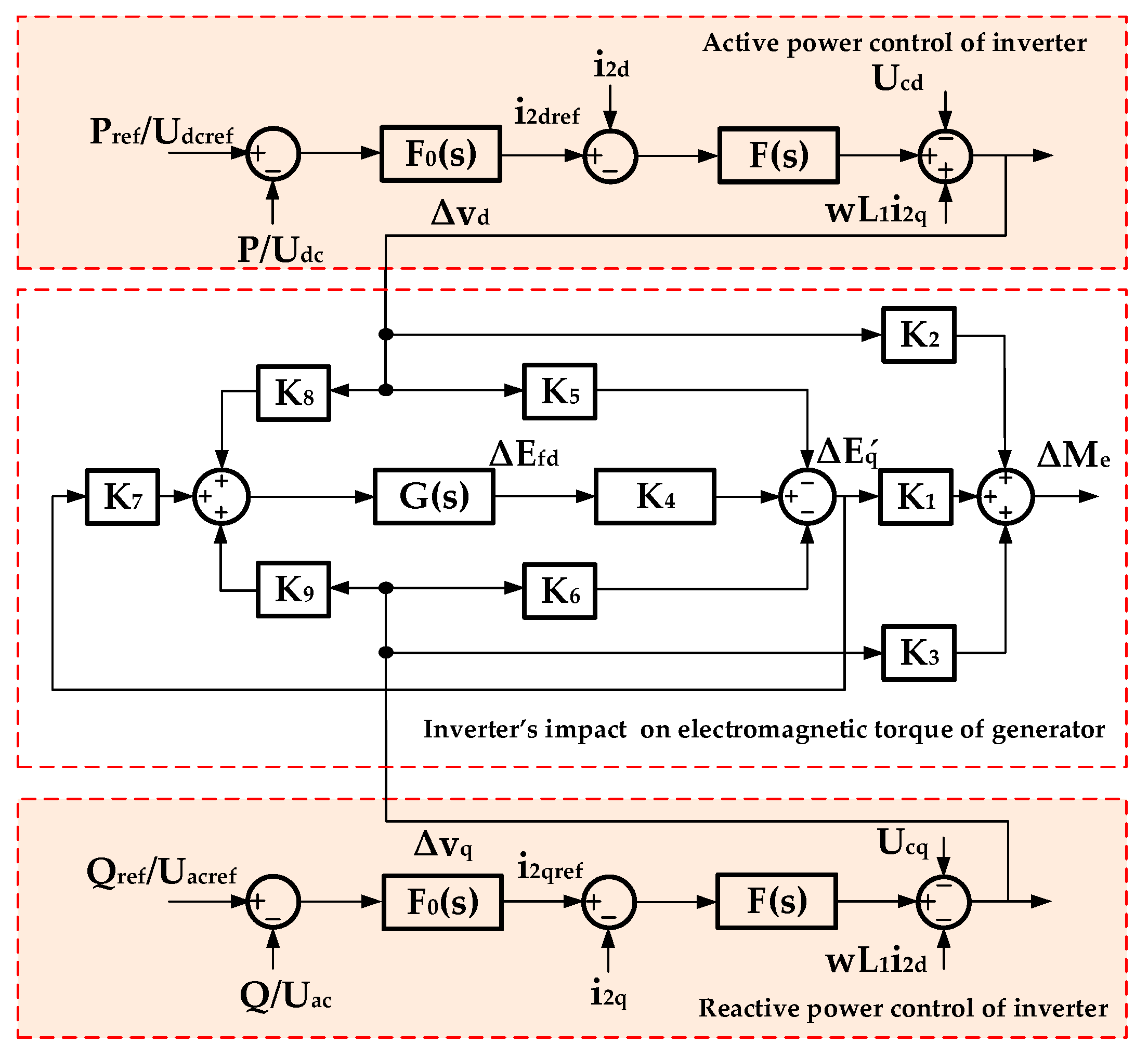
2.2. System Modeling

Through Equation (2), the small-signal model of generator’s current and voltage is derived as shown in Equation (3).
{ Δ u d = x q Δ i q Δ u q = Δ E q x d Δ i d Δ i d = y 1 Δ u d + y 2 Δ u q + y 3 Δ v d + y 4 Δ v q Δ i q = y 5 Δ u d + y 6 Δ u q + y 7 Δ v d + y 8 Δ v q
where x′d is the d-axis transient resistance of the generator, xq is the q-axis resistance of the generator, id is the d-axis current of the generator, id is the q-axis current of generator, ud is the d-axis voltage of the generator, uq is the q-axis voltage of generator, Eq is the internal potential of the generator, Δ represents the micro change of electrical quantities.
The expression of Δid and Δiq could be derived by eliminating Δud and Δuq and illustrated as Equation (4):
{ Δ i d = Z 1 Δ E q + Z 2 Δ v d + Z 3 Δ v q Δ i q = Z 4 Δ E q + Z 5 Δ v d + Z 6 Δ v q
where Z1~Z6 are the admittance coefficient which are derived through Equation (3).
A series equation of electromagnetic relation of the generator is shown as the following Equation (5) [7]:
{ u d = x q i q u q = E q ( x d x d ) i d = E q x d i d M e = u d i d + u q i q = E Q i q E q = E Q ( x q x d ) i d d E q d t = 1 T d 0 ( E f d E q ) u 2 = u d 2 + u q 2
where E′q is a hypothetical potential which is proportional to the flux of excitation system, Me is the electromagnetic torque of the generator, EQ is hypothetical potential behind xq, Efd is the excitation voltage, T’d0 is the time constant of the rotor when the stator is open-circuit.
The small-signal model of the generator is derived as:
{ Δ M e = i q 0 Δ E q + i q 0 ( x q x d ) Δ i d + E Q 0 Δ i q ( 1 + T d 0 s ) Δ E q = Δ E f d ( x q x d ) Δ i d Δ u = u d 0 u 0 x q Δ i q + u q 0 u 0 ( Δ E q x d Δ i d )
where iq0 is the steady-state q-axis current of the generator, ud0 is the steady-state d-axis voltage of the generator, uq0 is the steady-state q-axis voltage of the generator, u0 is the steady-state voltage of the generator, EQ0 is the hypothetical steady-state potential behind xq.
The small-signal model of the synchronous generator with inverter’s voltage is derived in Equation (7) by substituting Equation (4) of Δid and Δiq into Equation (6).
{ Δ M e = K 1 Δ E q + K 2 Δ v d + K 3 Δ v q Δ E q = K 4 Δ E f d K 5 Δ v d K 6 Δ v q Δ u = K 7 Δ E q + K 8 Δ v d + K 9 Δ v q Δ E f d = G ( s ) Δ u { K 1 = i q 0 + i q 0 ( x q x d ) Z 1 E Q 0 Z 4 K 2 = i q 0 ( x q x d ) Z 2 + E Q 0 Z 5 K 3 = i q 0 ( x q x d ) Z 3 + E Q 0 Z 6 { K 4 = 1 1 + ( x q x d ) Z 1 + T d 0 s K 5 = K 4 ( x q x d ) Z 2 K 6 = K 4 ( x q x d ) Z 3 { K 7 = u d 0 u 0 x q Z 4 + u q 0 u 0 u q 0 u 0 x d Z 1 K 8 = u d 0 u 0 x q Z 5 u q 0 u 0 x d Z 2 K 9 = u d 0 u 0 x q Z 6 u q 0 u 0 x d Z 3
G(s) represents the transfer function of the excitation system.
Consider the inverter control shown in Figure 3, the block diagram of the small-signal control model of the generator-inverter system can be obtained from the above analysis as Figure 5.
According to the control block diagram and the superposition principle, the transfer functions of ΔMeVd and ΔMe/ΔVq are obtained, respectively:
{ Δ M e Δ v d = ( K 1 K 8 K 2 K 7 ) G K 4 K 1 K 5 + K 2 1 K 7 G K 4 Δ M e Δ v q = ( K 1 K 9 K 3 K 7 ) G K 4 K 1 K 6 + K 3 1 K 7 G K 4 G ( s ) = k i + k p s s
where ki is the integral time constant, kp is the proportion coefficient.
The phase and amplitude difference between the output of the grid-connect inverter and the electromagnetic torque of the synchronous generator can be calculated by Equation (8). In this chapter, the small-signal model of the impact of the grid-connected inverter on electromagnetic torque of synchronous generator in power electronics-based AC power system has been deduced. The model reveals the relationship between the output power of the inverter and the generator torque. The model is the analysis basis of using the grid-connected inverter to increase low frequency damping.
According to the classical power system theory, a torque can be decomposed into two components, i.e., damping torque and synchronizing torque. The positive direction of the damping torque is in phase with the angular frequency Δω. The positive direction of the synchronizing torque is in phase with the angle Δδ. The influence of normal control grid-connected inverter on low frequency damping mainly depends on the Δω direction component of electromagnetic torque.
According to the Heffron-Philips model, the relationship between terminal voltage and power angle can be present as Equation (9).
{ Δ u = K 5 H P Δ δ + K 6 H P Δ E q K 5 H P = u d 0 u 0 x q x q + x l U L cos δ 0 u q 0 u 0 x d x d + x l U L sin δ 0 K 6 H P = u q 0 u 0 x l x d + x l
where ∆δ is the power angle deviation, K5H-P is the factor of ∆δ in the Heffron-Philips model, K6H-P is the factor of ∆Eq΄ in Heffron-Philips model, xl is the line impedance and UL is the voltage behind line impedance xl.
According to Equation (9), ∆u occurs when there is a disturbance of power angle. The variation of the active power of grid-connect inverter ΔP can be assumed to follow ∆u. Moreover, the regulation of active power in the inverter is in the opposite direction of active power measurement variation. After a series of PI control, the phase of ΔMe produced by grid-connect inverter lags the phase of -∆u. So, the torque phasor diagram under oscillation can be shown in Figure 6, where Δu is the component related to power angle, ΔMeD is the damping torque component of ΔMe, ΔMeS is the synchronizing torque component of ΔMe, θM represents the phase difference from the phase of -Δu to the phase of ΔMe. From Figure 6, it can be seen that the damping torque component of ΔMe is negative. The negative damping reduces the damping of the system and makes it easier for the appearance of LFOs.

3. LFOs Suppression Strategy Using Inverter with Built-In PSS

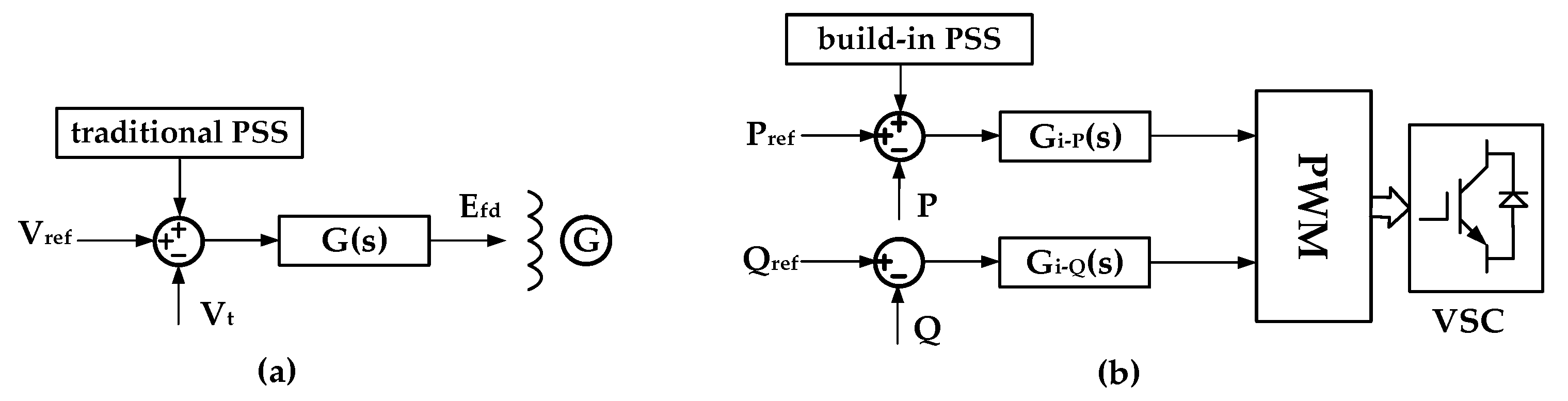
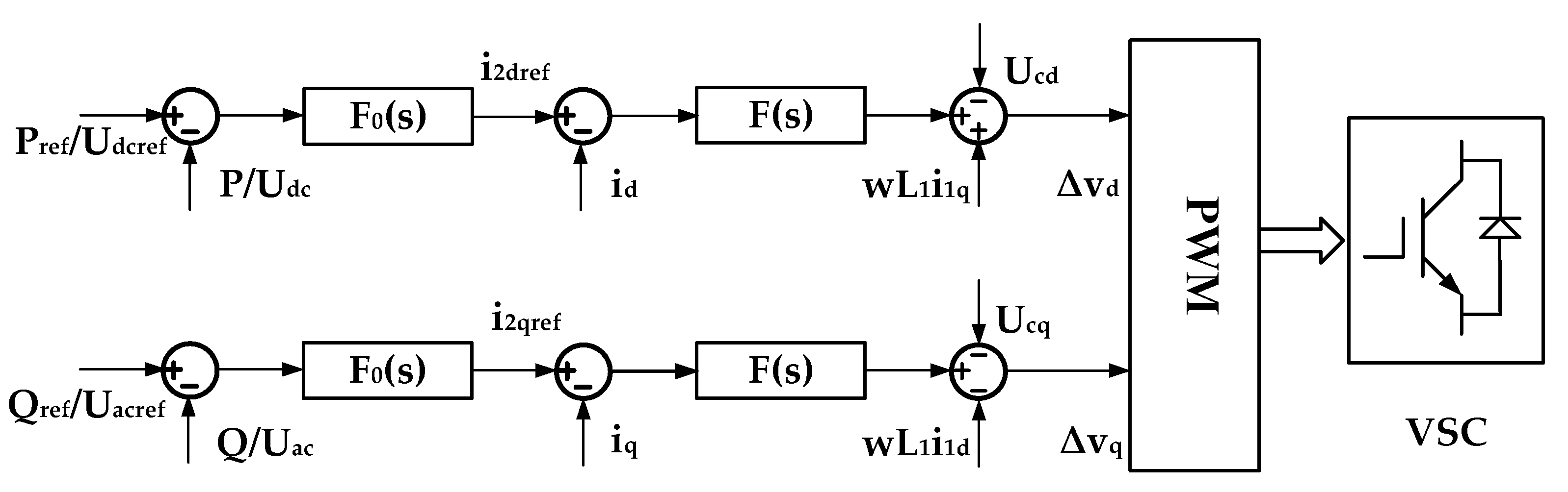
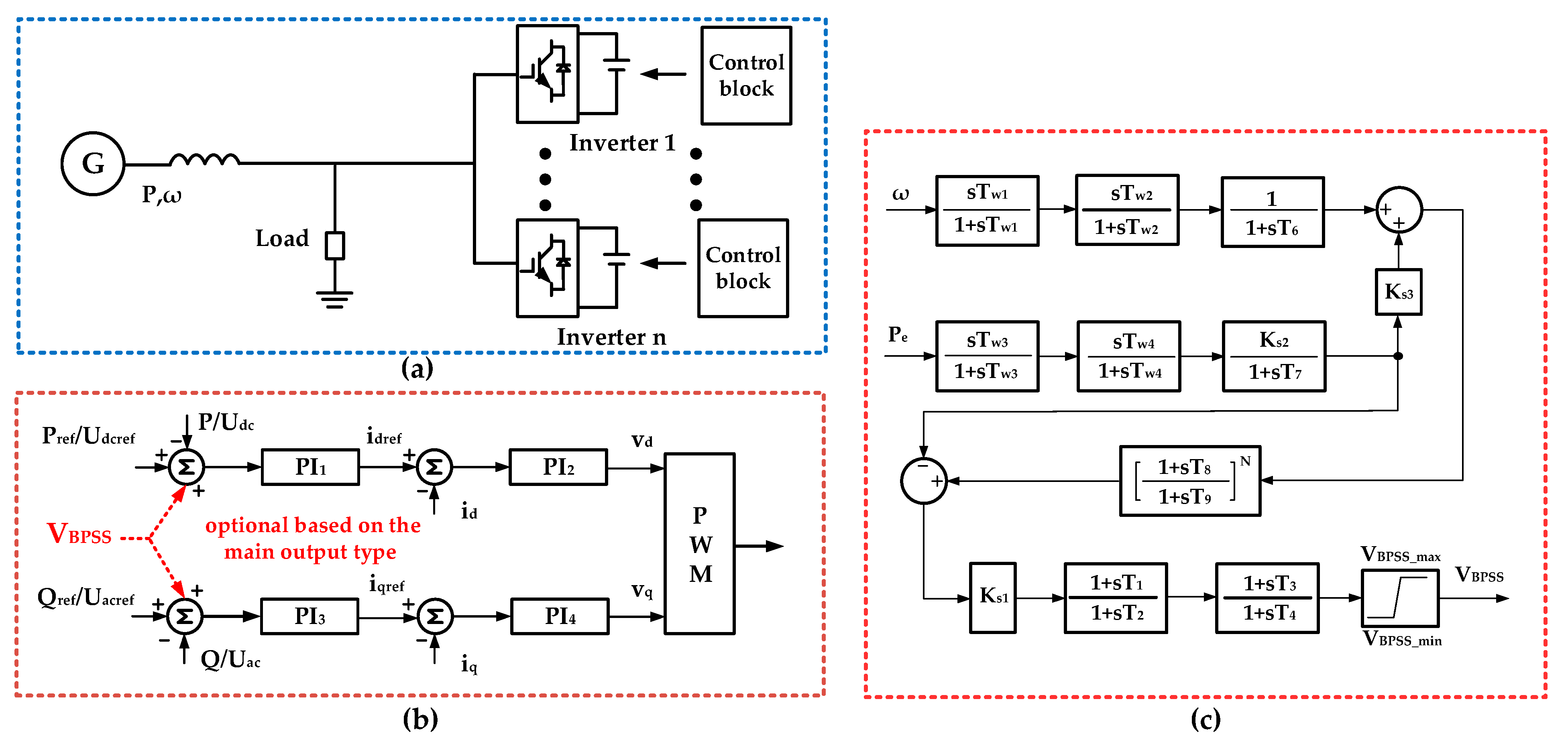
3.1. The Control Structure of the Inverte with Built-In PSS

In order to increase low frequency damping, the grid-connected inverter needs to increase the torque in the positive direction of the axis Δω to increase the damping torque. An extra torque ΔT can be introduced to provide positive synchronizing torque in the frequency range of LFOs. From Figure 4 and Equation (8), an additional control that passes the lead-lag correction component and inverter control loop can be introduced into the control loop of the grid-connected inverter to make the inverter produce positive damping torque.
To introduce the positive direction of the axis Δω, the active power or electric angular velocity on the interconnection line can be taken as the input of the additional control. Active power or angular velocity signal is introduced into the grid-connected inverter to produce positive damping, which is similar to the purpose of installing PSS on the excitation system. So, the additional control in the grid-connected inverter can use the experience of the structure of PSS to restrain LFOs. The grid-connected inverter is not willing to produce additional torque due to the normal power regulation of the generator, which will affect its output capacity. Regarding the control structure of PSS2B, the acceleration power is used as the input signal. After the acceleration power input signal passes through a series of lead-lag components, the output phase is corrected to produce positive damping to suppress LFOs.
The built-in PSS structure for grid-connected inverter and application in the system is shown in Figure 7, where Pref is the d-axis control reference of active power, Udcref is the d-axis control reference of DC voltage, Qref is the q-axis control reference of reactive power, Uacref is the q-axis control reference of AC voltage. ω and Pe is the input signal, TW1 is the time constant of the first DC block component for input signal ω, TW2 is the time constant of the second DC block of input signal ω, TW3 is the time constant of the first DC block of input signal Pe, TW4 is the time constant of the second DC block for input signal Pe, KS2 is the gain coefficient of the integral component for input signal Pe, KS3 is a composite coefficient, T6 is the time constant of the integral component for input signal Pe, KS1 is gain coefficient of regulating component, T1 is the lead time constant of first lead-lag component, T2 is the lead time constant of first lead-lag component, T3 is the lead time constant of second lead-lag component, T4 is the lag time constant of second lead-lag component, VBPSS is the output of PSS for grid-connected inverter, VBPSS_max is the upper limit of VBPSS, VBPSS_min is the lower limit of VBPSS. VBPSS is superimposed on the control target of the grid-connected inverter.
The additional electromagnetic torque is realized through the output of built-in PSS. The output of built-in PSS can be added with the reference of active power or reactive power in the control of grid-connected inverter. The superposition position is shown in Figure 7b, where The Pref/Udcref or Qref/Uacref in Figure 7b can be selected as the superimposed point according to the actual needs. When the grid-connected inverter output mainly active power, the built-in PSS shall be superposed on the corresponding active power control loop. When the grid-connected inverter output mainly reactive power, the built-in PSS shall be superposed on the corresponding reactive power control loop. The inverter damping torque control realized through active power control is different from the damping control of PSS realized through reactive power control of the generator.

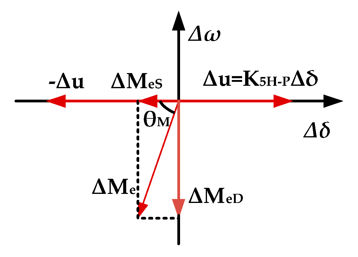
3.2. Parameters Design Guidline for Built-In PSS

Different introduced extra torques have different damping effect. The angle between extra torque ΔT and Δω axis and the amplitude of ΔT are the main factor determining damping torque. For the parameter tuning of built-in PSS, the lead-lag component parameters mainly determine the angle and Ks1 determines the amplitude.
Undamped natural oscillation angular velocity is taken as the compensation point. The phase which the additional torque generated by built-in PSS lag to the input of the lead-lag components can be calculated through Equation (8). Then the parameters of the lead-lag components can be set according to the phase compensation demand. The other parameters of the filters in built-in PSS can use the design method of PSS which is used in excitation system.
As illustrated above, built-in PSS is superimposed on the reference of the outer-loop control. The additional control torque of built-in PSS has passed the control function Fo(s) and F(s). Then, the whole transfer function of additional torque of built-in PSS to electromagnetic torque of generator is shown as Equation (10).
{ Δ M e Δ ω i P S S = Δ M e Δ v d F o ( s ) F ( s ) F 0 ( s ) = k p o + k i o / s F ( s ) = k p i + k i i / s
where kpo is the proportion coefficient of the outer-loop control, kio is the integral time constant of the outer-loop control, kpi is the proportion coefficient of the inner-loop control, kii is the integral time constant of the inner-loop control.
According to the Heffron-Philips model, the undamped mechanical nature angular velocity of the rotor can be obtained through Equation (11).
{ ω n = K 1 H P ω 0 / T J K 1 H P = x q x d x d + x s i q 0 u sin δ 0 + u cos δ 0 x q + x s E Q 0
where ωn is the undamped mechanical nature angular velocity of the rotor, Δ0 is the steady value of generator power-angle, ω0 is the rated angular velocity, and TJ is the inertia constant of the generator.
When ωn has been calculated, the phase of the whole system at the undamped mechanical nature angular velocity can be obtained through Equation (11). In order to produce positive damping torque and synchronous torque, the phase of additional damping torque should lead Δω with phase 0~40 degrees. Then, compensatory angle ϕx of the lead-lag component of built-in PSS can be deduced.
The two lead-lag components of built-in PSS can adopt the same parameters. Then, T1 is equal to T3, T2 is equal to T4. As the inverter regulars very fast, the lag time constant T2 is required to correspond with the speed. So, T2 can be determined by reference to the regular time of inverter. The value of T1 can be obtained according to the requirement of compensatory angle ϕx through Equation (12) as follow.
ϕ x / 2 = arctan T 1 ω n arctan T 2 ω n
When lead-lag component parameters are determined, KS1 can be determined by the critical gain method. The equivalent amplification factor of built-in PSS can be defined as AP, and its calculation formula is shown as Equation (13).
A P = K s 1 1 + T 1 2 1 + T 2 2

4. Verification

The classic step test of the generator terminal voltage is used to test low frequency damping. 5% step test of the generator terminal voltage is used in simulation and 3% step test of the generator terminal voltage is used in experiment. The damping effect of the built-in PSS can be observed in the process of the oscillation. The built-in PSS is a control for damping torque. So, the damping mechanism for multi-inverters with built-in PSS is same with the single inverter with built-in PSS. The simulation includes two parts. One part is about the different damping effects of different parameters of the built-in PSS. The other part is about the damping effects of dual paralleled grid-connected inverters with different built-in PSS situations. The experiment of generator-inverter system is also carried out to verify the damping control effect of the built-in PSS. The oscillation waveforms with and without built-in PSS in setting conditions are compared. The inverter can produce corresponding power oscillation which suppress the transmission power oscillation. The correctness of the analysis above is verified by the simulation and experimental result.

4.1. System Description and Setting

Simulation results based on PSCAD are provided to verify the analysis of built-in PSS. The simulation and experimental set up of a simplified power electronics-based AC power system is established as Figure 8. The two simulation parts uses single inverter and two paralleled inverters, respectively. The part with one inverter is used to verify the damping effects with different built-in PSS parameters. The part with two inverters is used to verify the damping effect of multi-inverters. The main parameters are shown in Table 1. The voltage of DC source is set as 400 V.

4.2. Parameters Design

To make T1~T4 positive, the output of built-in PSS is multiplied by −1 before adding to the reference value of active power control in this simulation, which results in a phase shift of 180°. According to the parameters of circuit and control function, the phase of ΔMe lags the phase of ΔωBPSS about 0~90° in the frequency range of LFOs.
The output of built-in PSS is added with the output of d-axis control. The Pref and Qref of the grid-connected inverter are set to be 0.4 MW and 0 MVar. According to the parameters of circuit and control function, ωn can be calculated as 11.04 rad/s. From Figure 9 the phase of ΔMe/ΔωBPSS at ωn can be got as 75.1°.
Achieving ΔωBPSS leading ΔMe with 30°, this paper set compensatory angle ϕx of the lead-lag component of built-in PSS as 75°. According to the regulation time of the inverter, 0.01 can be taken as T2 value. T1 value can be derived through Equation (12). The parameters of built-in PSS are shown in Table 2. For see more details of the influence of built-in PSS, the limited output of built-in PSS is set quite lager as 20% of Pref. In the actual project, the limit value should be according to the capacity of the inverter.
The bode diagram of ΔMe/ΔωBPSS with and without compensation is shown in Figure 9. From the bode diagram, ΔωBPSS leads ΔMe 30 degree at the target frequency of LFOs. As the Δω relevance vector is used as input, the phase of additional torque is 30 degrees lead of Δω axis.

4.3. Damping Effects of Single Grid-Connected Inverter with Different Parameters

Case I is the situation that damping torques have same ϕx with different AP. Case II is the situation that damping torques have same AP with different ϕx. The simulation results are shown in Figure 10.
In case I compensatory angle ϕx of lead-lag component of built-in PSS is fixed as 75°, the damping torque diagram with different AP is shown in Figure 10a, where TBPSS0 is the damping torque of built-in PSS without phase compensation, TBPSS1 is the damping torque when Ks1 = 7.98, TBPSS2 is the damping torque when Ks1 = 6, TBPSS3 is the damping torque when Ks1 = 4.
In case II AP of built-in PSS is fixed as 8.04, the damping torque diagram with different ϕx is shown in Figure 10a. Where TBPSS0 is the damping torque of built-in PSS without phase compensation, TBPSS1 is the damping torque when ϕx =65°, TBPSS2 is the damping torque when ϕx =75°, TBPSS3 is the damping torque when ϕx = 85°. Figure 10b shows the active power of generator in both cases; Figure 10c shows output of built-in PSS with various ϕx and AP; Figure 10d shows active power of grid-connected inverter in both cases; Figure 10e shows reactive power of grid-connected inverter in both cases; Figure 10f shows terminal voltage of generator in both cases.
For case I, from Figure 10b it can be seen that the bigger AP could produce lager positive damping torque. For case II, from Figure 10b the closer to the Δω-axis could produce a lager positive damping torque. From Figure 10c,d it can be seen that larger output of the built-in PSS corresponds larger power fluctuation of inverter and lager positive damping torque. With the appropriate setting of KS1 and ϕx, the system damping can be increased. Under the action of built-in PSS, the active power fluctuation of inverter provides positive damping to the system. The verification results are consistent with the above theoretical analysis. Meanwhile, from Figure 10e,f, the damping regulation has little influence on terminal voltage of generator. The reason for that is that the built-in PSS in inverter is added to the active power control and the inverter adopts active and reactive power decoupling control strategy.

4.4. Damping Effects of Dual Paralleled Grid-Connected Inverters

More capacity of inverters to influence the electromagnetic torque of generator can present more damping effect. In this paper the situation of two inverters is taken as an example of multi-inverters connected with synchronous generator.
When the load is fixed, the different numbers of grid-connected inverters is set to realize the different distribution of active power between the inverter and the generator in the system shown in Figure 8. Figure 11 is the simulation result of two parallel grid-connected inverters system with different built-in PSS situations. The Pref of the grid-connected inverter are set to be 0.4 MW and 0.2 MW, respectively. The Qref of the grid-connected inverter are set to be 0 MVar. The built-in PSS in both inverters adopts Ks1 = 6 and same value as shown in Table 2 for the other parameters.
Three built-in PSS situations are simulated, case I: none of the inverters has built-in PSS; case II: only the larger output inverter has built-in PSS; case III: both of the inverters have built-in PSS. Figure 11a shows the fluctuation comparison of generator’s active power under the three cases. From the figure it can be seen that better damping effect can be get by more inverters with built-in PSS. Figure 11b shows the active power of the larger output inverter under the three cases. Figure 11c shows the active power of the lower output inverter under the three cases. Figure 11d shows the output of built-in PSS in the inverters under the three cases. From Figure 11b–d, the active power fluctuation of the larger inverter can be reduced when two inverters have damping effect. The increasing of low frequency damping reduces the output of the built-in PSS of the inverter.

4.5. Experimental Results

The experimental platform is consisted of one synchronous generator, two inverters and resistances. The structure of the system is same with the simulation system structure as shown in Figure 8. The experimental platform is shown in Figure 12. The parameters of the experimental platform are shown in Table 3. The two inverters all adopt same control and built-in PSS. The excitation system and the inverters use the same control parameters as shown in Table 1.
The parameters of built-in PSS are designed as the analysis above and shown in Table 4.
Three percent step of the generator terminal voltage test is used as the test condition. The active power waveforms of the generator under the system with and without built-in PSS are shown in Figure 13. To illustrate the damping effect of the built-in PSS with different parameters, the waveform of with built-in PSS 1 uses the parameters in Table 4 and the waveform of with built-in PSS 2 adopts the parameters in Table 4 except T1 = T3 = 0.16, Ks1 = 7.3. The data of active power is recorded by controller of the inverter. The active power waveforms are obtained by using data processing software to process the recorded data. From the comparison, the inverters with built-in PSS can increase the low frequency damping. The low frequency damping can be controlled through the adjusting of the parameters. The result is consistent with theoretical analysis above.
The oscillation information can be obtained through the input signals of the transmission active power and angular velocity. The lead-lag component compensates the phase shift caused by the power electronics-based AC grid. That makes the inverter can provide the corresponding active power variation to suppress the oscillation. The simulation and experimental result illustrate that the built-in PSS could increase low frequency damping with the proposed parameters design. The simulation and experimental results are consistent with the above theoretical analysis. The analysis is also suitable for multi parallel grid-connected inverters system in the power grid with synchronous generator characteristics.

5. Conclusions

Under the new situation that larger scale power electronics equipment and synchronous generator coexist in the power grid, making inverter participate in low frequency damping control is the key to enhancing system stability. In this paper, the low frequency damping control for power electronics-based AC power system using inverters with built-in PSS is analyzed. The model of the impact of the grid-connected inverter on the electromagnetic torque of the synchronous generator is researched and proposed. The model is the basis of increasing accurate positive low frequency damping torque through the grid-connected inverter. The built-in PSS of the inverter is used to introduce additional positive damping torque for the system. The structure of the built-in PSS is illustrated. Angular velocity and active power are used as input signals. Through lead-lag components, the built-in PSS makes inverter generate positive damping torque to increase low frequency damping. The built-in PSS control can be superposition to active power control or reactive power control loop of the inverter. The design method for the main parameter of built-in PSS is also proposed. Finally, the correctness of the theoretical analysis and the effectiveness of the built-in PSS is verified by the simulation and experiment.

Author Contributions

Conceptualization, W.C. and M.Y.; Data curation, M.Y.; Funding acquisition, J.Z.; Methodology, M.Y. and T.L.; Software, T.L.; Validation, W.L.; Writing—original draft, M.Y. and T.L.; Writing—review & editing, W.C. and M.Y. All authors have read and agreed to the published version of the manuscript.

Funding

This research was supported in part by the National Natural Science Foundation of China (Grant Number 51877042).

Institutional Review Board Statement

Not applicable.

Informed Consent Statement

Not applicable.

Data Availability Statement

Not applicable.

Conflicts of Interest

The authors declare no conflict of interest.

References

  1. Chompoobutrgool, Y.; Ghandhari, M.; Vanfretti, L. Survey on power system stabilizers control and their prospective applications for power system damping using synchrophasor-based wide-area systems. Eur. Trans. Electr. Power 2011, 21, 2098–2111. [Google Scholar] [CrossRef] [Green Version]
  2. Pogaku, N.; Prodanovic, M.; Green, T.C. Modeling, analysis and testing of autonomous operation of an inverter-based microgrid. IEEE Trans. Power Electron. 2007, 22, 613–625. [Google Scholar] [CrossRef] [Green Version]
  3. Qi, J.; Wu, Q.; Zhang, Y.; Weng, G.; Zhou, D. Unified residue method for design of compact wide-area damping controller based on power system stabilizer. J. Mod. Power Syst. Clean Energy 2020, 8, 366–375. [Google Scholar] [CrossRef]
  4. Zhong, Q.; Weiss, G. Synchronverters: Inverters that mimic synchronous generators. IEEE Trans. Ind. Electron. 2011, 58, 1259–1267. [Google Scholar] [CrossRef]
  5. Alipoor, J.; Miura, Y.; Ise, T. Stability assessment and optimization methods for microgrid with multiple VSG units. IEEE Trans. Smart Grid 2018, 9, 1462–1471. [Google Scholar] [CrossRef]
  6. Jiang, Q.; Li, B.; Liu, T. Large-scale power base’s impact on low frequency oscillation characteristic in UHVAC power transmission system. IEEE Access 2019, 7, 56423–56430. [Google Scholar] [CrossRef]
  7. Kundur, P. Power System Stability and Control; McGraw-Hill: New York, NY, USA, 1994. [Google Scholar]
  8. Zhou, J.; Shi, P.; Gan, D.; Xu, Y.; Xin, H.; Jiang, C.; Xie, H.; Wu, T. Large-scale power system robust stability analysis based on value set approach. IEEE Trans. Power Syst. 2017, 32, 4012–4023. [Google Scholar] [CrossRef]
  9. Chen, H.; Yu, W.; Liu, Z.; Yan, Q.; Tasiu, I.A.; Han, Z. Low-frequency instability induced by hopf bifurcation in a single-phase converter connected to non-ideal power grid. IEEE Access 2020, 8, 62871–62882. [Google Scholar] [CrossRef]
  10. Zhou, J.; Ke, D.; Chung, C.Y.; Sun, Y. A computationally efficient method to design probabilistically robust wide-area PSSs for damping inter-area oscillations in wind-integrated power systems. IEEE Trans. Power Syst. 2018, 33, 5692–5703. [Google Scholar] [CrossRef]
  11. Xiong, L.; Zhuo, F.; Wang, F.; Liu, X.; Chen, Y.; Zhu, M.; Yi, H. Static synchronous generator model: A new perspective to investigate dynamic characteristics and stability issues of grid-tied PWM inverter. IEEE Trans Power Electron. 2016, 31, 6264–6280. [Google Scholar] [CrossRef]
  12. Yao, W.; Jiang, L.; Wen, J.; Wu, Q.H.; Cheng, S. Wide-area damping controller of FACTS devices for inter-area oscillations considering communication time delays. IEEE Trans. Power Syst. 2014, 29, 318–329. [Google Scholar] [CrossRef] [Green Version]
  13. Zhang, C.; Ke, D.; Sun, Y.; Chung, C.Y.; Xu, J.; Shen, F. Coordinated supplementary damping control of DFIG and PSS to suppress interarea oscillations with optimally controlled plant dynamics. IEEE Trans. Sustain. Energy 2018, 9, 780–791. [Google Scholar] [CrossRef]
  14. D’Arco, S.; Suul, J.A. Equivalence of virtual synchronous machines and frequency-droops for converter-based microgrids. IEEE Trans. Smart Grid. 2014, 5, 394–395. [Google Scholar] [CrossRef]
  15. Wen, B.; Boroyevich, D.; Burgos, R.; Mattavelli, P.; Shen, Z. Small signal stability analysis of three-phase AC systems in the presence of constant power loads based on measured D-Q frame impedances. IEEE Trans. Power Electron. 2015, 30, 5952–5963. [Google Scholar] [CrossRef]
  16. Amin, M.; Molinas, M. Small-signal stability assessment of power electronics based power systems: A discussion of impedance- and eigenvalue-based methods. IEEE Trans. Ind. Appl. 2017, 53, 5014–5030. [Google Scholar] [CrossRef]
  17. Wen, B.; Boroyevich, D.; Burgos, R.; Mattavelli, P.; Shen, Z. Analysis of D-Q small-signal impedance of grid-tied inverters. IEEE Trans. Power Electron. 2016, 31, 675–686. [Google Scholar] [CrossRef]
  18. Ashabani, M.; Mohamed, Y.A.R.I. Mohamed. Integrating VSCs to weak grids by nonlinear power damping controller with self-synchronization capability. IEEE Trans. Power Syst. 2014, 29, 805–813. [Google Scholar] [CrossRef]
  19. Kalcon, G.O.; Adam, G.P.; Anaya-Lara, O.; Lo, S.; Uhlen, K. Small-signal stability analysis of multi-terminal VSC-based DC transmission systems. IEEE Trans. Power Syst. 2012, 27, 1818–1830. [Google Scholar] [CrossRef]
  20. Hassan, L.H.; Moghavvemi, M.; Almurib, H.A.; Muttaqi, K.M. A coordinated design of PSSs and UPFC-based stabilizer using genetic algorithm. IEEE Trans. Ind. Appl. 2014, 50, 2957–2966. [Google Scholar] [CrossRef]
  21. Zhang, K.; Shi, Z.; Huang, Y.; Qiu, C.; Yang, S. SVC damping controller design based on novel modified fruit fly optimization algorithm. IET Renew. Power Gener. 2017, 12, 90–97. [Google Scholar] [CrossRef]
  22. Zuo, J.; Li, Y.; Shi, D.; Duan, X. Simultaneous robust coordinated damping control of power system stabilizers (PSSs), static var compensator (SVC) and doubly-fed induction generator power oscillation dampers (DFIG PODs) in multi machine power systems. Energies 2017, 10, 565–588. [Google Scholar]
  23. Ahmed, M.; Vahidnia, A.; Datta, M.; Meegahapola, A. An adaptive power oscillation damping controller for a hybrid AC/DC microgrid. IEEE Access 2020, 8, 69482–69495. [Google Scholar] [CrossRef]
  24. Kerdphol, T.; Waranabe, M.; Hongesombut, K.; Mitani, Y. Self-adaptive virtual inertia control-based fuzzy logic to improve frequency stability of microgrid with high renewable penetration. IEEE Access 2019, 7, 76071–76083. [Google Scholar] [CrossRef]
  25. Zhou, Y.; Liu, J.; Li, Y.; Gan, C.; Li, H.; Liu, Y. A gain scheduling wide-area damping controller for the efficient integration of photovoltaic plant. IEEE Trans. Power Syst. 2019, 34, 1703–1715. [Google Scholar] [CrossRef]
  26. Wan, C.; Huang, M.; Tse, C.K.; Ruan, X. Effects of interaction of power converters coupled via power grid: A design-oriented study. IEEE Trans. Power Electron. 2015, 30, 3589–3600. [Google Scholar] [CrossRef]
  27. Liu, J.; Miura, Y.; Ise, T. Comparison of dynamic characteristics between virtual synchronous generator and droop control in inverter based distributed generators. IEEE Trans. Power Electron. 2016, 31, 3600–3611. [Google Scholar] [CrossRef]
  28. Huang, L.; Xin, H.; Wang, Z. Damping low-frequency oscillations through VSC-HVDC stations operated as virtual synchronous machines. IEEE Trans. Power Electron. 2018, 34, 5803–5818. [Google Scholar] [CrossRef]
  29. Faraji, A.; Naghshbandy, A.H.; Baayeh, A.G. A hybrid coordinated design method for power system stabilizer and FACTS device based on synchro squeezed wavelet transform and stochastic subspace identification. J. Mod. Power Syst. Clean Energy 2020, 1–10. [Google Scholar] [CrossRef]
Figure 1. Traditional PSS in excitation system and the proposed built-in PSS in inverter. (a) Traditional PSS in excitation system; (b) the proposed built-in PSS in inverter.
Energies 14 02435 g001
Figure 2. A typical set up of power electronics-based AC power system.
Energies 14 02435 g002
Figure 3. The typical control structure of the inverter.
Energies 14 02435 g003
Figure 4. Two-port network for simplified power electronics-based AC power system.
Energies 14 02435 g004
Figure 5. The small-signal model of the inverter output and the generator electromagnetic torque.
Energies 14 02435 g005
Figure 6. Torque phasor diagram during oscillation.
Energies 14 02435 g006
Figure 7. PSS control structure for grid-connected inverter and application in the system. (a) System structure; (b) superposition point of PSS output in the inverter control; (c) PSS control structure.
Energies 14 02435 g007
Figure 8. Simulation and experimental set up on PSCAD.
Energies 14 02435 g008
Figure 9. The bode diagram of ΔMe/ΔωBPSS with and without compensation.
Energies 14 02435 g009
Figure 10. Simulation results of same ϕx with different AP (case I), same AP with different ϕx (case II). (a) Schematic diagram of damping torque with different AP and ϕx; (b) active power of generator; (c) output of built-in PSS with various ϕx and AP; (d) active power of grid-connected inverter; (e) reactive power of grid-connected inverter; (f) terminal voltage of generator.
Energies 14 02435 g010
Figure 11. Simulation results of two parallel grid-connected inverters system with different built-in PSS situations, case I: none of the inverters has built-in PSS; case II: only the larger output inverter has built-in PSS; case III: both of the inverters have built-in PSS. (a) Active power fluctuation comparison of generator under the three cases; (b) active power of the larger output inverter under the three cases; (c) active power of the lower output inverter under the three cases; (d) output of built-in PSS in the inverters under the three cases.
Energies 14 02435 g011
Figure 12. Experiment platform. (a) Synchronous generator; (b) inverter; (c) controller of the inverter.
Energies 14 02435 g012
Figure 13. Active power waveform of the generator under the system with and without built-in PSS.
Energies 14 02435 g013
Table 1. Main parameters for simplified power electronics-based AC power system.
ParametersValues
system impedanceLs0.1 mH
loadr0.082 Ω
L00.082 mH
DC sourceVdc400 V
Generatorx′d0.0361 Ω
xq0.2238 Ω
T′d03.55
id01093.7 A
iq01803.7 A
ud0285.6726 V
uq0117.17 V
u0308.77 V
EQ0361.96 V
Sbase1 MVA
Utbase20 kV
excitation system controlkp100
ki60
LCL filterL10.2 mH
L20.04 mH
C15 uF
Inverter control Fo(s)kpo4
kio20
Inverter control F(s)kpi4
kii100
Table 2. Parameters of built-in PSS of inverter.
Tw1Tw2Tw3Tw4T6T7M
22220105
NKs2Ks3T8T9T1T2
13.210.20.050.08680.01
T3T4Ks1VBPSS_maxVBPSS_max
0.08680.017.980.08 MW−0.08 MW
Table 3. The parameters of the experimental platform.
ParametersValues
GeneratorSbase30 kVA
Utbase400 V
x’d0.3556 pu
xq1.0825 pu
T’d06.55
LCL filterL10.2 mH
L20.04 mH
C15 uF
loadr2.4 Ω
DC sourceVdc400 V
Table 4. Parameters of built-in PSS of inverter for experiment.
Tw1Tw2Tw3Tw4T6T7M
22220105
NKs2Ks3T8T9T1T2
13.210.20.050.150.01
T3T4Ks1VBPSS_maxVBPSS_max
0.150.016.30.9 kW−0.9 kW
Publisher’s Note: MDPI stays neutral with regard to jurisdictional claims in published maps and institutional affiliations.

