
Investigating the Converter-Driven Stability of an Offshore HVDC System

 , , ,
, , ,
Abstract
1. Introduction
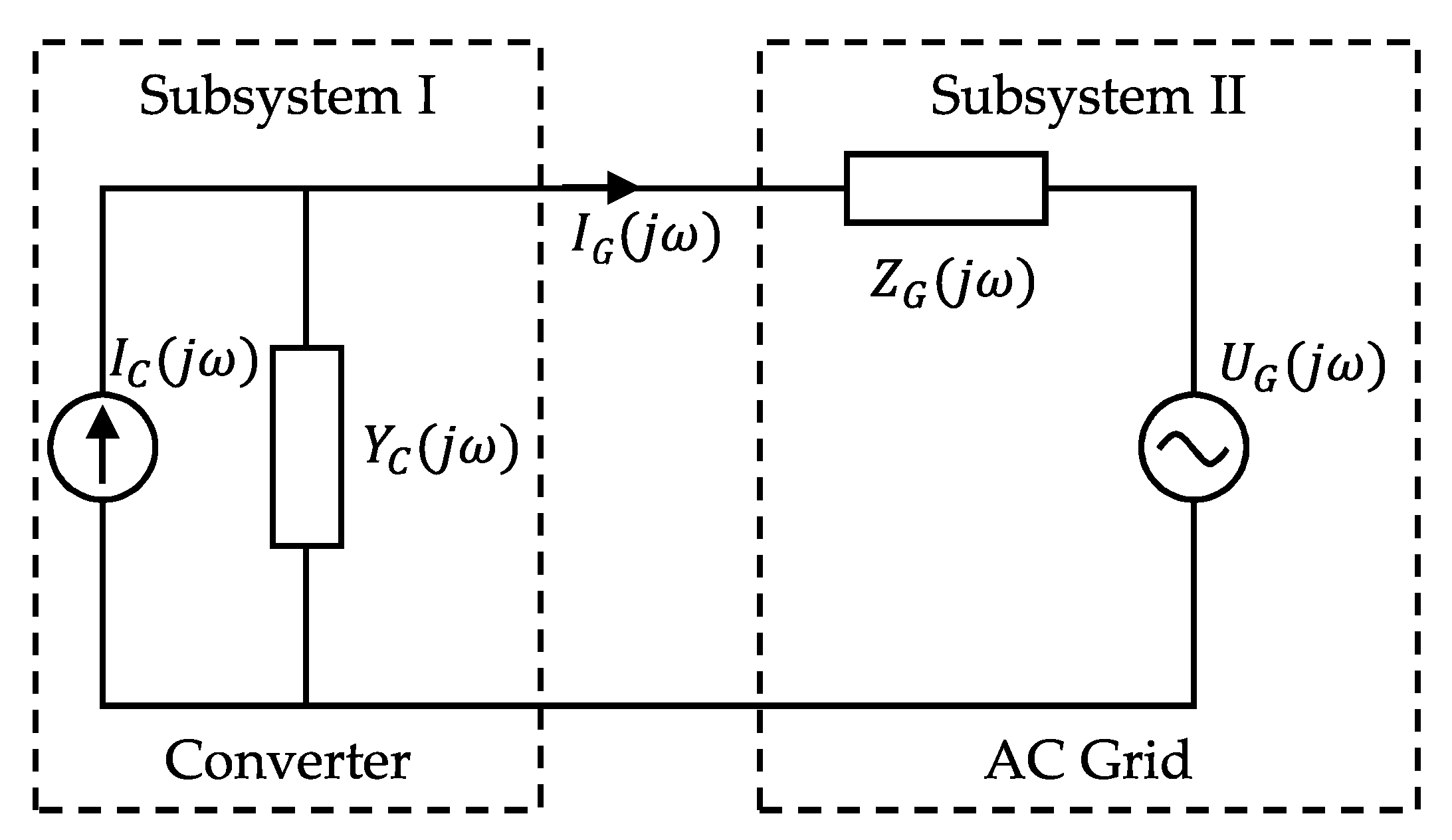
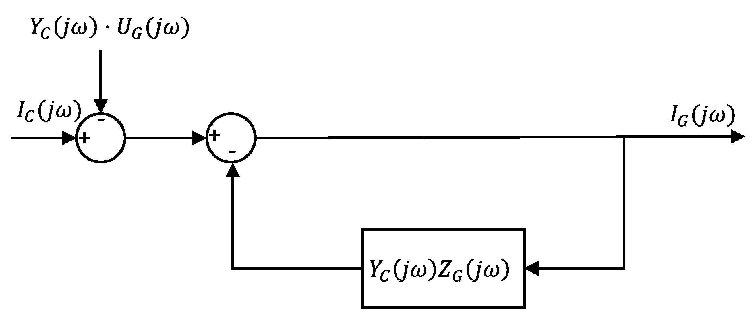
2. Impedance-Based Stability Assessment
2.1. Impedance-Based Stability Criterion
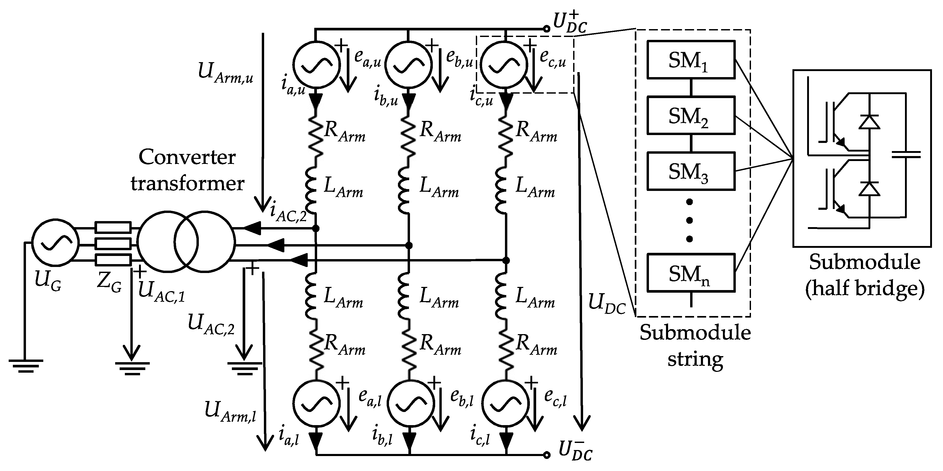
2.2. Impedance Model Derivation
2.3. Validation
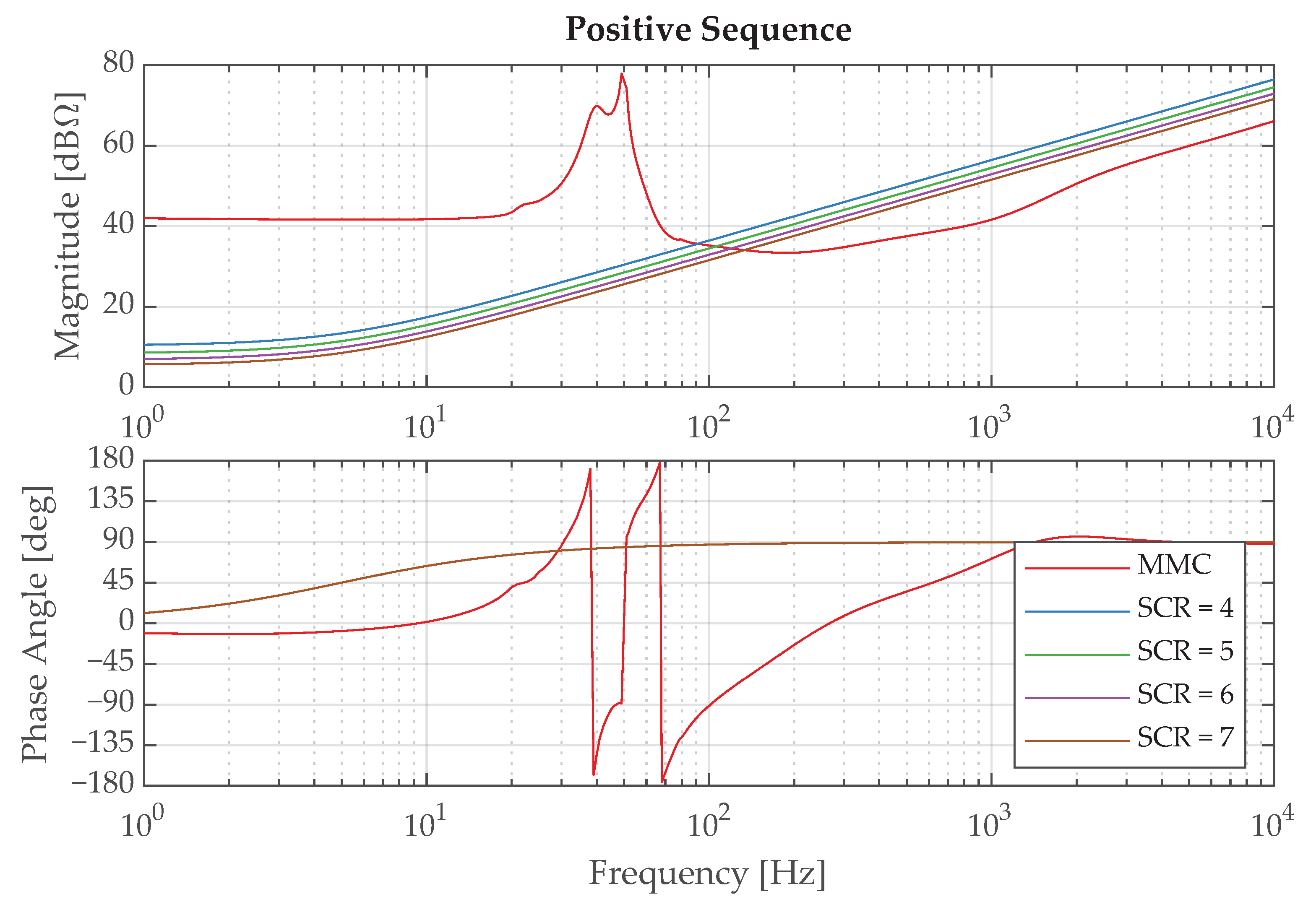
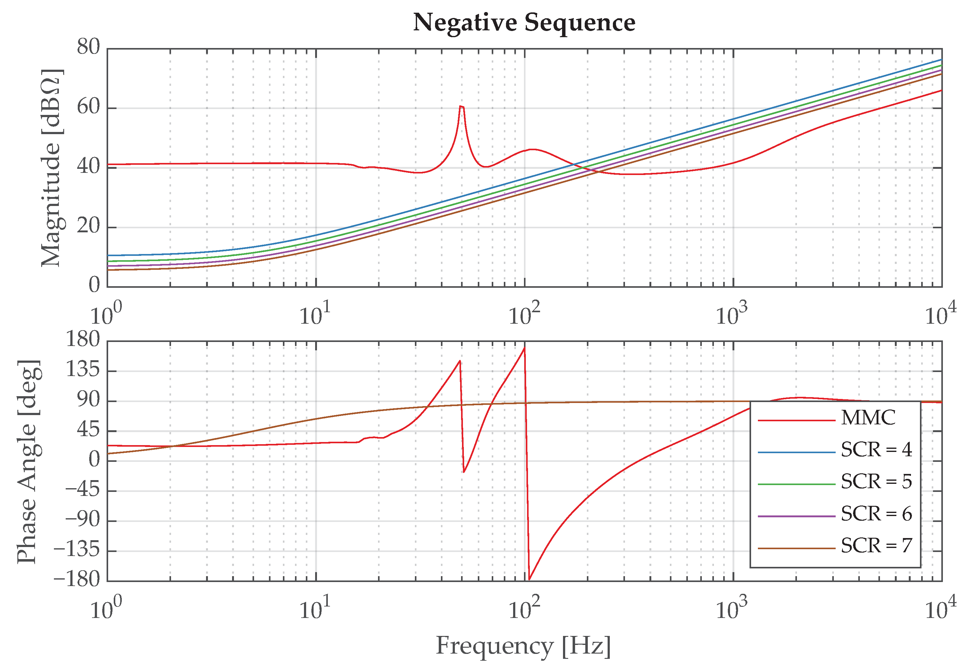
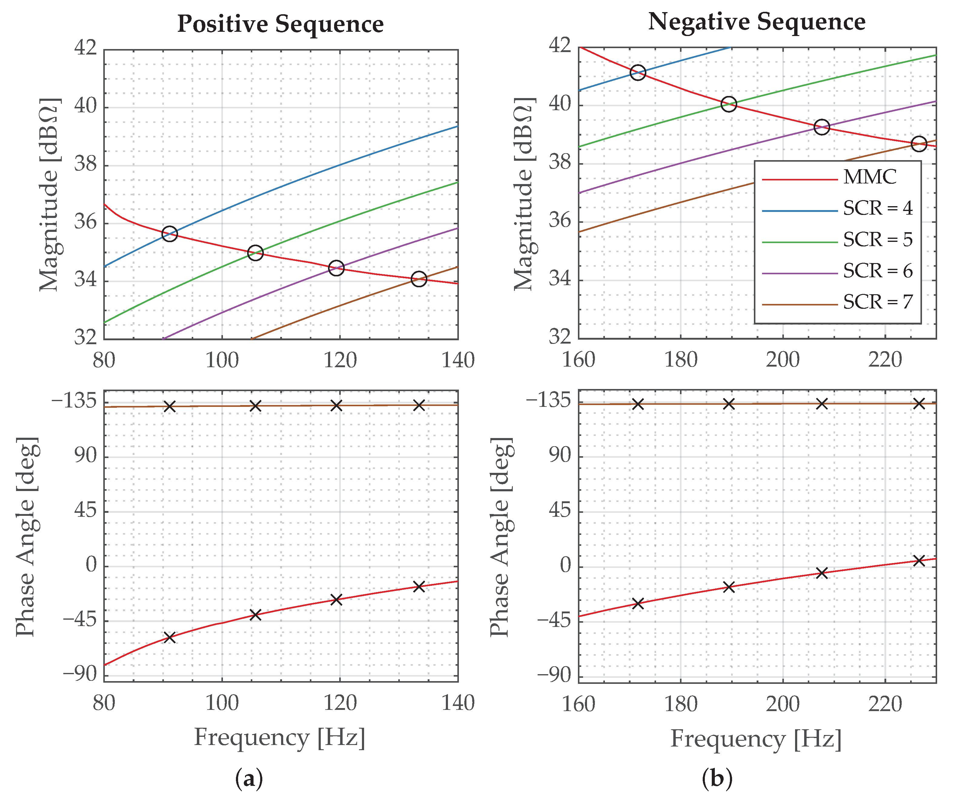
2.3.1. Frequency-Domain Stability Assessment
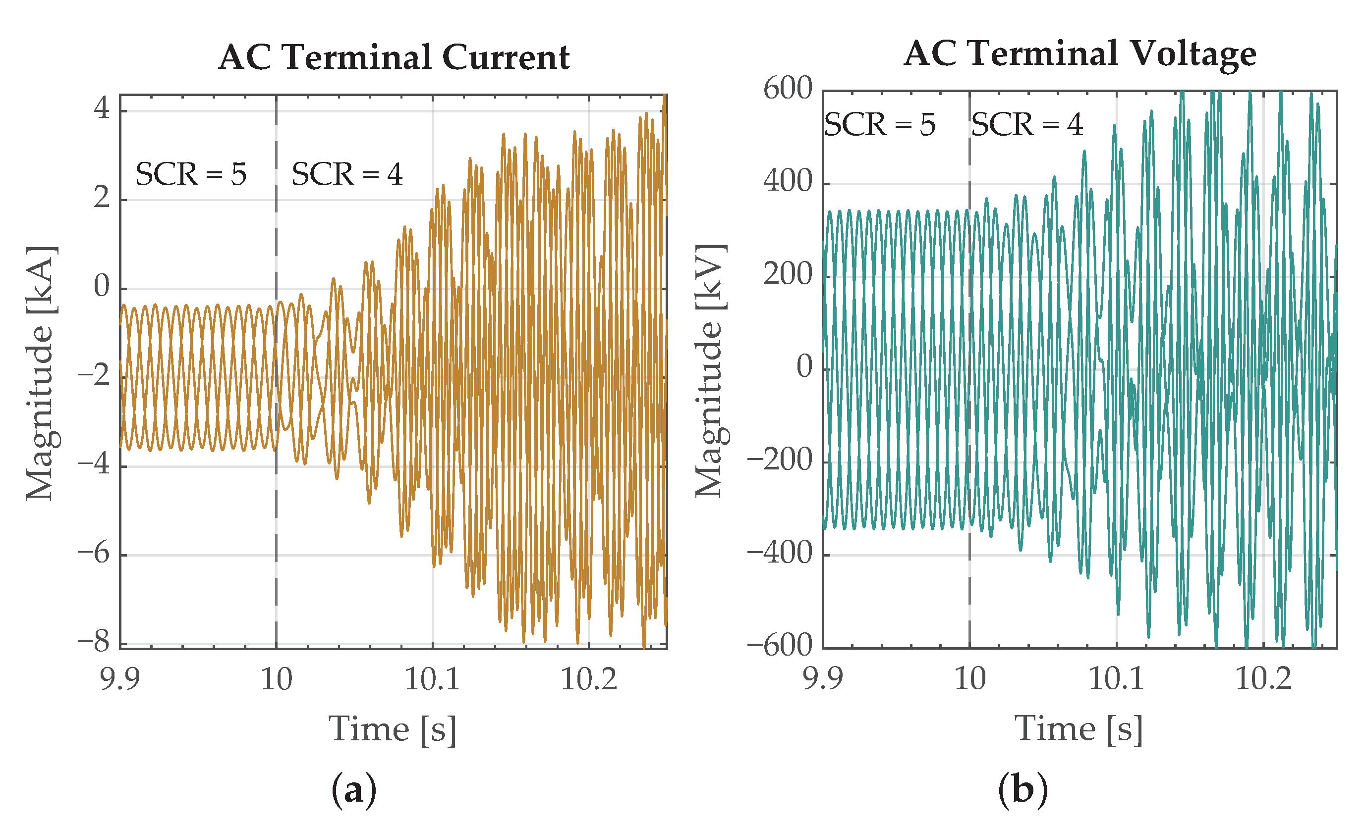
2.3.2. Time-Domain Validation
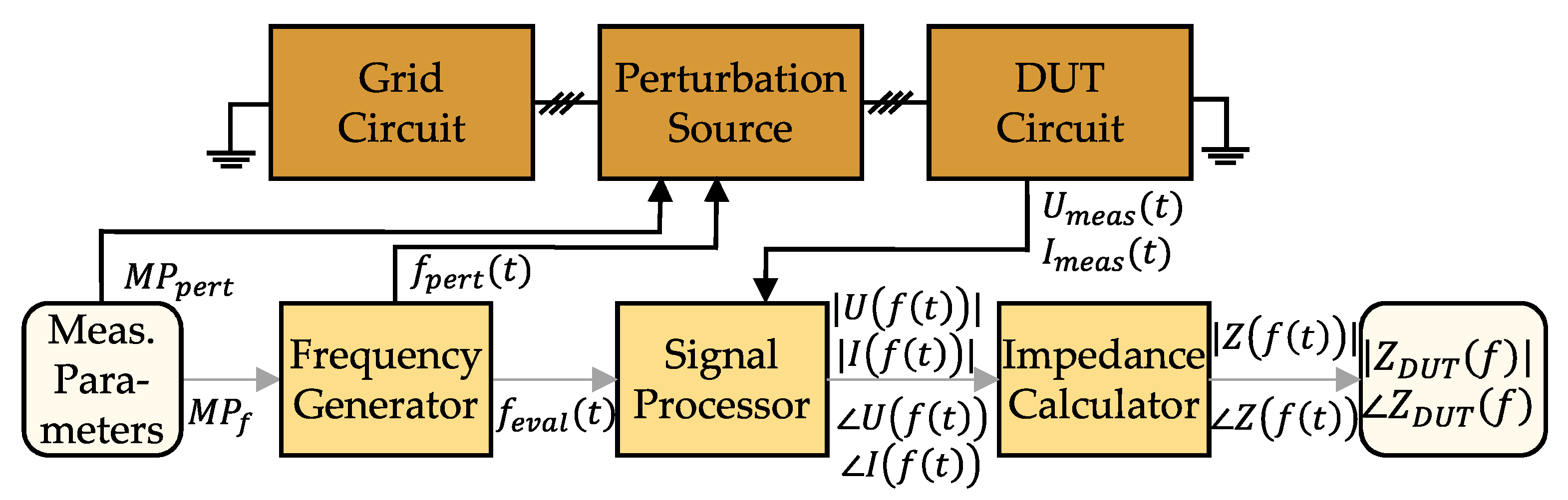
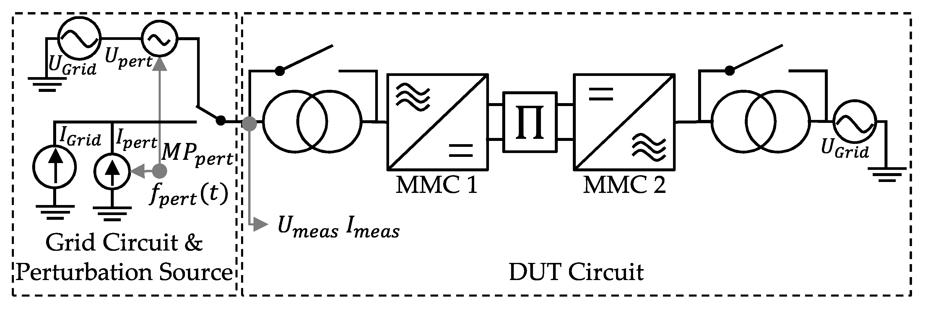
3. Extended MMC Impedance Derivation Method
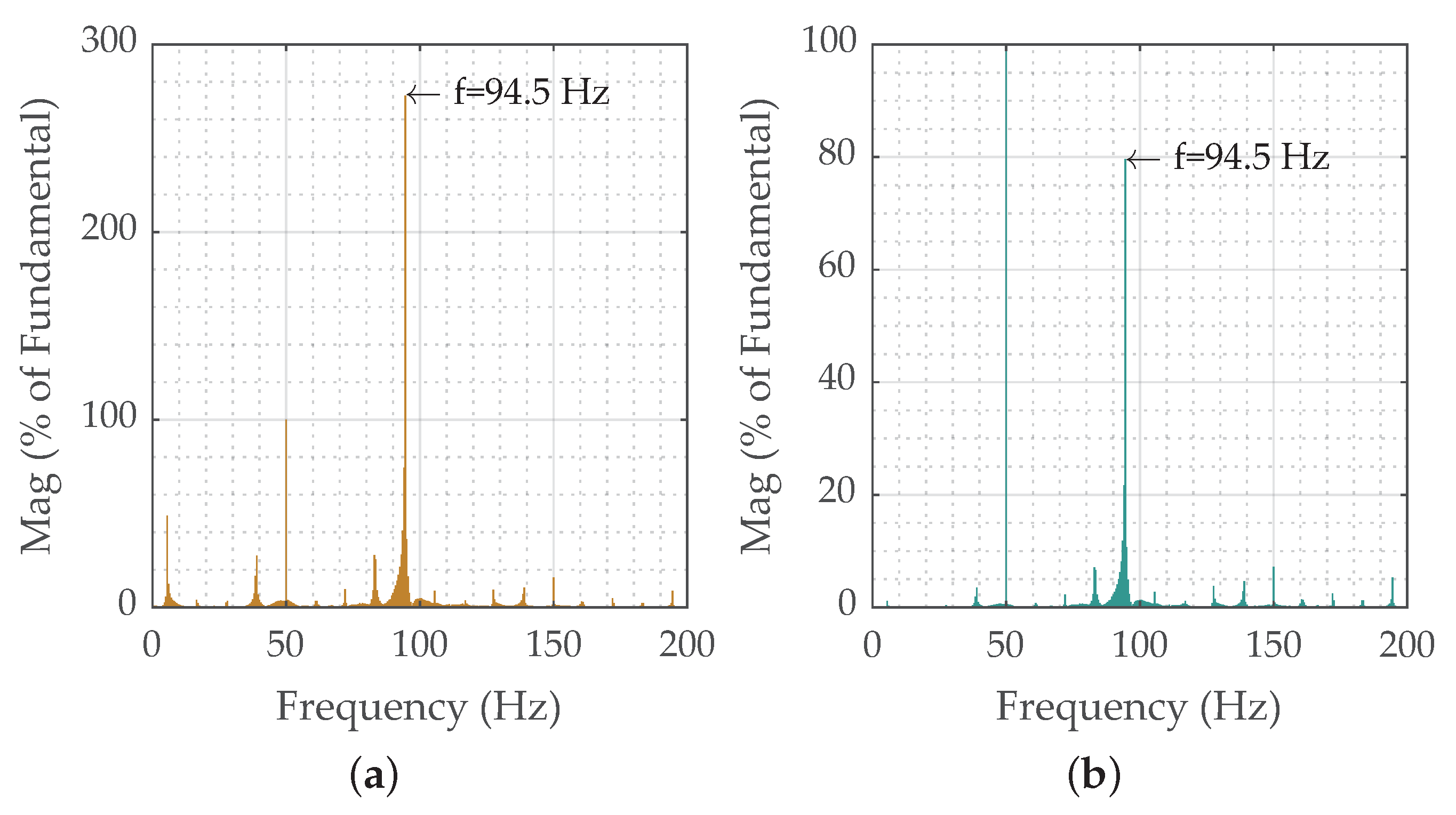
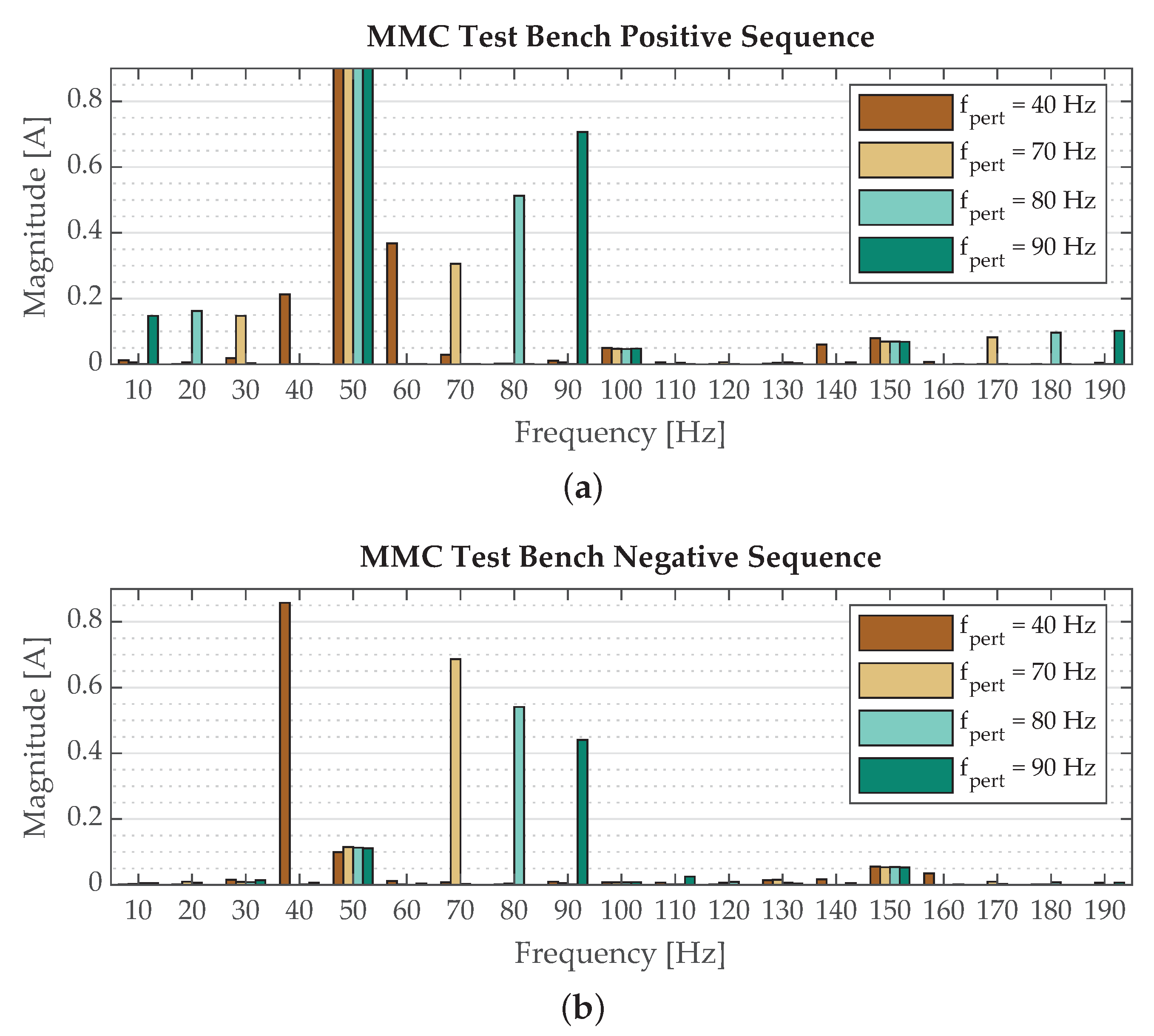
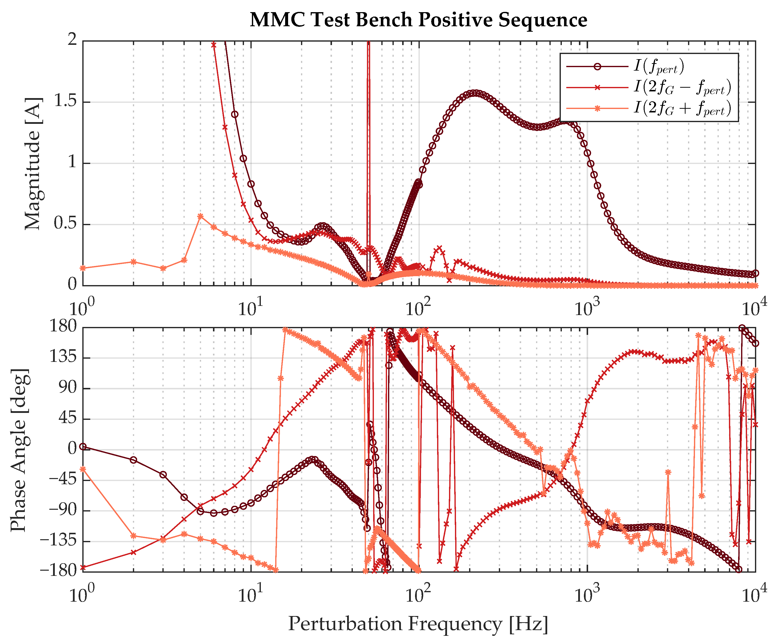
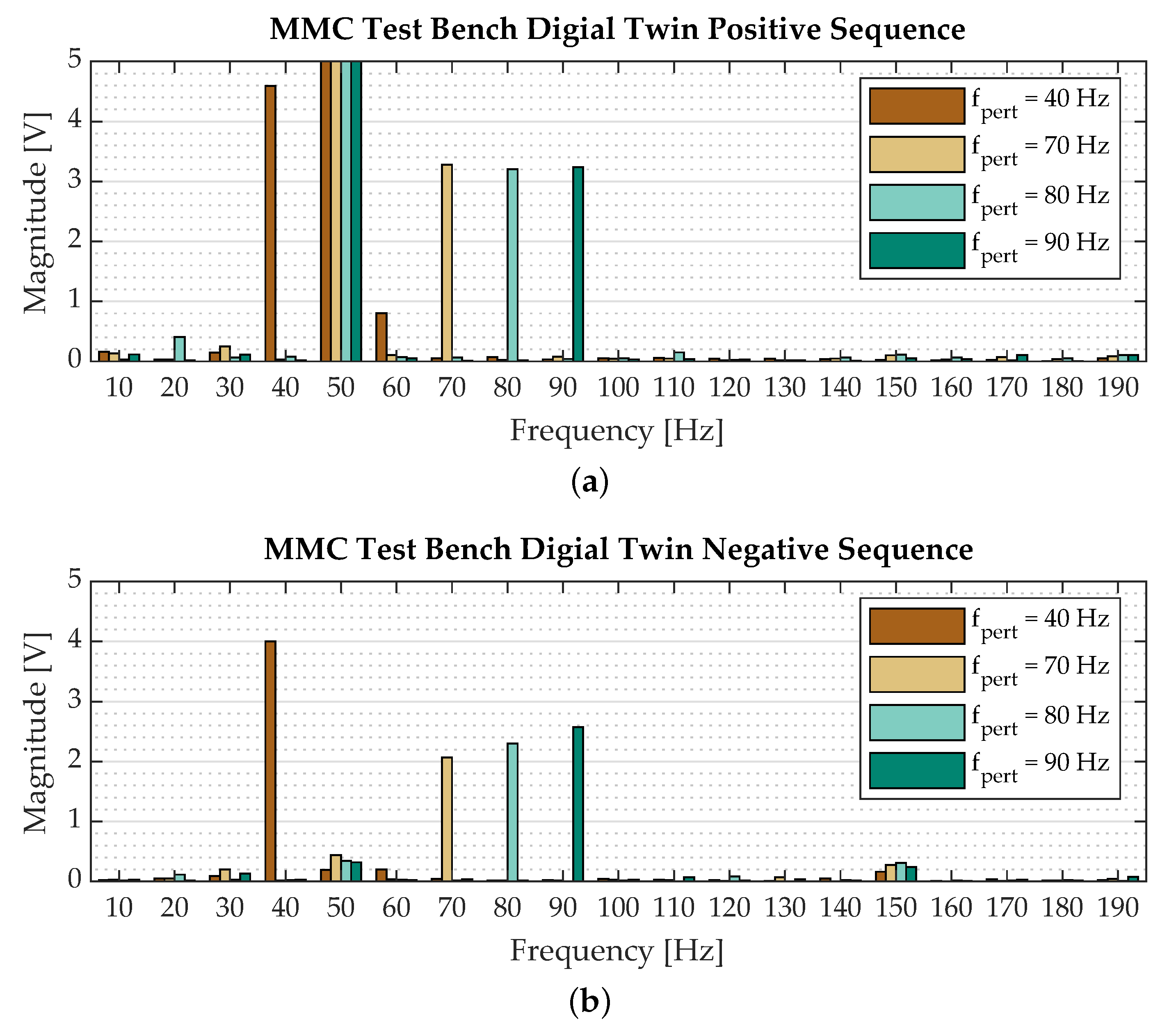
3.1. Spectrum Analysis
- the MMC operates in grid-following control mode,
- the MMC is subjected to a positive-sequence perturbation,
- the perturbation frequency is below 200 .
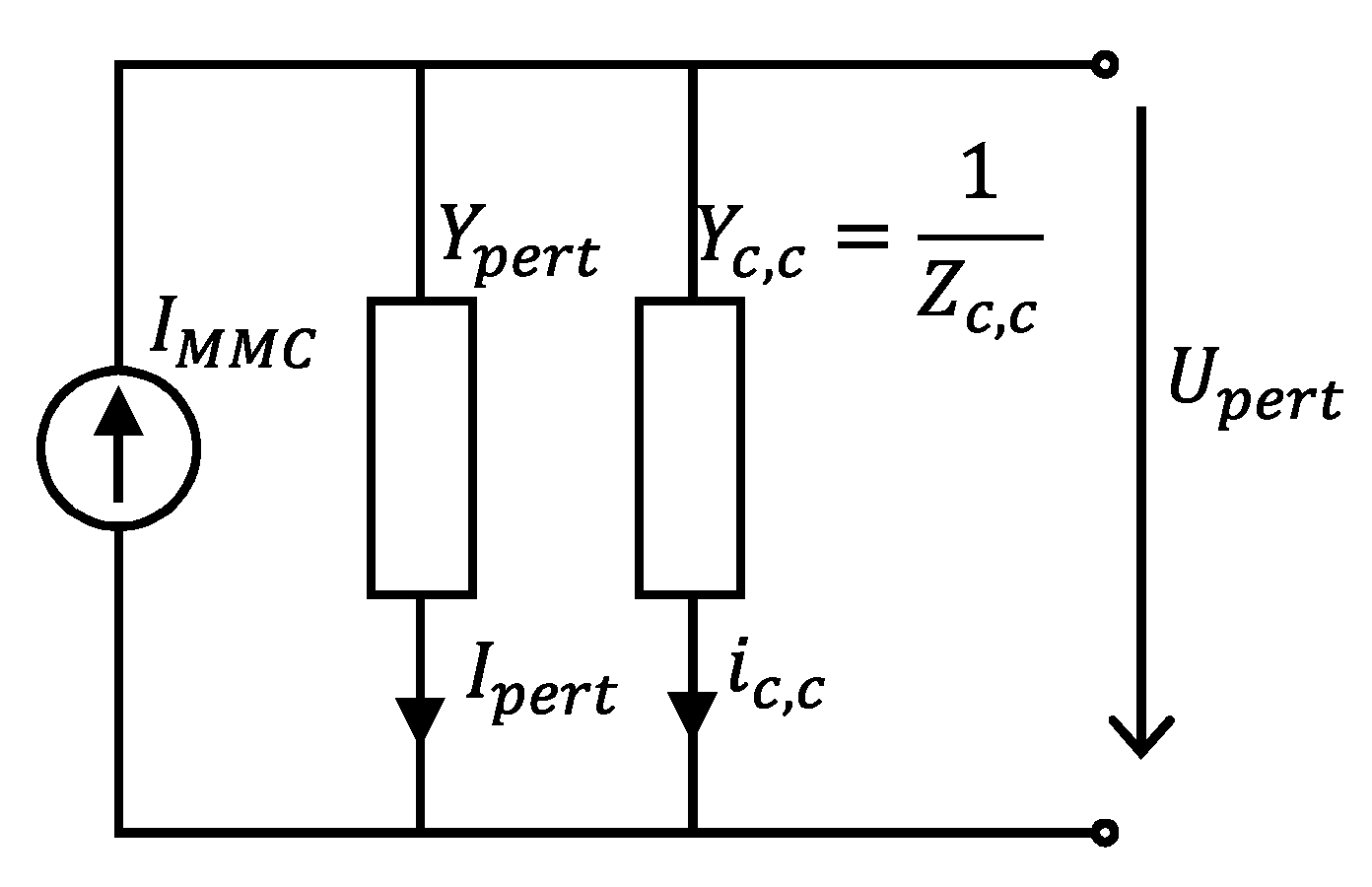
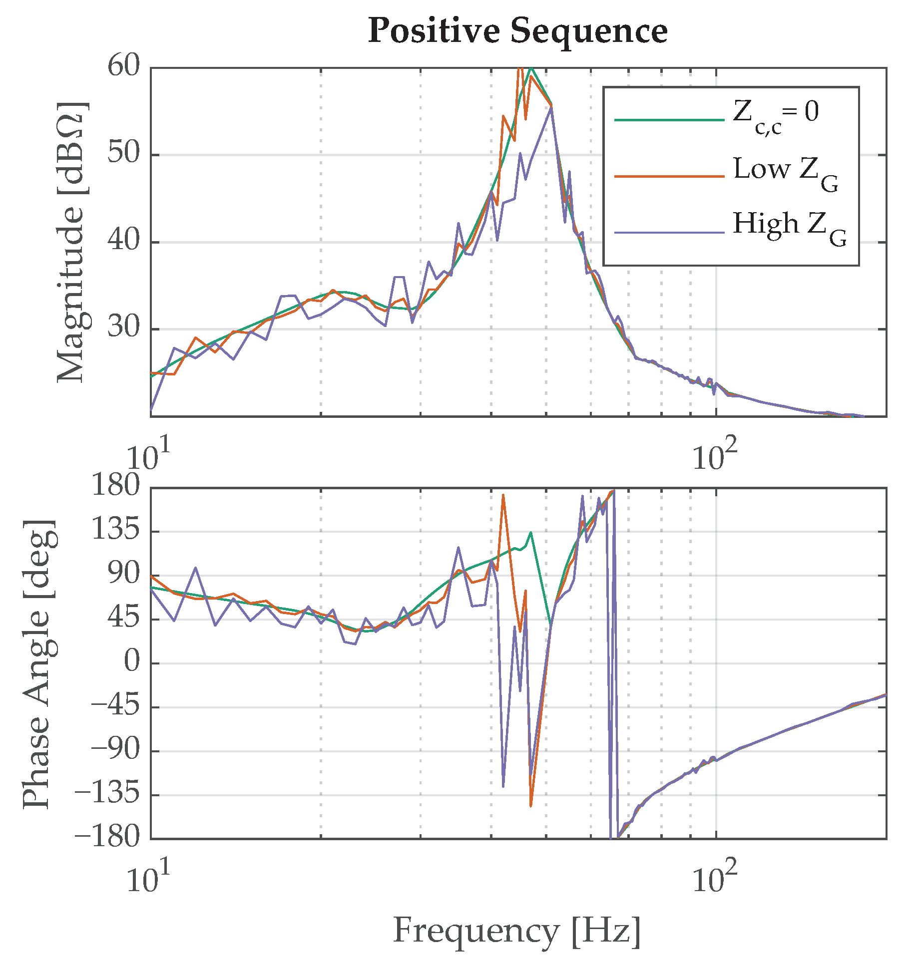
3.2. Coupling Modeling
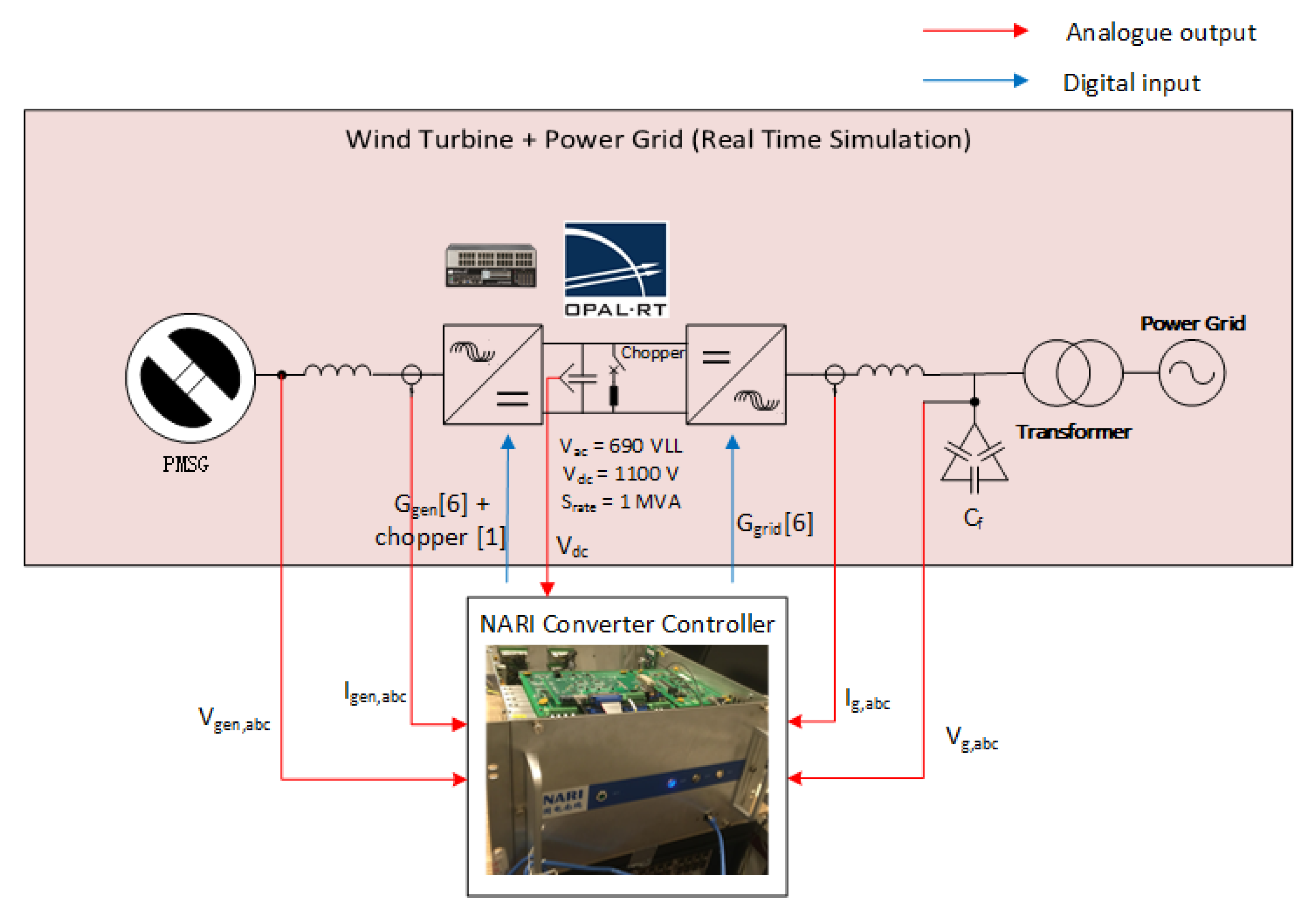
4. WT VSC Controller Replica System
- To propose a PHiL test circuit to derive the impedance model of the power converter unit of a vendor-specific wind turbine (i.e., the power converter unit of a commercial 1 wind turbine generator). Further details for the PHiL TB can be found in [40].
- To establish a CHiL TB to derive the impedance model a VSC WT controller replica that can be used for the grid integration of offshore wind power plants.
- To compare the PHiL impedance of the VSC with its equivalent CHiL and provide suggested practices for potential industrial applications.
- The OPAL-RT real-time simulator consisting of OP5700.
- A 1 WT VSC controller replica from Ming Yang Wind Power, Zhongshan, Guangdong, China.
5. Stability Analysis
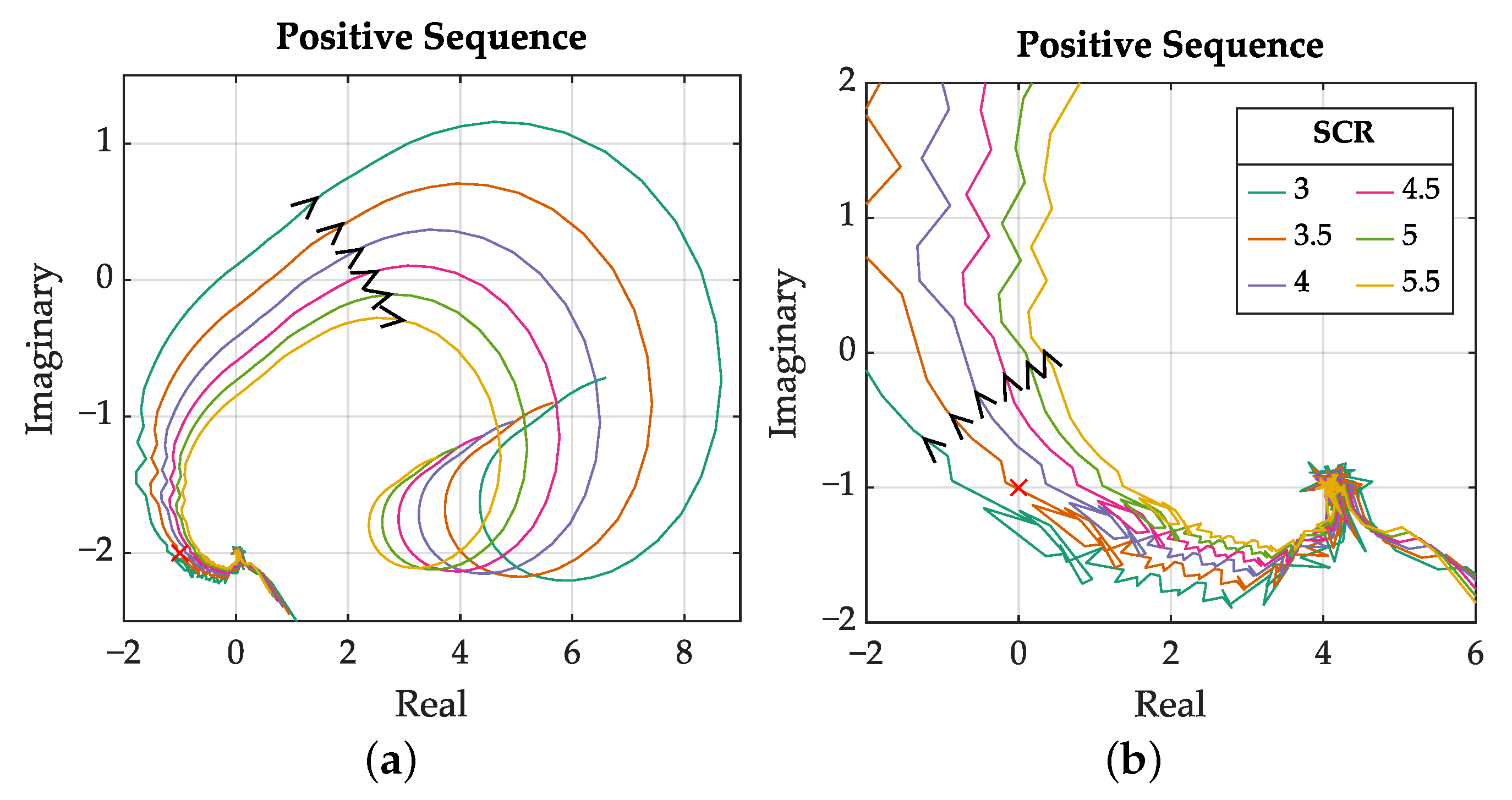
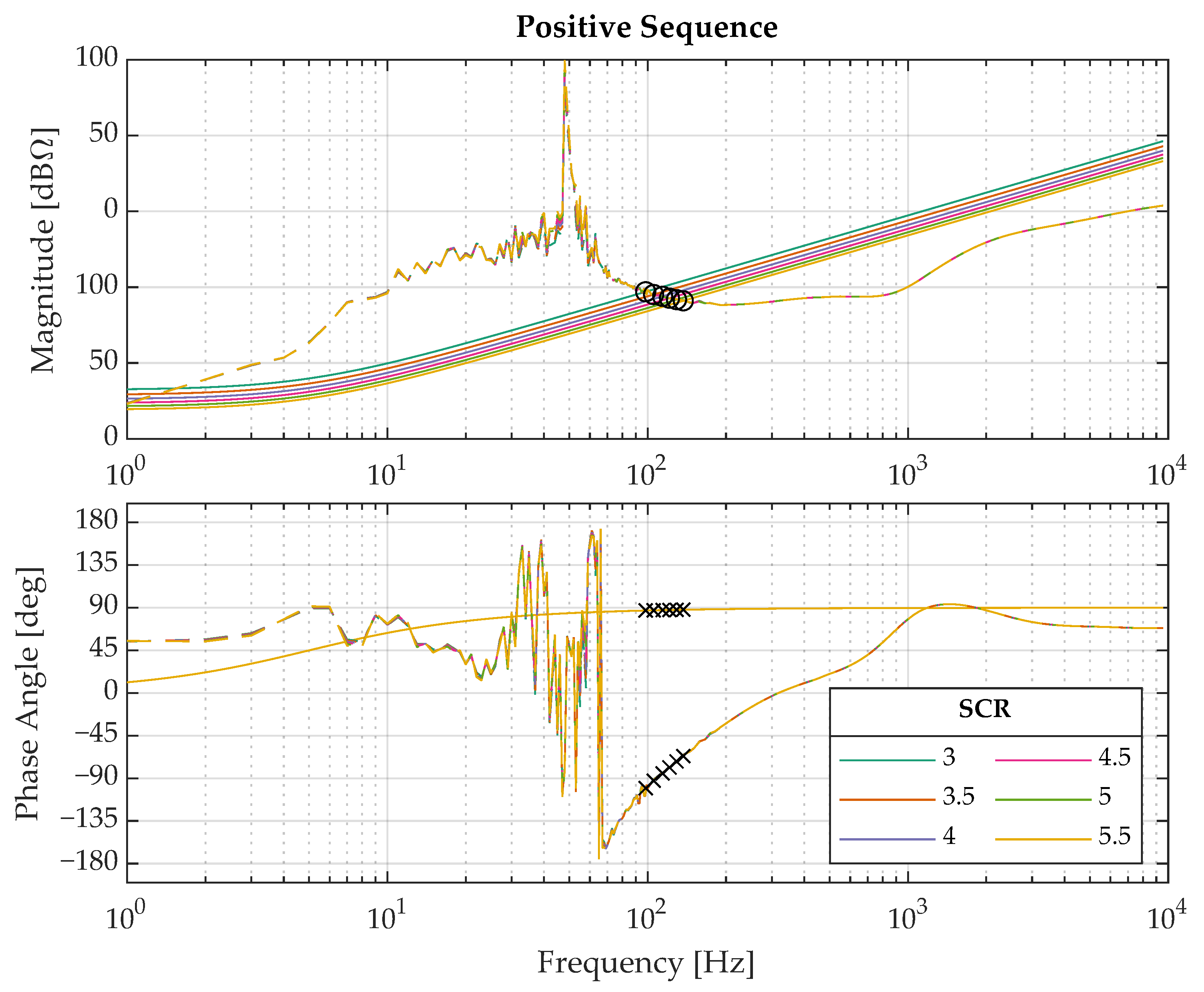
5.1. Onshore Test Case
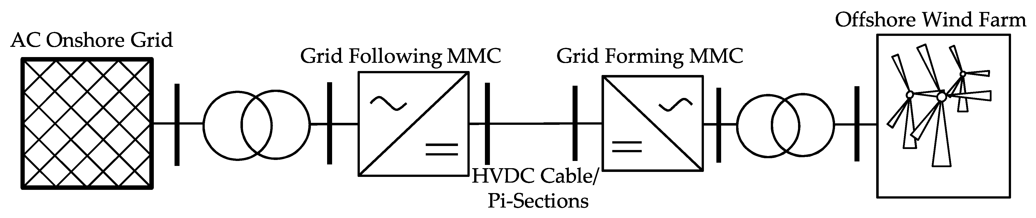
5.2. Offshore Test Case
6. Conclusions
Author Contributions
Funding
Conflicts of Interest
Abbreviations
| AC | Alternating Current |
| CHiL | Control Hardware in the Loop |
| DC | Direct Current |
| DUT | Device Under Test |
| EMT | Electromagnetic Transient |
| FPGA | Field Programmable Gate Array |
| HVDC | High-Voltage Direct Current |
| IbSC | Impedance-based Stability Criterion |
| MMC | Modular Multilevel Converter |
| MP | Measurement Parameters |
| NLM | Nearest-Level Modulation |
| PHiL | Power Hardware in the Loop |
| PLL | Phase-Locked Loop |
| PM | Phase Margin |
| PWM | Pulse-Width Modulation |
| SCR | Short-Circuit Ratio |
| SM | Submodule |
| STATCOM | Static Synchronous Compensator |
| TB | Test Bench |
| TSO | Transmission System Operator |
| VSC | Voltage Source Converter |
| WT | Wind Turbine |
Appendix A


References
- Jovcic, D. High Voltage Direct Current Transmission; Wiley: Hoboken, NJ, USA, 2019. [Google Scholar] [CrossRef]
- Thomas, T. Troubleshooting Continues. VDE VERLAG GMBH. 2014. Available online: https://www.offshorewindindustry.com/news/troubleshooting-continues (accessed on 16 April 2021).
- Saad, H. Performance Analysis of INELFE Link with Control Replicas. RTE, Techreport. 2016. Available online: https://docs.google.com/viewer?a=v&pid=sites&srcid=ZGVmYXVsdGRvbWFpbnxodmRjcmVwbGljYXdvcmtzaG9wfGd4OjcwNjI1ZjBjMjJiNDRmODM (accessed on 16 April 2021).
- Saad, H.; Fillion, Y.; Deschanvres, S.; Vernay, Y.; Dennetière, S. On resonances and harmonics in HVDC-MMC station connected to AC grid. IEEE Trans. Power Deliv. 2017, 32, 1565–1573. [Google Scholar] [CrossRef]
- Shu, D.; Xie, X.; Rao, H.; Gao, X.; Jiang, Q.; Huang, Y. Sub- and super-synchronous interactions between STATCOMs and weak AC/DC transmissions with series compensations. IEEE Trans. Power Electron. 2018, 33, 7424–7437. [Google Scholar] [CrossRef]
- Hatziargyriou, N.; Milanović, J.V.; Rahmann, C.; Ajjarapu, V.; Cañizares, C.; Erlich, I.; Hill, D.; Hiskens, I.; Kamwa, I.; Pal, B.; et al. Stability Definitions and Characterization of Dynamic Behavior in Systems with High Penetration of Power Electronic Interfaced Technologies; Techreport PES-TR77; IEEE Power & Energy Society: Piscataway, NJ, USA, 2020. [Google Scholar]
- Wang, X.; Blaabjerg, F. Harmonic stability in power electronic based power systems: Concept, modeling, and analysis. IEEE Trans. Smart Grid 2018, 10, 2858–2870. [Google Scholar] [CrossRef]
- Buchhagen, C.; Greve, M.; Menze, A.; Jung, J. Harmonic Stability—Practical Experience of a TSO. In Proceedings of the 15th Wind Integration Workshop, Vienna, Austria, 15–17 November 2016. [Google Scholar]
- Sun, J.; Vieto, I.; Larsen, E.V.; Buchhagen, C. Impedance-Based Characterization of Digital Control Delay and Its Effects on System Stability. In Proceedings of the 20th Workshop on Control and Modeling for Power Electronics (COMPEL), Toronto, ON, Canada, 17–19 June 2019; pp. 1–8. [Google Scholar] [CrossRef]
- Rault, P.; Despouys, O. D9.3: BEST PATHS DEMO#2: Final Recommendations for Interoperability of Multivendor HVDC Systems; Technical Report; Best Paths: Madrid, Spain, 2018. [Google Scholar]
- Amin, M. Small-Signal Stability Characterization of Interaction Phenomena between HVDC System and Wind Farms. Ph.D. Thesis, Norwegian University of Science and Technology, Trondheim, Norway, 2017. [Google Scholar]
- Middlebrook, R.D. Input Filter Considerations in Designand Application of Switching Regulators. In Proceedings of the IEEE Industry Applications Society Annual Meeting, Chicago, IL, USA, 11–14 October 1976; pp. 366–382. [Google Scholar]
- Sun, J. Impedance-based stability criterion for grid-connected inverters. IEEE Trans. Power Electron. 2011, 26, 3075. [Google Scholar] [CrossRef]
- Sun, J.; Li, M.; Zhang, Z.; Xu, T.; He, J.; Wang, H.; Li, G. Renewable energy transmission by HVDC across the continent: System challenges and opportunities. CSEE J. Power Energy Syst. 2017, 3, 353–364. [Google Scholar] [CrossRef]
- Cao, W. Impedance-Based Stability Analysis and Controller Design of Three-Phase Inverter-Based AC Systems. Ph.D. Thesis, University of Tennessee, Knoxville, TN, USA, 2017. [Google Scholar]
- Sun, J.; Liu, H. Sequence impedance modeling of modular multilevel converters. IEEE J. Emerg. Sel. Top. Power Electron. 2017, 5, 1427–1443. [Google Scholar] [CrossRef]
- Love, G.N. Small Signal Modelling of Power Electronic Converters, for the Study of Time-Domain Waveforms, Harmonic Domain Spectra, and Control Interactions. Ph.D. Thesis, University of Canterbury, Electrical and Computer Engineering, Christchurch, New Zealand, 2007. [Google Scholar]
- Love, G.N.; Wood, A.R. Harmonic State Space model of power electronics. In Proceedings of the 2008 13th International Conference on Harmonics and Quality of Power, Wollongong, NSW, Australia, 28 September–1 October 2008; pp. 1–6. [Google Scholar] [CrossRef]
- Familiant, Y.A.; Huang, J.; Corzine, K.A.; Belkhayat, M. New techniques for measuring impedance characteristics of three-phase AC power systems. IEEE Trans. Power Electron. 2009, 24, 1802–1810. [Google Scholar] [CrossRef]
- Huang, J.; Corzine, K.A.; Belkhayat, M. Small-signal impedance measurement of power-electronics-based AC power systems using line-to-line current injection. IEEE Trans. Power Electron. 2009, 24, 445–455. [Google Scholar] [CrossRef]
- Bessegato, L.; Harnefors, L.; Ilves, K.; Norrga, S. A method for the calculation of the AC-side admittance of a modular multilevel converter. IEEE Trans. Power Electron. 2019, 34, 4161–4172. [Google Scholar] [CrossRef]
- Wu, H.; Wang, X. Dynamic impact of zero-sequence circulating current on modular multilevel converters: Complex-valued AC impedance modeling and analysis. IEEE J. Emerg. Sel. Top. Power Electron. 2019, 8, 1947–1963. [Google Scholar] [CrossRef]
- Wang, X.; Harnefors, L.; Blaabjerg, F. Unified impedance model of grid-connected voltage-source converters. IEEE Trans. Power Electron. 2018, 33, 1775–1787. [Google Scholar] [CrossRef]
- Bessegato, L.; Ilves, K.; Harnefors, L.; Norrga, S. Effects of control on the AC-side admittance of a modular multilevel converter. IEEE Trans. Power Electron. 2019, 34, 7206–7220. [Google Scholar] [CrossRef]
- Bayo Salas, A. Control Interactions in Power Systems with Multiple VSC HVDC Converters. Ph.D. Thesis, KU Leuven, Leuven, Belgium, 2018. [Google Scholar]
- Zhang, Y.; Chen, X.; Sun, J. Sequence impedance modeling and analysis of MMC in single-star configuration. IEEE Trans. Power Electron. 2020, 35, 334–346. [Google Scholar] [CrossRef]
- Wang, X.; Blaabjerg, F.; Wu, W. Modeling and analysis of harmonic stability in an AC power-electronics-based power system. IEEE Trans. Power Electron. 2014, 29, 6421–6432. [Google Scholar] [CrossRef]
- Bakhshizadeh, M.K.; Wang, X.; Blaabjerg, F.; Hjerrild, J.; Kocewiak, Ł.; Bak, C.L.; Hesselbæk, B. Couplings in phase domain impedance modeling of grid-connected converters. IEEE Trans. Power Electron. 2016, 31, 6792–6796. [Google Scholar] [CrossRef]
- Dowlatabadi, M.B. Harmonic Modelling, Propagation and Mitigation for Large Wind Power Plants Connected via Extra Long HVAC Cables: With special focus on harmonic stability. Ph.D. Thesis, Aalborg Universitetsforlag, Aalborg, Denmark, 2018. [Google Scholar]
- Amin, M.; Molinas, M. Small-signal stability assessment of power electronics based power systems: A discussion of impedance- and eigenvalue-based methods. IEEE Trans. Ind. Appl. 2017, 53, 5014–5030. [Google Scholar] [CrossRef]
- Vieto, I.; Sun, J. On system modeling and analysis using DQ-frame impedance models. In Proceedings of the 2017 IEEE 18th Workshop on Control and Modeling for Power Electronics (COMPEL), Stanford, CA, USA, 9–12 July 2017. [Google Scholar] [CrossRef]
- Xiao, Q.; Mattavelli, P.; Khodamoradi, A.; Tang, F. Analysis of transforming dq impedances of different converters to a common reference frame in complex converter networks. CES Trans. Electr. Mach. Syst. 2019, 3, 342–350. [Google Scholar] [CrossRef]
- Quester, M.; Loku, F.; Yellisetti, V.; Puffer, R. Online Impedance Measurement of a Modular Multilevel Converter. In Proceedings of the 2019 IEEE PES Innovative Smart Grid Technologies Europe (ISGT-Europe), Bucharest, Romania, 29 September–2 October 2019; pp. 1–5. [Google Scholar] [CrossRef]
- Quester, M.; Loku, F.; Yellisetti, V.; Moser, A. Frequency Behavior of an MMC Test Bench System. In Proceedings of the 2020 6th IEEE International Energy Conference (ENERGYCon), Gammarth, Tunisia, 29 September–1 October 2020. [Google Scholar] [CrossRef]
- Middlebrook, R.D. Small-signal modeling of pulse-width modulated switched-mode power converters. Proc. IEEE 1988, 76, 343–354. [Google Scholar] [CrossRef]
- Liao, Y.; Wang, X. General Rules of Using Bode Plots for Impedance-Based Stability Analysis. In Proceedings of the 2018 IEEE 19th Workshop on Control and Modeling for Power Electronics (COMPEL), Padua, Italy, 25–28 June 2018. [Google Scholar] [CrossRef]
- Cespedes, M.; Sun, J. Impedance modeling and analysis of grid-connected voltage-source converters. IEEE Trans. Power Electron. 2014, 29, 1254–1261. [Google Scholar] [CrossRef]
- Liu, H. HVDC Converters Impedance Modeling and System Stability Analysis. Ph.D. Thesis, Rensselaer Polytechnic Institute, Troy, NY, USA, 2017. [Google Scholar]
- Sun, J.; Wang, G.; Du, X.; Wang, H. A theory for harmonics created by resonance in converter-grid systems. IEEE Trans. Power Electron. 2019, 34, 3025–3029. [Google Scholar] [CrossRef]
- Sun, Y.; Perez, A.N.F.; Yang, Y.; Burstein, A.W.; de Jong, E.C.W.; Tang, B. PROMOTioN Work Package 16 Harmonic Resonance Demonstrator: Wind Turbine Generator Input-Impedance Measurement in DQ Frame. In Proceedings of the 18th Wind Integration Workshop, Dublin, Ireland, 16–18 October 2019. [Google Scholar]
- Ruffing, P.; Loku, F.; Quester, M.; Yang, Y.; Harson, A.; Burstein, A.; Sun, Y.; Fabian, A. Deliverable 16.3: Overview of the Conducted Tests, the Results and the Associated Analyses with Respect to the Research Questions and Analyses within WP3; Technical Report, PROMOTioN Project; PROMOTioN—Progress on Meshed HVDC Offshore Transmission Networks: Arnhem, The Netherlands, 2020. [Google Scholar]
- Cigré Working Group B4.57. Guide for the Development of Models for HVDC Converters in a HVDC Grid; CIGRE: Paris, France, 2014. [Google Scholar]
- Ruffing, P.F. HVDC Grid Protection Based on Fault Blocking Converters. Ph.D. Thesis, RWTH Aachen University, Aachen, Germany, 2020. [Google Scholar] [CrossRef]
- Van Hertem, D. HVDC Grids: For Offshore and Supergrid of the Future; IEEE Press: Piscataway, NJ, USA; Wiley: Hoboken, NJ, USA, 2016. [Google Scholar]
- Loku, F.; Quester, M.; Wienkamp, P.; Kaiser, M.; Ruffing, P.; Bernal-Perez, S.; Martínez, J.; Blasco-Gimenez, R.; Arasteh, A.; Jahn, I.; et al. Deliverable 16.4—Test Case Analysis; Technical Report, PROMOTioN Project; PROMOTioN—Progress on Meshed HVDC Offshore Transmission Networks: Arnhem, The Netherlands, 2020. [Google Scholar]
- Rygg, A. Impedance-Based Methods for small-Signal Analysis of Systems Dominated by Power Electronics. Ph.D. Thesis, Norwegian University of Science and Technology, Trondheim, Norway, 2018. [Google Scholar]
- Vieto, I.; Huang, P.; Reinikka, T.; Nademi, H.; Buchhagen, C.; Sun, J. Online Measurement of Offshore Wind Farm Impedance for Adaptive Control of HVDC Transmission Systems. In Proceedings of the 2019 20th Workshop on Control and Modeling for Power Electronics (COMPEL), Toronto, ON, Canada, 17–20 June 2019; pp. 1–8. [Google Scholar] [CrossRef]
- Yang, D.; Wang, X.; Blaabjerg, F. Sideband harmonic instability of paralleled inverters with asynchronous carriers. IEEE Trans. Power Electron. 2018, 33, 4571–4577. [Google Scholar] [CrossRef]
- Vieto, I.; Sun, J. Sequence Impedance Modeling and Converter-Grid Resonance Analysis Considering DC Bus Dynamics and Mirrored Harmonics. In Proceedings of the 2018 IEEE 19th Workshop on Control and Modeling for Power Electronics (COMPEL), Padua, Italy, 25–28 June 2018; p. 8. [Google Scholar] [CrossRef]
- Sun, Y.; Ruffing, P.; Quester, M.; Bernal-Perez, S.; Añó-Villalba, S.; Yang, R.B.G.Y.; Dowlatabadi, M.K. Deliverable 16.5: Implementation of an Analytical Method for Analysis of Harmonic Resonance Phenomena; Technical Report, PROMOTioN Project; PROMOTioN—Progress on Meshed HVDC Offshore Transmission Networks: Arnhem, The Netherlands, 2019. [Google Scholar]
- Dowlatabadi, M.; Hjerrild, J.; Kocewiak, Ł.; Blaabjerg, F.; Bak, C. On Aggregation Requirements for Harmonic Stability Analysis in Wind Power Plants. In Proceedings of the 16th Wind Integration Workshop, Berlin, Germany, 25–27 October 2017. [Google Scholar]
- Quester, M.; Yellisetti, V.; Loku, F.; Puffer, R. Assessing the Impact of Offshore Wind Farm Grid Configuration on Harmonic Stability. In Proceedings of the 2019 IEEE Milan PowerTech, Milan, Italy, 23–27 June 2019. [Google Scholar] [CrossRef]


| Parameter | Variable | Value |
|---|---|---|
| Converter power | 1200 | |
| DC voltage | 640 | |
| Arm inductance | ||
| Resistance arm inductance | ||
| On resistance | ||
| Number of SMs | 350 | |
| SM capacity | ||
| AC primary voltage | 400 | |
| AC secondary voltage | 350 | |
| Transformer reactance | ||
| Transformer inductance | ||
| Transformer reactance | ||
| Transformer inductance |
| SCR | [GVA] | [] | [mH] |
|---|---|---|---|
| 4 | 4.8 | 3.3168 | 105.58 |
| 5 | 6.0 | 2.6534 | 84.46 |
| 6 | 7.2 | 2.2112 | 70.38 |
| 7 | 8.4 | 1.8953 | 60.33 |
| SCR | ||||
|---|---|---|---|---|
| 4 | 91 | 172 | 17 | |
| 5 | 106 | 8 | 189 | 30 |
| 6 | 119 | 20 | 208 | 41 |
| 7 | 133 | 31 | 227 | 51 |
| Parameter | Variable | Value |
|---|---|---|
| Nominal output power | 6 | |
| Nominal DC voltage | 400 | |
| Nominal DC current | 15 | |
| Nominal frequency | 50 | |
| Nominal AC primary voltage (3-phase) | 400 (Line-to-line RMS) | |
| Nominal AC secondary voltage (3-phase) | 208 (Line-to-line RMS) | |
| Nominal AC RMS current at | ||
| MOSFET switching frequency | 0–10 | |
| Number of cells (submodules) | 10 | |
| Nominal cell voltage | 40 | |
| Cell capacitor | ||
| Arm inductor | ||
| Transformer rated power | 8 | |
| Transformer vector group | (Ynd11) |
| SCR | [Hz] | [deg] | [Hz] | [deg] |
|---|---|---|---|---|
| 3 | 95 | −8 | 169 | 7 |
| 3.5 | 105 | 0 | 179 | 15 |
| 4 | 114 | 8 | 190 | 22 |
| 4.5 | 121 | 14 | 199 | 28 |
| 5 | 129 | 20 | 209 | 34 |
| 5.5 | 137 | 25 | 220 | 40 |
Publisher’s Note: MDPI stays neutral with regard to jurisdictional claims in published maps and institutional affiliations. |
© 2021 by the authors. Licensee MDPI, Basel, Switzerland. This article is an open access article distributed under the terms and conditions of the Creative Commons Attribution (CC BY) license (https://creativecommons.org/licenses/by/4.0/).
Share and Cite
Quester, M.; Loku, F.; El Azzati, O.; Noris, L.; Yang, Y.; Moser, A. Investigating the Converter-Driven Stability of an Offshore HVDC System. Energies 2021, 14, 2341. https://doi.org/10.3390/en14082341
Quester M, Loku F, El Azzati O, Noris L, Yang Y, Moser A. Investigating the Converter-Driven Stability of an Offshore HVDC System. Energies. 2021; 14(8):2341. https://doi.org/10.3390/en14082341
Chicago/Turabian StyleQuester, Matthias, Fisnik Loku, Otmane El Azzati, Leonel Noris, Yongtao Yang, and Albert Moser. 2021. "Investigating the Converter-Driven Stability of an Offshore HVDC System" Energies 14, no. 8: 2341. https://doi.org/10.3390/en14082341
APA StyleQuester, M., Loku, F., El Azzati, O., Noris, L., Yang, Y., & Moser, A. (2021). Investigating the Converter-Driven Stability of an Offshore HVDC System. Energies, 14(8), 2341. https://doi.org/10.3390/en14082341