Article

A Novel Adaptive Function—Dual Kalman Filtering Strategy for Online Battery Model Parameters and State of Charge Co-Estimation

1
School of Information Engineering, Southwest University of Science and Technology, Mianyang 621010, China
2
School of Pharmacy and Life Sciences, Robert Gordon University, Aberdeen AB10-7GJ, UK
*
Author to whom correspondence should be addressed.
Energies 2021, 14(8), 2268; https://doi.org/10.3390/en14082268
Submission received: 18 March 2021 / Revised: 8 April 2021 / Accepted: 13 April 2021 / Published: 17 April 2021
(This article belongs to the Section D2: Electrochem: Batteries, Fuel Cells, Capacitors)

Abstract

:
This paper aims to improve the stability and robustness of the state-of-charge estimation algorithm for lithium-ion batteries. A new internal resistance-polarization circuit model is constructed on the basis of the Thevenin equivalent circuit to characterize the difference in internal resistance between charge and discharge. The extended Kalman filter is improved through adding an adaptive noise tracking algorithm and the Kalman gain in the unscented Kalman filter algorithm is improved by introducing a dynamic equation. In addition, for benignization of outliers of the two above-mentioned algorithms, a new dual Kalman algorithm is proposed in this paper by adding a transfer function and through weighted mutation. The model and algorithm accuracy is verified through working condition experiments. The result shows that: the errors of the three algorithms are all maintained within 0.8% during the initial period and middle stages of the discharge; the maximum error of the improved extension of Kalman algorithm is over 1.5%, that of improved unscented Kalman increases to 5%, and the error of the new dual Kalman algorithm is still within 0.4% during the latter period of the discharge. This indicates that the accuracy and robustness of the new dual Kalman algorithm is better than those of traditional algorithm.

1. Introduction

1.1. Motivation and Challenges

In recent years, electric vehicles (EVs) powered by lithium-ion battery (LiB) have become an indispensable part of the development of new energy. For EVs, it is not only necessary to continue to look for battery materials with excellent performance, but also to have a battery management system (BMS) to prevent the spontaneous combustion, self-explosion, and other dangerous incidents involving lithium-ion batteries under certain extreme conditions [1]. An accurate lithium-ion battery model is the basis for improving state-of-charge (SOC) estimation accuracy [2]. Therefore, the construction of an accurate battery model is the key to the BMS. We combine the equivalent circuit model identification theory of the battery with the SOC estimation method to lay the foundation for the subsequent accurate estimation of the SOC [3]. A targeted composite equivalent circuit model of aviation LiB is proposed, and the parameter identification method based on this model is introduced [4]. Impedance spectroscopy is used to model the LiBs, and an equivalent model with high fidelity is proposed, which can better reflect the internal state of the battery [5]. The equivalent hydraulic model was studied and the state-of-health (SOH) of the LiB was estimated [6].

1.2. Literature Review

Apart from research on the above-mentioned battery models, experts also analyzed factors that affect lithium-ion battery models. By studying the influence of measuring the time scale on the internal resistance characterization method of the LiB, the accuracy of LiB parameter identification was improved [7]. A split battery model was proposed, and an adaptive algorithm was used to estimate the SOC of the lithium-ion battery, which improved accuracy of SOC estimation [8]. Literature [9] established a dynamic model of lithium-ion batteries for EVs by analyzing the electro-thermal aging characteristics of LiBs. Using fuzzy logic to control the balance of the LiB pack [10], to some extent, improved the accuracy of the EV BMS and the safety of the whole vehicle.
Besides, the balance of the LiB is also an important part of the BMS. An online dynamic equilibrium adjustment strategy for high-power LiB packs was proposed, and the method of SOC estimation under the modified strategy was presented [11]. By studying the dynamic battery balance of the LiB pack with average SOC, the charging and discharging capacity between the battery packs was improved [12]. Through research on the internal resistance prediction technology of LiBs, the efficiency of BMS has been improved [13]. The effects of SOC and battery arrangement in a lithium-ion battery array on thermal runaway propagation were investigated; effective strategies have been developed to mitigate the severity of cascade failures, but none of these strategies alone was sufficient to safely transport and store the battery pack [14]. The electrochemical model of LiB based on physics was simplified, a novel SOC estimation method under the simplified two-dimensional model was provided, and the estimation method was applied to the actual vehicle [15].
With the improvement of the accuracy of LiB models, more and more battery SOC estimation methods have emerged. The battery temperature compensation model is combined with the extended Kalman filter (EKF) algorithm to improve the accuracy of SOC estimation [16]. By studying the dual Kalman filter LiB SOC estimation and introducing an adaptive algorithm, the robustness and adaptability of the algorithm are greatly improved [17]. The SOC and SOH of the EV lithium-ion battery were estimated jointly, which improved the overall performance of the EV BMS [18]. Under EV operating conditions, an open circuit voltage (OCV) reconstruction method for EV lithium-ion battery SOC estimation was proposed, which improved the SOC estimation accuracy significantly [19]. On the basis of considering temperature factors, we explore the influence of temperature on the accuracy of SOC estimation, and improve the accuracy of LiB state-of-charge estimation [20]. Aiming at achieving high-precision LiB pack SOC estimation, the balance current factor is introduced to correct the current magnification and retrograde to improve the estimation accuracy [21]. Based on the complex working environment of aviation LiBs, with the goal of improving the safety of aviation BMS, it is important to realize a high-efficiency real-time SOC prediction and estimation method [22]. Aiming at the influence of temperature changes and current noise in the process of SOC estimation, particle filter (PF) is used to estimate the SOC of battery samples, which improves the estimation accuracy [23]. The thermal safety of the high-energy-density lithium-ion battery under different SOC has been studied, which promoted the improvement of energy density of the LiB [24].
With the deepening of SOC estimation algorithm research, new algorithms have been emerging endlessly [25,26]. Document [27] applies the recognition of the degradation state of LiBs to the BMS based on the analysis of the capacity increment of the fractional-order model, which improves the robustness of the system. Besides, a method for estimating the state-of-charge of LiBs based on reinforcement learning and an electrochemical model based on the double layer effect have been successively proposed and applied, providing a theoretical basis for the accurate estimation of SOC [28,29]. A new energy management optimization strategy is proposed, which is based on the identification of the maximum efficiency range, which effectively solves the hydrogen consumption problem of the fuel cell hybrid power system [30]. Through the thermal analysis of the lithium-ion battery, a method for estimating the state of charge of the electrode under different states of charge and aging is proposed [31]. In addition, the online parameter identification algorithm is used to perform high-precision identification of battery model parameters, and on this basis, a new SOC joint estimation algorithm is proposed to improve the accuracy of SOC estimation [32]. The above-mentioned studies have effectively promoted the development of the global energy-saving and new-energy vehicle technology and industry.

1.3. Contributions

Among the above SOC estimation algorithms, the EKF algorithm does not obtain the global optimal solution, and the filtering effect of the UKF algorithm is not ideal when the system input change rate is large. In addition, the estimation of battery SOC is affected by multiple coupling factors inside the battery. Therefore, it is particularly important to explore a new high-precision and high-robust SOC joint estimation algorithm.
Compared with the above research, this paper considers the influence of battery charge and discharge internal resistance on SOC estimation on the basis of previous research. Compared with the above research, this paper considers the influence of battery charge and discharge internal resistance on SOC estimation based on previous studies, and proposes a new internal resistance—polarization circuit model (IR-PCM) equivalent circuit model. In addition, the offline parameter identification method based on least squares estimation is improved given the disadvantages of long time consumption and big errors of the traditional parameter identification method, solving the “data saturation” problem of the recursive least square (RLS) algorithm time-varying system. EKF is improved by adding an adaptive noise tracking algorithm and the Kalman gain of the unscented Kalman filter (UKF) algorithm is improved by adding a dynamic Equation to improve SOC identification accuracy and BMS robustness. In addition, Forgetting Factor Recursive Least Square (FFRLS) and the above-mentioned two improved algorithms are combined to propose a new adaptive function—a dual Kalman filter (AF-DKF) algorithm in this paper, which uses alternate operation of an adaptive extended Kalman filter (AEKF) and function—as well as a unscented Kalman filter (F-UKF), which gives the system higher estimation accuracy. The model and algorithm accuracy is verified through Beijing bus dynamic stress test (BBDST) working condition experiments, which provides a theoretical basis for future BMS R&D.

1.4. Paper Organization
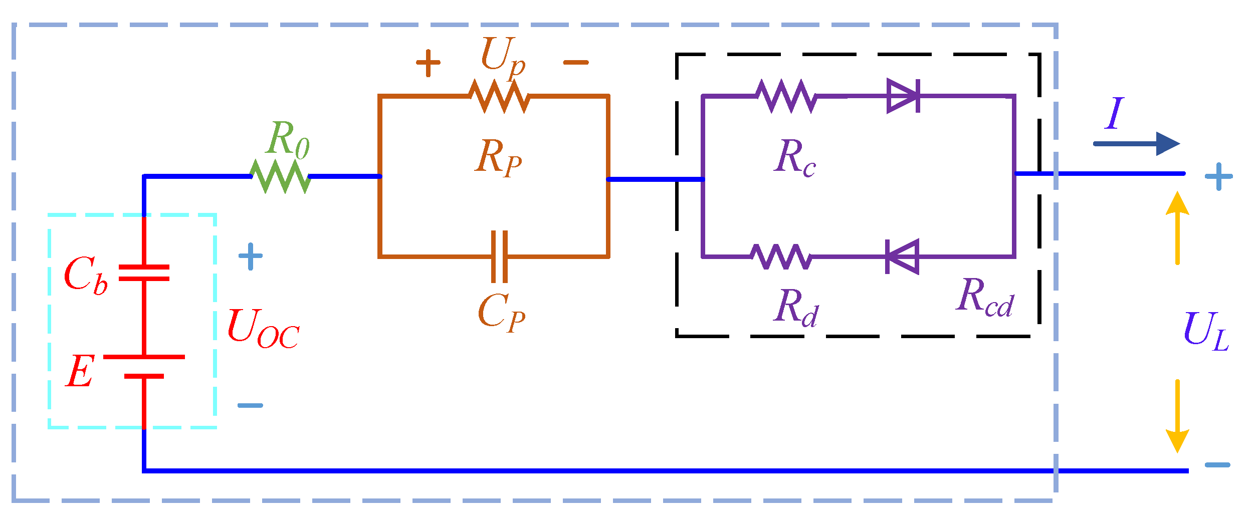
The structure of the remaining part of the paper is as follows. Section 2 is the LiB circuit modeling part, which mainly includes the construction of the lithium-ion battery IR-PCM equivalent circuit model and the online parameter identification based on FFRLS, as well as the AF-DKF algorithm to estimate the battery SOC principle. Section 3 is the LiB SOC estimation part, including the principle of estimating battery state of charge based on AEKF, F-UKF and AF-DKF algorithms. Section 4 is the experimental verification part, which mainly includes the fidelity verification analysis of the IR-PCM model and the robustness verification of the AF-DKF algorithm. Finally, the conclusion is shown in Section 5.

2. Circuit Modeling

2.1. Equivalent Model

An accurate LiB model can provide accurate data for battery management and SOC estimation and is the basis for improving SOC estimation accuracy. In order to better reflect the dynamic characteristics of the LiB in the charge and discharge state, the internal resistance difference of the LiB under the charge and discharge condition are considered. Based on the Thevenin equivalent circuit model, a new internal resistance—polarization circuit model (IR-PCM) of LiB charge and discharge is proposed. The IR-PCM structure is shown in Figure 1.
In the structure diagram of the IR-PCM, the internal resistance of LiB is represented by R0. The working current of LiB is represented by I. The terminal voltage value of LiB is represented by UL. Cb is the large capacitor, E is the voltage source, and Uoc is the open circuit voltage. Use Rp and Cp to characterize the polarization resistance and polarization capacitance of LiBs. The polarization characteristics inside the battery are characterized by a first-order resistor-capacitor circuit. Up is the polarization voltage. Rcd is used to represent the internal resistance Rc and Rd during charge and discharge. Improve and add a series of Rc and Rd parallel resistance circuits with reverse diodes to characterize the difference in charge-discharge internal resistance and further improve the accuracy of its working state description.

2.2. State Space Description

Based on IR-PCM in Figure 1 and Kirchhoff’s circuit law, the state space formula can be formed, as shown in Equation (1).
{ d U ( t ) / d t = I ( t ) / C P U ( t ) / C P R P U L ( t ) = U O C ( t ) U P ( t ) I ( t ) R 0 I ( t ) R c d
where t is the continuous time step, while UL(t) and UOC(t) are the closed-circuit voltage and open-circuit voltage of the battery at time t, respectively. I(t) is the current value at time t, Up(t) is the voltage at both ends of the polarization capacitor at time t.
The ideal battery source in IR-PCM is represented by OCV and the value is represented by Uoc. The OCV-SOC relationship is shown in Equation (2).
U O C ( t ) = f ( SOC )
For a complete BMS, it is necessary to consider the limit of SOC during operation. The real-time SOC value is calculated through the following Equation (3):
SOC ( t ) = SOC ( t 0 ) t 0 t ε 1 ε 2 I Q N d t
where SOC(t0) represents the initial value of SOC. ε1 represents the Coulomb efficiency at different I, which is assumed to be 1 for discharge and 0.98 for charge, ε2 represents the ambient temperature correction factor. QN is the rated capacity of the LiB sample.

2.3. Online Identification Based on FFRLS Algorithm

The RLS algorithm is widely used in system identification. For Single-Input Single-Output (SISO) systems, an Autoregressive Moving Average (ARMA) model can be used to describe the controlled objects, as shown in Equation (4).
y ( k ) = θ ( k ) φ ( k ) T + e ( k )
where k is the discrete time step. θ is the coefficient vector to be estimated, φ(k) is the data vector, and e(k) is system noise. According to Figure 1, the ARMA model can be described as shown in Equation (5).
{ φ ( k ) = [ y ( k 1 ) , x ( k ) , x ( k 1 ) ] θ ( k ) = [ a 1 ( k ) , b 1 ( k ) , b 2 ( k ) ] y ( k ) = a 1 y ( k 1 ) + b 1 x ( k ) + b 2 x ( k 1 ) ζ ( k ) = [ R 0 ( k ) , R P ( k ) , C P ( k ) , R c d ( k ) ]
where x(k) is the input vector of the system in the FFRLS algorithm, y(k) is the output variable of the system in the FFRLS algorithm, and ζ is the parameter to be identified in IR-PCM.
FFRLS adds an exponential forgetting factor to the RLS algorithm. By weighting the estimation error to optimize the objective function J(k), the problem of “data saturation” in the time-varying system of the RLS algorithm is solved [32]. The optimized objective function is Equation (6):
J ( k ) = k n λ n k e ( k ) 2
where λ is the forgetting factor, usually 0.9 < λ < 0.999, which is used to reduce the influence of the old number on the algorithm and reduce the current discrimination error.
Therefore, the FFRLS algorithm can be implemented using the following formula:
{ η ( k ) = [ P ( k 1 ) φ ( k ) ] / [ λ + φ ( k ) T P ( k 1 ) φ ( k ) ] θ ^ ( k ) = θ ^ ( k 1 ) + η ( k ) [ y ( k ) θ ^ ( k 1 ) φ ( k ) T ] P ( k ) = [ P ( k 1 ) η ( k ) φ ( k ) T P ( k 1 ) ] / λ
where θ ^ ( k 1 ) is the parameter estimation value at the previous moment, η(k) is the modified gain matrix, and P(k) represents the predicted covariance matrix.
In order to improve data utilization, this paper uses the FFRLS algorithm to perform online parameter identification of all parameters in IR-PCMZ. The proposed online parameter identification architecture is shown in Figure 2.
In Figure 2, using the FFRLS algorithm, the parameters in the model are solved online in a closed form, which mainly includes:
Step 1
According to the state equation of the model, the first order backward difference is used to obtain the discretized identification system seen in Equation (8).
U p ( k ) = R p C p R p C p + T U p ( k 1 ) + ( R 0 + R p R p C p + T ) I ( k ) R 0 R p C p R p C p + T I ( k 1 )
Step 2
Calculate U(k):
U ( k ) = U O C ( k ) U L ( k ) I ( k ) R 0 I ( k ) R c d
Step 3
Assume the form of the autoregressive Equation (10) for the system:
U ( k ) = a 1 U ( k 1 ) + b 1 I ( k ) + b 2 I ( k 1 )
Step 4
The coefficient matrix factorization is:
θ = [ a 1 , b 1 , b 2 ] = [ R p C p R p C p + T , R 0 + R p R p C p + T , R 0 R p C p R p C p + T ]
Step 5
The discrete parameter vector is:
ζ = [ R 0 , R P , C P , R c d ] = [ b 1 a 1 , a 1 b 1 b 2 a 1 ( a 1 + 1 ) , a 1 2 T a 1 b 1 b 2 , R n b 1 a 1 ]
where Rn is the direct measurement of the mixed resistance value after being completely shelved.

3. SOC Estimation

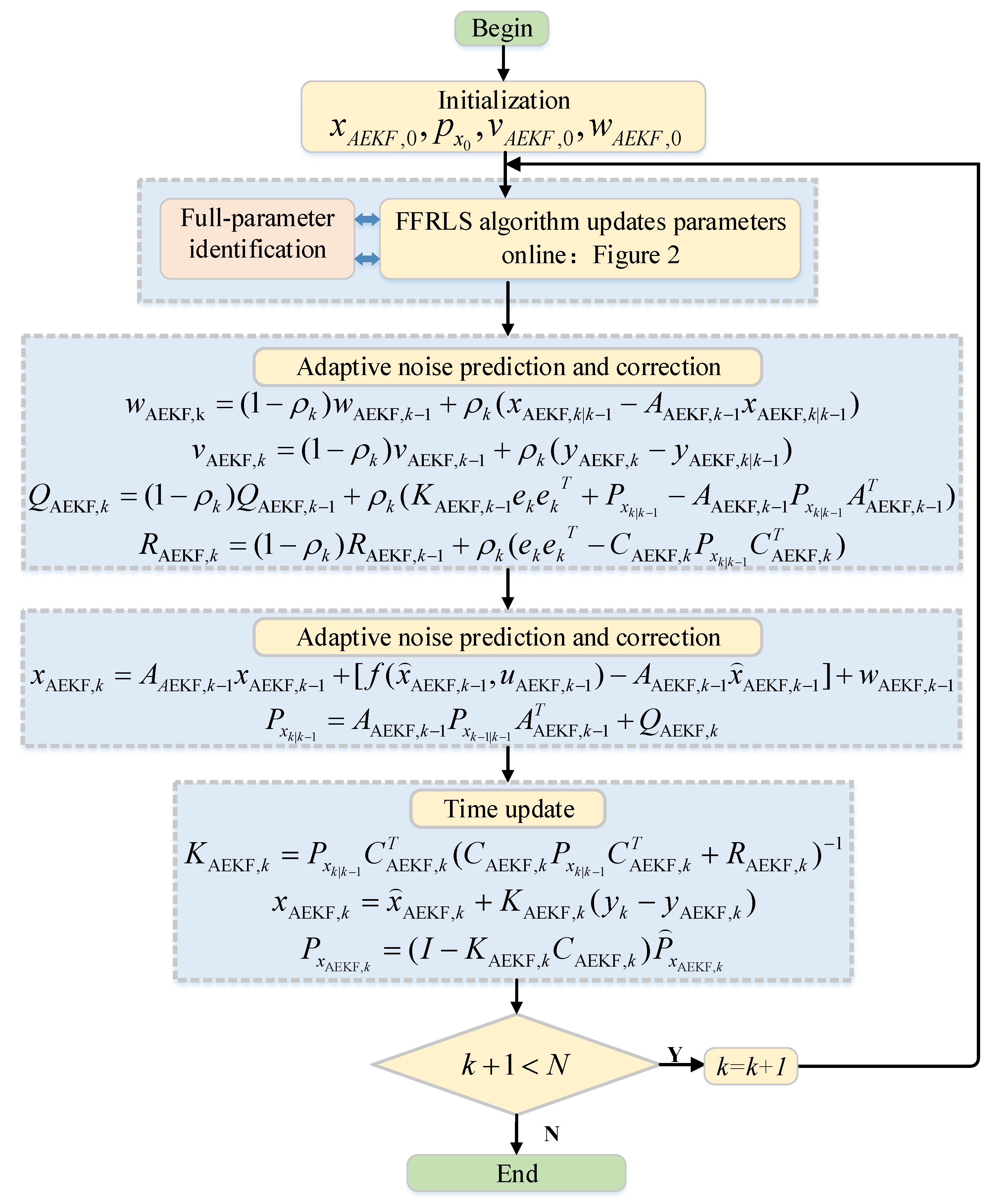
3.1. SOC Estimation Based on AEKF

When the EKF algorithm is used to estimate SOC of the LiB, the influence of noise cannot be ignored. An AEKF algorithm is proposed by combining the adaptive noise tracking algorithm and the EKF algorithm to eliminate the effect of noise on system robustness. SOC estimation of LiB is realized. For practical applicability of the AEKF algorithm, Equation (1) needs to be discretized, and the resulting formula is Equation (13).
{ x k = f ( x k 1 , u k 1 ) + w k y k = g ( x k , u k ) + v k
where xk = [SOC,Up]T is the state variable of AEKF algorithm iteration in the system, yk = UL is the output quantity of AEKF algorithm iteration in the system, uk = I is the input variable of the system, f(*) and g(*) are the nonlinear functions of the system, and wk and vk are the system noise.
Taylor expansion is carried out on the above-mentioned model at the moment of (xAEKF,k−1, uAEKF,k−1), only one term is retained, and Equation (14) can be obtained.
{ x k = f ( x k 1 , u k 1 ) + f x k 1 [ x k 1 x k 1 ] + w k 1 y k = g ( x k , u k ) + g x k [ x k x k ] + v k
Substitute the Equation (13) with Equation (14) to obtain the linearized system state output as Equation (15).
{ x k = A k 1 x k 1 + [ f ( x k 1 , u k 1 ) A k 1 x k 1 ] + w k 1 y k = C k x k + [ g ( x k , u k ) C k x k ] + v k
where x k 1 is the input signal of the system. Ak and Ck are the system matrix and the observation matrix, respectively, whose matrix expression is shown in Equation (16).
A k = [ 1 0 0 exp ( Δ t / C p R p ) ] , C k = [ d U O C ( SOC ) d SOC 1 ]
Based on FFRLS, online parameter identification can be carried out for key parameters of the LiB; the overall process of using AEKF algorithm to estimate SOC is shown in Figure 3.
The actual noise statistics cannot be obtained directly in practical application. In Figure 3, The adaptive algorithm noise matching algorithm is combined with the EKF algorithm to realize the adaptive matching of noise. The principle of estimation is as follows:
(1)
Update system noise and its covariance:
{ w k = ( 1 ρ k ) w k 1 + ρ k ( x k | k 1 A k 1 x k | k 1 ) Q k = ( 1 ρ k ) Q k 1 + ρ k ( K AEKF , k 1 e k e k T + P x k | k 1 A k 1 P x k | k 1 A k 1 T )
(2)
Update observation noise and its covariance:
{ v k = ( 1 ρ k ) v k 1 + ρ k ( y k y k | k 1 ) R k = ( 1 ρ k ) R k 1 + ρ k ( e k e k T C k P x k | k 1 C k T )
(3)
Conduct an iterative calculation of ek and ρk:
{ e k = y k y k | k 1 v k 1 ρ k = ( 1 σ ) / ( 1 σ k 1 )
where σ is the forgetting factor of AEKF, and its value is σ ( 0.95 , 0.99 ) .
Based on the analysis, although the EKF algorithm combined with the adaptive noise matching algorithm cannot completely eliminate wk and vk, the AEKF algorithm can update the noise at each moment in the iterative process, which greatly improves the stability and performance robustness of the system, thereby improving the battery SOC’s estimation accuracy.

3.2. SOC Estimation Based on F-UKF

When using the AEKF algorithm to estimate lithium-ion SOC, we found that the SOC estimation error is increasing over time under the constant current discharge condition. Besides, it is required at this stage to find the derivative for the non-linear function in the AEKF algorithm recurrent formula and calculate the Jacobian matrix, which greatly increases the BMS processor’s burden. There are also some problems when the UKF algorithm is used for lithium-ion battery SOC estimation. When UKF is in an unstable operating environment, the tracking performance of the algorithm is affected by two conflicting factors: the state fluctuation caused by convergence speed and the algorithm noise. For example, if the BMS input current undergoes step changes, the performance of UKF is not ideal. To overcome this weakness, the Kalman gain is improved based on traditional UKF and F-UKF with dynamic function improvement. Since the F-UKF algorithm and the UKF algorithm are only different in the Kalman gain correction method, this paper only provides the part of improving the Kalman gain in the UKF. The iterative process of the improved algorithm is shown in Figure 4 below.
According to Figure 4, the improvement method is as follows:
The modification of the dynamic function needs to meet certain threshold conditions. According to the analysis of experimental conditions, it can be known that when the input change of the BMS satisfies the condition shown in Equation (20), the modification of the dynamic function is triggered
I k I k 1 Δ t I max
where ΔImax is the set value for the maximum current change. The adaptive modification of the dynamic function uses the limit idea. According to the system current change rate, the Kalman gain can be adjusted adaptively to complete the accurate SOC estimation. The form of the dynamic function and the modified Kalman gain are shown in Equation (21).
{ K F UKF , k = γ   K F UKF , k = γ   ( P x y , k P x y , k 1 ) x k = x k + K F UKF , k ( y k y k | k 1 )
where γ represents the weighting factor of the dynamic function. Based on the previous algorithm test result, γ is set to γ ( 1 , 1.2 ) . The greater its value, the more obviously the Kalman coefficient will be corrected. However, its value shall not be too great to avoid system overshooting.
A dynamic function is introduced to strengthen the correction for the Kalman gain to ensure system stability and ideal correction for the Kalman gain through the weight factor, as well as preventing system overshooting. The Kalman function value is dynamically adjusted based on the system’s operating current changes. The dynamic function is shown in Equation (22).
{ K F UKF , k = γ   K F UKF , k K F UKF , k = ϕ   K F UKF , k ϕ = ( 1 + α 1 I k I k 1 )
where ϕ is a dynamic function, α is a value to be specified in the function, and α ( 0 , 1 ) . According to the nature of the exponential function, the value range of the dynamic function value is ϕ ( 1 , 2 ) . The function indicates that within two consecutive step sizes, the greater the current difference, the greater the ϕ value and the faster the convergence of the Kalman coefficient. The Kalman gain is dynamically adjusted based on the weight factor by recording the current values of two step size moments. As a result, the state variable is indirectly dynamically adjusted and the system robustness is enhanced. The state estimation measurement is updated by using the above-mentioned improvement strategy. The updated state variable is shown in Equation (23).
x k = x k + K F UKF , k ( y k y k | k 1 )

3.3. Joint Estimation Algorithm

Based on the above-mentioned research, SOC estimation through AF-DKF combining AEKF and F-UKF based on the FFRLS online parameter identification algorithm still have high accuracy and anti-interference capability, while good BMS robustness is ensured. This joint algorithm combines the AEKF, F-UKF and FFRLS algorithms to achieve real-time update of model parameters and online SOC estimation. The flowchart is shown in Figure 5.
As shown in Figure 5, two SOC calculation modules are for simultaneous real-time SOC estimation, with one using the AEKF algorithm. The other one first uses the AEKF algorithm, a transfer function is then added, and an improved UKF algorithm through a dynamic function is used for SOC estimation. Weighted mutation is implemented for the estimation results of the two modules to obtain the estimation values of the current battery SOC. The implementation steps of the AF-DKF algorithm are as follows:
(1)
Conduct a static discharge experiment for the battery to obtain the expression showing the relationship between the OCV and the SOC.
(2)
Use the AEKF algorithm to estimate the SOCAEKF,k of the current battery based on the IR-PCM and state space formula created in Figure 1.
(3)
Judge whether the iterative step size is greater than the set value T. If it is, proceed to the next step.
(4)
Add a transfer function to conduct benign interference with the SOC value obtained through the AEKF algorithm. A new SOC value is obtained and recorded as SOCTF,k. SOCTF,k is used as the initial value for the F-UKF algorithm. The transfer function is shown in Equation (24).
SOC TF , k = { | SOC AEKF , k + h ( x ) max { SOC AEKF , k , h ( x ) } |   SOC AEKF , k ( 0 , 1 ) SOC AEKF , k                   SOC AEKF , k ( 0 , 1 )
where h(x) is a random number following normal distribution N(0, 1). As the SOC value is a variable between [0, 1], if the value obtained through AEKF is abnormal, it can be restored to a normal value by using Equation (24). This ensures correct F-UKF operation as well as reducing the possibility of SOC filter divergence.
(5)
Use F-UKF to estimate SOC again. Use the F-UKF algorithm to estimate SOCF-UEKF,k of the current battery. At the same time, the system continues to use the AEKF algorithm to estimate the current SOC value.
(6)
Judge whether the SOC estimation value obtained through F-UKF is normal. That is, if SOC F UKF , k ( 0 , 1 ) , proceed to the next step.
(7)
Implement weighted mutation for the estimation results of both AEKF and F-UKF to obtain the corrected SOCAF-DKF,k value, the mutation formula is shown in Equation (25).
SOC AF DKF , k = ϖ 1 SOC AEKF , k + ϖ 2 SOC F UKF , k
where ϖ 1 and ϖ 2 are the weight factors. ϖ 1 and ϖ 2 show the deviation degrees the estimated terminal voltage and actual terminal voltage of the two algorithms. In the meantime, the smaller the deviation degree, the lower the credibility and the weight. Otherwise, the weight will be higher. Their values are:
{ ϖ 1 = ( y F UKF , k y F UKF , k | k 1 ) 2 ( y AEKF , k y AEKF , k | k 1 ) 2 + ( y F UKF , k y F UKF , k | k 1 ) 2 ϖ 2 = ( y AEKF , k y AEKF , k | k 1 ) 2 ( y AEKF , k y AEKF , k | k 1 ) 2 + ( y F UKF , k y F UKF , k | k 1 ) 2
(8)
Judge whether the SOC estimation value obtained through AF-DKF is normal. That is, if SOC AF DKF , k ( 0 , 1 ) , proceed to the next step. If SOC AF DKF , k ( 0 , 1 ) , judge the values of ϖ 1 and ϖ 2 , and determine the final value of the current SOC accordingly.
(9)
Use the FFRLS algorithm to perform online parameter identification and update the related matrix in the system state formula to prepare for the next iteration, based on the SOCAF-DKF value and the relationship between OCV and SOC.
The new SOC estimation algorithm proposed in this paper based on FFRLS and AF-DKF can handle the SOC values beyond the related range quickly to avoid filter divergence caused by abnormal data, by adding a transfer function. At the same time, the model precision is ensured through online identification with FFRLS, which avoids the effect of violent model parameter changes on algorithm estimation accuracy and improves algorithm robustness.

4. Experiment Analysis

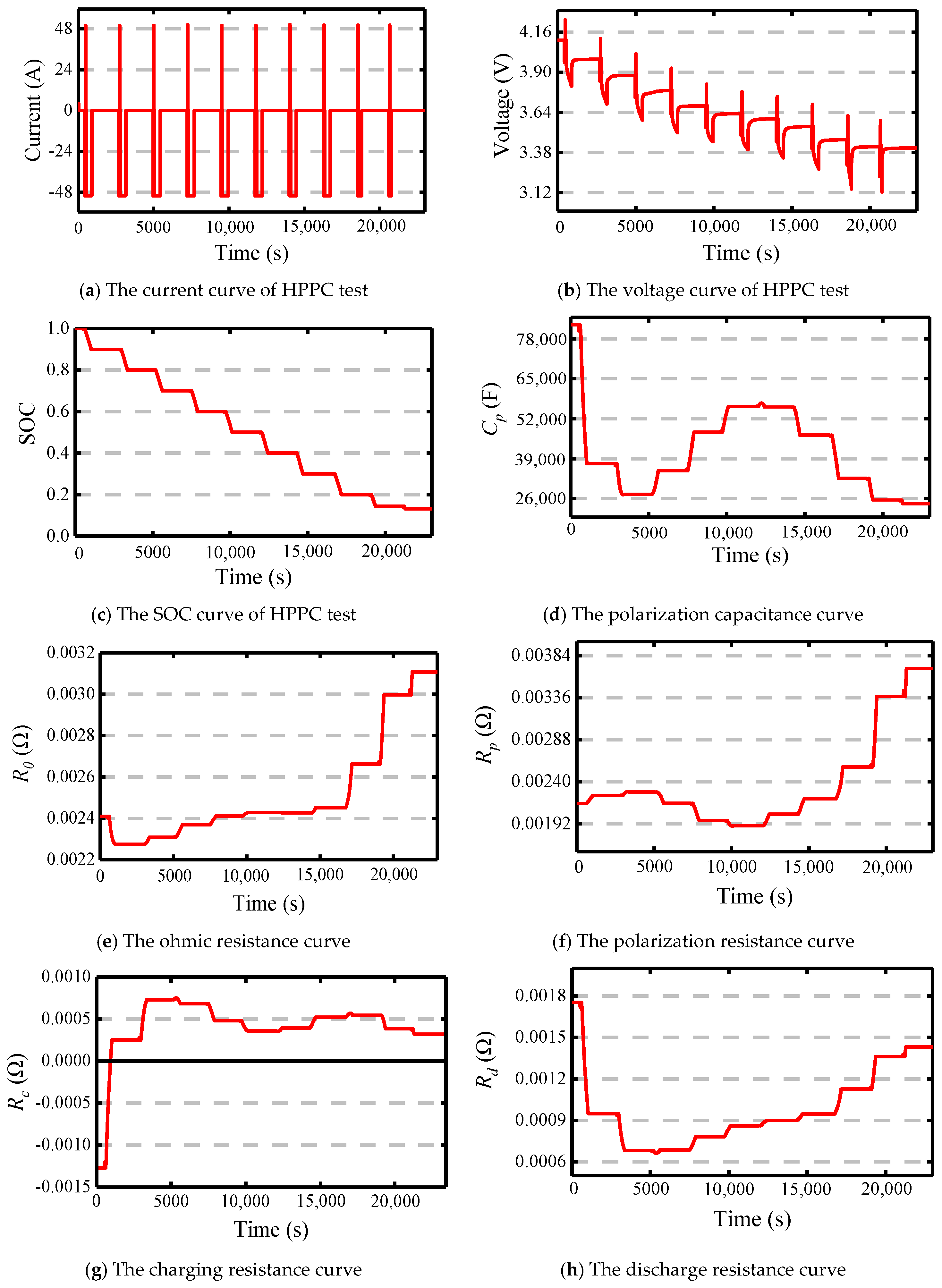
4.1. Experimental Platform

In order to verify the above theoretical analysis, this paper selects an experimental sample of a lithium-ion battery with an actual capacity of 50 Ah to verify the accuracy and robustness of the above battery model and SOC estimation strategy. The structure of the experimental device is shown in Figure 6.
In order to obtain the value of the internal charge resistance and the internal discharge resistance of the IR-PCM, the intermittent charging experiment and the intermittent discharging experiment are carried out on the above-mentioned experimental platform using the selected battery samples. The experimental steps are as follows.
Step 1
Fully charge the LiB samples.
Step 2
Discharge the LiB samples to an SOC of 0.9 with 1 C current and let it stand for 40 min, use a high-precision internal resistance measuring instrument to measure the internal resistance of the LiB samples and record it.
Step 3
Discharge the battery again for another six minutes with a current of 1 C to reduce the LiB samples SOC to 0.8. Let it stand for 40 min.
Step 4
Repeat step 2 until the battery SOC drops to 0.1.
The procedure of the charge experiment is the almost same as that of the discharge experiment, except that it is charge instead of discharge and that the SOC increases from 0.1 to 1. The battery internal resistance obtained from the two experiments is shown in Table 1.

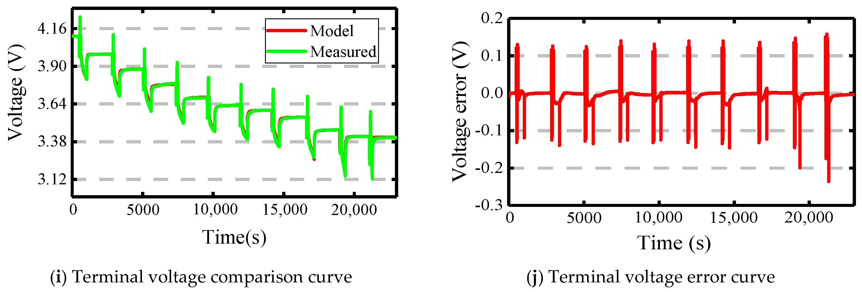
4.2. Modeling Verification

In order to verify the terminal voltage tracking effect of the IR-PCM, based on FFRLS algorithm in Figure 2 and combined with HPPC experiment, online parameter identification of lithium-ion battery is realized. The full parameter identification result based on the combination of FFRLS and IR-PCM is shown in Figure 7.
As shown in Figure 7, online parameter identification is performed for the lithium-ion battery by using the FFRLS algorithm. Figure 7a–c shows the current curve, the voltage curve, and the SOC curve of the HPPC test. Figure 7d shows the polarization internal resistance curve of the battery. It can be seen by comparing Figure 7e,f that the ohm internal resistance is always greater than the battery charge-discharge internal resistance throughout the HPPC process, and the ohm internal resistance is greater than the polarization internal resistance during the initial and middle periods of the discharge. In Figure 7g, an outlier with negative internal resistance of charging appears during parameter identification, which is found to be caused by system error through data study. When the SOC becomes 0.2 during the discharge, the ohmic internal resistance and the polarization internal resistance start to increase and the latter is greater than the former. What is more, during charge, lithium ions move from the positive pole to the negative pole and there are remaining transition metal oxides in the positive pole, resulting in greater resistance, due to the different materials of the positive and negative poles. During the discharge, there are lithium oxides on the positive pole and the resistance is small, as shown in Figure 7g,h. The above-mentioned online parameter identification result is used to verify IR-PCM accuracy. The result is shown in Figure 7i,j. During the HPPC experiment, IR-PCM’s estimation values for the battery terminal voltage can perfectly track the actual values. Based on the terminal voltage estimation errors in Figure 7j, the terminal voltage changes suddenly upon the current pulse arrival. As a result, the deviation between the experimental value and the simulation value increases to 0.1 V to 0.2 V. Otherwise, the terminal voltage simulation value and the terminal voltage experimental value remain basically consistent when the SOC of LiB is between 10% and 100%, with the overall error smaller than 0.035 V, which is 0.9% of the nominal voltage. This indicates that the improved IR-PCM is reasonable, and the identification precision of the FFRLS algorithm is high.

4.3. BBDST Working Condition Experimental Verification

In order to verify the accuracy and robustness of the new AF-DKF, based on the HPPC experimental data, based on the results of the above-mentioned full parameter identification, the BBDST operating condition experiment was further carried out on the LiB samples. Besides, the proposed algorithm and the pre-improvement AEKF and F-UKF algorithms were compared. The relevant experimental index curve of BBDST is shown in Figure 8.
Figure 8a shows the BDDST current curve and Figure 8b shows the diagram of the output voltage and SOC under the BDDST working condition. Figure 8c,d show the SOC comparison curve and SOC error curve under different estimation algorithms, where 1 is the normalized unit of the parameter. Based on the BDDST experiment result, the following conclusions are drawn:
(1)
With violent changes of the operating current, the errors of the three algorithms remain within 0.4% when the SOC value is between 0.9 and 1 and converge in a relatively proper manner on the theoretical SOC value.
(2)
With the further progress the BDDST working condition, the error of the AEKF algorithm starts to increase, with a maximum of 0.8%, when the SOC value is between 0.8 and 0.9, while those of F-UKF and AF-DKF are still within 0.4% and can still converge in a relatively proper manner on the theoretical SOC value. Besides, the value of AF-DKF is smaller than that of F-UKF. Due to the Taylor truncation error of the AEKF algorithm, the error of the algorithm increases in the later stage of the SOC estimation, and even leads to the divergence of the filtering. The iterative results of F-UKF algorithm and AF-DKF algorithm are globally optimal, and the possibility of filtering divergence is greatly reduced.
(3)
When SOC reduces to less than 0.8, the situation is as follows: the error of AEKF increases obviously, with a maximum of over 1.5%. With the progress of the experiment, there is a possibility of divergence for AEKF, indicating that it has relatively poor robustness. For F-UKF and AF-DKF, the SOC estimation fluctuates, with the maximum error of F-UKF increasing to 0.5% and that of AF-DKF still within 0.4%.
It can also be seen from the above SOC estimation error results that the maximum SOC estimation error of the AF-DKF algorithm is 0.5%, which is 1.8% higher than the unscented particle filter algorithm used in reference [33] (the maximum estimation error of SOC is 2.3%). In addition, compared to the iterative strategy of combining EKF and adaptive UKF used in reference [34] (the maximum estimation error of SOC is 0.9%), the accuracy of the AF-DKF algorithm proposed in this paper is increased by 0.4%. The AF-DKF algorithm combines the advantages of the AEKF algorithm and the F-UKF algorithm. In the iterative process, not only is the robustness significantly enhanced, but the accuracy is also significantly improved.

5. Conclusions

In order to improve SOC identification accuracy and BMS robustness, EKF is improved through adding an adaptive noise tracking algorithm to improve system stability and the Kalman gain in the UKF algorithm is improved by introducing a dynamic Equation to improve system accuracy. In addition, FFRLS and the above-mentioned two improved algorithms are combined to propose a new AF-DKF algorithm in this paper, which uses alternate operation of AEKF and F-UKF and gives the system higher estimation accuracy. The model and algorithm accuracy is verified through HPPC and BBDST working condition experiments. This indicates that the accuracy and robustness of AF-DKF is better than that of AEKF and F-UKF. Future work will focus on BMS R&D based on this algorithm.

Author Contributions

Y.F. planned the initial idea and developed the modelling framework. H.S. de-signed the algorithm. Y.F. and S.W. analyzed the experimental date and wrote the original manuscript. W.C. and J.H. established the experiment bench. C.F. revised the final manuscript. All authors have read and agreed to the published version of the manuscript.

Funding

This research was funded by [National Natural Science Foundation] grant number [61801407], [Sichuan Science and Technology Program] grant number [2021YFG0253], [Science and Technology Planning Project of Mianyang] grant number [2019YFZJ007] and [Natural Science Foundation of Southwest University of Science and Technology] grant number [17ZX7110].

Institutional Review Board Statement

Not applicable.

Informed Consent Statement

Not applicable.

Data Availability Statement

Data used in drafting of this article are available at https://www.researchgate.net/lab/DTlab-Shunli-Wang (accessed on 20 June 2020).

Acknowledgments

Thanks to the sponsors. C. F. would like to express his gratitude to RGU for its support.

Conflicts of Interest

The authors declare no conflict of interest.

Nomenclature

Notation
Iloop current
ULterminal voltage
Eideal voltage source
Uocopen circuit voltage
Rppolarization resistance
Cppolarization capacitance
Rcdinternal resistance
ε1Coulomb efficiency
ε2temperature influence coefficient
QNbattery capacity
θcoefficient vector
φdata vector
ζparameter matrix
λforgetting factor
ηgain matrix of FFRLS
Rnmixed resistance value
wkprocess noise
vkobservation noise
KAEKF,kgain matrix of AEKF
σ forgetting factor of AEKF
e k innovation of AEKF
Δ I max set value for the maximum current change
Δ t sampling time interval
γ weight factor of F-UKF
KF-UKF,kgain matrix of F-UKF
ϕdynamic function
SOCTF,kinitial SOC value of F-UKF
SOCAEKF,kestimate of SOC under AEKF
SOCF-UKF,kestimate of SOC under F-UKF
SOCAF-DKF,kestimate of SOC under AF-DKF
h(x)random number following normal distribution
ϖ * weight factors of AF-DKF
Acronyms & abbreviations
EVselectric vehicles
BMSbattery management system
SOCState-of-charge
EKFextended Kalman filter
PFparticle filter
AIartificial intelligence
RCresistance-capacitance
UKFunscented Kalman filter
SOHstate-of-health
RLSrecursive least square
FFRLSforgetting factor recursive least square
AEKFadaptive extended Kalman filter
F-UKFfunction—unscented Kalman filter
AF-DKFadaptive function—dual Kalman filter
BBDSTBeijing bus dynamic stress test
OCVopen circuit voltage
SISOsingle-input single-output
ARMAautoregressive moving average

References

  1. Hu, X.S.; Zou, C.F.; Zhang, C.P.; Li, Y. Technological developments in batteries: A survey of principal roles, types, and management needs. IEEE Power Energy Mag. 2017, 15, 20–31. [Google Scholar] [CrossRef]
  2. Ouyang, M.G.; Du, J.Y.; Peng, H.E.; Wang, H.W.; Feng, X.N.; Song, Z.Y. Progress review of US-China joint research on advanced technologies for plug-in electric vehicles. Sci. China Technol. Sci. 2018, 61, 1431–1445. [Google Scholar] [CrossRef]
  3. Wei, Z.B.; Zhao, J.Y.; Zou, C.F.; Lim, T.M.; Tseng, K.J. Comparative study of methods for integrated model identification and state of charge estimation of lithium-ion battery. J. Power Sources 2018, 402, 189–197. [Google Scholar] [CrossRef]
  4. Wang, S.L.; Fernandez, C.; Liu, X.H.; Su, J.; Xie, Y.X. The parameter identification method study of the splice equivalent circuit model for the aerial lithium-ion battery pack. Meas. Control 2018, 51, 125–137. [Google Scholar] [CrossRef] [Green Version]
  5. Stübler, T.; Lahyani, A.; Zayoud, A.A. Lithium-ion battery modeling using CC–CV and impedance spectroscopy characterizations. SN Appl. Sci. 2020, 2, 1–8. [Google Scholar] [CrossRef] [Green Version]
  6. Couto, L.D.; Schorsch, J.; Job, N.; Leonard, A.; Kinnaert, M. State of health estimation for lithium ion batteries based on an equivalent-hydraulic model: An iron phosphate application. J. Energy Storage 2019, 21, 259–271. [Google Scholar] [CrossRef]
  7. Barai, A.; Uddin, K.; Widanage, W.D.; McGordon, A.; Jennings, P. A study of the influence of measurement timescale on internal resistance characterisation methodologies for lithium-ion cells. Sci Rep. UK 2018, 8, 21. [Google Scholar] [CrossRef]
  8. Yang, J.F.; Xia, B.; Shang, Y.L.; Huang, W.X.; Mi, C.C. Adaptive state-of-charge estimation based on a split battery model for electric vehicle applications. IEEE Trans. Veh. Technol. 2017, 66, 10889–10898. [Google Scholar] [CrossRef]
  9. Mesbahi, T.; Rizoug, N.; Bartholomeus, P.; Sadoun, R.; Khenfri, F.; Le Moigne, P. Dynamic model of li-ion batteries incorporating electrothermal and ageing aspects for electric vehicle applications. IEEE Trans. Ind. Electron. 2018, 65, 1298–1305. [Google Scholar] [CrossRef]
  10. Ma, Y.; Duan, P.; Sun, Y.S.; Chen, H. Equalization of Lithium-ion Battery Pack based on Fuzzy Logic Control in Electric Vehicle. IEEE Trans. Ind. Electron. 2018, 65, 6762–6771. [Google Scholar] [CrossRef]
  11. Wang, S.L.; Shang, L.P.; Li, Z.F.; Deng, H.; Li, J.C. Online dynamic equalization adjustment of high-power lithium-ion battery packs based on the state of balance estimation. Appl. Energy 2016, 166, 44–58. [Google Scholar] [CrossRef]
  12. Zhang, Z.Y.; Zhang, L.Z.; Hu, L.; Huang, C.X. Active cell balancing of lithium-ion battery pack based on average state of charge. Int. J. Energy Res. 2020, 44, 2535–2548. [Google Scholar] [CrossRef]
  13. Mathew, M.; Janhunen, S.; Rashid, M.; Long, F.; Fowler, M. Comparative analysis of lithium-ion battery resistance estimation techniques for battery management systems. Energies 2018, 11, 1490. [Google Scholar] [CrossRef] [Green Version]
  14. Lee, C.; Said, A.O.; Stoliarov, S.I. Impact of state of charge and cell arrangement on thermal runaway propagation in lithium-ion battery cell arrays. Transp. Res. Rec. 2019, 2673, 408–417. [Google Scholar] [CrossRef]
  15. Han, X.B.; Ouyang, M.G.; Lu, L.G.; Li, J.Q. Simplification of physics-based electrochemical model for lithium-ion battery on electric vehicle. Part II: Pseudo-two-dimensional model simplification and state of charge estimation. J. Power Sources 2015, 278, 814–825. [Google Scholar] [CrossRef]
  16. Lee, K.T.; Dai, M.J.; Chuang, C.C. Temperature-Compensated Model for Lithium-Ion Polymer Batteries with Extended Kalman Filter State-of-Charge Estimation for an Implantable Charger. IEEE Trans. Ind. Electron. 2018, 65, 589–596. [Google Scholar] [CrossRef]
  17. Xu, Y.D.; Hu, M.H.; Zhou, A.J.; Li, Y.X.; Li, S.X.; Fu, C.Y.; Gong, C.C. State of charge estimation for lithium-ion batteries based on adaptive dual Kalman filter. Appl. Math. Modell. 2020, 77, 1255–1272. [Google Scholar] [CrossRef]
  18. Shen, P.; Ouyang, M.G.; Lu, L.G.; Li, J.Q.; Feng, X.N. The co-estimation of state of charge, state of health, and state of function for lithium-ion batteries in electric vehicles. IEEE Trans. Veh. Technol. 2018, 67, 92–103. [Google Scholar] [CrossRef]
  19. Chen, X.K.; Lei, H.; Xiong, R.; Shen, W.X.; Yang, R.X. A novel approach to reconstruct open circuit voltage for state of charge estimation of lithium ion batteries in electric vehicles. Appl. Energy 2019, 255, 113758. [Google Scholar] [CrossRef]
  20. Luo, M.J.; Guo, Y.Z.; Kang, J.Q.; She, L.Y.; Geng, Z.C. Ternary-material lithium-ion battery SOC estimation under various ambient temperature. Ionics 2018, 24, 1907–1917. [Google Scholar] [CrossRef]
  21. Zhang, Z.L.; Cheng, X.; Lu, Z.Y.; Gu, D.J. SOC estimation of lithium-ion battery pack considering balancing current. IEEE Trans. Power Electron. 2018, 33, 2216–2226. [Google Scholar] [CrossRef]
  22. Wang, S.L.; Fernandez, C.; Chen, M.J.; Wang, L.; Su, J. A novel safety anticipation estimation method for the aerial lithium-ion battery pack based on the real-time detection and filtering. J. Cleaner Prod. 2018, 185, 187–197. [Google Scholar] [CrossRef]
  23. Wang, Y.J.; Zhang, C.B.; Chen, Z.H. A method for state-of-charge estimation of LiFePO4 batteries at dynamic currents and temperatures using particle filter. J. Power Sources 2015, 279, 306–311. [Google Scholar] [CrossRef]
  24. Liu, S.Q.; Xu, D.P.; Ma, T.Y.; Wei, Z.; Lin, C.J.; Bai, G.L.; Gao, X.L.; Shen, J.J.; Huang, W.L.; Wang, F.; et al. Thermal safety studies of high energy density lithium-ion batteries under different states of charge. Int. J. Energy Res. 2020, 44, 1535–1545. [Google Scholar] [CrossRef]
  25. Afshari, H.H.; Attari, M.; Ahmed, R.; Delbari, A.; Habibi, S.; Shoa, T. Reliable state of charge and state of health estimation using the smooth variable structure filter. Control Eng. Pract. 2018, 77, 1–14. [Google Scholar] [CrossRef]
  26. Wang, W.D.; Wang, X.T.; Xiang, C.L.; Wei, C.; Zhao, Y.L. Unscented Kalman Filter-Based Battery SOC Estimation and Peak Power Prediction Method for Power Distribution of Hybrid Electric Vehicles. IEEE Access 2018, 6, 35957–35965. [Google Scholar] [CrossRef]
  27. Tian, J.P.; Xiong, R.; Yu, Q.Q. Fractional-Order Model-Based Incremental Capacity Analysis for Degradation State Recognition of Lithium-Ion Batteries. IEEE Trans. Ind. Electron. 2019, 66, 1576–1584. [Google Scholar] [CrossRef]
  28. Kim, M.; Kim, K.; Kim, J.; Han, S. State of Charge Estimation for Lithium-ion battery Based on Reinforcement Learning. IFA Pap. OnLine 2018, 51, 404–408. [Google Scholar] [CrossRef]
  29. Li, H.H.; Zhang, W.; Yang, X.R.; Jiang, H.B.; Wang, Y.P.; Yang, T.; Chen, L.; Shen, H.P. State of charge estimation for lithium-ion battery using an electrochemical model based on electrical double layer effect. Electrochim. Acta 2019, 326, 134966. [Google Scholar] [CrossRef]
  30. Stenzel, Y.P.; Borner, M.; Preibisch, Y.; Winter, M.; Nowak, S. Thermal profiling of lithium-ion battery electrodes at different states of charge and aging conditions. J. Power Sources 2019, 433, 226709.1–226709.11. [Google Scholar] [CrossRef]
  31. Wang, Y.J.; Liu, C.; Pan, R.; Chen, Z.H. Modeling and state-of-charge prediction of lithium-ion battery and ultracapacitor hybrids with a co-estimator. Energy 2017, 121, 739–750. [Google Scholar] [CrossRef]
  32. Long, H.Y.; Zhu, C.Y.; Huang, B.B.; Sun, Y.Q. Model parameters online identifcation and SOC joint estimation for lithium-ion battery based on a composite algorithm. J. Electr. Eng. Technol. 2019, 14, 1485–1493. [Google Scholar] [CrossRef]
  33. Wang, Y.J.; Chen, Z.H. A framework for state-of-charge and remaining discharge time prediction using unscented particle filter. Appl. Energy 2020, 260, 114324. [Google Scholar] [CrossRef]
  34. Duan, W.X.; Song, C.X.; Chen, Y.; Xiao, F.; Peng, S.L.; Shao, Y.L.; Song, S.X. Online Parameter Identification and State of Charge Estimation of Battery Based on Multitimescale Adaptive Double Kalman Filter Algorithm. Math. Probl. Eng. 2020, 2020, 9502605. [Google Scholar] [CrossRef]
Figure 1. Internal resistance—polarization circuit model.
Energies 14 02268 g001
Figure 2. Diagram of the general structure of online parameter identification based on FFRLS.
Energies 14 02268 g002
Figure 3. AEKF algorithm to estimate SOC flow chart.
Energies 14 02268 g003
Figure 4. F-UKF algorithm iteration principle diagram.
Energies 14 02268 g004
Figure 5. AF-DKF algorithm flow chart.
Energies 14 02268 g005
Figure 6. Battery test platform.
Energies 14 02268 g006
Figure 7. Full parameter identification result based on the IR-PCM model.
Energies 14 02268 g007aEnergies 14 02268 g007b
Figure 8. The BBDST experiment index curves.
Energies 14 02268 g008
Table 1. Measurement results of battery internal resistance.
SOC (%)1.00.90.80.70.60.50.40.30.20.1
The charging resistance (mΩ)2.23442.53363.03963.06662.91432.78852.80262.97743.23903.3854
The discharge resistance (mΩ)4.18103.23142.99023.07023.21313.29173.30863.39753.82204.4957
Publisher’s Note: MDPI stays neutral with regard to jurisdictional claims in published maps and institutional affiliations.

