Abstract
This paper presents a multi-objective optimal rotor design for an interior permanent magnet synchronous motor (IPMSM) based on finite element analysis. Due to the importance of torque characteristic in electromagnetic design of IPMSMs, the main efforts of this study are focused on finding a proper trade-off for its torque profile challenges. In this regard, in order to attain high average torque and low torque ripple, the influence of several key factors, such as the permanent magnet (PM) arrangements, PM positions and PM sizes, are examined. Subsequently, according to the outcomes of the performed sensitivity analysis, the appropriate variation interval of the parameters as well as their initial values is determined. Employing such a deterministic optimization algorithm, which does not need large sample points, minimizes the finite element computational cost and leads to accelerate the convergence process. The two-dimensional finite element model (FEM) of an IPMSM is used to perform a sensitivity analysis and establish a multi-objective FEM-based optimization.
1. Introduction
Due to the rapid development and implementation of Nd-Fe-B magnets, IPMSMs play a significant role in many industrial applications [1,2]. IPMSMs provide a high torque density, high reluctance torque, appropriate flux weakening capability, high efficiency and simple controllability [3,4,5]. In some cases, such as traction applications in which IPMSMs are promising electric machines, high torque density and low torque ripple because of the influence on the comfort and the stability of vehicle play a vital role; thus, a trade-off between the average torque and torque ripple should be taken into consideration [6,7,8,9,10]. The developed torque in these machines is intensively affected by the parameters such as magnets size and magnets position [11,12]. Hence, a multi-objective optimal design of IPMSM is indispensable.
Owing to progress in computational ability in optimization problems, FEM-based optimization has gotten more attention for accurate design optimization of electric machines [13,14]. Some recent multi-objective optimization methods of IPMSMs have been studied based on finite element analysis in [15,16,17,18,19,20,21].
Reference [15] proposed a finite-element based multi-objective optimization procedure using a new algorithm belonging to the class of controlled random search algorithms for minimizing weight and maximizing power output. Moreover, the torque ripple optimization has been ignored. References [16,17], using deep learning techniques, presents some fast optimization methods for IPMSMs; however, the side PMs effect was not considered. In [18], torque ripples were optimized in IPMSMs using a multi-island genetic algorithm, radial basis function neural networks and the orthogonal experimental method; however, no effort was made to optimize the developed torque. In [19], a multi-objective stratified optimization strategy is proposed, where five optimization objectives are divided into two levels consisting of priority level 1 (output torque, PM cost) and level 2 (cogging torque, torque ripple, efficiency); however, though an important design parameter, PM’s position relative to the rotor center has been ignored. In [20], by combining the PSO algorithm with mesh adaptive direct search and applying it to the design of an IPMSM, torque ripple was minimized while the PM’s angle and the average torque were not considered. In [21], an effective multilevel optimization strategy using the Pearson correlation coefficient analysis and cross-factor variance analysis for high-dimensional multi-objective optimization design of an IPMSM was proposed; however, only the V structure has been considered and PMs position relative to rotor center has been neglected. In [22,23,24,25,26], novel rotor types have been proposed for the performance improvement of IPMSMs. However, the manufacturing of the novel rotor made it more complicated and more expensive than the conventional rotors.
The complexity of optimization grows with excess objective functions, design parameters and inappropriate design parameters variation interval; therefore, in this study, an effective multi-objective optimal design method for IPMSMs has been presented. First, by using the finite element method, we investigated the influence of various design parameters, such as magnet width and thickness, the position of the central magnet relative to the rotor center, side magnet width and thickness and side magnet angle on the average torque and torque ripple. Then, an initial state based on the results obtained from the sensitivity analysis was determined for optimization. Finally, using the optimization toolbox of ANSYS-Maxwell and the BFGS method, which does not need huge finite element analysis attempt, the optimization problem was run.
2. Methodology for the Optimal Design of IPMSM
IPMSMs are worthy candidates for electric traction systems because of the advantages that it presents. This research work deals with the train traction system. The purpose is a multi-objective optimal design of IPMSM, which is explained in detail in this section. Prior to presenting the electromagnetic design of the motor, it is worth to briefly describe the simplified train motion equations. Examination of the train motion equations is indispensable for sizing the electric motor served to develop the propulsive force. Furthermore, the desired performance of the train during acceleration and during steady state operation affects the electromagnetic design of the electric traction motor. Since in this research work the focus is placed on electromagnetic design of the traction motor, the train motion equations and the desired performance of the train are simplified as much as possible. In the following, the train motion specifications are provided.
2.1. Train Specifications and Equations
Train motion specifications are listed in Table 1.

Table 1.
Train motion specifications.
The initial design corresponding to the train specifications was carried out based on the train motion equations. Based on the train motion equations and the provided train specifications, the rated speed was determined. Subsequently, the rated torque of the traction motor was calculated. A simple electric traction system is illustrated in Figure 1.
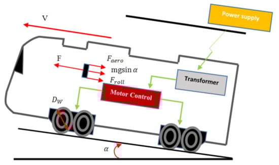
Figure 1.
Electric traction system.
Based on Newton’s law, the main equation of train motion can be written as Equation (1):
where m, v, F and stand for the train mass per a traction motor, linear speed of the train, propulsive force due to a traction motor and resistant force, respectively. The aerodynamic resistant force and rolling resistant force are expressed as Equations (2) and (3), respectively [27]:
where ρ, , , , α, g and µ denote the air mass density, train aerodynamic coefficient, train surface exposed to the head wind, head wind velocity, slope angle of the motion path, gravity acceleration and rolling resistance coefficient train wheel relative to the rail, respectively. Here, the effect of head wind is neglected.
The resistance force can be calculated by Equation (4):
By substituting Equations (2)–(4) in Equation (1), the acceleration time could be calculated. The train on its determined operation accelerates from a stationary state to a steady state speed and continues on this speed. Hence, the steady state speed was treated as its maximum speed. It should be noted that lower than the rated speed, the maximum torque is constantly exerted on the train by traction motors. Moreover, over the rated speed, the exerted torque is proportional to the inverse of the train speed; in other words, when the train goes slower than the rated speed, we obtain the maximum torque per ampere control, while when going over the rated speed, maximum power control is applied on the traction motor. The traction performance curve is depicted in Figure 2. Thus, the train acceleration time can be expressed as in Equation (5):
where Vn and Pn refer to the rated train speed and the rated propulsive power per traction motor, respectively.
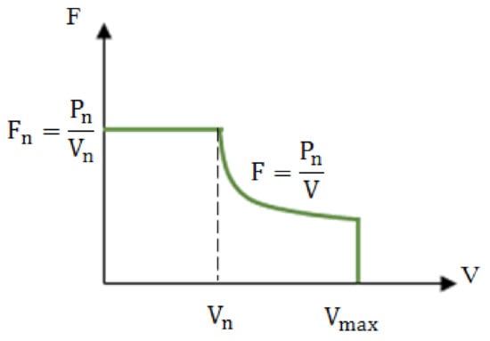
Figure 2.
Traction performance curve.
According to the specifications provided in Table 1 and the presented relations in this part, the rated speed of the traction motor in terms of rpm is determined by Equation (6), where Dw and GR stand for the train rated linear speed and the gear ration, respectively:
In this research work, for the sake of simplicity, the rated linear speed of the train is considered equal to its steady state speed. Consequently, the rated speed of the traction motor is equal to 2369 rpm.
2.2. Rotor Optimization Method
In this research work, during the optimization, the focus is placed on the rotor. In this respect, the stator specifications are kept fixed, as summarized in Table 2. However, at the end of optimization and after achieving the optimized structure, the average torque would be improved compared with that obtained from the basic design. Hence, we would be able to reduce the motor length. In other words, although the focus during the optimization is placed on the rotor structure, the optimized structure allows us to reduce the stator length.
Table 2.
Stator specification of the studied IPMSM.
The design structure of considered IPMSM has been illustrated by Figure 3. Additionally, the stator specifications have been tabulated in Table 2. It should be noted that during the design procedure, the motor is fed by the sinusoidal current.
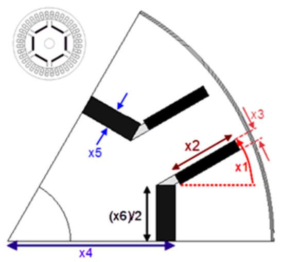
Figure 3.
Proposed structure of the IPMSM and optimization variables.
Based on the structure presented in Figure 3, selected parameters for multi-objective optimal design of rotor include the side magnet angle (x1), side magnet width (x2), side magnet thickness (x3), central magnet position relative to rotor center (x4), central magnet thickness (x5) and central magnet width (x6). Due to the symmetric properties, one pole pitch of the proposed structure for IPMSM is depicted in Figure 3.
By accurately investigating the sensitivity of the average torque and torque ripple relative to the rotor parameters, besides the initial state of the optimization algorithm, the appropriate variation intervals for the rotor parameters are chosen.
3. Sensitivity Analysis
In order to investigate the effect of the rotor parameters on the average torque and torque ripple, the specified optimization parameters are varied according to the intervals indicated in Table 3.
Table 3.
Variation interval of the rotor parameters for the sensitivity analysis and optimization algorithm.
The sensitivity analysis of the average torque and the torque ripple relative to the rotor parameters are illustrated in Figure 4, Figure 5, Figure 6, Figure 7, Figure 8 and Figure 9.
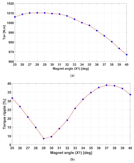
Figure 4.
Impact of the side magnet angle variation on: (a) the average torque; (b) the torque ripple.
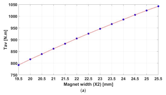
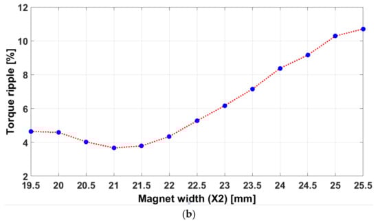
Figure 5.
Impact of the side magnet width variation on: (a) the average torque; (b) the torque ripple.
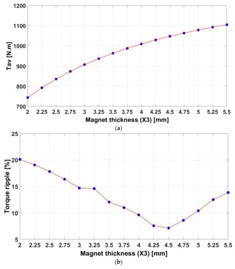
Figure 6.
Impact of the side magnet thickness variation on: (a) the average torque; (b) the torque ripple.
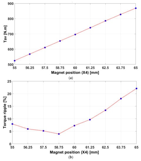
Figure 7.
Impact of the central magnet position variation relative to the rotor center on: (a) the average torque; (b) the torque ripple.
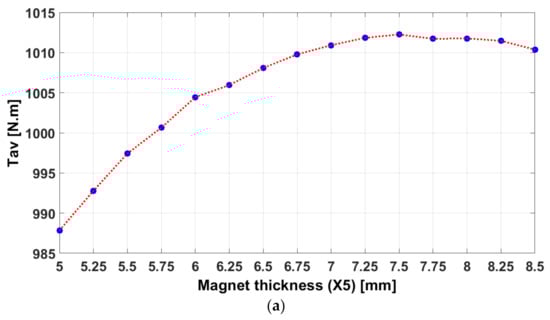
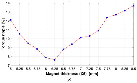
Figure 8.
Impact of the central magnet thickness variation on: (a) the average torque; (b) the torque ripple.
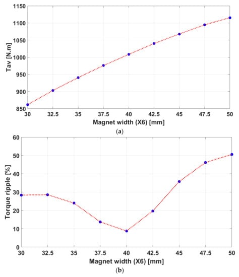
Figure 9.
Impact of the central magnet width variation on: (a) the average torque; (b) the torque ripple.
Since the purpose of optimal design is to maximize the average torque and to minimize the torque ripple, determining the appropriate variation interval for all of parameters is required. For example, in case of a side magnet angle, it can be observed that the points corresponding to the maximum average torque and minimum torque ripple approximately coincide with each other. Hence, it is obvious that the optimal value for the side magnet angle is located in the immediate vicinity of the points corresponding to the maximum average torque and minimum torque ripple. According to Figure 8a,b, it can be seen that as the central magnet thickness is stepped up, the average torque is stepped up, and consequently, it saturates. The torque ripple also consists of a minimum value as the side magnet thickness increases. In this case, since the points corresponding to the average torque knee value and the minimum of the torque ripple coincide with each other, the proper variation interval for the central magnet thickness for the optimization process would be determined around the knee point of the average torque. In case of other parameters, regarding the increment rate or decrement rate of the average torque and torque ripple, the appropriate corresponding parameter variation for the optimization algorithm could be determined.
Prior to the determination of the objective function, we carried out a sensitivity analysis. By performing this sensitivity analysis, an appropriate initial point for the optimization algorithm was determined. In order to define an objective function, including the average torque and the torque ripple, which do not have the same unity, we need to use their normalized values. To obtain these normalized values, a sensitivity analysis was carried out. By exploiting the outcomes of the sensitivity analysis, the search space for the optimization procedure was reduced, which accelerate the convergence.
4. Multi-Objective Optimal Design of the Rotor
4.1. Objective Function and Optimization Variables
In this research work, maximizing the average torque and minimizing the torque ripple were considered as the objectives. In traction applications, because of the restriction in space, we need to use an electric motor with high torque density. To this end, we need to maximize the average torque. On the other hand, in traction applications, we desire to reduce the torque ripple to avoid producing extra noise. Hence, defining an objective function with the aim of maximizing the average torque and minimizing the torque ripple would be appropriate. Since the purpose of an optimal design is to maximize the average torque and to minimize the torque ripple, the objective function is proposed in Equation (7):
where W1 and W2 stand for the weighting value of the average torque and the torque ripple, which are set at 1 and 2 by priority to torque ripple minimization, respectively, G1 and G2 refer to the desired value of the normalized average torque and the normalized torque ripple, respectively, Tav denotes the average torque and Tripple denotes the torque ripple, which is calculated with Equation (8):
The objective of the proposed optimization strategy is to maximize the average torque and minimize the torque ripple simultaneously. To this end, we need to define a cost function in such a way that minimizing the cost function results in maximizing the average torque and minimizing the torque ripple. Based on the defined cost function (see Equation (7)), as the normalized average torque and the normalized torque ripple approach to G1 and G2, respectively, the value of the cost function decreases.
Furthermore, since the average torque and the torque ripple do not have the same unity, we have employed their normalized values. In this research work, G1 = 10 and G2 = 1 have been chosen arbitrarily. After assigning the mentioned values to G1 and G2, the normalized value of the average torque and torque ripple are defined in such a way that they attain the values between 1 and 10 during the optimization procedure.
The normalized values of the average torque and the torque ripple are expressed by using Equations (9) and (10), respectively:
The normalized average torque and normalized torque ripple are determined in such a way that they take values between G1 = 1 and G2 = 10. We remind the reader that the values of G1 and G2 were chosen arbitrarily. In accordance with the variation interval of the rotor parameters indicated in Table 3, the average torque can approximately vary from 900 Nm up to 1100 Nm, whereas the torque ripple can approximately vary between 3% and 20%. Hence, in the cases where the average torque attains 900 Nm and 1100 Nm, the normalized average torque is equal to 1 and 10, respectively (in accordance with Equation (9)). When the torque ripple takes 3% and 20%, the normalized torque ripple attains 1 and 10, respectively (in accordance with Equation (10)).
4.2. Multi-Objective Optimization by the BFGS Method
The BFGS optimization method, which is suitable for large-scale numerical optimization [28], carries out the optimization based on the second order Taylor expansion of multivariable function f at the vicinity of vector Xk, which is presented in Equation (11) [29]:
where is the model function whose behavior at the vicinity of the current point Xk is similar to that of the actual objective function f. As the notation indicates, fk and are chosen to be the function and the gradient values at the point Xk, respectively, and P stands for the search direction. Thus, for any point X, P is defined by . βk is defined as (Hessian Matrix of f in Kth iteration). fk and are the scalar and vector, respectively. By applying the gradient operator to both sides of Equation (11), the minimum point can be stated as follows (Equation (12)):
where Pk stands for the search direction in the kth iteration in order to calculate P0; assuming H0 = I could be acceptable. Equation (13) represents the updating relation that is exerted on the optimizer variables, where αk is determined by the line search:
Xk+1 = Xk + αk Pk
By defining Sk and Yk as Equations (14) and (15), respectively, the inverse of the Hessian matrix in the iteration of k + 1 is updated by Equation (16), which is known as the Sherman-Morrison formula:
4.3. Optimization Result
The initial states for the optimization algorithm are the values assigned to the basic design, which are obtained by sensitivity analysis and are tabulated in Table 4. Moreover, the outcomes of optimization are demonstrated in Figure 10. As can be seen, the torque ripple is reduced by 64% and the torque average is increased from 1008 Nm to 1093 Nm. Figure 10 illustrates the electromagnetic torque of the optimal and basic design. No-load air gap flux density distribution for one pole pith (60 deg mechanical) and no-load flux linkage for the optimized structure are illustrated in Figure 11 and Figure 12, respectively. The represented air gap flux density distribution corresponds to the structure illustrated in Figure 3.
Table 4.
Optimization results.
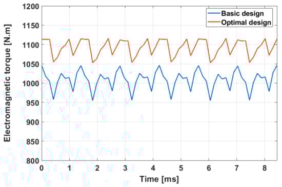
Figure 10.
Electromagnetic torque corresponding to the basic design and the optimal design.
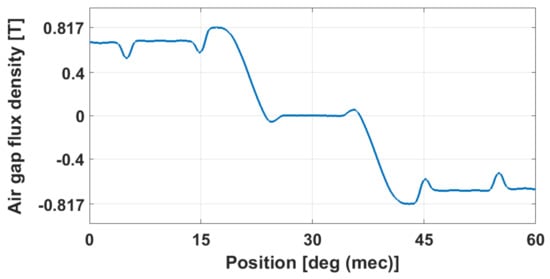
Figure 11.
Air gap flux density distribution for one pole pitch of the optimized structure.
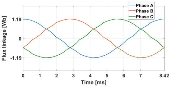
Figure 12.
Stator winding flux linkage for the optimized structure.
It should be noted that the BFGS method cannot ensure finding the global extremum of a function, but it is able to localize the local minima or local maxima.
By comparing the variation intervals of the average torque and torque ripple obtained from the sensitivity analysis with the results attained from the optimization method, we can conclude that achieving an average torque of 1093 Nm and a torque ripple of 5.82% is satisfactory.
5. Conclusions
In this paper, a multi-objective optimal rotor design of an IPMSM with the aim of maximizing the average torque and minimizing the torque ripple has been presented. In this regard, the BFGS method was employed for optimization. In contrast to the metaheuristic optimization methods, which require many sample points, the BFGS method is based on a single initial guess. This method can be appropriate for the applications where FEM is applied. In order to determine the range of optimization variables and assign the initial state of the optimization algorithm, a sensitivity analysis was performed and the finite element method was used as an analysis tool. During the sensitivity analysis, the impacts of the permanent magnets’ position and dimension on the average torque and torque ripple were studied. This sensitivity study allowed us to determine an appropriate initial state as well as a restrictive variation range for the optimization strategy. The proposed method can be generalized for the other IPMSMs topologies.
Author Contributions
Conceptualization, S.A., T.L., A.V. and N.T.; methodology, S.A., T.L., A.V. and N.T.; software, S.A., T.L., A.V. and N.T.; validation, S.A., T.L., A.V. and N.T.; formal analysis, S.A., T.L., A.V. and N.T.; investigation, S.A., T.L., A.V. and N.T.; resources, S.A., T.L., A.V. and N.T.; data curation, S.A., T.L., A.V. and N.T.; writing—original draft preparation, S.A., T.L., A.V. and N.T.; writing—review and editing, S.A., T.L., A.V. and N.T.; visualization, S.A., T.L., A.V. and N.T.; supervision, S.A., T.L., A.V. and N.T.; project administration, S.A., T.L., A.V. and N.T.; funding acquisition, S.A., T.L., A.V. and N.T. All authors have read and agreed to the published version of the manuscript.
Funding
This research received no external funding.
Conflicts of Interest
The authors declare no conflict of interest.
References
- Yang, J.; Chen, W.H.; Li, S.; Guo, L.; Yan, Y. Disturbance/Uncertainty Estimation and Attenuation Techniques in PMSM Drives—A Survey. IEEE Trans. Ind. Electron. 2017, 64, 3273–3285. [Google Scholar] [CrossRef]
- Gerada, D.; Mebarki, A.; Brown, N.L.; Gerada, C.; Cavagnino, A.; Boglietti, A. High-speed electrical machines: Technologies, trends, and developments. IEEE Trans. Ind. Electron. 2014, 61, 2946–2959. [Google Scholar] [CrossRef]
- EL-Refaie, A.; Raminosoa, T.; Reddy, P.; Galioto, S.; Pan, D.; Grace, K.; Alexander, J.; Huh, K.K. Comparison of traction motors that reduce or eliminate rare-earth materials. IET Electr. Trans. 2017, 7, 207–214. [Google Scholar] [CrossRef]
- Kim, K.C.; Lee, J.; Kim, J.H.; Koo, D.H. Multiobjective optimal design for interior permanent magnet synchronous motor. IEEE Trans. Magn. 2009, 45, 1780–1783. [Google Scholar]
- Chang, L.; Jahns, T.M. Prediction and evaluation of PWM-induced current ripple in IPM machines incorporating slotting, saturation, and cross-coupling effects. IEEE Trans. Ind. Appl. 2018, 54, 6015–6026. [Google Scholar] [CrossRef]
- Mun, J.M.; Park, G.J.; Seo, S.; Kim, Y.J.; Jung, S.Y. Design characteristics of IPMSM with wide constant power speed range for EV traction. IEEE Trans. Magn. 2017, 53, 1–4. [Google Scholar] [CrossRef]
- Kano, Y.; Matsui, N. Rotor Geometry Design of Saliency-Based Sensorless Controlled Distributed-Winding IPMSM for Hybrid Electric Vehicles. IEEE Trans. Ind. Appl. 2018, 54, 233–2348. [Google Scholar] [CrossRef]
- Momen, F.; Rahman, K.; Son, Y. Electrical propulsion system design of chevrolet bolt battery electric vehicle. IEEE Trans. Ind. Appl. 2019, 55, 376–384. [Google Scholar] [CrossRef]
- Sorgdrager, A.J.; Wang, R.; Grobler, A.J. Multiobjective design of a line-start PM motor using the Taguchi method. IEEE Trans. Ind. Appl. 2018, 54, 4167–4176. [Google Scholar] [CrossRef]
- Torrent, M.; Perat, J.I.; Jiménez, J.A. Permanent Magnet Synchronous Motor with Different Rotor Structures for Traction Motor in High Speed Trains. Energies 2018, 11, 1549. [Google Scholar] [CrossRef]
- Okamoto, Y.; Tominaga, Y.; Wakao, S.; Sato, S. Topology optimization of rotor core combined with identification of current phase angle in IPM motor using multistep genetic algorithm. IEEE Trans. Magn. 2014, 50, 725–728. [Google Scholar] [CrossRef]
- Yamazaki, K.; Kumagai, M. Torque analysis of interior permanent-magnet synchronous motors by considering cross-magnetization: Variation in torque components with permanent-magnet configurations. IEEE Trans. Ind. Electron. 2014, 61, 3192–3201. [Google Scholar] [CrossRef]
- Lei, G.; Zhu, J.; Guo, Y.; Liu, C.; Ma, B. A Review of Design Optimization Methods for Electrical Machines. Energies 2017, 10, 1962. [Google Scholar] [CrossRef]
- Bramerdorfer, G.; Zavoianu, A.C.; Silber, S.; Lughofer, E.; Amrhein, W. Possibilities for speeding up the fe-based optimization of electrical machines-a case study. IEEE Trans. Ind. Appl. 2016, 52, 4668–4677. [Google Scholar] [CrossRef]
- Parasiliti, F.; Villani, M.; Lucidi, S.; Rinaldi, F. Finite-element-based multiobjective design optimization procedure of interior permanent magnet synchronous motors for wide constant-power region operation. IEEE Trans. Ind. Electron. 2012, 59, 2503–2514. [Google Scholar] [CrossRef]
- Doi, S.; Sasaki, H.; Igarashi, H. Multi-objective topology optimization of rotating machines using deep learning. IEEE Trans. Magn. 2019, 55, 7202605. [Google Scholar] [CrossRef]
- You, Y.-M. Multi-Objective Optimal Design of Permanent Magnet Synchronous Motor for Electric Vehicle Based on Deep Learning. Appl. Sci. 2020, 10, 482. [Google Scholar] [CrossRef]
- Hao, J.; Suo, S.; Yang, Y.; Wang, Y.; Wang, W.; Chen, X. Optimization of Torque Ripples in an Interior Permanent Magnet Synchronous Motor Based on the Orthogonal Experimental Method and MIGA and RBF Neural Networks. IEEE Access 2020, 8, 27202–27209. [Google Scholar] [CrossRef]
- Zhu, X.; Wu, W.; Quan, L.; Xiang, Z.; Gu, W. Design and multi objective stratified optimization of a less-rare-earth hybrid permanent magnets motor with high torque density and low cost. IEEE Trans. Energy Convers. 2019, 34, 1178–1189. [Google Scholar] [CrossRef]
- Lee, J.H.; Kim, J.W.; Song, J.Y.; Kim, Y.J.; Jung, S.Y. A novel memetic algorithm using modified particle swarm optimization and mesh adaptive direct search for PMSM design. IEEE Trans. Magn. 2016, 52, 7001604. [Google Scholar] [CrossRef]
- Sun, X.; Shi, Z.; Lei, G.; Guo, Y.; Zhu, J. Multi-objective design optimization of an IPMSM based on multilevel strategy. IEEE Trans. Ind. Electron. 2020. [Google Scholar] [CrossRef]
- Yamazaki, K.; Kumagai, M.; Ikemi, T.; Ohki, S. A Novel Rotor Design of Interior Permanent-Magnet Synchronous Motors to Cope with Both Maximum Torque and Iron-Loss Reduction. IEEE Trans. Ind. Appl. 2013, 49, 2478–2486. [Google Scholar] [CrossRef]
- Du, Z.S.; Lipo, T.A. Reducing Torque Ripple Using Axial Pole Shaping in Interior Permanent Magnet Machines. IEEE Trans. Ind. Appl. 2020, 56, 148–157. [Google Scholar] [CrossRef]
- Terao, Y.; Akada, W.; Ohsaki, H. Design and Comparison of Interior Permanent Magnet Synchronous Motors Using Different Bulk Superconductor Arrangements. IEEE Trans. Appl. Supercond. 2019, 29, 5202205. [Google Scholar] [CrossRef]
- Lu, X.; Iyer, K.L.V.; Mukherjee, K.; Ramkumar, K.; Kar, N.C. Investigation of Permanent-Magnet Motor Drives Incorporating Damper Bars for Electrified Vehicles. IEEE Trans. Ind. Electron. 2015, 62, 3234–3244. [Google Scholar] [CrossRef]
- Zhao, W.; Zhao, F.; Lipo, T.A.; Kwon, B. Optimal Design of a Novel V-Type Interior Permanent Magnet Motor with Assisted Barriers for the Improvement of Torque Characteristics. IEEE Trans. Magn. 2014, 50, 1–4. [Google Scholar] [CrossRef]
- Nam, K.H. AC Motor Control and Electrical Vehicle Applications; CRC: Boca Raton, FL, USA, 2010. [Google Scholar]
- Ge, F.; Ju, Y.; QI, Z.; Lin, Y. Parameter estimation of a gaussian mixture model for wind power forecast error by riemann L-BFGS optimization. IEEE Access 2018, 6, 38892–38899. [Google Scholar] [CrossRef]
- Nocdal, J.; Wrijht, S.J. Numerical Optimization, 2nd ed.; Springer: New York, NY, USA, 2006. [Google Scholar]
Publisher’s Note: MDPI stays neutral with regard to jurisdictional claims in published maps and institutional affiliations. |
© 2021 by the authors. Licensee MDPI, Basel, Switzerland. This article is an open access article distributed under the terms and conditions of the Creative Commons Attribution (CC BY) license (https://creativecommons.org/licenses/by/4.0/).