1. Introduction
1.1. Background
A society in continuous development is tightly linked to great changes in all devisable fields, and electrical power supply is one of them [
1,
2]. Current power transmission and distribution requirements in reliability, capacity, guarantee, and protection have risen over the years [
3,
4]. Several advanced protection technologies have been developed so as to ensure suitable monitoring and control. Analogously, worldwide changes have constituted the electric power production and transmission management in an increasingly profitable business. This is thanks to the managing of power systems through a deregulated model, which has been reproduced in several countries [
5]. These systems’ expansion continuously changes in demand, environmental standards compliance, and high costs, restricting the viability of building new power lines. As mentioned above, has produced that electrical power systems (EPS) in certain regions work over or below their real capacity. This can result in poorly damped or unstable electromechanical oscillations, causing high operating costs and network elements’ gradual wear.
To ensure the correct operation of the EPS’s, modern control systems have been developed that take into account the machinery dynamics and the transmission network. Thus, with the advent of power electronics, the flexible alternating current transmission system (FACTS) appeared [
6,
7]. These devices absorb or supply reactive power, as well as increasing or decreasing voltage to optimize the network voltage profile. The benefits that these devices provide depend on their capacity, the type, and the place they have in the transmission system. This has motivated the development of several investigations as seen in [
8,
9,
10,
11]. In [
9,
12] it is emphasized that the devices’ best place in the system have to be defined based on the objectives set by the operator. On the other hand, in [
13], 50 investigations are analyzed, where it is determined that total harmonic distortion (THD) reduction is an issue that should be explored in the future to reach better dimensioning in these devices.
Depending on their connection method to the network, they can be split into series and parallel networks. Among parallel-connected devices, the static synchronous compensator (STATCOM) stands out, whose first prototype was developed in Japan in 1980 [
14]. It emerged as a solution to the limitations that the Static Var Compensator (SVC) shows, as the proposed device suppresses SVC’s huge capacitors and reactors. In [
7], a 20MVA prototype is presented, with an output VAR loss of around 3%, and for this reason, its commercial development is suggested in the future. Due to the shortage of power switching elements, interest in researching this device was reduced. Nevertheless, with the breakthrough of self-switching devices, postponed research works were resumed in Asia, America, and Europe; and, in this way, in recent years the real potential of these devices has been taken advantage of.
A Static Synchronous Compensator (STATCOM) has the capability of supplying or absorbing reactive energy in order to offset deficiencies in electrical quality at the load connection point to the electrical network. Its technology stems from the Voltage Source Converter (VSC) implemented from converters with IGBTs, which allow a high power compensation, with scarce harmonic injection [
15]. Because of their design, the STATCOM’s have the ability to provide a quick reply by injecting current to keep a stable system voltage during network failures, thus improving short-term voltage stability [
16,
17].
Additionally, STATCOM allows power factor correcting, reactive power controlling, damping of low-frequency power swings by reactive power modulation, harmonic filtering, flicker mitigation, and power quality improving [
18,
19,
20]. The STATCOM operation is akin to a synchronous compensator. Whether the Converter-generated voltage is less than the transmission system voltage, it acts as an inductive load, absorbing reactive power from the network. In contrast, when the Converter output voltage is higher than the network voltage, STATCOM acts as a capacitor, providing reactive power to the system. These devices operate effectively when non-linear and/or unbalanced loads are connected [
21,
22]. Nowadays, these devices have been successfully employed in power grid substations, since they have faster response times, compact structures, wider compensation ranges, and do not require wide surfaces to be placed in. Therefore, the Static Synchronous Compensators are widely suitable for load compensation in modern three-phase power distribution systems that integrate renewable energy sources [
23,
24].
1.2. Related Work
The FACTS such as STATCOM and SVC are used to diminish power quality issues, for instance, voltage drops, harmonics, transients, and damping oscillations [
25]. It should be emphasized STATCOMs are SVC second generation. Several pieces of research have carried out focus on making a comparison between them both, seeking to identify those features in which the seconds exhibit a better performance [
26,
27,
28]. Some interesting results show STATCOM can achieve a higher reactive power under the same position and compensation capacity and, additionally, provide more vertiginous voltage recovery [
29]. Furthermore, they can be employed to avoid three-phase short-circuits in the power system, in this way avoiding resources consumption [
30]. The harmonic distortion abatement in line voltage is another remarkable benefit these systems provide to electrical networks, due to the increase in loads and oscillations they are capable to produce. Several papers with assorted focuses have been developed; in [
31], a STATCOM based on a multilevel modular converter (MMC) is able to diminish harmonics up to the 13th order, keeping an effective switching frequency low and, therefore reducing losses. Meanwhile, in [
32], the development of a static VAR compensator grounded in a cascade H-bridge is described, whose simulation results for a three-phasic inverter reaffirm the theoretical assertions. In [
33], a similar approach is introduced, where the connection of this type of device to a 220V single-phase network is evaluated, on the basis of cascaded H-bridge multilevel converter (CHBMC) topology.
Due to the aforementioned benefits, their application in renewable energy resources (RES) field has been possible [
34,
35]. For this reason, the necessity of raising up the power systems’ stability during transient events caused by clean energy sources should be analyzed [
36]. In [
37,
38], it can be noticed how these devices enhance wind power supply quality, assessed through simulation results. In [
39], the use of STATCOMs for the treatment of wind and solar energy is propounded, and simulations validated this hybrid system feasibility. In [
40], a wind power plant is simulated, and the device’s modeling and impedance control was carried out in order to cut down the network electrical resonance. For its part, [
41] describes a wind farm simulation and a rise in its stability when damping voltage fluctuation and compensating its reactive power through a STATCOM and a PID controller. In [
42], the simulation results proved an increase in energy quality in a distribution network, when a wind-photovoltaic system integrates a STATCOM. In [
43], a STATCOM is proposed to optimize the energy quality obtained during the day with real energy from RES (simulated photovoltaic system) and at night without real energy. Moreover, in [
44], three simulation models are developed using this device to balance current and voltage supplied by the three-phase network in electrified railways.
The optimization of STATCOM’s based on FACTS and their applications have been clearly treated through this literature review [
45,
46]. This shows FACTS are highly accepted in the industrial and academic fields. Nevertheless, the performance evaluation from the supply distributor’s point of view, in contrast to that of the consumer, has not been evidenced. This has motivated this research, where a replicable general method is presented, in which the operating modes of a three-phase static voltage converter as a reactive power-compensating device in transmission lines are analyzed. To achieve this objective, we come up with a design in which we apply common voltage sources on the static reactive power compensator DC side. This compensator injects or absorbs reactive power whether the system demands it. The reactive power flow direction is determined by differences in voltage magnitudes between the network to be compensated and the converter.
The remainder of the paper is organized as follows: In
Section 2, materials and methods are discussed;
Section 3 describes the results;
Section 4 presents the discussion, and finally, the conclusions are presented in
Section 5.
2. Materials and Methods
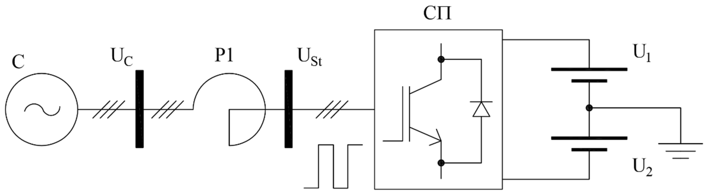
The STATCOM operating principle is based on fully controlled semiconductor valves. Generally, the STATCOM is connected to the AC grid through P1 reactors that are in charge of limiting the phase currents and diminishing higher harmonic currents, ensuring the electromagnetic compatibility between converter and grid.
2.1. Problem Formulation
Below,
Figure 1 shows a STATCOM with a control unit for communication of AC and DC networks.
The STATCOM diagram introduces the electrical functional relationship between the AC and DC voltage networks, where
and
are the network and converter voltages, respectively. DC voltage sources are (
U1,
U2). AC source and CП converter are connected to reactor P1. Whose resistance and inductive reactance values are given by
and
, respectively. The apparent power
S is determined with (1).
α is the phase angle between the static converter and substation bus voltages;
P and
Q are the active and reactive components of power.
where
XL is the inductive reactance (2) and
S the apparent power.
where
L is the reactor inductance value (3),
ω the angular frequency (50 Hz or 314 rad/s).
where
R is the reactor resistance value (4) and
is the reactor quality factor, that is 20 for 50 Hz frequency.
Operator assigns STATCOM’s nominal voltage and reactive power. Then, the inductance value of the three-phasic reactors group was calculated, taking into account previously assigned data.
Therefore, Equation (1) might be simplified as shown below in Equations (5)–(7), considering
α = 0.
When
α = 0, the equation of the real part disappears and power is entirely reactive. Under this condition and employing 41 MVA as STATCOM nominal power, it can be inferred that
voltage is provided by the network while converter voltage
is determined by STATCOM’s operation state, as we shall see below.
can be defined in terms of
through the multiplicity factor
.
For calculation purposes (8), it is assumed that multiplicity factor , since it can be regulated by the operator.
Table 1 contains the operator’s assigned nominal values, as well as three-phase reactors’ group resistance and reactance calculated values.
, , and , values were determined by Equations (2)–(4). Obtained data were entered into Matlab Simulink model so as to run the simulations.
A regulator is an element capable of providing valid and effective control solutions and responses to disturbances or problems in the real environment, in this case the electrical system [
47].
Table 2 shows the AC voltage regulator parameters applied. The equation that describes the behavior of the PI regulator is defined in [
48,
49].
is the proportional gain, is the integral gain and is a complex variable in the frequency domain.
Table 3 shows the parameters of the current controller. The proportional and integral constants of the PI regulators are the product of the transfer function [
16].
2.2. Method
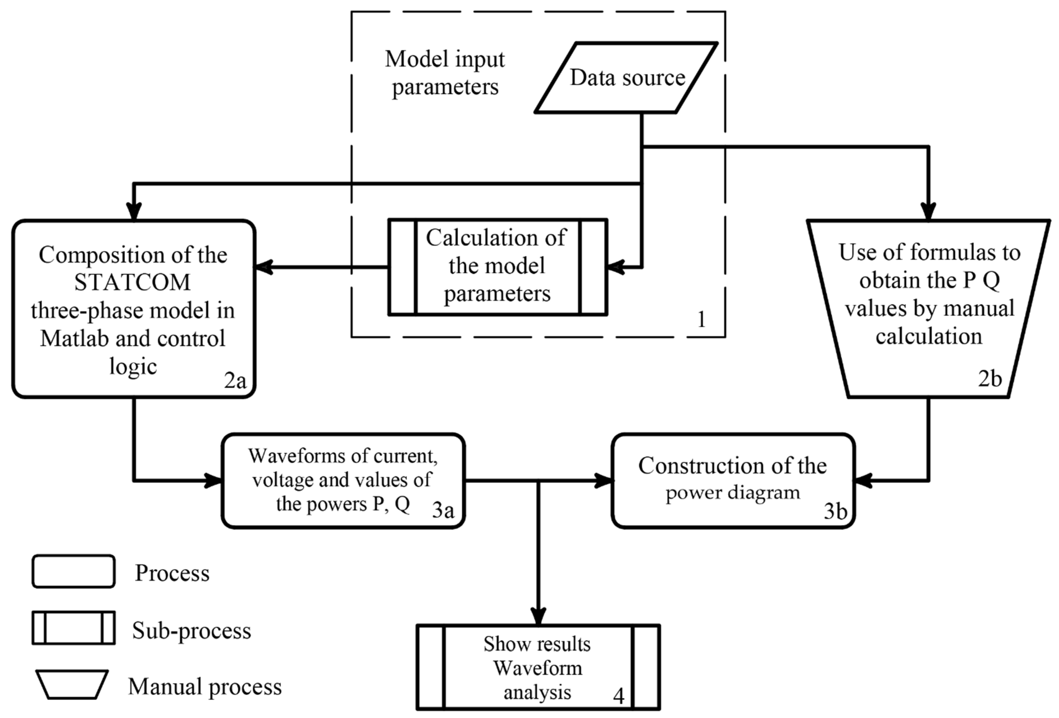
Figure 2 shows the proposed method flowchart. At point 1, the input data are described, and the model parameters are calculated.
At point 2a, STATCOM model composition is performed in Matlab Simulink; here, logic control is developed. In point 2b, the active and reactive power (P, Q) values are manually computed. In point 3a, the current and voltage waveforms are obtained, and as active and reactive power values are simulated in the software. At point 3b, the power diagram is constructed. Finally, in point 4, current and voltage waveforms analysis is done.
2.3. Operating Principle
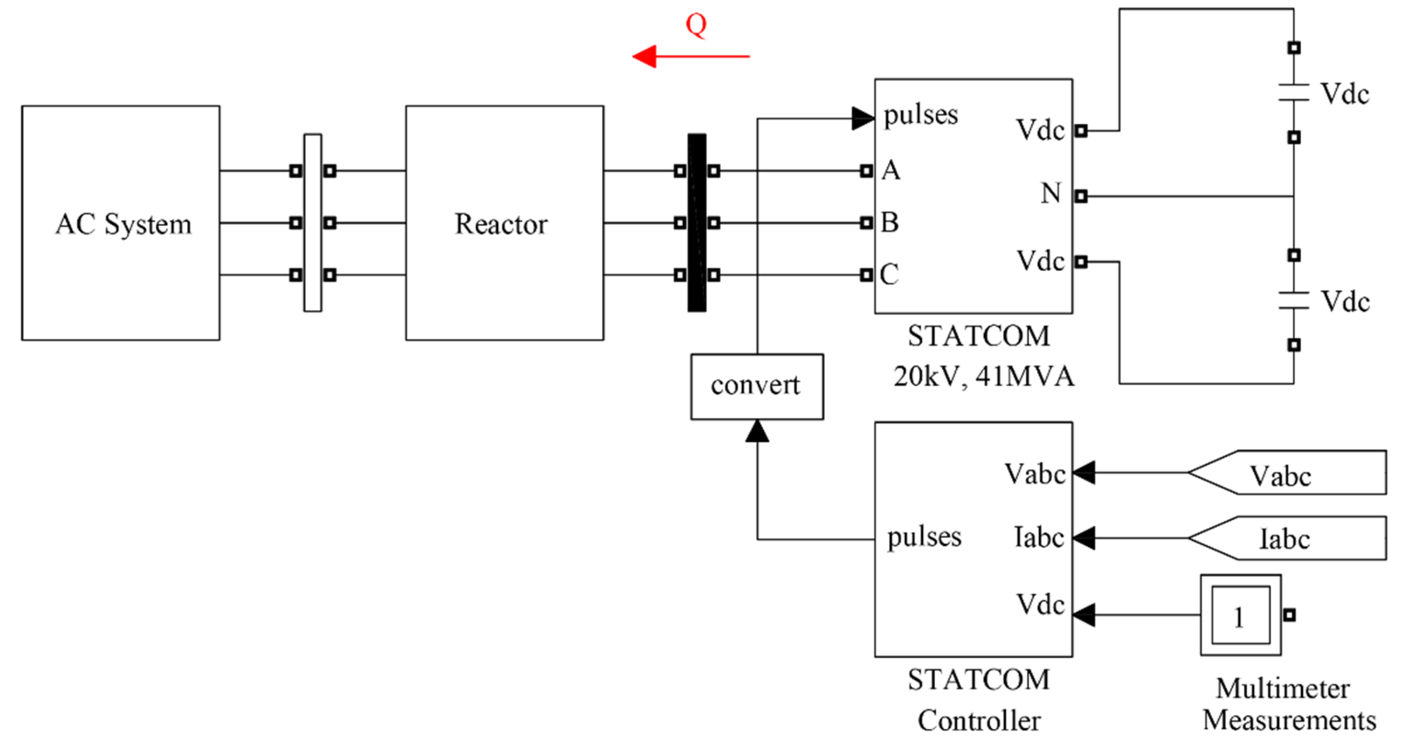
Static synchronous compensators (STATCOM) are widely used in electrical networks to compensate for reactive power. To date, these devices are mainly used in electrical substations.
Depicted in
Figure 3 are the STATCOM main elements: The control module, the DC voltage sources, and a measurement block are shown. The input voltage in DC is turned into AC by means of insulated gate bipolar transistors whose operation is managed by the control system whose generated pulses activate and deactivate transistors. In this way, a symmetrical three-phase voltage is obtained at the STATCOM output.
The inputs for voltage V
abc and current I
abc (
Figure 3) are the AC system measurements that enter the voltage regulator (outer loop).
Figure 4 depicts the control system elements. It basically contains voltage and current measuring block, a voltage regulator (outer loop), a current regulator (inner loop), a phase-locked loop PLL, a pulse generator, and the STATCOM.
The control system compares the measured voltage and the reference one , then the reactive component reference current is computed. This current gets into the current regulator and collate with measured current to ascertain Alpha value. Alpha is essentially the shift angle phase between the STATCOM output voltage and network supply voltage . Under stable conditions Alpha value is close to zero.
STATCOM system has the capability to work as a generator and consumer of active and reactive power, depending on the control phase angle between the STATCOM output and network voltages, as well as voltage modulus. The control device compares the measured voltage with reference voltage , as well as the angle formed between both phasors . When changing these parameters in the STATCOM, we can obtain four operating states: Reactive power consumer when = 0 and , active energy consumer when > 0 and , reactive power generator when = 0 and , and active power generator when > 0 and . The user determines the operating state just by varying these parameters on the equipment.
The phase-locked loop (PLL) is a phase synchronizer, this added to reference angle ωt allows to generate the pulses STATCOM needs. Finally, the DC regulator is an active power control for system internal losses.
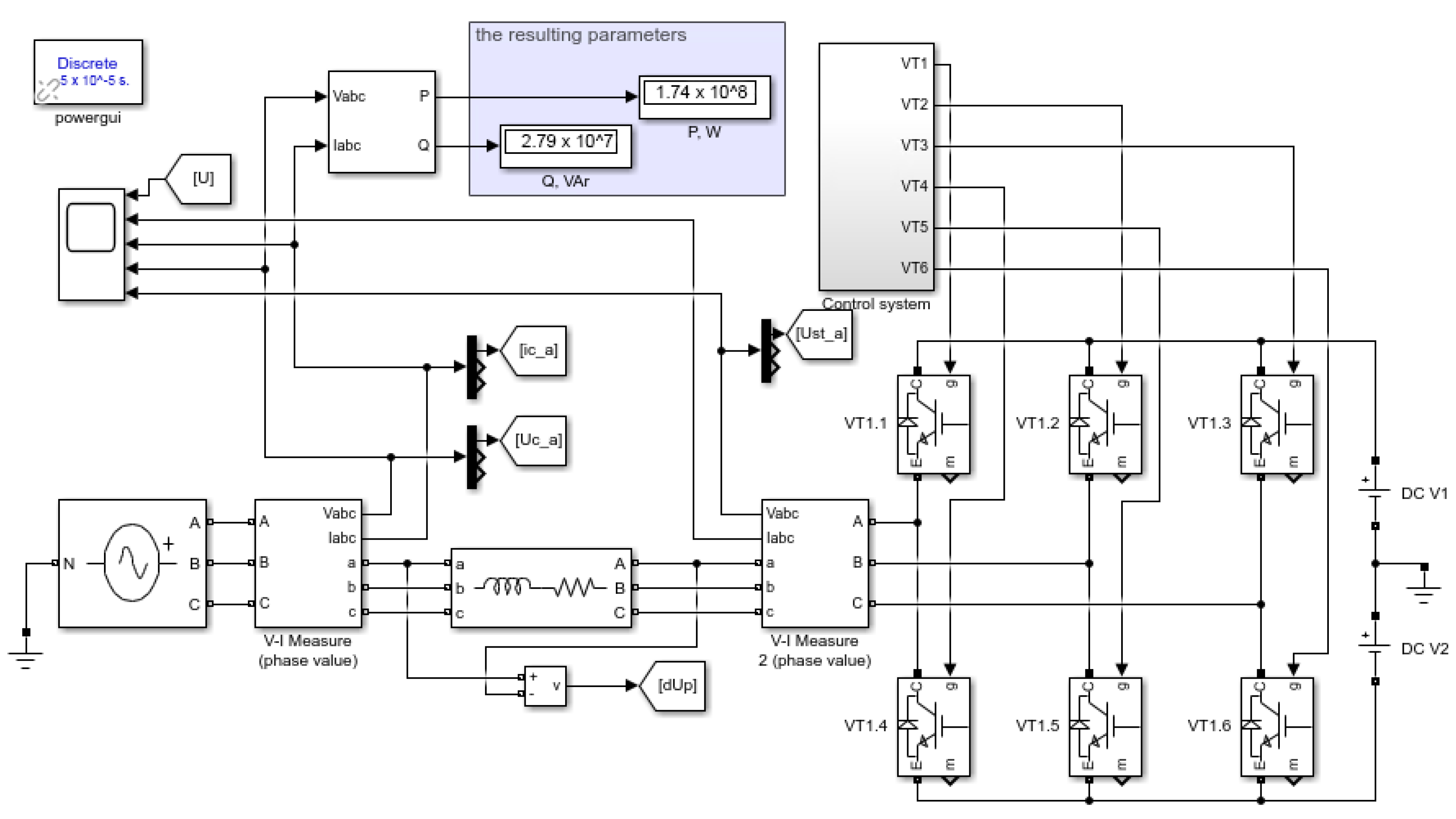
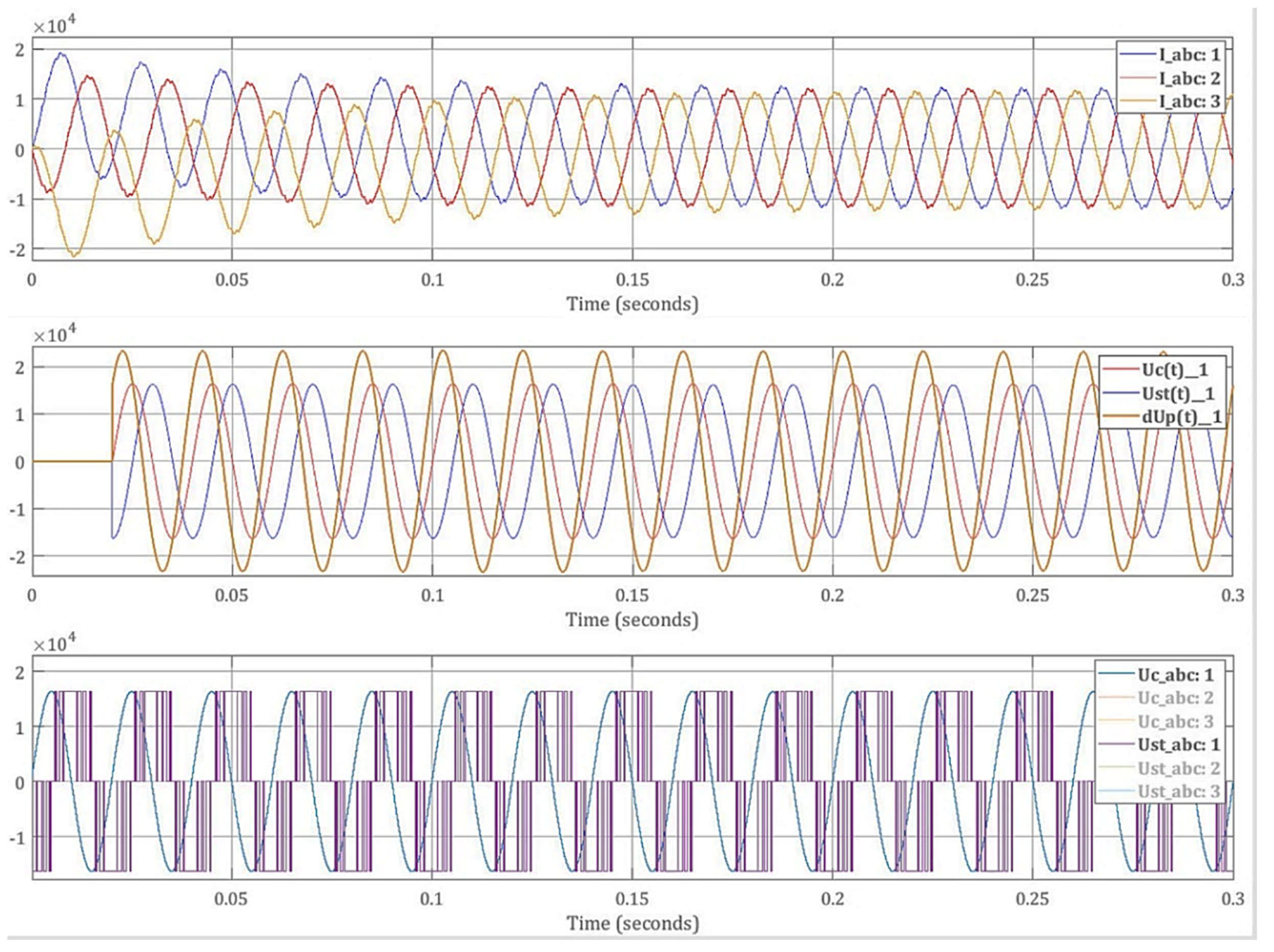
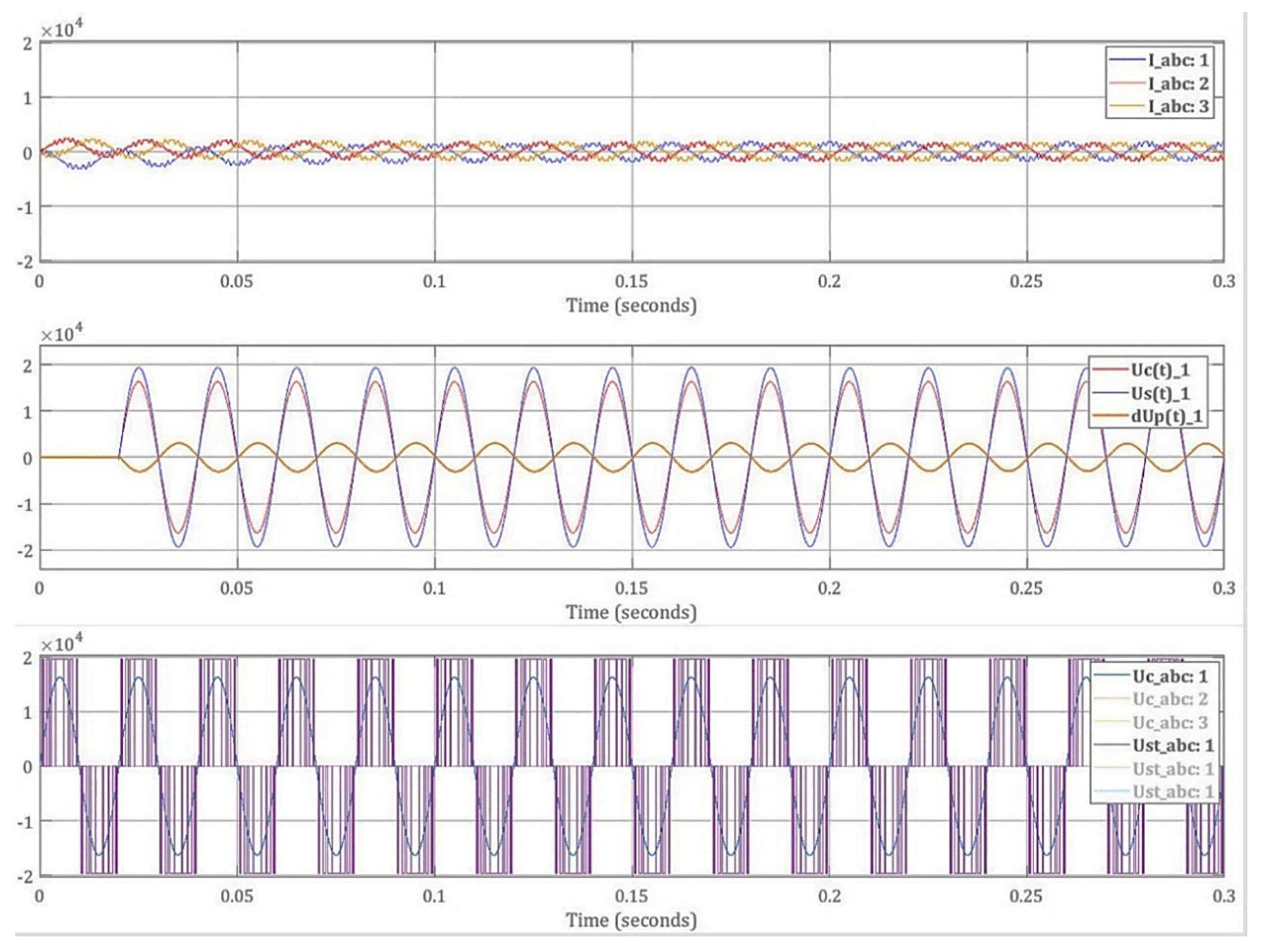
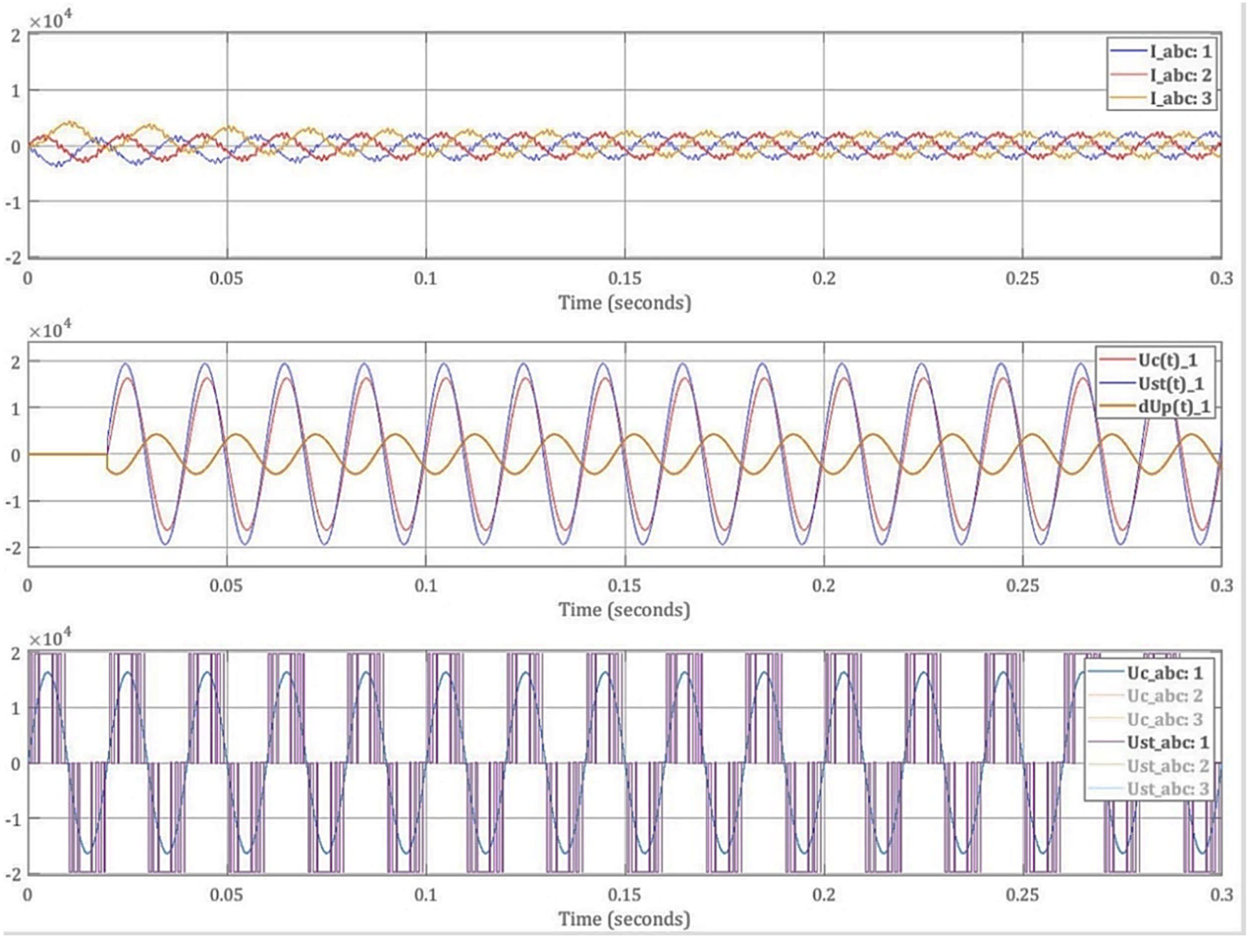
3. Results
In this section, the model developed in Matlab is shown. Here, the power and control part is represented. The result is a device that has the ability to supply reactive current within the voltage limits in the network. The STATCOM power diagram is shown in
Figure 5.
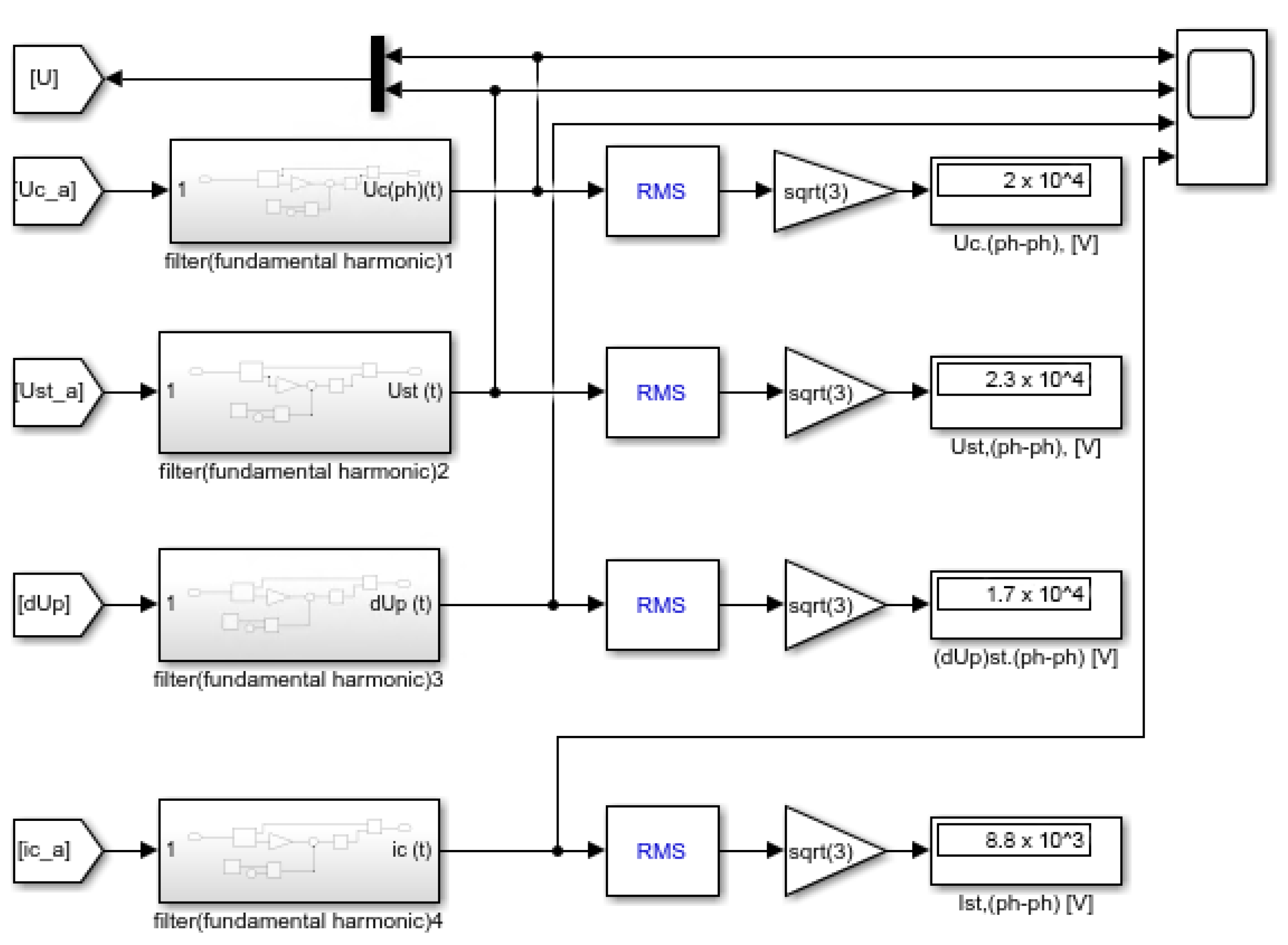
Figure 6 shows a block of measurements. A measurement block was designed in order to obtain the RMS values of the system and converter voltages, as well as the differential voltage between them, and flowing current through the system. For the effect, we use a Fourier block to come by signal fundamental harmonic; here, this block decomposes the input signal into modulus and phase angle.
The phase angle value after being conditioned goes through a sine function block and then the obtained value is multiplied by the modulus of the input signal. Finally, an RMS block is applied to determine the mean square value of the signal, which is the effective value that helps us to evaluate the device operation.
The power converter component incorporates the following elements: (1) Power system bus, modeled by a three-phase alternating sinusoidal voltage source; (2) voltage and current measuring instruments; (3) inductive reactance with low active resistance; (4) IGBT power transistors; and (5) constant voltage sources modeled by batteries.
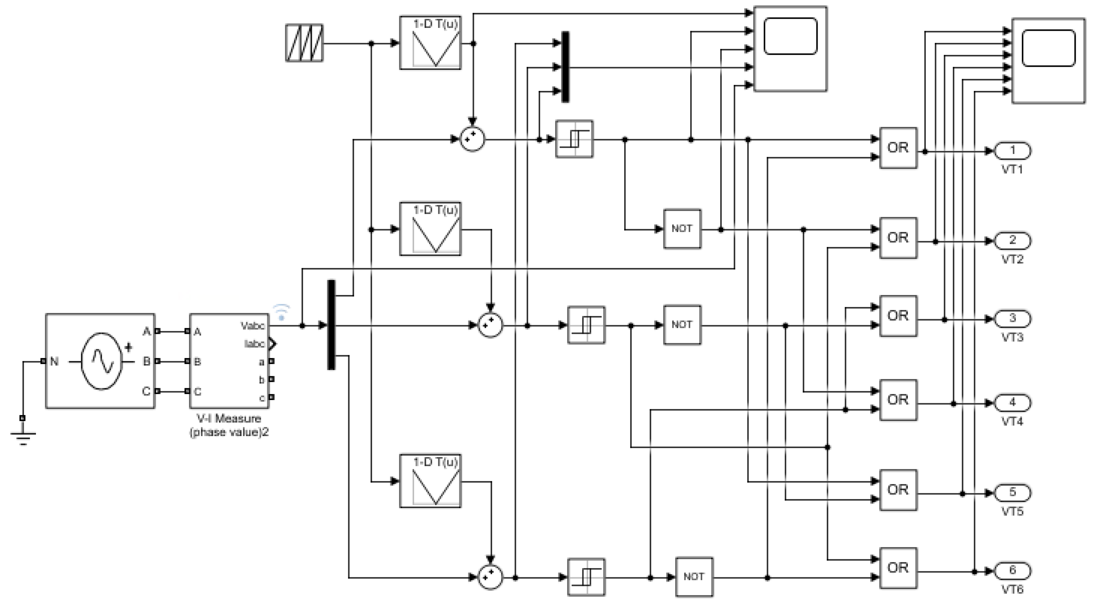
Figure 7 introduces the control system that has been designed, taking advantage of the pulse width modulation (PWM) principle. The output voltages are connected to the measuring instruments to assess the difference between the network and the converter voltage angles. The signals are arranged by adding to the carrier signals (saw tooth signal) and the reference signals (sinusoidal voltage); to reach this, a switching relay was used when the input signal passes through zero.
Table 4 shows the active and reactive power values obtained by means of Matlab Simulink, as well as the manually calculated ones by using Formulas (5) and (6). These data directly depend on the voltage multiplicity factor and the lag angle between
and
. Both values are adjusted according to operating requirements.
where
P is the active power manually calculated data.
where
Q is the reactive power manually calculated data.
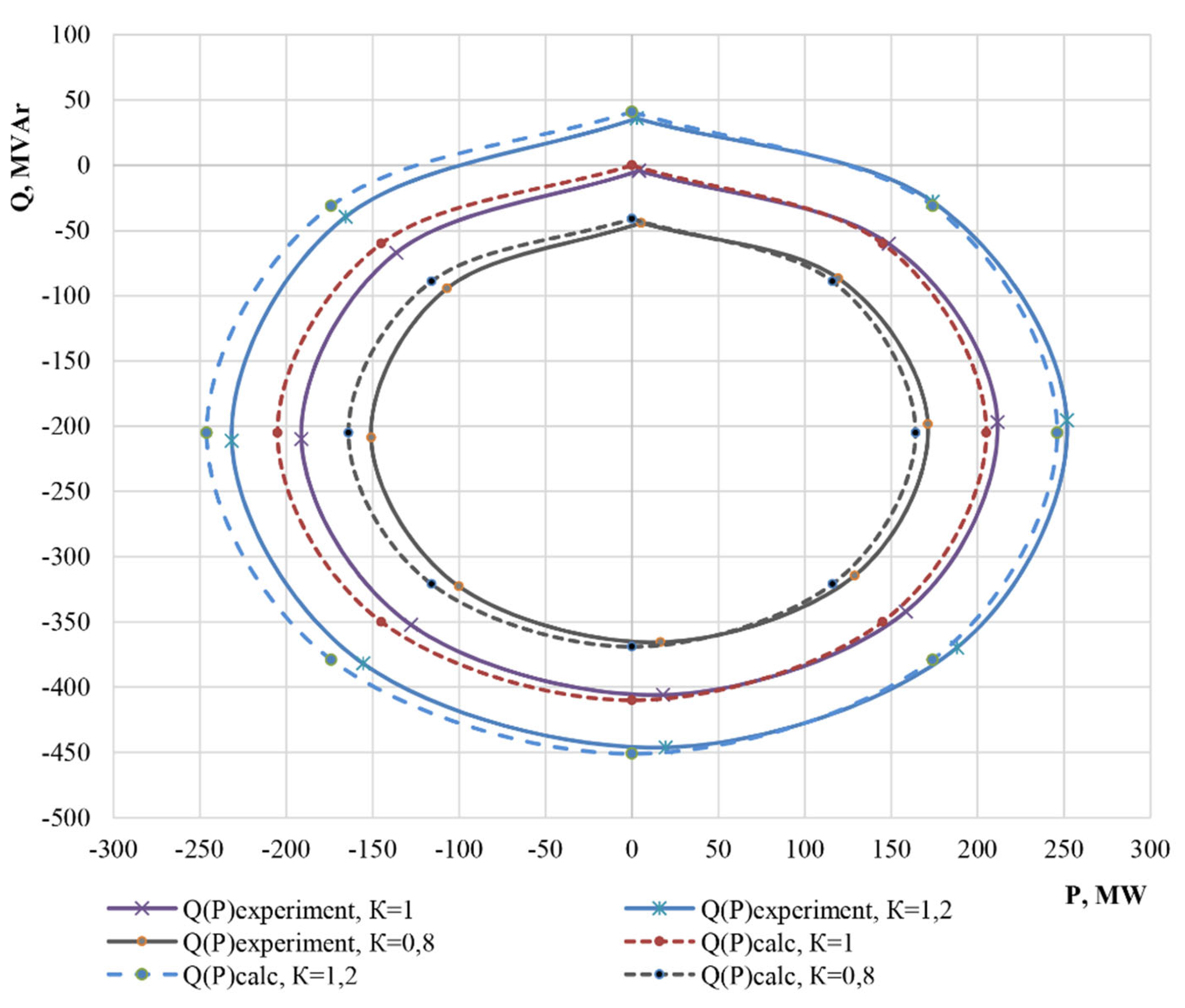
By analyzing the circular power chart (
Figure 8), we can infer that STATCOM can be used for both consumption and generation of active and reactive power. Furthermore, static voltage converters are already used for such purposes in wind and solar power plants to connect to AC networks.
4. Discussion
The STATCOM presented in this research is a VSC-based device, where the reactive power generated at the terminals depends on the amplitude of the voltage source. If the VSC voltage is higher than the AC voltage at the connection point, the STATCOM generates a reactive current [
50]. On the other hand, its response time is shorter than that of an SVC, mainly due to the fast-switching times provided by IGBTs [
51]. The proposed model has the capability to cope with voltage drops originating from switching electrical loads or when the power supply is reduced due to intermittency of renewable energy sources.
In addition to that for large powers, they are usually integrated with battery energy storage systems (BESS) [
52] or super capacitor energy storage system (SCESS) [
53], being able to stabilize phase voltages. However, this proposal is limited because big systems would be needed to perform the compensation, therefore it is recommended to investigate a methodology for sizing specific cases.
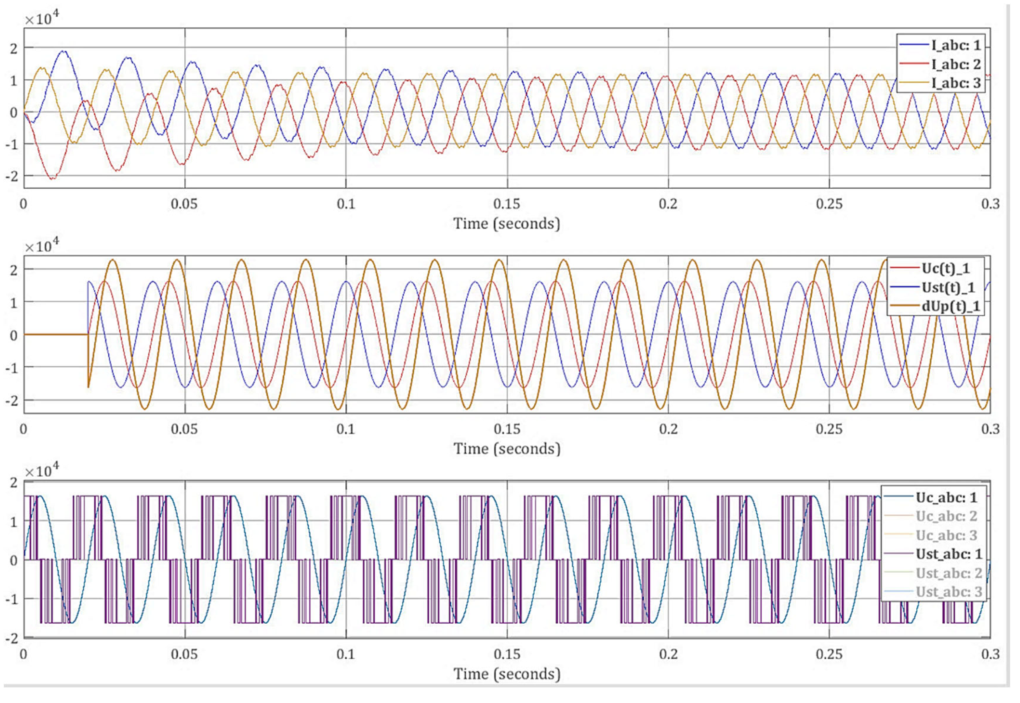
Despite the level of simulation, it was verified that the converter injects the necessary reactive power to the grid, and this is stable, since when making changes in the transfer phase angle and voltage modulus, the system responds appropriately. In addition, thanks to the simulations, it was demonstrated that the inductance and capacitance values of the converter were properly calculated since they maintain the voltage values within the allowed limits.
STATCOMs can handle high power levels. The authors of [
54,
55,
56] talked about 100 MVA fully operational devices in Korea and USA, whose operating tests have been successful. Additionally, in [
57], it is mentioned that a shunt connected STATCOM that operates as a VARs capacitive or inductive compensator can be controlled independently of the network voltage.
These systems have among their main benefits the reduction of harmonics in the voltage lines, something that has already been proven as indicated by [
31,
32,
33]. This contributes to their association with simulated renewable energy sources, whether they are photovoltaic [
34,
42,
43], solar [
39], or wind [
35,
36,
37,
38,
41], and even if their application is in electrified railways [
44]. All these proposals present favorable results depending on the application and case study developed, both in the treatment of total harmonic distortion (THD) and in the conservation of synchronism of systems involving renewable energies. This means that it is not easy to make a comparison of their results, since the points of view taken in the studies are diverse. However, they have served as a bibliographic basis and guide for this research, as well as a confirmation of their efficient operation in simulations in the field of clean energies.
5. Conclusions
In this paper, the three-phase static voltage converter operation modes was analyzed, and the design-appropriate performance under different operating conditions was demonstrated. It has been shown that STATCOM improves power quality by reducing power oscillations and compensating for reactive power, as well as regulating and stabilizing voltage.
In the proposed design, a 41 MVA was assigned as the converter nominal power value. However, in a real application, these data are provided by system nominal load, according to the case study.
The three-phase static converter control principle is rooted in pulse width modulation, where the control system grants the obtainment of a balanced three-phase voltage as the converter output from common DC sources.
An important characteristic that allows STATCOM to generate/consume active and reactive power is voltage modulus and angle independent regulation. Consumed and generated capacities were calculated and simulated, and the circular power chart was depicted.
Through the circular power chart, it could be inferred that as the converter voltage increases, the STATCOM consumed/generated power also does. Therefore, as converter voltage amplitude increases, so does power consumed or generated. This means power can be adjusted by modifying converter voltage values. Furthermore, regulation is done by changing the transistor control system´s sinusoidal source phase.
As the phase angle approaches 90°, the converter generates a maximum active power value; however, sustained active energy generation/consumption requires an energy storage system installed on the rectified voltage side.
In contrast, theoretically obtained and manually calculated data show that when the phase angle approaches 0°, we will get a maximum reactive energy generation.
The STATCOM total power depends directly on network supply voltage, the STATCOM output voltage, and the phase angle, inversely with the coupling impedance value. For nominal operation with 1.2 as the multiplicity factor, a 41 MVAr STATCOM that operates at 20 kV is able to generate 251.6 MW or 35.95 MVAr, or consume −231.5 MW or −446.2 MVAR, as to limit values.
Finally, according to the results, we can conclude that through STATCOM, purely active or reactive power consumption or generation can ideally be achieved.
Author Contributions
Conceptualization, B.S.K. and M.A.-C.; methodology, M.A.-C., and B.S.K.; software, B.S.K., M.A.-C., and J.V.-A.; validation, M.A.-C., and B.S.K.; formal analysis, M.A.-C., and B.S.K.; investigation, M.A.-C., and B.S.K.; resources, M.A.-C., B.S.K., J.V.-A., and J.B.; writing—original draft preparation, M.A.-C. and B.S.K.; writing—review and editing, M.A.-C., B.S.K., J.V.-A., and J.B.; visualization, M.A.-C. and B.S.K. All authors have read and agreed to the published version of the manuscript.
Funding
This research was funded by Universidad Tecnológica Indoamérica.
Institutional Review Board Statement
Not applicable.
Informed Consent Statement
Not applicable.
Data Availability Statement
Not applicable.
Acknowledgments
Cristian Gallardo, Jorge Peralta, Universidad Tecnológica Indoamérica and Secretaría de Educación Superior, Ciencia, Tecnología e Innovación SENESCYT.
Conflicts of Interest
The authors declare no conflict of interest.
References
- Sadovskaia, K.; Bogdanov, D.; Honkapuro, S.; Breyer, C. Power transmission and distribution losses—A model based on available empirical data and future trends for all countries globally. Int. J. Electr. Power Energy Syst. 2019, 107, 98–109. [Google Scholar] [CrossRef]
- Tu, G.; Li, Y.; Xiang, J. Analysis, control and optimal placement of static synchronous compensator with/without battery energy storage. Energies 2019, 12, 4715. [Google Scholar] [CrossRef]
- Surana, K.; Jordaan, S.M. The climate mitigation opportunity behind global power transmission and distribution. Nat. Clim. Chang. 2019, 9, 660–665. [Google Scholar] [CrossRef]
- Abbas, A.O.; Chowdhury, B.H. Using customer-side resources for market-based transmission and distribution level grid services—A review. Int. J. Electr. Power Energy Syst. 2021, 125, 106480. [Google Scholar] [CrossRef]
- Arya, Y.; Kumar, N.; Gupta, S.K. Optimal automatic generation control of two-area power systems with energy storage units under deregulated environment. J. Renew. Sustain. Energy 2017, 9, 064105. [Google Scholar] [CrossRef]
- Gomis-Bellmunt, O.; Sau-Bassols, J.; Prieto-Araujo, E.; Cheah-Mane, M. Flexible Converters for Meshed HVDC Grids: From Flexible AC Transmission Systems (FACTS) to Flexible DC Grids. IEEE Trans. Power Deliv. 2020, 35, 2–15. [Google Scholar] [CrossRef]
- Kotsampopoulos, P.; Georgilakis, P.; Lagos, D.T.; Kleftakis, V.; Hatziargyriou, N. Facts providing grid services: Applications and testing. Energies 2019, 12, 2554. [Google Scholar] [CrossRef]
- Safari, A.; Bagheri, M.; Shayeghi, H. Optimal setting and placement of FACTS devices using strength Pareto multi-objective evolutionary algorithm. J. Cent. South Univ. 2017, 24, 829–839. [Google Scholar] [CrossRef]
- Oukennou, A.; Sandali, A.; Elmoumen, S. Coordinated placement and setting of FACTS in electrical network based on Kalai-Smorodinsky bargaining solution and voltage deviation index. Int. J. Electr. Comput. Eng. 2018, 8, 4079–4088. [Google Scholar] [CrossRef]
- Raj, S.; Bhattacharyya, B. Optimal placement of TCSC and SVC for reactive power planning using Whale optimization algorithm. Swarm Evol. Comput. 2018, 40, 131–143. [Google Scholar] [CrossRef]
- Sirjani, R.; Rezaee Jordehi, A. Optimal placement and sizing of distribution static compensator (D-STATCOM) in electric distribution networks: A review. Renew. Sustain. Energy Rev. 2017, 77, 688–694. [Google Scholar] [CrossRef]
- Reddy, S.S. Optimal placement of FACTS controllers for congestion management in the deregulated power system. Int. J. Electr. Comput. Eng. 2018, 8, 1336–1344. [Google Scholar] [CrossRef]
- AL Ahmad, A.; Sirjani, R. Optimal placement and sizing of multi-type FACTS devices in power systems using metaheuristic optimisation techniques: An updated review. Ain Shams Eng. J. 2019, 11, 611–628. [Google Scholar] [CrossRef]
- Sumi, Y.; Harumoto, Y.; Hasegawa, T.; Yano, M.; Ikeda, K.; Matsuura, T. New static var control using force-commutated inverters. IEEE Trans. Power Appar. Syst. 1981, PAS-100, 4216–4224. [Google Scholar] [CrossRef]
- Davidson, C.; Oliveira, M. Technical Description of Static Compensators (STATCOM). In Flexible AC Transmission Systems; Springer: Cham, Switzerland, 2019; ISBN 9783030353865. [Google Scholar]
- Farhad, S.; Sumedha, R.; Arindam, G. Static Compensators (STATCOMs) in Power Systems; Power Systems; Springer: Singapore, 2015; ISBN 9789812872807. [Google Scholar]
- Perelmuter, V. Electrotechnical Systems: Simulation with Simulink®and SimPowerSystemsTM; CRC Press: Boca Raton, FL, USA, 2020; ISBN 9781466514034. [Google Scholar]
- Xu, C.; Chen, J.; Dai, K. Carrier-Phase-Shifted Rotation Pulse-Width-Modulation Scheme for Dynamic Active Power Balance of Modules in Cascaded H-Bridge STATCOMs. Energies 2020, 13, 1052. [Google Scholar] [CrossRef]
- Acha, E.; Agelidis, V.; Anaya-Lara, O.; Miller, T.J.E. Power Electronic Control in Electrical Systems; Electronics & Electrical; Elsevier Science: Oxford, UK, 2002; ISBN 9780750651264. [Google Scholar]
- Li, Y.; Humayun, M. Analysis of Cross-Connected Half-Bridges Multilevel Inverter for STATCOM Application. Electronics 2020, 9, 1898. [Google Scholar] [CrossRef]
- Muyeen, S.M.; Tamura, J.; Murata, T. (Eds.) Statcom. In Stability Augmentation of a Grid-Connected Wind Farm; Springer: London, UK, 2008; pp. 105–136. ISBN 978-1-84800-316-3. [Google Scholar]
- Diab, A.; Ebraheem, T.; Aljendy, R.; Sultan, H.; Ali, Z. Optimal Design and Control of MMC STATCOM for Improving Power Quality Indicators. Appl. Sci. 2020, 10, 2490. [Google Scholar] [CrossRef]
- Tripathi, S.M.; Barnawal, P.J. Design and Control of a STATCOM for Non-Linear Load Compensation: A Simple Approach. Electr. Control Commun. Eng. 2018, 14, 172–184. [Google Scholar] [CrossRef]
- Hu, P.; Guerrero, J.M.; He, Z. Design and analysis of a transformerless STATCOM based on hybrid cascaded multilevel converter. Int. J. Electr. Power Energy Syst. 2019, 104, 694–704. [Google Scholar] [CrossRef]
- Qatamin, A.; Etawi, A.; Safasfeh, G.; Ajarmah, N.; Al-Jufout, S.; Drous, I.; Wang, C.; Soliman, A.H. SVC versus STATCOM for improving power system loadability: A case study. In Proceedings of the 2017 8th International Renewable Energy Congress (IREC), Amman, Jordan, 21–23 March 2017. [Google Scholar]
- Hemeida, M.G.; Rezk, H.; Hamada, M.M. A comprehensive comparison of STATCOM versus SVC-based fuzzy controller for stability improvement of wind farm connected to multi-machine power system. Electr. Eng. 2018, 100, 935–951. [Google Scholar] [CrossRef]
- Lei, Y.; Li, T.; Tang, Q.; Wang, Y.; Yuan, C.; Yang, X.; Liu, Y. Comparison of UPFC, SVC and STATCOM in Improving Commutation Failure Immunity of LCC-HVDC Systems. IEEE Access 2020, 8, 135298–135307. [Google Scholar] [CrossRef]
- Cherkaoui, N.; Haidi, T.; Belfqih, A.; El Mariami, F.; Boukherouaa, J. A Comparison Study of Reactive Power Control Strategies in Wind Farms with SVC and STATCOM. Int. J. Electr. Comput. Eng. 2018, 8, 4836. [Google Scholar] [CrossRef]
- Qi, J.; Zhao, W.; Bian, X. Comparative Study of SVC and STATCOM Reactive Power Compensation for Prosumer Microgrids with DFIG-Based Wind Farm Integration. IEEE Access 2020, 8, 209878–209885. [Google Scholar] [CrossRef]
- Li, L.; Zhang, X. Study on STATCOM principle and control strategy under short circuit fault. In Proceedings of the 2017 IEEE International Conference on Mechatronics and Automation (ICMA), Takamatsu, Japan, 6–9 August 2017; pp. 1187–1191. [Google Scholar]
- Kontos, E.; Tsolaridis, G.; Teodorescu, R.; Bauer, P. High Order Voltage and Current Harmonic Mitigation Using the Modular Multilevel Converter STATCOM. IEEE Access 2017, 5, 16684–16692. [Google Scholar] [CrossRef]
- Sajadi, R.; Iman-Eini, H.; Bakhshizadeh, M.K.; Neyshabouri, Y.; Farhangi, S. Selective harmonic elimination technique with control of capacitive DC-link voltages in an asymmetric cascaded H-Bridge Inverter for STATCOM Application. IEEE Trans. Ind. Electron. 2018, 65, 8788–8796. [Google Scholar] [CrossRef]
- Soodi, H.A.; Vural, A.M. Design, Optimization and Experimental Verification of a Low Cost Two-Microcontroller Based Single-Phase STATCOM. IETE J. Res. 2021. [Google Scholar] [CrossRef]
- Tareen, W.U.K.; Aamir, M.; Mekhilef, S.; Nakaoka, M.; Seyedmahmoudian, M.; Horan, B.; Memon, M.A.; Baig, N.A. Mitigation of power quality issues due to high penetration of renewable energy sources in electric grid systems using three-phase APF/STATCOM technologies: A review. Energies 2018, 11, 1491. [Google Scholar] [CrossRef]
- Guchhait, P.K.; Banerjee, A. Stability enhancement of wind energy integrated hybrid system with the help of static synchronous compensator and symbiosis organisms search algorithm. Prot. Control Mod. Power Syst. 2020, 5, 11. [Google Scholar] [CrossRef]
- Gandhar, A.; Gupta, S.; Gandhar, S. Improvement of transient stability margin in RES Based Power Systems Using STATCOM. Asian J. Water Environ. Pollut. 2018, 15, 1–4. [Google Scholar] [CrossRef]
- Wang, T.; Song, G.; Hussain, K.S.T. Three-Phase Adaptive Auto-Reclosing for Single Outgoing Line of Wind Farm Based on Active Detection from STATCOM. IEEE Trans. Power Deliv. 2020, 35, 1918–1927. [Google Scholar] [CrossRef]
- Singh, B.; Verma, A.; Giri, V.K. Power Quality Improvement of Grid Connected PV System. In Proceedings of the 2020 IEEE India Council International Subsections Conference (INDISCON), Visakhapatnam, India, 3–4 October 2020; pp. 188–194. [Google Scholar]
- Chavan, P.M.; Chavan, G.P. Interfacing of hybrid power system to grid using statcom & power quality improvement. In Proceedings of the IEEE International Conference on Information, Communication, Instrumentation and Control (ICICIC), Indore, India, 17–19 August 2017; pp. 1–5. [Google Scholar]
- Zhang, Y.; Chen, X.; Sun, J. Impedance modeling and control of STATCOM for damping renewable energy system resonance. In Proceedings of the 2017 IEEE Energy Conversion Congress and Exposition (ECCE), Cincinnati, OH, USA, 1–5 October 2017; pp. 3295–3302. [Google Scholar]
- Fayek, A.; Salimullah, S.M.; Hossain, M.S.; Hossain, R.; Shakib, M.S.H.; Anik, A.I.; Khan, M.H. STATCOM and PID controller based stability enhancement of a grid connected wind farm. In Proceedings of the International Conference on Energy and Power Engineering: Power for Progress (ICEPE), Dhaka, Bangladesh, 14–16 March 2019. [Google Scholar]
- Popavath, L.; Kaliannan, P. Photovoltaic-STATCOM with Low Voltage Ride through Strategy and Power Quality Enhancement in a Grid Integrated Wind-PV System. Electronics 2018, 7, 51. [Google Scholar] [CrossRef]
- Aiswarya, D.; Ilango, K.; Nair, M.G. A comparative performance analysis of PV grid interface STATCOM control algorithms. In Proceedings of the 2017 Innovations in Power and Advanced Computing Technologies (i-PACT), Vellore, India, 21–22 April 2017; pp. 1–7. [Google Scholar]
- Rodrigues, P.; Morais, V.A.; Martins, A.; Carvalho, A. STATCOM Simulation Models for Analysis of Electrified Railways. In Proceedings of the IECON 2019—45th Annual Conference of the IEEE Industrial Electronics Society, Lisbon, Portugal, 14–17 October 2019; pp. 2257–2262. [Google Scholar]
- Sreedharan, S.; Joseph, T.; Joseph, S.; Chandran, C.V.; Vishnu, J.; Das, V. Power system loading margin enhancement by optimal STATCOM integration—A case study. Comput. Electr. Eng. 2020, 81, 106521. [Google Scholar] [CrossRef]
- Xie, X.; Zhong, J.; Sun, Y.; Wang, J.; Wei, C. Online Optimal Power Control of an Offshore Oil-Platform Power System. Technol. Econ. Smart Grids Sustain. Energy 2018, 3, 18. [Google Scholar] [CrossRef][Green Version]
- Li, Y.; Feng, W.; Zhu, X.; Tan, K.C.; Guan, X.; Ang, K.H. PIDeasy and automated generation of optimal PID controllers. In Proceedings of the 3rd Asia-Pacific Conference on Control and Measurement, Dunhuang, China, 31 August–4 September 1998. [Google Scholar]
- Quevedo, J.; Escobet, T. Digital Control 2000: Past, Present and Future of PID Control; Elsevier Science Inc.: Terrasa, Spain, 2000; ISBN 9780080436241. [Google Scholar]
- Xu, Y.; Li, F. Adaptive PI control of STATCOM for voltage regulation. IEEE Trans. Power Deliv. 2014, 29, 1002–1011. [Google Scholar] [CrossRef]
- Al-Nimma, D.A.; Al-Hafid, M.S.M.; Mohamed, S.E. Voltage profile improvements of Mosul city ring system by STATCOM reactive power control. In Proceedings of the International Aegean Conference on Electrical Machines and Power Electronics and Electromotion, Joint Conference, Istanbul, Turkey, 8–10 September 2011; pp. 525–530. [Google Scholar]
- Hingorani, N.G.; Gyugyi, L. Static Shunt Compensators: SVC and STATCOM. In Understanding FACTS; Wiley-IEEE Press: Hoboken, NJ, USA, 1999; pp. 135–207. [Google Scholar]
- Aleem, S.A.; Hussain, S.M.S.; Ustun, T.S. A Review of Strategies to Increase PV Penetration Level in Smart Grids. Energies 2020, 13, 636. [Google Scholar] [CrossRef]
- Afzal, M.M.; Khan, M.A.; Hassan, M.A.S.; Wadood, A.; Uddin, W.; Hussain, S.; Rhee, S.B. A Comparative Study of Supercapacitor-Based STATCOM in a Grid-Connected Photovoltaic System for Regulating Power Quality Issues. Sustainability 2020, 12, 6781. [Google Scholar] [CrossRef]
- Shperling, B.; Sun, J.; Bhattacharya, S. Power flow control on 345 kV lines with the 200 MVA convertible static compensator. In Proceedings of the 2005 IEEE Russia Power Tech, St. Petersburg, Russia, 27–30 June 2005; pp. 1–7. [Google Scholar]
- Yoon, J.; Kim, S.; Kim, Y.; Lee, K.; Lee, C. The analysis of STATCOM and SVC cooperation effect. In Proceedings of the 2009 Transmission Distribution Conference Exposition: Asia and Pacific, Seoul, Korea, 26–30 October 2009; pp. 1–5. [Google Scholar]
- Schauder, C.; Gernhardt, M.; Stacey, E.; Lemak, T.; Gyugyi, L.; Cease, T.W.; Edris, A. Operation of /spl plusmn/100 MVAr TVA STATCON. IEEE Trans. Power Deliv. 1997, 12, 1805–1811. [Google Scholar] [CrossRef]
- Barrios-Martínez, E.; Ángeles-Camacho, C. Technical comparison of FACTS controllers in parallel connection. J. Appl. Res. Technol. 2017, 15, 36–44. [Google Scholar] [CrossRef]
| Publisher’s Note: MDPI stays neutral with regard to jurisdictional claims in published maps and institutional affiliations. |
© 2021 by the authors. Licensee MDPI, Basel, Switzerland. This article is an open access article distributed under the terms and conditions of the Creative Commons Attribution (CC BY) license (https://creativecommons.org/licenses/by/4.0/).


