Article

A New Decentralized Control Strategy of Microgrids in the Internet of Energy Paradigm

1
Department of Electrical Engineering, University of Basrah, Basrah 61001, Iraq
2
Department of Electrical Engineering, Mansoura University, Mansoura 35516, Egypt
3
Oregon Renewable Energy Center (OREC), Department of Electrical Engineering and Renewable Energy, Oregon Institute of Technology, Klamath Falls, OR 97601, USA
4
Center for Research on Microgrids (CROM), Department of Energy Technology, Aalborg University, 9220 Aalborg, Denmark
*
Authors to whom correspondence should be addressed.
Energies 2021, 14(8), 2183; https://doi.org/10.3390/en14082183
Submission received: 9 February 2021 / Revised: 9 March 2021 / Accepted: 16 March 2021 / Published: 14 April 2021

Abstract

:
The Energy Internet paradigm is the evolution of the Internet of Things concept in the power system. Microgrids (MGs), as the essential element in an Energy Internet, are expected to be controlled in a corporative and flexible manner. This paper proposes a novel decentralized robust control strategy for multi-agent systems (MASs) governed MGs in future Energy Internet. The proposed controller is based on a consensus algorithm applied with the connected distributed generators (DGs) in the MGs in the energy internet paradigm. The proposed controller’s objectives are the frequency/voltage regulation and proportional reactive/active power-sharing for the hybrid DGs connected MGs. A proposed two-level communication system is implemented to explain the data exchange between the MG system and the cloud server. The local communication level utilizes the transmission control protocol (TCP)/ internet protocol (IP) and the message queuing telemetry transport (MQTT) is used as the protocol for the global communication level. The proposed control strategy has been verified using a hypothetical hybrid DGs connected MG such as photovoltaic or wind turbines in MATLAB Simulink environment. Several scenarios based on the system load types are implemented using residential buildings and small commercial outlets. The simulation results have verified the feasibility and effectiveness of the introduced strategy for the MGs’ various operating conditions.

1. Introduction

Many studies have reported the use of a microgrid. A microgrid usually consists of distributed generators (DGs), loads and energy storage systems. The DGs are generally connected to the microgrids with powered electronic devices and can be regulated using hierarchical controllers for fulfilling different objectives like frequency regulation and active power-sharing [1].
Internet of Things (IoT) refers to a paradigm, which connects various digital, real and virtual devices (via information networks) to smart environments. It is applicable in many domains such as transportation, energy and cities. Energy Internet is regarded as a revolutionary network of smart grids. It is seen to be a general IoT application in the energy and power sectors. The Energy Internet consists of different techniques and components, which are summarized into three categories, i.e., (i) power systems, (ii) communication systems and (iii) control algorithms. In one study, the researchers stated that the Energy Internet’s cross-disciplinary nature had presented several opportunities and challenges, which have to be investigated further and validated [2].
It was noted that the MGs act as primary building blocks in an Energy Internet since they can be operated in the grid-connected and islanded modes [3]. A droop-based primary control can be used for autonomous power-sharing among all connected DGs. The islanded MGs’ secondary control feature allows voltage/frequency restoration while maintaining precise power-sharing among the connected DGs [4]. Furthermore, the tertiary control helps in the optimal operation of the MGs [5,6]. In the hierarchical control scheme, tertiary control helps determine the optimal dispatch values, which are based on renewable and load forecasting. Regarding the dispatch intervals, both the primary and the secondary controls are operated for sharing the actual power deviation taking place from the dispatch values. The distributed consensus algorithm-based secondary control and the distributed optimization algorithm-based tertiary controls have garnered a lot of research attention owing to their increased flexibility and resilience compared to the centralized control [7,8]. Furthermore, the implementation of a distributed algorithm is dependent on Multi-Agent System (MAS), wherein multiple subsystems/agents interact with one another with the help of sparse communication networks [9].
To the best of the authors’ knowledge, achieving reactive power, active power-sharing and voltage and frequency regulation with preserved local information privacy is still an open question. To this end, this letter presents a distributed privacy-preserving consensus (PPC)-based method to achieve reactive power, active power-sharing and voltage and frequency regulation in microgrids. First, the original control problem is transformed into an equivalent active power reference generation problem which can be solved by obtaining the global active power utilization level. Further, a distributed PPC algorithm is proposed to acquire this global variable. In addition, this paper targets to provide potential solutions for the following three scenarios: (i) The distributed controllers may neither be located at the same location as DGs nor have a proprietary communication network. The remote control of MGs via the Internet, taking communication latency into consideration, is required. (ii) For MGs governed by MASs, each agent or sub-MAS can be practically owned by different stakeholders who could cooperate or work independently. A flexible control framework with plug-and-play capability is needed. (iii) With the advancements in IoT and renewable technology, the number of controllable units in MGs is dramatically increasing. Any distributed control framework’s scalability to withstand increasing numbers of DGs is a problem worthy of exploration.
The rest of this paper is organized as follows. Section 1.1 introduces a description of the related works and Section 1.2. Paper contribution, Section 2 presents the proposed system description, Section 3 introduces the proposed hierarchical control, Section 3.1 presents problem formulation. Section 3.2 introduces the primary control of inverter-based distributed generators, Section 3.3 offers MASs communication networks, Section 3.4 presents the proposed secondary distributed controller, Section 4 introduces the proposed Internet of the energy communication platform, Section 5 Result analysis and discussion proposed method, Section 6 presents the access of internet web page. Finally, Section 7 concludes the paper.

1.1. Related Works

Traditionally, active power-sharing is achieved by droop control. A centralized controller is then utilized to compensate for frequency deviations caused by droop control [10,11]. However, the centralized control structure lacks flexibility and is susceptible to a single point of failure. Therefore, distributed control algorithms are reported in the literature [12]. With the information shared among the distributed controllers through a sparse communication network, both active power-sharing and frequency regulation can be attained [13]. However, the DGs’ sensitive local data, such as the power outputs, power capacities, utilization levels, etc., are directly transmitted to their neighbors without privacy protection.
In [14], the centralized, coordinated control was proposed to equalize the state of charge, even for different distributed energy storage systems. However, a secure cloud-based platform for multi-agents is not investigated. A coordinated strategy for the examination of the state of charge (SOC) balance in the microgrid AC was proposed in [15] by the combination of communication technology and hierarchical control structure. However, the proposed control method will cause the invalidation of intact high-level control functions is inevitable. In [16], the authors proposed an efficient distributed control strategy for the synchronization of several distributed generators in an island microgrid. A secondary control technique is developed to remove frequency deviations and ensure a definite time efficient power sharing. The proposed end-time controller provides frequency control and active power sharing within a limited time frame that allows the unconnected design for the voltage control and a different time frame for reactive power sharing. However, the authors do not consider the graph network for data and information transfer between the MG connect agents.
In [17], the authors suggested a distributed iterative learning environment to address the DC microgrid’s current/voltage sharing problem. The optimal control method, which is further determined by using the iterative value algorithm, was derived in game theory. An adaptive dynamic programming architecture and algorithm were developed to share current while simultaneously changing the DC bus’s voltage to its rated value. However, the active and reactive power-sharing is not investigated. In [18], the researchers analyzed an insulated MG consisting of parallel connected inverters from multiple voltage sources. In each inverter the primary control was integrated by internal voltage and current circuits with PR trims, virtual impedance and external power controllers based on voltage and frequency drops. The investigators implemented a secondary control frequency restoration function. This helps to perform the consensus algorithm that included a frequency control and a single communication network delay. However, a secure cloud-based platform for multi-agents is not investigated. In [19], the authors proposed a split multi-agent finite-time control strategy with delays in the balance of charge and restoration of the voltage in a DC microgrid deployed by the battery. Delays can be different and theoretically endless for each battery device. The linearization feedback approach is employed to transform charging status and voltage recovery problems, respectively, with input time delays in dual integrated and single integration systems. However, the distributed control for MASs governed MGs in Energy Internet not investigated.
In [20], the authors created a hybrid control system based on a multi-agent system event that uses renewable energy supplies on the web to meet load demand and protection demand. However, the active and reactive power-sharing is not investigated. In [21], the authors suggested a new control method for voltage/frequency restore approach based on the consensus algorithm and proposed method implemented in island microgrid systems (MGs). However, a secure cloud-based platform for multi-agents is not investigated. The authors proposed a diffused method for coordination control of hybrid microgrids in [22]. The method proposed regulates accurate dc current and reactive power shares between distributed microgrid generators, maintains power sharing between the two microgrids and restores the DC voltage and the AC frequency to their rated values. However, the authors do not consider the graph network for data and information transfer between the MG connect agents. In [23], the authors proposed a collapsing hierarchical and distributed cooperative control strategy for the AC Microgrid cluster, including distributed layer generation, microgrid layer and cluster layer controls for Microgrid. The distributed generation layer control regulates each distributed unit’s current/tension locally. The control of the microgrid layers for each microgrid is performed to positively manage distributed generating units via several small communication networks. The control of the Cluster-Layer co-ordinates micro grids on the basis of a more advanced peer-to-peer communication interface between micro-grid-agents. However, the distributed control for MASs governed MGs in Energy Internet not investigated. In [24], the researchers proposed a multi-agent and multi-layer architecture for acquiring the P2 P control of the MGs. Here, the control framework was distributed entirely and it contained three control layers that were operated in every MG. For the primary control, the researchers adopted a droop control for every MG-agent to carry out a localized power-sharing. The researchers proposed a distributed consensus for each secondary control that helped in frequency/voltage restoration and arbitrary power-sharing amongst the microgrid. However, a secure cloud-based platform for multi-agents is not investigated.
From the literature, two essential research gaps have been identified. First, the voltage, frequency active power, reactive power-sharing simultaneous regulation are not investigated. Second, the distributed control schemes for MASs governed MGs in the Energy Internet have not been studied. This motivates us to provide a new methodology that enables the group plug-and-play feature, such that MGs with multiple MASs owned by different stakeholders can be flexibly controlled.

1.2. Paper Contribution

In this paper, the researchers developed a novel decentralized power management and control strategy for the hybrid Microgrids in the energy paradigm’s energy Internet. It helped in remotely controlling the islanded MGs in the Energy Internet. The implementation and control architecture allowed the MAS agents to control all MGs through the cloud services. Furthermore, the MGs/DGs ownership could be altered by denying or allowing the cloud data more accessible to the agents.
This paper could contribute to the literature in the following manner:
  • Firstly, the researchers investigated the MAS-controlled MGs in the Energy Internet, which has not been reported in the past.
  • Secondly, the researchers proposed a distributed secondary control of the MGs, which enabled the group plug-and-play feature after considering all interactions between and amongst the multiple MASs, which were differently owned.
  • Thirdly, they implemented a framework for the proposed control technique using MAS and cloud servers.
  • Furthermore, we proposed an IoT-based communication protocol, which included specifications like MQTT. This improves system flexibility. The proposed system offered analytics and business intelligence (BI), which allowed the researchers to gain insights on the data collected by visualizing dashboards and reports. Additionally, the use of big data-based data storage technologies enabled the system’s scalability at the national level. This provided energy-efficiency strategies for the household owners and the utility companies.
  • We implemented a hierarchical two-layered communication architecture based on the MQTT protocol and using the cloud-based server called ThingSpeak. This helped customers realize the global and local communications necessary for the neighborhood appliance controllers.

2. Proposed System Description

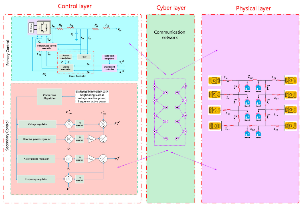
Here, the researchers considered that the DGs consisted of the communication and control agents on the Internet of Energy realm, as described in Figure 1. The physical components of a general microgrid included the inverter-interfaced distributed generator [Like photovoltaic, wind turbine and energy storage systems], dynamic and static loads and the diesel generators [25,26]. It was noted that a framework controlled the DGs in a microgrid, wherein one MAS agent managed every DG. The MAS agents communicate by Local Area Network (LAN) and can access the Internet for remotely controlling the microgrid via the cloud servers. In the Energy Internet, every distributed generator/microgrid was managed by various stakeholders and their controllers on the MAS/agents differed from MG components. It was expected that the number of the distributed generator and MG agents could be changed online. Hence, a remote, flexible and distributed control and implementation framework were necessary. Figure 1 presents the structure of proposed system.
The smart grid would need an effective measuring and communication system to continuously track the power and cost profile and regularly quantify power losses. There are several stages of data processing.
This work contains measurement units (MU) for every distribution network bus. MU is MATLAB modeling. Power and cost information is sent to the control center regularly at a fixed time. The control center is designed as a virtual data management and analysis platform. One approach to communication relating to the device topology proposed is considered. The case takes a Cloud approach, which sends its measured data directly to the cloud by any MU connected to the corresponding feeder bus, as illustrated in Figure 1.
The data transfer among the MATLAB software package and the open-source IoT framework ThingSpeak are used to model proposed communication architectures. ThingSpeak was chosen for the simulation of real-time cloud communication Due to its following benefits [27]:
  • ThingSpeak Cloud IoT platform data aggregation, tracking and analysis. In the smart grid model, the power profile is monitored on multiple ThingSpeak channels in real-time and depicted graphically.
  • Security: The Username and password allow user authentication while each channel is equipped with its ID and accessible (see by other users). There are two keys in each channel for the application programming interface. A randomly generated read key and write key of the API. These keys can save or retrieve information from stuff from each channel over the Internet or LAN.
  • It facilitates the double-way flow of data between the user and virtual device and allows data and remote control to be exchanged in real-time. The MATLAB Desktop Toolbox offers communication between the simulated feeding model and the ThingSpeak IoT platform.
  • Communication network enabling for the data transmission over the Internet between MATLAB and ThingSpeak.
  • Allows importing, exporting, analyzing and viewing data on multiple platforms and their fields simultaneously.

3. Proposed Hierarchical Control

Figure 2 illustrates the overall diagram of the proposed distributed hierarchical control. This control diagram has three main control levels: (a) primary control, (b) secondary distributing control and (c) tertiary mode control.

3.1. Problem Formulation

This paper considered an MG with N controllable distributed generator (indexed as I = 1, 2,…, N). The MGs electrical network is presented using an elaborate weighted graph, T =   V T ,   E T , wherein the nodes V T =   v 1 ,   v 2 , v N represented the buses (DGs) and edges, E T V T × V T , represented line connections [28].

3.2. Primary Control of Inverter-Based Distributed Generators

The basic block diagram of the inverter-based distributed generator voltage-controlled source device is shown in Figure 3. The microgrid consists of many of these distributed generator units, synchronized to maintain a common voltage (generally reference) ( V r e f ) and frequency ( ω r e f ). As stated in the introduction, the primary controller alone is not powerful enough to resolve the frequency and voltage deviations of the individual distributed generator units in islanded mode. In an island mode of operation, secondary control is, therefore, necessary to restore frequency ( ω i ) and voltage ( v o i ) of each distributed generator unit to the nominal level [29]. We offer an inverter-based distributed generator unit equipped with the basic controller derived in the entire non-linear dynamic model [30]. Let i denote the angle of i th distributed generator reference frame concerning a common reference frame and satisfies the relation.
δ ˙ = ω i     ω c o m
where ω i is angular frequency of rotation of i th distributed generator while ω com represents same associated with common reference. Frequency and voltage droop characteristics exerted by the primary controller are regulated:
ω i = ω n i     m p i P i v o d i * = V i = V n i     n Q i Q i v o q i * = 0
k d p = m p i = Δ ω P m a x
k d q = n Q i = Δ E Q m a x
where m p i   and n Q i   are a droop coefficients, selection of which depends on active and the reactive power ratings of each distributed generator; ω i is angular frequency of i th distributed generator unit fixed by primary control; P i and Q i denote to active power (in k W ) and reactive power (in k V A r ) measured at the terminals of i th distributed generator; V n i and ω n i act as the reference signals to the primary controller [30]. The power controller is characterized by:
P ˙ i   =     ω c i P i + ω c i v o d i i o d i + v o q i i o q i Q ˙ i =     ω c i P i + ω c i v o d i i o d i + v o q i i o q i
where ω c i is low-pass filters cutoff frequency; v o q i ,   v o d i , i o q i , i o d i   are quadrature and direct components of v o i   and i o i respectively. The differential-algebraic equations of voltage controller are given as:
ϕ ˙ d i = v o d i *     v o d i ϕ ˙ q i = v o q i *     v o q i i l d i * = F i i o d i     ω b C f i v o q i + K p v i v o d i *     v o d i + K I v i ϕ d i i l q i * = F i i o q i + ω b C f i v o d i + K p v i v o q i *     v o q i + K I v i ϕ q i
where ϕ d i and ϕ q i are subsidiary status variables connected to voltages power PI controllers and where the nominal angular frequency is denoted by b. The current controller’s dynamics are also obtained as:
γ ˙ d i = i l d i *     i l d i γ ˙ q i = i q i *     i q i v i d i * =     ω b L f i i l q i + K P r i i l d i *     i l d i + K l c i γ d i v i q i * = ω b L f i i l d i + K P c i i l q i *     i l q i + K I c i γ q i
where γ d i   and γ q i are auxiliary states associated with the new control PI controllers. Finally, the output LC filter and output connector equations as shown in Figure 3. The following are mentioned;
{ i l d i =     R f L f i i d i + ω i i q q i + 1 L f i v i d i     1 L f i v o d i       i l q i =     R f L f i i q i     ω i i l d i + 1 L f i v i q i     1 L f i v o q i         v ˙ o d i = ω i v o q i + 1 C f i i l d i     1 c f i i o d i v ˙ o q i =     ω i v o d i + 1 C f i i l q i     1 C f i i o q i i o d i =     R c l L c i i o d i + ω i i o q i + 1 L c l v o d i     1 L c l v b d i i o q i =     R c i L c i i o q i     ω i i o d i + 1 L c i v o q i     1 L c i v b q i
where v b d i   and v b q i are direct microgrid bus voltage v b and quadrature elements, as shown in Figure 3. Now, Equations (1)–(8) can be expressed in a compact form describing the nonlinear, input-refined status-space model of the i th distributed generator unit:
x ˙ i = f i x i + g i x i u i + k i x i D i
y 1 i = v o d i = h 1 i x i
y 2 i = ω i = ω n i m p i P i = h 2 i x i + e i u i
where the state vector is given by:
x i = [ δ i , P i , Q i , ϕ d i , ϕ q i , γ d i ,   γ q i , i l d i , i l q i , v o d i , v o q i , i o d i , i o q i ] T ,
y i = y 1 i , y 2 i T = v o d i , ω i T denotes the output;
u i = u 1 i , u 2 i T = V n i , ω n i T represents the control input;
In addition, D i = ω c o m , v b d i , v b q i T symbolizes the known disturbance input

3.3. MASs Communication

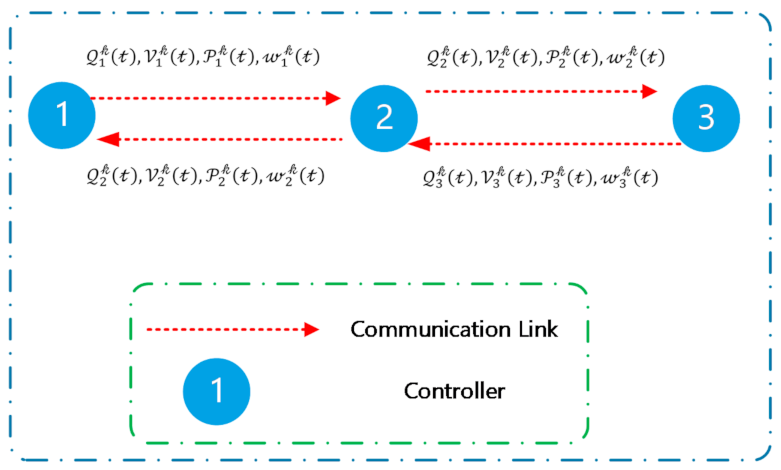
The communication networks of microgrid having N agents was represented using a graph: G =   V G , E G having a defined set of nodes V G =   v 1 , v 2 ,     v N and edges E G V G × V G . All nodes presented in the graph G (agents) showed a one-to-one correspondence to the nodes in the graph T (DGs). Furthermore, the edges in G , which represented the communication links for the data exchange, differed from the electrical connection seen in T . In addition, the set of neighbors described in the ith node of G was represented by N i   = v j V G : v i , v j E G . The researchers represented the adjacency matrix as a i j   R n × n . Here, the term a i j represented the information that was exchanged between the agents   i   and j , wherein a i j = 1 when agents i and j were connected with the edge ( v i , v j ) E G , else a i j = 0 . The researchers represented the Laplacian matrix as L =   l i j R n × n where each element l i j = i = 1 n a i j     a j i . They described the pinning matrix as G = d i a g g i R n × n and g i = 1 when the DG/agent could access the references ω r e f and V r e f , else g i = 0 . Figure 4 presents an example of the data exchange between the controllers.

3.4. Proposed Secondary Distributed Controller

Depending on feedback linearization process, secondary control of the droop controller distributed generator in the islanded microgrid was formulated in the following manner [2]:
ω i = ω i n o m     m i P P i
V i = V i n o m     n i Q Q i
ω i ˙ = ω ˙ n i     m p i P ˙ i = u i ω = ω ˙ i n o m     m p i P ˙ i
V ˙ n = V ˙ n i     n Q i Q ˙ i = u i V = V ˙ i n o m     n Q i Q ˙ i
The problem of accurate power sharing control can be formulated as m p i P ˙ i = u i P , n Q i Q ˙ i = u i Q . Then, the nominal setpoints nom ω i n o m and V i n o m   are determined by secondary control as:
ω i n o m = ω ˙ n i     m p i P ˙ i d t = u i ω + u i P d t
V i n o m = V ˙ n i     m p i Q ˙ i d t = u i V + u i Q d t
As observed from Equations (16) and (17), the secondary control inputs of u i ω and u i P control ω n o m , while the secondary control inputs of u i ω and u i Q control nom V n o m .
Here, the researchers have proposed a control framework having good flexibility and scalability on the Internet of Energy. Different distributed secondary control techniques were investigated earlier [2], wherein the researchers used a popular linear control protocol for every distributed generator. In the MAS having N agents, control protocol could be described as:
u i ω t = k i ω j = 1 N a i j ω j t     ω i t + g i ω r e f     ω i t
u i V t = k i V j = 1 N a i j V j t     V i t + g i V r e f     V i t
u i p t = k i p j = 1 N a i j p j t     p i t
u i Q t = k i Q j = 1 N a i j q j t     q i t
where i , j 1 , 2 , ,   n , p i = m i P P i   for simplicity,   q i = m i Q Q i the control gains k i ω , k i V , k i p   and k i Q   are all greater than zero.
The above Equations (18)–(21) can be described as:
u ω = k ω   L ω + G ω r e f 1 n × 1     ω
u V = k V   L V + G V r e f 1 n × 1     V
u P = k P   L p
u Q = k Q   L q
where the vectors u ω = u 1 ω ,     u n ω T , u V = u 1 V ,     u n V T , u p = u 1 P ,     u n P T , k ω = d i a g k 1 ω ,   k n ω , k V = d i a g k 1 V ,   k n V , k P = d i a g k 1 P ,   k n P and k Q = d i a g k 1 Q ,   k n Q .
Then, all control inputs from multi agent system can be given as [2]:
u ω u V u p u Q u R 4 n × 1 =     k ω 0 0 0 0 k V 0 0 0 0 k P 0 0 0 0 k Q K R 4 n × 4 n × L 0 0 0 0 L 0 0 0 0 L 0 0 0 0 L L ˜ R 4 n × 4 n × ω V P Q + k ω 0 0 0 0 k V 0 0 0 0 k P 0 0 0 0 k Q K R 4 n × 4 n × G 0 0 0 0 G 0 0 0 0 G 0 0 0 0 G G ˜ R 4 n × 4 n × ω r e f     ω V r e f     V P r e f     P Q r e f     Q   x r e f     x
u = K   L ˜ x + G ˜ x r e f     x
where u ,   x , x r e f ,   K ,   L ˜   a n d   G ˜ are vectors and matrices indicated in (26).
The researchers also considered a case where the MASs managed the large-scale MGs. It was noted that the cluster/hierarchical consensus algorithm offered a control solution for the large-scale multi-agent system. The researchers stated that this control algorithm was sufficient for the scalable and flexible control of numerous MASs after considering the inter and intra multi-agent system interactions. Without any loss of generality, the researchers simplified representation after considering that no. of agents in every multi-agent system was similar. This proposed technique could be applied to a heterogeneous condition. Finally, the researchers proposed a feedback control protocol as follows:
u 1 u 2 u m =     K L ˜   0 0 0   K L ˜ 0           0     0 K L ˜ × x 1 x 2 x m I n t r a     M A S     l ^ 11 Δ   l ^ 12 Δ l ^ 1 m Δ l ^ 21 Δ   l ^ 22 Δ l ^ 2 m Δ     0   l ^ m 1 Δ     l ^ m 2 Δ l ^ m m Δ × x 1 x 2 x m I n t e r     M A S + K G ˜   0 0 0   K G ˜ 0           0     0 K G ˜ × x r e f     x 1 x r e f     x 2 x r e f     x m P i n n i n g   N o d e s
where matrix Δ R 4 n × 4 n defines which agents have data exchange among each agent. For simplicity, this paper considers Δ = K G ˜ . The Laplacian matrix L ^ = l ^ i j R m × m indicates the interactions among groups. In compact form, (28) can be represented as:
U =     I m K L ˜ + L ^ Δ X + I m K G ˜ X r e f     X = I m K [     I m L ˜ + L ^ G ˜ X + I m G ˜ X r e f     X  
where:
U = u 1 , ,   u m T ,   X = x 1 , ,   x m T ,   X r e f = 1 n × 1 x r e f
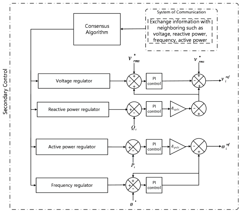
The schematic diagram of the proposed method for multi-agent MG has been shown in Figure 5. The flowchart of the proposed controller has been introduced in Figure 6.

4. Proposed Internet of Energy Communication Platform

The decentralized controller of a smart MG helps manage the system operating conditions if there is some disturbance. Furthermore, IoT technology can be used for communicating between the appliances present in smart homes, central controllers or power management centers. The researchers proposed the IoT platform for collecting the data, monitoring, managing and controlling the SMG. This platform included and connected all appliances and energy resources. Including the energy supply layer, network layer, energy management layer, energy appliance layer, control system layer and the IoT service layer, the primary IoT platform layers.

4.1. MQTT Knowledge

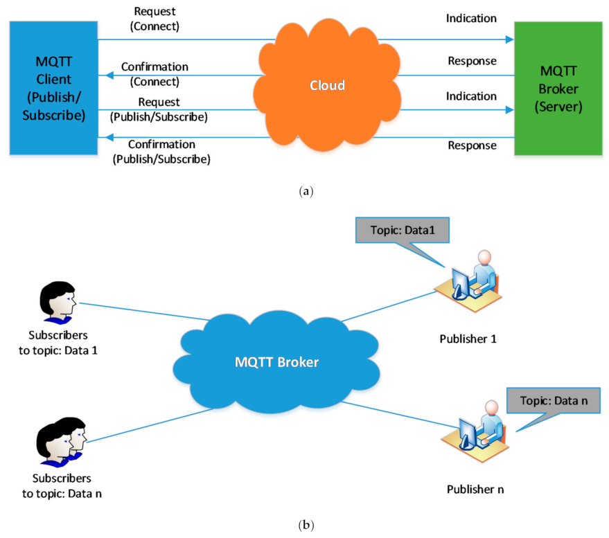
Message Queuing Telemetry Transport (MQTT) is a lightweight protocol that makes effective use of the network bandwidth with a fixed header of 2 bytes. The MQTT is operational on the TCP and ensures that all messages are sent from agent to server.
Three main players, MQTT broker, MQTT publisher and a MQTT subscriber, are included in the protocol. The MQTT subscriber and publisher are indirectly linked and do not use one IP address simultaneously. The MQTT Broker refers to a network gateway that filters, receives, prioritizes and distributes the publishers’ messages to the thousands of simultaneously-connected MQTT subscribers. An MQTT broker takes care of the customer authorization and initialization process necessary for communication. To publish the information, the MQTT publishers utilize custom themes for catering to their clients. The MQTT protocol did not use Metadata marking. After that, the MQTT topic management presents the metadata for a message load, which is considerable and it can attach meaningful attributes to the topic. MQTT is seen to be a string having a multi-attribute and multi-level hierarchical structure. The forward slash in a theme tree can separate every stage [31]. All subjects could be updated for deriving the routing data. Figure 7a presents the connection’s initialization after exchanging the control packets between the clients and brokers. It was noted that the check packets for the CONNAC, Link, PUBACK, PUBLISH, SUBSCRIBE, SUBACK, etc., comprise specific instructions regarding the theme, transmission and the payload Quality of Service (QoS). Figure 7b presents all components of the MQTT contact.

4.2. Architecture of Proposed System

Figure 8 presents an overview of smart homes’ hierarchical platform with a cyber layer, physical layer and control layer. Two communication layers were included in the hybrid platform. It was seen that in Layer one (local layer), the appliances in the smart building transmitted the MQTT messages to a Building MQTT Client (BMC) and reported the events/measurements and subscribed to the MQTT messages that BMC published for the protection/control purpose. Layer two (global layer) represented the interaction between the cloud and BMC with the HTTP GET/POST requests’ help. In this architecture, every appliance was equipped with a Wi-Fi module connected to the local gateway. Thus, it could periodically publish the values of a dedicated and pre-defined topic. After that, the BMC subscribes to the different issues and posts the received values to the cloud channel. The cloud data can be accessed by the cloud MATLAB interface, which implements the designed appliance resource allocation algorithm. The results of the algorithm are then moved from a cloud into intelligent BMC devices which controls the devices. The researchers found that if communication failure occurs in any layer, the architecture proposed is resilient (either local or global). BMC was therefore developed to operate as a local controller (or a backup controller) for all devices in the building during any communication link failure or high network latency noted. The results section highlighted this function of the BMC.

5. Result analysis and Discussion Proposed Method

The proposed controller is tested with the microgrid model illustrated in Figure 1. The system and control parameter are listed in Table 1.
Here, the researchers have described the simulated implementation of the distributed secondary controller on a multi-agent system platform, in addition, to their correlation with the cloud server and LAN. Figure 3 presents the MAS platform structure. The multi-agent system was implemented in the MATLAB cluster connected to LAN via the network switch and connected to the cloud server by the Internet. Local communication was carried out by the TCP/IP protocol, whereas the TCP protocol conducted the communication between the cloud server and MAS. Communication between the agents was in the form of a client/server format with the help of ThingSpeak and could be configured for any network topology. In the ThingSpeak-based communication system, every agent acted as the server which waits for the incoming messages. It can also dispatch the messages to a corresponding technique since it was the neighboring servers’ client.
This part discusses the effect of the Microgrid communication system. The microgrid will exchange information in the communications device’s presence, such as load consumption and power generation. The microgrid gets the required energy from neighboring agents to regulate active power, reactive power, voltage and frequency. On the other hand, the communication system provides the required information for the microgrid to transfer energy.
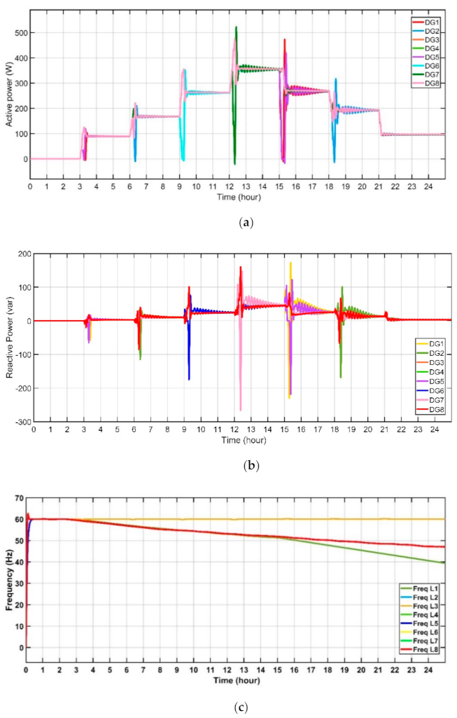
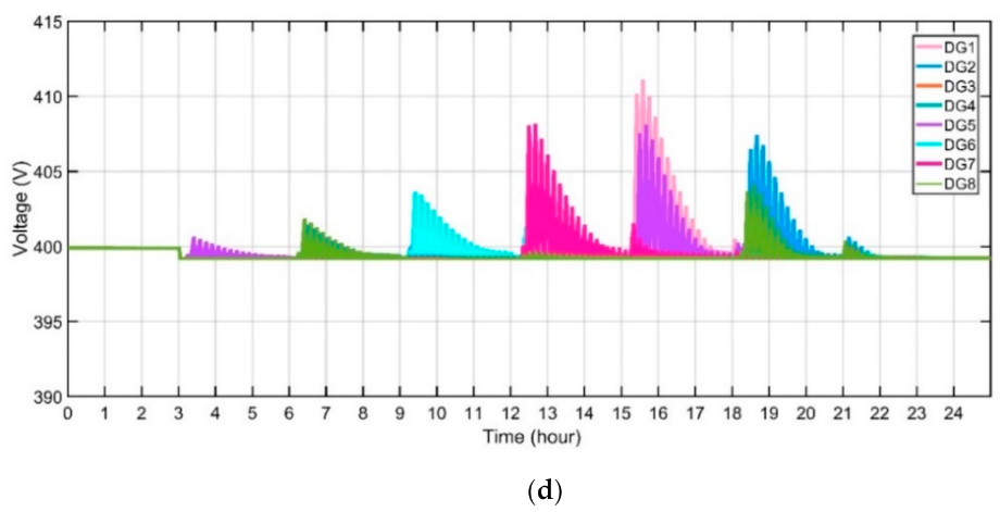
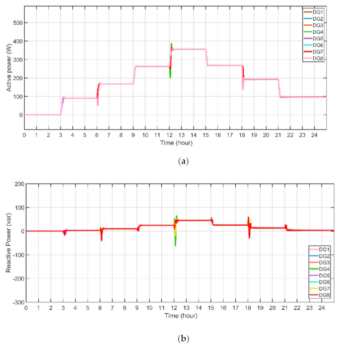
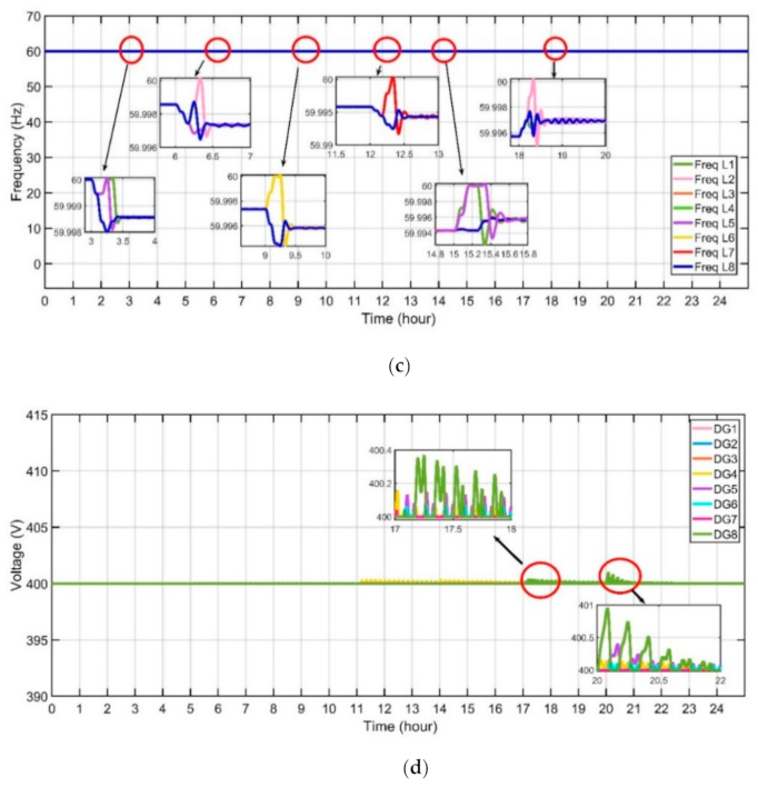
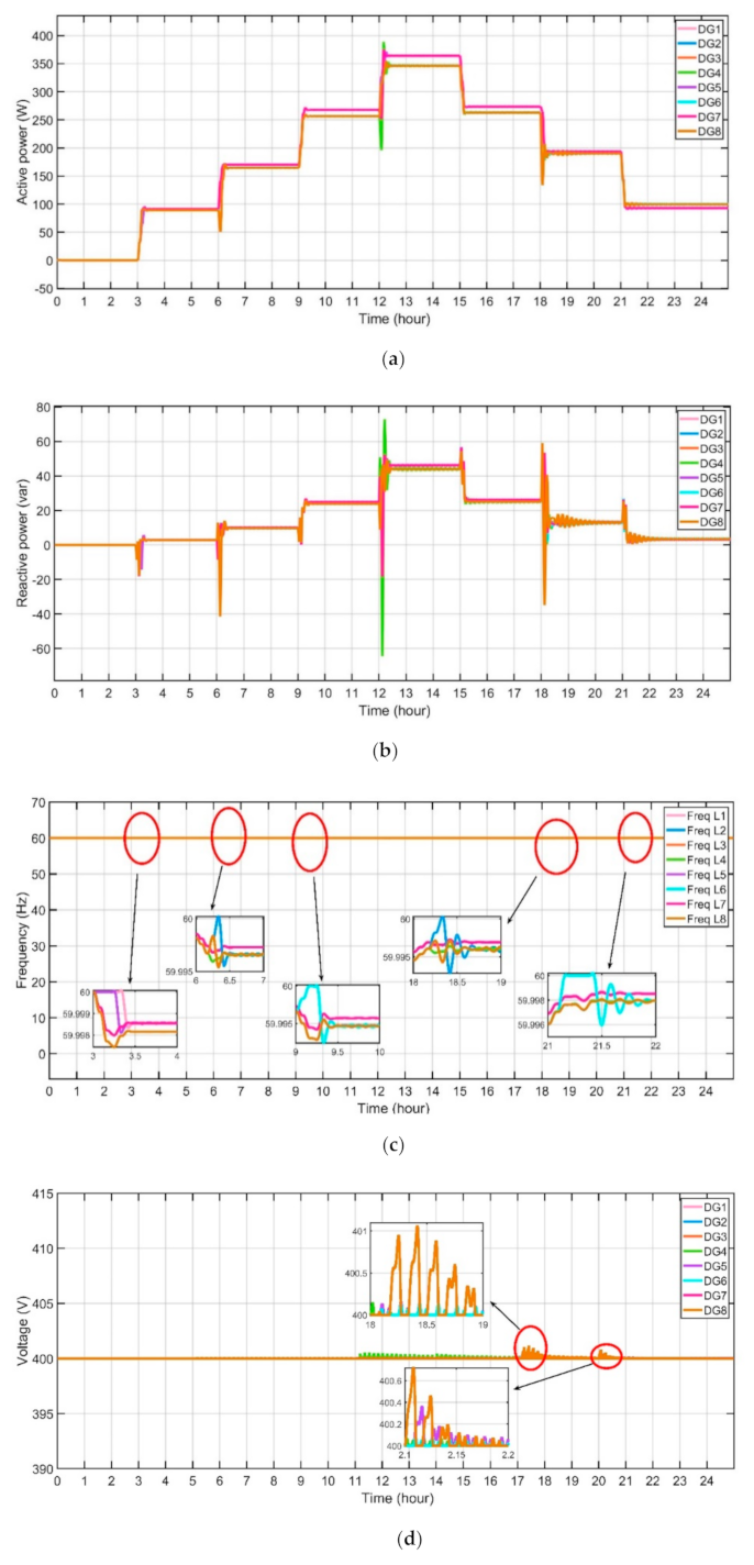
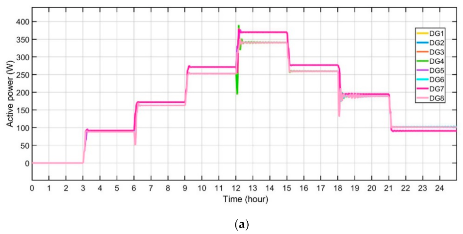
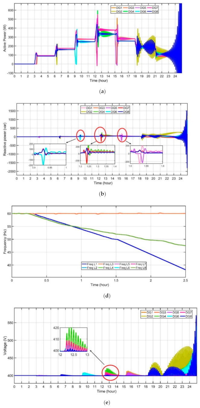
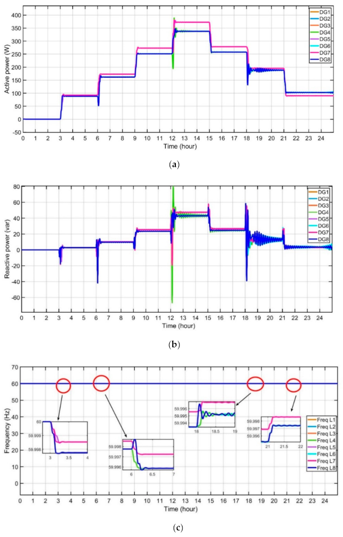
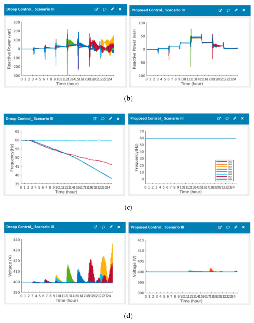
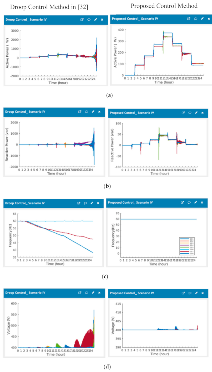
The experimental results noted in MATLAB for the power, voltage and actual power of every DG have been presented in Figure 9, Figure 10, Figure 11, Figure 12, Figure 13, Figure 14, Figure 15 and Figure 16. The results described in Figure 10, Figure 12, Figure 14 and Figure 16 indicated that the real power, reactive power, frequency and voltage are restored to their reference values after applied proposed control. All distributed generator in the microgrid autonomously alters their power output for fulfilling the load demands. Results for Scenarios I, II, III and IV indicated that a cloud server’s distributed MAS control for the remote microgrid was an effective technique. Table 2 presents the scheduling and operating activities of all the loads.
The proposed method was simulated in three different scenarios in the MATLAB environment to assess the proposed strategy performance. The scenario I is performed in eight inverters with the same drop coefficients. In contrast, different droop coefficients are applied for scenarios II, scenario III and scenario IV. In both cases, the proposed approach is compared with another control method. Table 1 includes the device parameters for simulations.

5.1. Scenario I

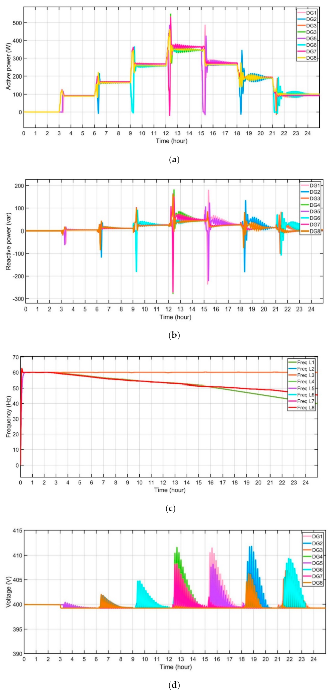
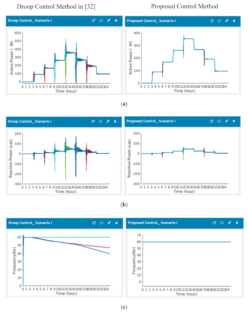
This scenario examines the proposed method capability after islanding takes place at t = 3 h. At 3 h Home 1 and home 5 are connecting to the MG. At 6 h Home 2 and Home 8 are connected to the MG, at 9 h Home 3 and Home 6 are connecting to MG a and at 12-h, Home 4 and Home 7 are connecting to MG. While Home 1 and home 5 are disconnected from the MG at 15-h, Home 2 and Home 8 are disconnected from the MG at 18-h, Home 3 and Home 6 are disconnected from MG at 21 h. In this scenario m p = n q = 1 × 10     4 .
The results of this scenario I were presented in Figure 9. It is visible from Figure 10 that the proposed control method can modify the frequency, active power ratio, reactive power and voltage following significant disturbances, such as load changes and reconfiguration of microgrid structures. In contrast, accurate real power-sharing is guaranteed in a steady state.
Figure 9a indicates the active power of the distributed generators using the droop control method in [32], Figure 9b represents the reactive power of the distributed generators using the droop control method, Figure 9c illustrate the frequency of the loads using droop control method in [32], Figure 9d, represents the voltage of the distributed generators using droop control method in [32]. Whereas Figure 10a indicates the active power of the distributed generators using the proposed control method, Figure 10b represents the reactive power of distributed generators using the proposed control method, Figure 10c illustrate the frequency of the loads using proposed control method, Figure 10d, represents the voltage of the distributed generators using proposed control method.

5.2. Scenario II

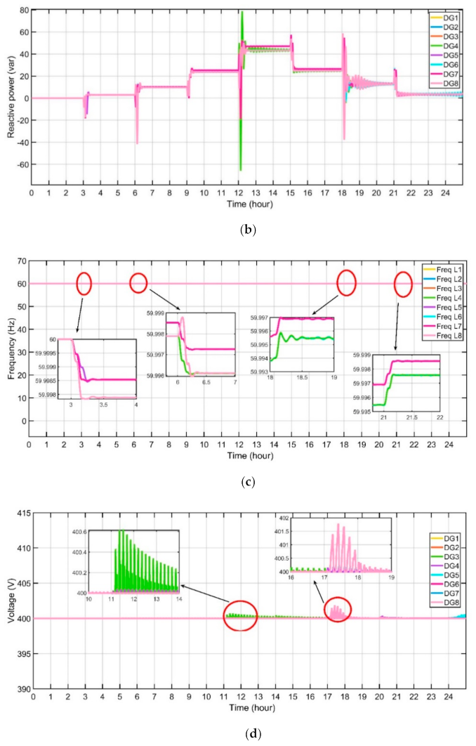
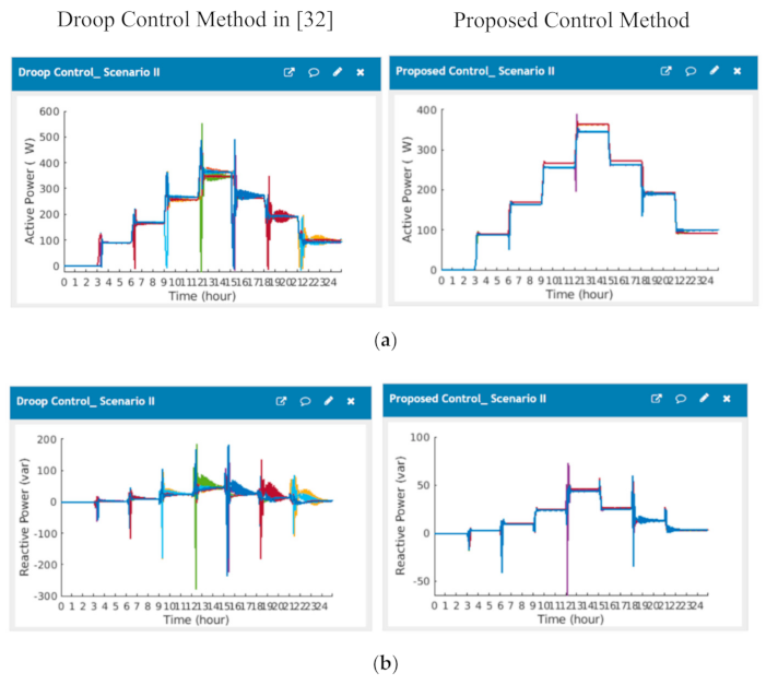
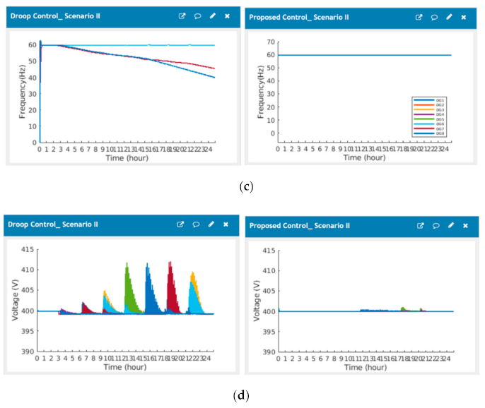
In this scenario, droop coefficients are not equal to each other; in this scenario m p = 1 × 10     4 and n q = 1.3 × 10     4 . The results of this scenario II were showed in Figure 11 and Figure 12. Figure 11a indicates the active power of the distributed generators using the droop control method in [32], Figure 11b represents the reactive power of the distributed generators using the droop control method in [32], Figure 11c shows the frequency of the loads using droop control method in [32], Figure 11d, represents the voltage of the distributed generators using droop control method in [32]. Whereas Figure 12a indicates the active power of the distributed generators using the proposed control method, Figure 12b represents reactive power of distributed generators using the proposed control method, Figure 12c illustrate the frequency of loads using the method of proposed control, Figure 12d, represents the voltage of distributed generators using proposed control method.

5.3. Scenario III

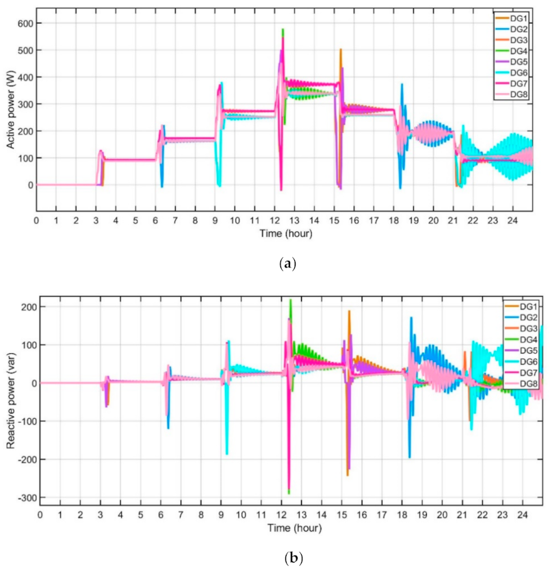
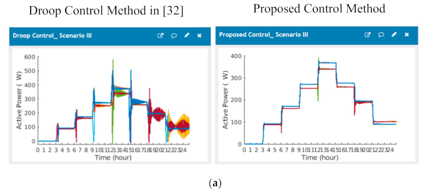
In this scenario, droop coefficients are not equal to each other; in this scenario m p = 1 × 10     4 and n q = 1.6 × 10     4 . The results of this scenario III were showed in Figure 13 and Figure 14. Figure 13a indicates the active power of distributed generators using the droop control method, Figure 13b represents the reactive power of distributed generators utilizing the method of droop control in [32], Figure 13c illustrates the frequency of loads using the method of droop control in [32]; Figure 13d represents the voltage of the distributed generators using droop control method in [32]. Whereas Figure 14a indicates the active power of the distributed generators using the proposed control method, Figure 14b represents reactive power of the distributed generators utilizing the method of proposed control; Figure 14c illustrates the frequency of loads using proposed control method; Figure 14d, represents the voltage of the distributed generators using proposed control method.

5.4. Scenario IV

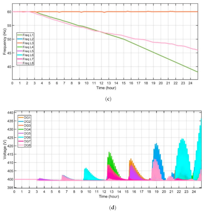
In this scenario, droop coefficients are not equal to each other; in this scenario m p = 1 × 10     4 and n q = 2 × 10     4 . The results of this scenario I were showed in Figure 15 and Figure 16. Figure 15a indicates the active power of the distributed generators using the droop control method in [32]; Figure 15b represents the reactive power of the distributed generators utilizing the method of droop control in [32]; Figure 15c shows the frequency of the loads using droop control method in [32]; Figure 15d, represents the voltage of the distributed generators using droop control method in [32]. Whereas Figure 16a indicates to active power of the distributed generators using the proposed control method, Figure 16b represents the reactive power of the distributed generators using the proposed control method, Figure 16c illustrates the frequency of the loads using the method of proposed control, Figure 16d represents the voltage of distributed generators using proposed control method.

6. Access to Internet Web Page

In this study, the researchers carried out a simulation test, where they described and discussed the results of a decentralized power management and control strategy for the microgrid in the Energy Internet paradigm, which was implemented using the proposed algorithm over the cloud platform for regulating the appliances in a smart home. As noted in the software communication and architecture interface, a MATLAB program was present for the Main Command and Control Unit (MCCU), which helped organize all ThingSpeak platforms. The MQTT (Mosquitto) functions as a broker and bridges the home appliance subscription and MCCU publishers’ gap. For regulating the home appliances through the MQTT gateway, the researchers used a custom code derived from the proposed MATLAB-based algorithm for its deployment. Here, the researchers designed a ThingSpeak dashboard interface, using a simple and effective user interface (UI), which allowed the homeowners to access and interact with the home energy management service over the cloud system. Figure 17 presents an internet web page that can be accessed in any internet browser after entering and providing their username and password in the uniform resource locator (URL).
The proposed system’s effectiveness of proposed distributed control for remote islanded microgrid via cloud server is validated. The simulation begins with Home 1 and home 5 are connecting to the MG at 3 h. Home 2 and Home 8 are connected to the MG at 6 h, Home 3 and Home 6 are connecting to MG at 9 h and Home 4 and Home 7 is connecting to MG at 12 h. While Home 1 and Home 5 are disconnected from the MG at 15 h, Home 2 and Home 8 are disconnected from the MG at 18 h, Home 3 and Home 6 are disconnected from MG at 21 h.

6.1. Scenario I

In this scenario, droop coefficients m p = n q = 1 × 10     4 . This scenario I presented in Figure 18 using the droop control method in [32] and using the proposed control method. Whereas Figure 18a indicates the active power of the distributed generators, Figure 18b represents the reactive power of the distributed generators, Figure 18c illustrates the frequency of the loads, Figure 18d shows the voltage of the distributed generators.

6.2. Scenario II

In this scenario, droop coefficients m p = 1 × 10     4 and n q = 1.3 × 10     4 . This scenario I presented in Figure 19 using the droop control method in [32] and using the proposed control method. Whereas Figure 19a indicates the active power of the distributed generators, Figure 19b represents the reactive power of the distributed generators, Figure 19c illustrates the frequency of the loads and Figure 19d shows the voltage of the distributed generators.

6.3. Scenario III

In this scenario, droop coefficients m p = 1 × 10     4 and n q = 1.6 × 10     4 . The results of this scenario III were presented in Figure 20 using the droop control method and using the proposed control method. Whereas Figure 20a indicates the active power of the distributed generators, Figure 20b represents the reactive power of distributed generators, Figure 20c illustrates the frequency of the loads and Figure 20d shows the voltage of the distributed generators.

6.4. Scenario IV

In this scenario, droop coefficients m p = 1 × 10     4 and n q = 2 × 10     4 . This scenario IV’s results were presented in Figure 21 using the droop control method and using the proposed control method. Where Figure 21a indicates the active power of the distributed generators, Figure 21b represents the reactive power of the distributed generators, Figure 21c illustrates the frequency of the loads, Figure 21d shows the voltage of the distributed generators.
Lastly, to show the effectiveness of the expressed cooperative proposed control protocol, the proposed algorithm is compared with other reported techniques [21,32] and present the results in Figure 9, Figure 10, Figure 11, Figure 12, Figure 13, Figure 14, Figure 15 and Figure 16, when the microgrid faces with the load change, the controller has a good performance and the voltage and frequency waveforms are stably regulated to the nominal values.
The main objective of the comparison between the proposed method and methods in [21,32] is to prove the proposed controller’s efficiency.
The distributed control method [21] fails to regulate the microgrid’s active power and reactive power. The proposed protocols in [21] fail to provide a web page to monitor DGs’ active power, reactive power of DGs, frequency of loads and voltages of DGs.
In addition, compared with the well-known conventional distributed method [32], as seen from Figure 9, Figure 11, Figure 13 and Figure 15, when the microgrid faces the load change, the voltage and frequency waveforms become incredibly faulty. Therefore, the conventional distributed method [32] deteriorates the synchronization of voltage magnitude, frequency and real power ratio due to system faults. In addition, the control method in [32] fails to regulate the microgrid’s active power and reactive power. The proposed protocols in [32] fail to provide a web page to monitor DGs’ active power, reactive power of DGs, frequency of loads and voltages of DGs.
Therefore, our proposed method has a better, robust, resilient, acceptable and desirable performance, even if the load change is excellent. Thus, the proposed protocols’ capability to meet the requirement of voltage, frequency, active power and reactive power events is verified. In addition, our proposed protocols providing a web page to monitor the active power DGs, reactive power of DGs, frequency of loads and voltages of DGs.

7. Conclusions

The researchers proposed a novel distributed control framework for the MGs controlled by the various multi-agent system in this study. The proposed control law defines the data exchange within and among MASs to enable MG’s flexible control in Energy Internet. The proposed control objectives are achieved with the evaluation of the stability considering network latency. The proposed controller depends on the information transferring between the connected agents in the MG system. The errors in frequency and voltage waveforms have been compensated by applying the proposed consensus controller. In addition, the active and reactive power is optimally shared among the DGs. The proposed controller improves the performance of the primary droop control method that can’t adjust the MG-VF to their nominal values, and also, it does not enhance the power-sharing among the DGs in MG. A hypothetical multi-agent MG system is designed to prove the proposed controller’s effectiveness using the MATLAB/Simulink environment in the presence of the different scenarios in MG. In addition, this study presents a hierarchical communication platform with a two-level structure, which is suitable for the microgrid management system. The proposed platform uses Transmission Control Protocol/Internet Protocol (TCP/IP) for local microgrid data exchange and as a backup communication method among microgrids in case of a failure in the cloud level communication.
Message Queuing Telemetry Transport (MQTT) subscriber/publisher is adopted for cloud level messaging and HTTP TCP/IP for interactions between a cloud-server and the platform. The cost analysis provided in the simulation results section shows the efficiency of the proposed distributed communication platform compared to the centralized operation of the Microgrid communications. We also compared our proposed techniques with some of the existing methods and simulation results prove the efficacy of this paper’s presented methodologies. The obtained results showed that the proposed controller regulates the frequency and voltage in MG under different faults. In addition, active and reactive power is equally shared between the DGs. Finally, for accessing the data related to the power consumption of the individual loads, the researchers developed a reliable web portal associated with the IoT environment. They provided a Graphical User Interface (GUI) after plotting a graph of power consumption for determining the daily power usage of every appliance. They further provided a database for efficient energy management, which could be used for analyzing the data. The proposed method can regulate the voltage and frequency well within the operational requirements. Furthermore, the flexibility and scalability of the approach are demonstrated in MG with eight DGs.

Author Contributions

B.N.A.: writing—original draft, software, methodology and validation; B.H.J.: supervision, formal analysis, investigation, resources, writing—review and editing; B.E.S.: writing—review and editing; E.H.: supervision, funding, writing—review and editing, J.M.G.: supervision, writing—review and editing. All authors have read and agreed to the published version of the manuscript.

Funding

This research received no external funding.

Conflicts of Interest

The authors declare no conflict of interest.

References

  1. Fan, B.; Wang, X. Distributed Privacy-Preserving Active Power Sharing and Frequency Regulation in Microgrids. IEEE Trans. Circuits Syst. 2020, 1–5. [Google Scholar] [CrossRef]
  2. Wang, Y.; Nguyen, T.L.; Syed, M.H.; Xu, Y.; Guillo-Sansano, E.; Nguyen, V.-H.; Burt, G.M.; Tran, Q.-T.; Caire, R. A Distributed Control Scheme of Microgrids in Energy Internet Paradigm and Its Multisite Implementation. IEEE Trans. Ind. Inform. 2021, 17, 1141–1153. [Google Scholar] [CrossRef] [Green Version]
  3. Hou, X.; Sun, Y.; Lu, J.; Zhang, X.; Koh, L.H.; Su, M.; Guerrero, J.M. Distributed Hierarchical Control of AC Microgrid Operating in Grid-Connected, Islanded and Their Transition Modes. IEEE Access 2018, 6, 77388–77401. [Google Scholar] [CrossRef]
  4. Shafiee, Q.; Guerrero, J.M.; Vasquez, J.C. Distributed Secondary Control for Islanded Microgrids—A Novel Approach. IEEE Trans. Power Electron. 2014, 29, 1018–1031. [Google Scholar] [CrossRef] [Green Version]
  5. Zhang, C.; Xu, Y.; Dong, Z.Y.; Yang, L.F. Multitimescale Coordinated Adaptive Robust Operation for Industrial Multienergy Microgrids With Load Allocation. IEEE Trans. Ind. Inform. 2019, 16, 3051–3063. [Google Scholar] [CrossRef]
  6. Alhasnawi, B.N.; Jasim, B.H. A New Coordinated Control of Hybrid Microgrids with Renewable Energy Resources Under Variable Loads and Generation Conditions. Iraqi J. Electr. Electron. Eng. 2020, 16, 1–20. [Google Scholar] [CrossRef]
  7. Molzahn, D.K.; Dorfler, F.; Sandberg, H.; Low, S.H.; Chakrabarti, S.; Baldick, R.; Lavaei, J. A Survey of Distributed Optimization and Control Algorithms for Electric Power Systems. IEEE Trans. Smart Grid 2017, 8, 2941–2962. [Google Scholar] [CrossRef]
  8. Wang, Y.; Xu, Y.; Tang, Y.; Syed, M.H.; Guillo-Sansano, E.; Burt, G.M. Decentralised-distributed hybrid voltage regulation of power distribution networks based on power inverters. IET Gener. Transm. Distrib. 2019, 13, 444–451. [Google Scholar] [CrossRef]
  9. Ge, X.; Yang, F.; Han, Q.-L. Distributed networked control systems: A brief overview. Inf. Sci. 2017, 380, 117–131. [Google Scholar] [CrossRef]
  10. Eskandari, M.; Li, L.; Moradi, M.H.; Siano, P.; Blaabjerg, F. Active Power Sharing and Frequency Restoration in an Autonomous Networked Microgrid. IEEE Trans. Power Syst. 2019, 34, 4706–4717. [Google Scholar] [CrossRef]
  11. Awal, M.A.; Yu, H.; Tu, H.; Lukic, S.M.; Husain, I. Hierarchical Control for Virtual Oscillator Based Grid-Connected and Islanded Microgrids. IEEE Trans. Power Electron. 2020, 35, 988–1001. [Google Scholar] [CrossRef]
  12. Weng, S.; Yue, D.; Dou, C.; Shi, J.; Huang, C. Distributed Event-Triggered Cooperative Control for Frequency and Voltage Stability and Power Sharing in Isolated Inverter-Based Microgrid. IEEE Trans. Cybern. 2019, 49, 1427–1439. [Google Scholar] [CrossRef]
  13. Ding, L.; Han, Q.-L.; Zhang, X.-M. Distributed Secondary Control for Active Power Sharing and Frequency Regulation in Islanded Microgrids Using an Event-Triggered Communication Mechanism. IEEE Trans. Ind. Inform. 2019, 15, 3910–3922. [Google Scholar] [CrossRef]
  14. Mortezaei, A.; Simoes, M.G.; Savaghebi, M.; Guerrero, J.M.; Al-Durra, A. Cooperative Control of Multi-Master–Slave Islanded Microgrid With Power Quality Enhancement Based on Conservative Power Theory. IEEE Trans. Smart Grid 2016, 9, 2964–2975. [Google Scholar] [CrossRef] [Green Version]
  15. Diaz, N.L.; Luna, A.C.; Vasquez, J.C.; Guerrero, J.M. Centralized Control Architecture for Coordination of Distributed Renewable Generation and Energy Storage in Islanded AC Microgrids. IEEE Trans. Power Electron. 2017, 32, 5202–5213. [Google Scholar] [CrossRef] [Green Version]
  16. Xu, Y.; Sun, H.; Gu, W.; Xu, Y.; Li, Z. Optimal Distributed Control for Secondary Frequency and Voltage Regulation in an Islanded Microgrid. IEEE Trans. Ind. Inform. 2019, 15, 225–235. [Google Scholar] [CrossRef]
  17. Liu, X.-K.; Jiang, H.; Wang, Y.-W.; He, H. A Distributed Iterative Learning Framework for DC Microgrids: Current Sharing and Voltage Regulation. IEEE Trans. Emerg. Top. Comput. Intell. 2018, 4, 119–129. [Google Scholar] [CrossRef]
  18. Coelho, E.A.A.; Wu, D.; Guerrero, J.M.; Vasquez, J.C.; Dragicevic, T.; Stefanovic, C.; Popovski, P. Small-Signal Analysis of the Microgrid Secondary Control Considering a Communication Time Delay. IEEE Trans. Ind. Electron. 2016, 63, 6257–6269. [Google Scholar] [CrossRef] [Green Version]
  19. Zhang, R.; Hredzak, B. Distributed Finite-Time Multiagent Control for DC Microgrids with Time Delays. IEEE Trans. Smart Grid 2019, 10, 2692–2701. [Google Scholar] [CrossRef]
  20. Dou, C.; Yue, D.; Han, Q.-L.; Guerrero, J.M. Multi-Agent System-Based Event-Triggered Hybrid Control Scheme for Energy Internet. IEEE Access 2017, 5, 3263–3272. [Google Scholar] [CrossRef]
  21. Shahab, M.A.; Mozafari, B.; Soleymani, S.; Dehkordi, N.M.; Shourkaei, H.M.; Guerrero, J.M. Distributed Consensus-Based Fault Tolerant Control of Islanded Microgrids. IEEE Trans. Smart Grid 2020, 11, 37–47. [Google Scholar] [CrossRef]
  22. Yoo, H.-J.; Nguyen, T.-T.; Kim, H.-M. Consensus-Based Distributed Coordination Control of Hybrid AC/DC Microgrids. IEEE Trans. Sustain. Energy 2020, 11, 629–639. [Google Scholar] [CrossRef]
  23. Wu, X.; Xu, Y.; He, J.; Wang, X.; Vasquez, J.C.; Guerrero, J.M. Pinning-Based Hierarchical and Distributed Cooperative Control for AC Microgrid Clusters. IEEE Trans. Power Electron. 2020, 35, 9865–9885. [Google Scholar] [CrossRef]
  24. Wang, Y.; Nguyen, T.-L.; Xu, Y.; Tran, Q.-T.; Caire, R. Peer-to-Peer Control for Networked Microgrids: Multi-Layer and Multi-Agent Architecture Design. IEEE Trans. Smart Grid 2020, 11, 4688–4699. [Google Scholar] [CrossRef]
  25. Afshari, A.; Karrari, M.N.; Baghaee, H.R.; Gharehpetian, G.B. Distributed Fault-Tolerant Voltage/Frequency Synchronization in Autonomous AC Microgrids. IEEE Trans. Power Syst. 2020, 35, 3774–3789. [Google Scholar] [CrossRef]
  26. Alhasnawi, B.N.; Jasim, B.H.; Esteban, M.D. A New Robust Energy Management and Control Strategy for a Hybrid Microgrid System Based on Green Energy. Sustainability 2020, 12, 5724. [Google Scholar] [CrossRef]
  27. Forcan, M.; Maksimović, M. Cloud-Fog-based approach for Smart Grid monitoring. Simul. Model. Pract. Theory 2020, 101, 101988. [Google Scholar] [CrossRef]
  28. Qiu, H.; Zhao, B.; Gu, W.; Bo, R. Bi-Level Two-Stage Robust Optimal Scheduling for AC/DC Hybrid Multi-Microgrids. IEEE Trans. Smart Grid 2018, 9, 5455–5466. [Google Scholar] [CrossRef]
  29. Alhasnawi, B.N.; Jasim, B.H.; Anvari-Moghaddam, A.; Blaabjerg, F. A New Robust Control Strategy for Parallel Operated Inverters in Green Energy Applications. Energies 2020, 13, 3480. [Google Scholar] [CrossRef]
  30. Hu, J.; Bhowmick, P. A consensus-based robust secondary voltage and frequency control scheme for islanded microgrids. Int. J. Electr. Power Energy Syst. 2020, 116, 105575. [Google Scholar] [CrossRef]
  31. Alhasnawi, B.N.; Jasim, B.H.; Esteban, M.D.; Guerrero, J.M. A Novel Smart Energy Management as a Service over a Cloud Computing Platform for Nanogrid Appliances. Sustainability 2020, 12, 9686. [Google Scholar] [CrossRef]
  32. Bidram, A.; Davoudi, A.; Lewis, F.L.; Qu, Z. Secondary control of microgrids based on distributed cooperative control of multi-agent systems. IET Gener. Transm. Distrib. 2013, 7, 822–831. [Google Scholar] [CrossRef] [Green Version]
Figure 1. Structure of the proposed system.
Energies 14 02183 g001
Figure 2. Proposed distributed hierarchical control scheme.
Energies 14 02183 g002
Figure 3. Schematic of primary control.
Energies 14 02183 g003
Figure 4. Example of the information exchange among controllers.
Energies 14 02183 g004
Figure 5. Diagram of proposed method in multi-agent MG.
Energies 14 02183 g005
Figure 6. The proposed method flowchart.
Energies 14 02183 g006
Figure 7. (a) MQTT Procedure, (b) MQTT Topic and Component.
Energies 14 02183 g007
Figure 8. Smart home proposed architecture of communication.
Energies 14 02183 g008
Figure 9. Performance evaluation of the control method in [32] for distributed generators in the scenario I, (a) active power of distributed generator, (b) reactive power of distributed generator, (c) frequency of loads and (d) voltage of the distributed generator.
Energies 14 02183 g009aEnergies 14 02183 g009b
Figure 10. Performance evaluation of the proposed protocol for distributed generators in the scenario I, (a) active power of distributed generator, (b) reactive power of distributed generator, (c) frequency of loads and (d) voltage of the distributed generator.
Energies 14 02183 g010aEnergies 14 02183 g010b
Figure 11. Performance evaluation of the control method in [32] for distributed generators in the scenario II, (a) active power of the distributed generator, (b) reactive power of distributed generator, (c) frequency of loads and (d) voltage of the distributed generator.
Energies 14 02183 g011
Figure 12. Performance evaluation of the proposed protocol for distributed generators in the scenario II, (a) active power of distributed generator, (b) reactive power of distributed generator, (c) frequency of loads and (d) voltage of the distributed generator.
Energies 14 02183 g012
Figure 13. Performance evaluation of the control method in [32] for distributed generators in the scenario III, (a) active power of the distributed generator, (b) reactive power of distributed generator, (c) frequency of loads and (d) voltage of the distributed generator.
Energies 14 02183 g013aEnergies 14 02183 g013b
Figure 14. Performance evaluation of the proposed protocol for distributed generators in the scenario III, (a) active power of the distributed generator, (b) reactive power of distributed generator, (c) frequency of loads and (d) voltage of the distributed generator.
Energies 14 02183 g014aEnergies 14 02183 g014b
Figure 15. Performance evaluation of the control method in [32] for distributed generators in the scenario IV, (a) active power of the distributed generator, (b) reactive power of distributed generator, (c) frequency of loads and (d) voltage of the distributed generator.
Energies 14 02183 g015
Figure 16. Performance evaluation of the proposed protocol for distributed generators in the scenario IV, (a) active power of the distributed generator, (b) reactive power of distributed generator, (c) frequency of loads and (d) voltage of the distributed generator.
Energies 14 02183 g016aEnergies 14 02183 g016b
Figure 17. User interface design platform (Thing-Speak platform).
Energies 14 02183 g017
Figure 18. Different droop coefficients case I using control method in [32] and proposed control method, (a) active power of the distributed generator, (b) reactive power of distributed generator, (c) frequency of loads and (d) voltage of the distributed generator.
Energies 14 02183 g018aEnergies 14 02183 g018b
Figure 19. Different droop coefficients case II using droop control method in [32] and proposed control method, (a) active power of the distributed generator, (b) reactive power of distributed generator, (c) frequency of loads and (d) voltage of the distributed generator.
Energies 14 02183 g019aEnergies 14 02183 g019b
Figure 20. Different droop coefficients case III using droop control method in [32] and proposed control method, (a) active power of the distributed generator, (b) reactive power of distributed generator, (c) frequency of loads and (d) voltage of the distributed generator.
Energies 14 02183 g020aEnergies 14 02183 g020b
Figure 21. Different droop coefficients case IV using droop control method in [32] and proposed control method, (a) active power of the distributed generator, (b) reactive power of distributed generator, (c) frequency of loads and (d) voltage of the distributed generator.
Energies 14 02183 g021
Table 1. Proposed microgrid parameters.
ParameterSymbolsValues
Filter inductance L f 1.35 ,   0.27   mH
Filter resistance R f 0.1, 0.05 Ω
Filter capacitance C f 47 µF
Voltage
Controller
K P V 0.1
K I V 420
Current
Controller
K P C 15
K I C 200,000
Impedance Z c 0.15 + j   0.65   Ω
Line impedance Z L i n e   0.12 + j   0.1   Ω
Base voltage V b a s e 220 V
Input DC voltage V D C 400 V
Microgrid frequency   f 60 Hz
Load 1Home 1300 W
Load 2Home 2350 W
Load 3Home 3400 W
Load 4Home 4450 W
Load 5Home 5425 W
Load 6Home 6375 W
Load 7Home 7325 W
Load 8Home 8275 W
Table 2. Scheduling operating of loads.
TimeHome 1Home 2Home 3Home 4Home 5Home 6Home 7Home 8
1 hOFFOFFOFFOFFOFFOFFOFFOFF
2 hOFFOFFOFFOFFOFFOFFOFFOFF
3 hONOFFOFFOFFONOFFOFFOFF
4 hONOFFOFFOFFONOFFOFFOFF
5 hONOFFOFFOFFONOFFOFFOFF
6 hONONOFFOFFONOFFOFFON
7 hONONOFFOFFONOFFOFFON
8 hONONOFFOFFONOFFOFFON
9 hONONONOFFONONOFFON
10 hONONONOFFONONOFFON
11 hONONONOFFONONOFFON
12 hONONONONONONONON
13 hONONONONONONONON
14 hONONONONONONONON
15 hOFFONONONOFFONONON
16 hOFFONONONOFFONONON
17 hOFFONONONOFFONONON
18 hOFFOFFONONOFFONONOFF
19 hOFFOFFONONOFFONONOFF
20 hOFFOFFONONOFFONONOFF
21 hOFFOFFOFFONOFFOFFONOFF
22 hOFFOFFOFFONOFFOFFONOFF
23 hOFFOFFOFFONOFFOFFONOFF
24 hOFFOFFOFFONOFFOFFONOFF
Publisher’s Note: MDPI stays neutral with regard to jurisdictional claims in published maps and institutional affiliations.