Abstract
The super-knock poses new challenges for further increasing the power density of spark ignition (SI) engines. The critical factors and mechanism connecting regarding the occurrence of super-knock are still unclear. Misfire is a common phenomenon in SI engines that the mixture in cylinder is not ignited normally, which is often caused by spark plug failure. However, the effect of misfire on engine combustion has not been paid enough attention to, particularly regarding connection to super-knock. The paper presents the results of experimental investigation into the relationship between super-knock and misfires at low speed and full load conditions. In this work, a boosted gasoline direct injection (GDI) engine with an exhaust manifold integrated in the cylinder head was employed. Four piezoelectric pressure transducers were used to acquire the data of a pressure trace in cylinder. The spark plugs of four cylinders were controlled manually, of which the ignition system could be cut off as demanded. In particular, a piezoelectric pressure transducer was installed at the exhaust pipe before the turbocharger to capture the pressure traces in the exhaust pipe. The results illustrated that misfires in one cylinder would cause super-knock in the other cylinders as well as the cylinder of itself. After one cylinder misfired, the unburned mixture would burn in the exhaust pipe to produce oscillating waves. The abnormal pressure fluctuation in the exhaust pipe was strongly correlated with the occurrence of super-knock. The sharper the pressure fluctuation, the greater the intensity of knock in the power cylinder. The cylinder whose exhaust valve overlapped with the exhaust valve of the misfired cylinder was prone to super-knock.
1. Introduction
At present, no power unit has a higher power density than an internal combustion (IC) engine. The IC engine has a wide power coverage, high efficiency and high reliability. For a long time in the future, the IC engine will be the most important power device and widely used in the world [1]. With increasing pressure of energy and emission regulations, there is an urgent need to improve thermal efficiency and reduce emissions of engines [2]. The combination of high boost and direct injection is considered to be one of the most promising approaches to improve the efficiency of spark ignition (SI) engine. The characteristics of these new technologies are higher in-cylinder pressure and faster flame propagation speed, and constantly expand the operating boundary of the IC engine. With the continuous improvement of power density, there is an occasional and destructive knock named super-knock in the low speed and heavy load conditions [3,4]. Super-knock with a high level of destructiveness is an important obstacle to the development of high power density and thermal efficiency engines [5,6].
A very important issue about super-knock events is that they appear sporadically and with little direct relationship with engine parameters. The factors connecting super-knock have been extensively studied, including lubrication oil and fuel characteristics, engine structural factors (compression ratio, combustion chamber structure, cooling system, etc.), and engine operating factors (booster pressure, fuel injection strategy, ignition timing, etc.) [7,8,9,10,11]. Among the existing factors, lubricant oil induced pre-ignition has attracted interest widely. The lubricant oil droplet release from the cylinder liner has become the most likely explanation for the occurrence of pre-ignition [12]. The composition and properties of the lubricant oil do seriously affect the frequency of super-knock [13,14]. Research on fuel volatility, octane number, and chemical composition has found that fuel also effects the frequency of super-knock [15,16]. Floating solid particles in the combustion chamber are also closely related to pre-ignition [17,18]. However, there is still no consensus on the exact root causes of super-knock. The above factors always exist in the working cycles of the engine. They could not explain the sporadic and random nature of super-knock when it appears. The critical factors responsible for the occurrence of super-knock remains not completely clear.
In past when we conducted our experiments, a very interesting phenomenon of connection of misfire to super-knock was found. Occasionally, misfire and super-knock could happen at the same time. As we know, misfire is a common phenomenon in engines [19,20]. According to the basic requirements of the working cycle of SI engines in practical operation, misfires can be caused by a variety of factors, namely, bad fuel quality, electromagnetic interference, a system fault of exhaust gas recirculation, poor ignition, insufficient fuel supply, mechanical failure, etc. Usually, occurrence of misfire is often caused by spark plug failure. However, the effects of engine misfires on engine combustion have not been paid much attention to. During the operation of the engine, the frequency of misfires is low, and it is generally sporadic and random. It should also be noted that super-knock often happens in the engine with the 4-1 type of exhaust pipe integrated in the cylinder head, which is widely used in the engines with lightweight, and the exhaust gas interfering effect between the cylinders is very intensive while the exhaust gas comes out. Misfire in one cylinder caused knock of other cylinders, which may be related to exhaust interference. Unfortunately, there is little literature concerning the effect of misfire on super-knock.
Based on the above, this research attempts to explore the relationship of misfire with super-knock occurrence, and to give a new explanation for the mechanism of super-knock based on our novel findings from engine tests on the engine bench. Firstly, the phenomenon of super-knock caused by misfire will be revealed. Each cylinder can interact with each other directly through the exhaust pipe. Then, combined with the exhaust pressure fluctuation caused by misfire, the mechanism of super-knock induced by misfire will be explained. The investigation probed the randomness and contingency of super-knock. Furthermore, the research could guide the design of the engine and provide new solutions to avoid super-knock.
2. Experimental Setup and Methodology
2.1. Experimental Setup
The experimental setup is shown in Figure 1. Experiments were conducted with a 1.5-L four-stroke, GDI SI engine with a four-cylinder inline design and a turbocharger. The fuel was RON 92# gasoline. The exhaust manifold (4-1 type) of the engine was integrated into the cylinder head. The ignition timing was 1-3-4-2. The engine was coupled to an alternating current dynamometer (AVL DynoRoad 202/12 Sx) to adjust the operating parameters, such as engine speed and torque. Four piezoelectric pressure transducers (AVL ZI33 Y3M) were flush mounted on the cylinder head to acquire the in-cylinder pressure data. The natural frequency of the pressure transducer is approximately 150 kHz, with a resolution of 0.1 kPa. The high frequency pressure oscillation in the exhaust pipe was measured by the Kistler type 6041B water-cooled pressure transducer, and the transducer was cooled by Kistler 2621 conditioning system. Pressure signal was triggered using a digital encoder coupled to the crankshaft with a resolution of 0.1 °CA. The signals were sent to an AVL 4P4G charge amplifier and acquired by an AVL combustion analyzer.
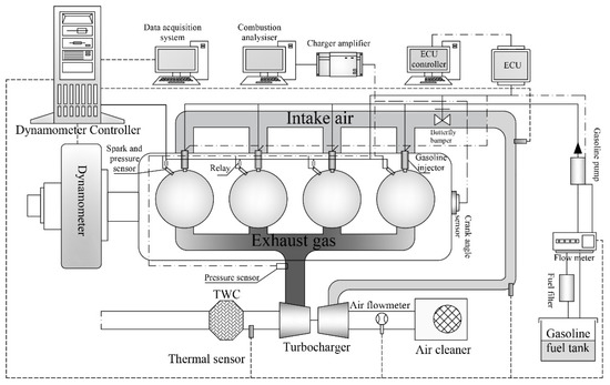
Figure 1.
Schematic of the engine test setup.
2.2. Experimental Methodology
The experiment is divided into two parts. The first part collected the in-cylinder pressure of the four cylinders synchronously. In the second part, the three cylinders’ pressure and exhaust pipe pressure curves were collected synchronously. The one key point of the experiments was to control the ignition timing by cutting off the ignition coil of the electronic ignition system. A manual control method was adopted in this experiment. The schematic diagram of the control circuit is shown in Figure 2. The computer controlled the ignition coil through an electric relay. When the relay was disconnected, the spark plug could not receive the spark signal from the electronic control unit (ECU). With a total of 4 channels, the spark plugs of four cylinder all could be controlled. Since super-knock occurs randomly, engine cycles have to be recorded continuously to capture super-knock cycles. The process of the test, in terms of the maximum amplitude of pressure oscillations (MAPO) time history of the four different cylinders, is shown in Figure 3. Pressure traces of 500 successive engine cycles misfired were recorded. Super-knock and pre-ignition could be distinguished by cylinder pressure. In Figure 3, the ignition coil of cylinder 3 was manually turned on and off. When the ignition coil was turned off, the MAPO was rapidly reduced. After the ignition coil was on, the MAPO returned to its normal value. In order to avoid the contingency of the experimental results, the experiments also were conducted on another engine of the same model to repeat the same ones.
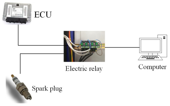
Figure 2.
The schematic diagram of the control circuit.
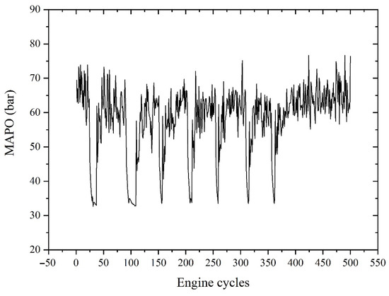
Figure 3.
The maximum amplitude of pressure oscillations (MAPO) time trace for the four different cylinders.
The other key point is to capture abnormal exhaust pressure fluctuations. The installation of exhaust pipe pressure transducer is shown in Figure 4. The water channel was further designed on the mounting base of the transducer, and two sets of cooling water circulation ensured the normal operation of the pressure transducer. The combustion analyzer used in this bench only has four channels. In order to collect cylinder pressure and exhaust pipe pressure synchronously, the exhaust pipe pressure signal will replace the cylinder pressure signal of a certain cylinder during the experiment.
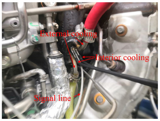
Figure 4.
Exhaust pipe pressure transducer installation.
Standard test procedure was strictly used to enable consistent and statistically reproducible results of all variants of the tests. The test was performed by conducting experiments at low engine speeds (1500–2000 r/min) and wide open throttle (WOT) conditions. In this study, the engine tests were controlled by the original ECU of the engine. The parameters of fuel injection and ignition have been calibrated to the optimal values before these tests. Engine tests were performed after warming the coolant and oil temperatures to 90 ± 3 and 93 ± 3 °C, respectively. A 100% engine load with WOT was kept constant during the tests. The intake air temperature after the Intercooler was maintained at 40 ± 3 °C. To capture the phenomenon of pre-ignition and super-knock under low speed and high load, the experiment selected 6 speeds between 1500 and 2000 r/min with WOT. Under each speed and load, misfire was performed on each of the four cylinders sequentially.
3. Results
This part mainly focuses on abnormal combustion and knock induced by misfires. The observation of the abnormal combustion was mainly made on in-cylinder pressure traces. The analysis of the conclusion is based on the correspondence among the ignition timing and strokes of the four cylinders. The ignition timing was 1-3-4-2. The correspondence among the strokes of the four cylinders is shown as Figure 5.
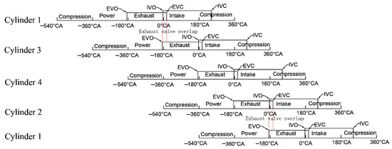
Figure 5.
Correspondence between strokes of four cylinders.
3.1. Abnormal Combustion without Pressure Oscillation n
To explain the effect of misfires on engine combustion, the results at 1500 r/min and WOT were presented. Figure 6 shows the engine test results of four cylinders’ pressure trances under misfires occurring in one cylinder. Figure 6a–d show the four cylinders’ pressure curves under misfires at cylinder 1, cylinder 3, cylinder 4, and cylinder 2, respectively. This sequence is the same as the ignition timing (1-3-4-2). The spark timing at 1500 r/min and WOT was 7.5 °CA before top dead center (BTDC), which was controlled by the original ECU of the engine, and not adjusted to induce knock. Figure 6 indicates one regular pattern: misfire in one cylinder would induce abnormal combustion in the next ignition cylinder corresponding to the misfired cylinder. The Pmax (maximum cylinder pressure) in the next ignition cylinder corresponding to the misfired cylinder increased significantly compared to that in the other two cylinders. In Figure 6b, cylinder 3 misfired, the Pmax of cylinder 4 was larger than the Pmax of cylinder 1 and cylinder 2 by 47.3 bar. In addition, the combustion phase of the next ignition cylinder corresponding to the misfired cylinder advanced significantly compared to that in the other two cylinders. The in-cylinder pressure profile of cylinder 4 significantly deviates from the normal combustion cycle of cylinder 1 and cylinder 2 at −9 °CA BTDC (Figure 6b). However, the in-cylinder pressure profile of cylinders 1 and 2 deviates from the normal motor cycle of cylinder 3 at −18 °CA BTDC.
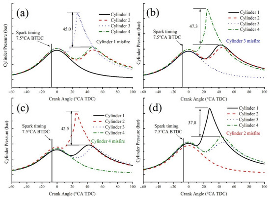
Figure 6.
Abnormal combustion in the next ignition cylinder corresponding to the misfired cylinder: (a) misfired in cylinder 1; (b) misfired in cylinder 3; (c) misfired in cylinder 4; (d) misfired in cylinder 2.
Figure 7 shows the pressure rise rate and heat release rate of the four cylinders when cylinder 3 (Figure 6b) was misfired. Figure 7 shows that the maximum pressure rise rate of cylinder 4 could reach 10 bar/°CA, which was much larger than the pressure rise rate of the other two cylinders. The heat release of cylinder 4 was obviously advanced, and the combustion duration was shortened compared to those of the other cylinders. These phenomena occurred because the thermodynamic state of the unburned gas in cylinder 4 was enhanced when cylinder 3 was misfired.
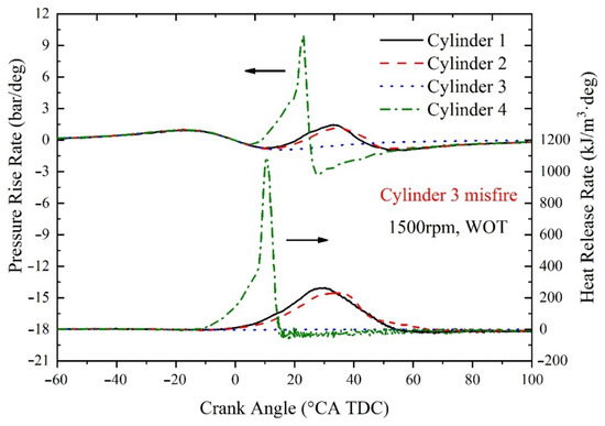
Figure 7.
The pressure rise rate and heat release rate of the four cylinders in Figure 6b.
Figure 8 shows four cylinders’ pressure curves under misfire occurring in one cylinder (1500 r/min, WOT). Figure 8 indicates the other regular pattern: misfire in one cylinder would induce abnormal combustion in the last ignition cylinder corresponding to the misfired cylinder. The Pmax of the last ignition cylinder corresponding to the misfired cylinder increased significantly compared to that of the other two cylinders. In Figure 8c, cylinder 4 was misfired, and the Pmax of cylinder 3 was larger than the Pmax of cylinder 1 and cylinder 2 by 17.2 bar. In addition, the combustion phase of the next ignition cylinder corresponding to the misfired cylinder advanced compared to that of the other two cylinders. The characteristics of pressure rise rate and heat release rate of abnormal combustion were similar to those in Figure 7.
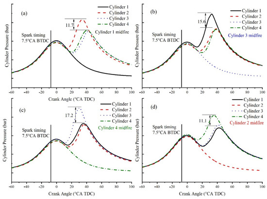
Figure 8.
Abnormal combustion in the last ignition cylinder corresponding to the misfired cylinder: (a) misfired in cylinder 1; (b) misfired in cylinder 3; (c) misfired in cylinder 4; (d) misfired in cylin-der 2.
3.2. Super-Knock in Fired Cylinder
The in-cylinder pressure curves shown in Figure 6 and Figure 8 have no obvious oscillations. However, super-knock was also detected. Figure 9 shows the four cylinders’ pressure curves under misfire occurring in cylinder 2. The corresponding operating point was 2000 r/min and WOT. The spark timing is 4.5 °CA BTDC. In Figure 9, cylinder 2 was misfired, leading to super-knock in cylinder 1, which was the next ignition cylinder corresponding to the misfired cylinder. The Pmax of cylinder 1 increased sharply, accompanied by intense pressure oscillations. Compared with normal combustion, the peak pressure of super-knock could exceed three times higher. A strong detonation wave, which rapidly swept through the pressure transducer, leading to the pressure “discontinuity” of a correspondingly rapid pressure rise of 107.86 bar. This result indicated that misfire in one cylinder will induce super-knock in the next ignition cylinder corresponding to the misfired cylinder. It should be noted that the exhaust stroke of the misfired cylinder corresponds to the power stroke of the knock cylinder. This result indicated that misfire in one cylinder would induce super-knock in the cylinder before starting the power stroke.
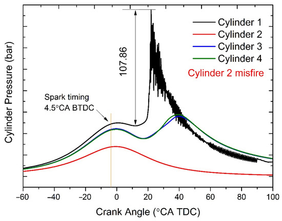
Figure 9.
Super-knock in the next ignition cylinder corresponding to the misfired cylinder.
Figure 10 shows the four cylinders’ pressure curves under misfire occurring in cylinder 2. The corresponding operating point was 2000 r/min and WOT. In Figure 10, cylinder 1 was misfired, leading to super-knock in cylinder 2. The pressure amplitude of cylinder 2 could reach 162.85 bar, accompanied by intense pressure oscillations. This result indicates that misfire in one cylinder would induce super-knock in the last ignition cylinder corresponding to the misfired cylinder. The exhaust stroke of the misfired cylinder corresponds to the intake stroke of the knock cylinder. Misfire in one cylinder would induce super-knock in the cylinder before starting intake stroke. It was worth noting that the compression curves of the four cylinders in Figure 10 were different before ignition, and there is a great non-uniformity in each cylinder. In particular, the compression curve of misfire cylinder is the lowest, which is more obvious in Figure 9. In Figure 9, the TDC pressure of misfire cylinder (Cylinder 2) was 25 bar lower than that of knock cylinder (Cylinder 1).
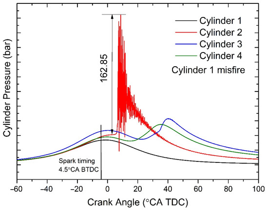
Figure 10.
Super-knock in the last ignition cylinder corresponding to the misfired cylinder.
Figure 11 shows the four cylinders’ pressure curves under misfire occurring in cylinder 1. The corresponding operating point was 2000 r/min and WOT. In Figure 11, cylinder 1 was misfired, leading to super-knock in cylinder 2 and cylinder 3, respectively. The pressure amplitude of cylinder 2 and cylinder 3 could reach 162.30 bar, accompanied by intense pressure oscillations. This result indicated that misfire in one cylinder will simultaneously induce super-knock in the next and last ignition cylinder corresponding to the misfired cylinder. The exhaust stroke of the misfired cylinder corresponds to the power and intake stroke of the knock cylinder. The exhaust stroke of the misfired cylinder corresponds to the power and intake stroke of the knock cylinder. This result indicates that misfire in one cylinder would simultaneously cause knocking occurrence of the cylinders before starting the power and intake stroke, respectively. Similar to Figure 9 and Figure 10, the compression curves of four cylinders in Figure 11 are obviously different, and the compression curve of misfire cylinder is the lowest. The instability of the cylinder pressure curve is mainly due to the occurrence of misfire and super-knock, the combustion state of each cylinder becomes unstable, and there is a great cycle variation. With the occurrence of misfire, the temperature in misfired cylinder decreased, which leaded to the decrease in compression pressure. However, the increase in the temperature in the knock cylinder leads to the increase in the compression pressure, which leads to super-knock. In addition, the mixture of the misfired cylinder entered the exhaust pipe and was ignited, which would produce abnormal pressure fluctuations in the exhaust pipe and enhance exhaust interference.
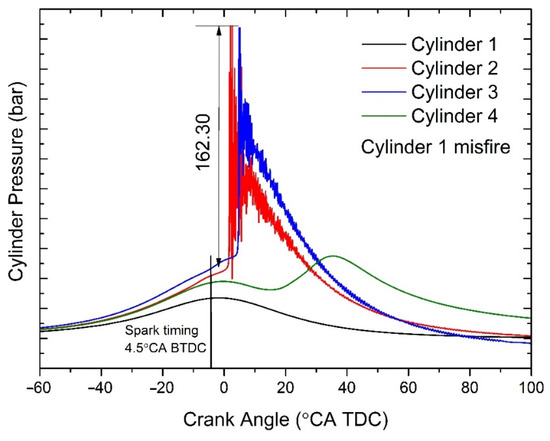
Figure 11.
Super-knock in the next and last ignition cylinder corresponding to the misfired cylinder.
3.3. Super-Knock in Misfired Cylinder
Misfire in one cylinder would induce abnormal combustion not only in the other cylinders, but also in the misfired cylinder itself. Figure 12 shows that the mixture of misfired cylinder was ignited by compression near the TDC and produced a super-knock. The corresponding operating point was 1500 r/min and WOT. As shown in Figure 12, the in-cylinder pressure profile of cylinder 2 deviated from the normal combustion at the TDC. The maximum pressure amplitude could reach 125.74 bar, accompanied by intense pressure oscillations. Detonation should occur in the combustion chamber, which could cause serious damage to the piston. Compressed by the piston, the mixture rapidly reached a state of high temperature and high pressure [21]. Spontaneous ignition occurred at the TDC and, subsequently, the pressure profile deviated from the normal combustion, and jumped to the Pmax value. Different from Figure 9, Figure 10 and Figure 11, the pressure during compression in cylinder 2 with misfire did not differ much from the others. This is because there is no unburned mixture in the exhaust pipe after knock in the misfired cylinder, so there is no exhaust interference. The cycle variation of the engine was improved.
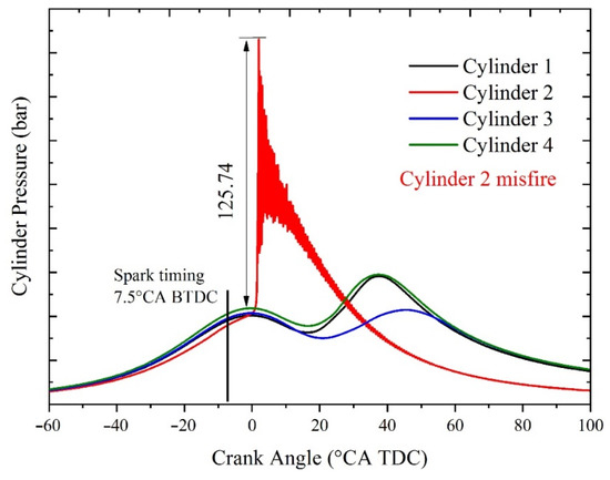
Figure 12.
Super-knock in the misfired cylinder.
Figure 13 shows the phenomenon in which the misfired cylinder was ignited by compression before the spark timing. The corresponding operating point was 1500 r/min and WOT. The in-cylinder pressure profile of cylinder 2 significantly deviated from the normal combustion cycle at 30 °CA BTDC, which indicated a pre-ignition before the normal spark timing of 7.5 CA BTDC. The Pmax was 104.98 bar higher than the compression pressure at TDC, with pressure oscillations. Due to the pre-ignition flame propagation and piston motion, the end-gas was compressed to a state of high temperature and high pressure in a short time; subsequently, spontaneous ignition occurred. The chemical reaction and rapid heat release occur in a short time and within a small space. The heat released promoted pressure wave propagation in the combustion chamber, resulting in a strong pressure oscillation at approximately 20 °CA BTDC. There was no super-knock in Figure 13, so the engine works stably. The cycle variation is small, and the compression pressure curves basically coincide.
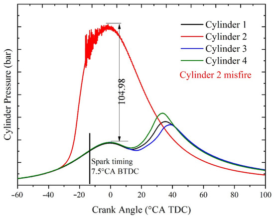
Figure 13.
Pre-ignition in the misfired cylinder.
4. Discussion
The last part revealed the relationship between misfire and super-knock. Each cylinder can interact with each other directly through the exhaust pipe This part further explains the relationship between misfire and super-knock based on the exhaust pipe pressure. Figure 14 shows the exhaust pressure and in-cylinder pressure curves without knocking after misfires in cylinder 1. When cylinder 1 misfired, the exhaust pressure peak generated by cylinder 1 disappeared, and the corresponding crankshaft angle range was from −180 to 0 °CA. However, engine did not always work normally after misfires, and super-knock was captured during the experiments. Take the case of the cylinder 1 as an example, the super-knock caused by misfire could be divided into three situations: (1) the misfire of cylinder 1 would lead to the super-knock in cylinder 3. The ignition timing was 1-3-4-2, so that the exhaust stroke of cylinder 1 corresponds to the power stroke of cylinder 2 (Figure 5); (2) misfire in cylinder 1 would cause super-knock in cylinder 2. The exhaust stroke of cylinder 1 corresponded to the intake stroke of cylinder 2 (Figure 5); (3) super-knock would occur in the misfired cylinder. The above three situations would be discussed based on exhaust pipe pressure and cylinder pressure.
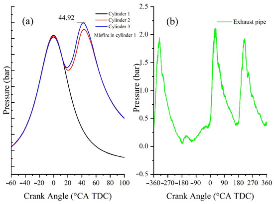
Figure 14.
The exhaust pressure and in-cylinder pressure curves without knocking: (a) the pressure in the exhaust pipe; (b) the pressure in cylinders.
4.1. Knock and Abnormal Exhaust Pipe Pressure
Figure 15 shows three different types of exhaust pressure fluctuations at 1700 r/min and WOT. The exhaust pressure was collected by the fourth channel of the AVL combustion analyzer (the system defaults to the pressure of cylinder 4), and the crankshaft angle range from −180 °CA to 0 °CA was the pressure fluctuation generated by the exhaust pulse of cylinder 1. In general, if cylinder 1 misfired, the mixture in the cylinder was not burned, the exhaust pressure was low, and there was no obvious pressure fluctuation, as shown in Figure 15a. At low speed and full load, the exhaust pipe presented a red hot state with the temperature high to 800 °C before the turbocharger, as shown in Figure 16. Therefore, when cylinder 1 misfired, the unburnt mixture discharged from cylinder might be ignited, or even deflagrated in the exhaust pipe. The pressure fluctuations caused by the combustion of the mixed gas in the exhaust pipe were captured in Figure 15b,c. Especially in Figure 15c, the amplitude and frequency of the pressure oscillations were higher.
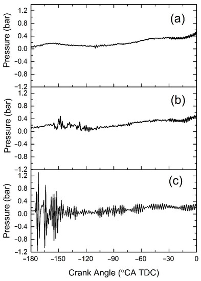
Figure 15.
The different types of exhaust pressure fluctuations: (a) pressure without fluctuation; (b) pressure with slight fluctuation; (c) pressure with severe fluctuation.
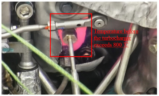
Figure 16.
The exhaust pipe under a red hot state.
The in-cylinder pressure curves of cylinder 3 corresponding to the abovementioned different exhaust pressure oscillations are shown in Figure 17. It can be seen from Figure 17 that when the exhaust pressure did not fluctuate significantly (Figure 15a), the mixture in cylinder 3 burned normally (Figure 17a). When the exhaust pressure fluctuated slightly (Figure 15b), cylinder 3 had a moderate knock (Figure 17b). When the exhaust pressure fluctuated sharply (Figure 15c), super-knock occurred in cylinder 3 (Figure 17c). From the above results, it could be inferred that the knock of cylinder 3 was related to the combustion state of the unburned mixture of cylinder 1 in the exhaust pipe. The sharper the pressure fluctuation, the greater the intensity of knock in cylinder 3. According to the pressure oscillation characteristics of Figure 15c, it could be inferred that a strong pressure wave was generated in the exhaust pipe. According to existing studies [18], its oscillation characteristics were similar to detonation waves, but because the acquisition frequency was low, only 10,200 Hz (1700 r/min, once every 0.1 °CA), no higher pressure peaks were acquired, and the acquisition frequency of detonation waves ordinarily required up to 1 MHz. However, the above results can at least conclude that the abnormal pressure fluctuation in the exhaust pipe was strongly correlated with the occurrence of super-knock in the power cylinder corresponding to the misfired cylinder.
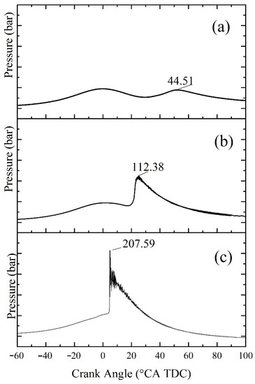
Figure 17.
The in-cylinder pressure curves of cylinder 3: (a) pressure without fluctuation; (b) pressure with slight fluctuation; (c) pressure with severe fluctuation.
4.2. Knock Caused by Blow-By during the Period of Exhaust Valves Overlapped
Misfire in cylinder 1 would also cause super-knock in cylinder 2. Figure 18 shows the pressure curves of the three cylinders and exhaust pipe when cylinder 1 misfired. The corresponding operating conditions were 2000 r/min and WOT. In Figure 8a, cylinder 1 misfired, and cylinder 2 had a super-knock. The Pmax of cylinder 2 could reach 204.3 bar, accompanied by severe pressure oscillations. Compared with normal combustion, the peak pressure of super-knock was more than four times higher. The strong detonation wave quickly swept over the pressure transducer, causing the corresponding cylinder pressure to rise rapidly from 41.4 to 204.3 bar, and the pressure amplitude reached 162.9 bar, causing serious pressure “discontinuity”. This result indicated that misfires in cylinder 1 caused super-knock in cylinder 2. The exhaust stroke of cylinder 1 corresponded to the intake stroke of cylinder 2.
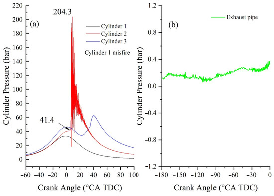
Figure 18.
The exhaust pressure and in-cylinder pressure curves with super-knock in cylinder 2: (a) the pressure in the exhaust pipe; (b) the pressure in cylinders.
It can be seen in Figure 18b that when cylinder 1 misfired and cylinder 2 had a super-knock, the exhaust gas discharged from cylinder 1 did not cause the obvious pressure fluctuation in the exhaust pipe. Therefore, the knocking mechanism of cylinder 2 was different from that of cylinder 3. It could be seen from Figure 5 that when cylinder 1 started to exhaust, the exhaust valve opens. At this time, cylinder 2 was just the starting intake stroke, and its exhaust valve had not been completely closed. Therefore, cylinder 1 and cylinder 2 had an overlap period of the exhaust valve. At this time, the high temperature and high pressure gas in the exhaust pipe rushes into cylinder 2, causing a change in the thermal atmosphere of the mixture in cylinder 2, and then led to super-knocking occurrence in cylinder 2.
4.3. Knock Caused by Residual Gas
A misfire in one cylinder would also cause a super-knock in the misfired cylinder itself. The pressure curve of the misfired cylinder knocking is shown in Figure 19, and the working condition was 1700 r/min and WOT. The misfired cylinder was cylinder 1. In Figure 19a, super-knock occurred in the misfired cylinder. The Pmax could reach 208.34 bar, accompanied by severe pressure oscillations. Since the ignition signal of the first cylinder was cut off, the occurrence of super-knock could only be caused auto-ignition. It could also be seen in Figure 19a that the in-cylinder pressure profile of cylinder 1 significantly deviated from the normal combustion cycle. It could also be seen in Figure 19b that the exhaust gas discharged from cylinder 1 produce an obvious pressure pulse, which also showed that the combustion phenomenon occurred in cylinder 1.
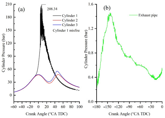
Figure 19.
The exhaust pressure and in-cylinder pressure curves with super-knock in cylinder 1: (a) the pressure in the exhaust pipe; (b) the pressure in cylinders.
There were two main reasons why a misfired cylinder could be ignited by compression. The one was the fuel impingement on the piston pit and the linear portion of the cylinder. As the plug did not spark, the fuel on the wall could not be burned or taken away by strong airflow, resulting in a continuous increase in the wall wetting of the combustion chamber. The other one was the increasing in the amount of high temperature residual gas. The discharged unburned mixture deflagrated in the exhaust pipe and blows high-temperature exhaust gas back to the combustion chamber. According to the existing research, whether the super-knock was induced by the pre-ignition or by spark ignition was due to the spontaneous heat release of the unburned mixture auto-ignition under high temperature and pressure conditions. Consequently, the auto-ignition led to intense pressure oscillation. Then, the interaction between the pressure wave and the flame in the flame preheating zone would also promote the auto-ignition of the mixture, which finally changed the combustion mode from normal combustion to detonation combustion. However, the cumulative effects of fuel and conditions had been ignored. At low speed and high load conditions, misfire was an important factor for super-knock and pre-ignition.
The randomness of super-knock was mainly reflected in the following two aspects: first is the randomness of misfire of spark plug. As the spark plug does not fail suddenly, its loss of function shows a gradual growth. That is to say that misfire will occur when the spark plug starts to lose regular function at the early failure stage. Therefore, misfire occurrence will not take place regularly when it comes out. Misfire itself is random and accidental. The other is the randomness of the combustion of the unburned mixture in exhaust pipe. It can be found from the experimental results that the abnormal pressure fluctuation in the exhaust pipe does not always exist. It also is random and accidental. Finally, a super-knock suppression method is proposed: On-Board Diagnostics (OBD) of engine misfire is added to the engine control strategy. The ion current method has been successfully used to monitor engine misfire [22]. As long as the engine misfire occurs, a strict torque limit is imposed on the engine until the fault is eliminated, such as replacement of the spark plug. At the same time, the use of integrated exhaust pipes should be avoided. It is recommended to use the 4-2 and -1-3 in one common exhaust pipe design or to increase the length of the exhaust pipe and weaken the exhaust pulse interference of each cylinder.
5. Conclusions
A turbocharged GDI engine with an integrated exhaust pipe was used to verify the relationship between misfire and super-knock. The spark plugs of four cylinders were controlled manually. Four piezoelectric pressure transducers were used to monitor the in-cylinder pressure data. In order to further explain the relationship between misfire and super-knock, a piezoelectric pressure transducer was installed at the exhaust pipe to capture abnormal exhaust pressure fluctuations. Based on the interaction between engine cylinders, this study further deepens the effect of the engine misfire on the knock. The results are applicable to turbocharged GDI engines with an 4-1 type integrated exhaust pipe. The main conclusions could be summarized as follows.
- A misfire in one cylinder would induce super-knock in the other cylinders. The maximum pressure amplitude could reach 200 bar, accompanied by intense pressure oscillations. The abnormal combustion usually occurred in the next and last ignition cylinder corresponding to the misfired cylinder.
- The unburned mixture of the misfired cylinder could be ignited by compression near the TDC, and even induce super-knock. At low speed and full load conditions, misfire was an important factor to induce super-knock.
- A misfire in one cylinder could induce pre-ignition. The in-cylinder pressure profile significantly deviated from the normal combustion cycle at 30 °CA BTDC, which indicated a pre-ignition before the normal spark timing of 7.5 CA BTDC. After the occurrence of combustion, the exhaust gas discharged from the misfired cylinder produced an obvious pressure pulse.
- After one cylinder misfired, the unburned mixture would burn in the exhaust pipe to produce pressure waves. The abnormal pressure fluctuation in the exhaust pipe was strongly correlated with the occurrence of super-knock. The sharper the pressure fluctuation, the greater the intensity of knock in the power cylinder.
- Cylinders whose exhaust valve overlapped with the exhaust valve of the misfired cylinder was prone to super-knock. The high temperature and high-pressure gas in the exhaust pipe would rush into the cylinder, and the thermal state in the cylinder would change abruptly, which could easily cause pre-ignition of the homogeneous mixture and even super-knock in the cylinder under intake stroke.
Author Contributions
Conceptualization, C.Y. and S.Z.; methodology, C.Y.; experiment, J.G. and G.Q.; validation, Y.Z. and D.L.; formal analysis, A.Y.; investigation, J.G.; resources, S.Z.; data curation, A.Y.; writing—original draft preparation, J.G.; writing—review and editing, C.Y.; visualization, A.Y.; supervision, C.Y.; project administration, C.Y. and S.Z.; funding acquisition, C.Y. All authors have read and agreed to the published version of the manuscript.
Funding
This paper was supported by the Nature Science Foundation of China (No. 51676134).
Institutional Review Board Statement
Not applicable.
Informed Consent Statement
Not applicable.
Data Availability Statement
Data are contained within the article.
Acknowledgments
The authors acknowledge the financial support from the Nature Science Foundation of China (No. 51676134). The authors wish to express our gratitude to the Technical Center in Dongfeng Motor Cor. Ltd. where experiments were conducted.
Conflicts of Interest
The authors declare no conflict of interest.
Abbreviations
| GDI | gasoline direct injection |
| IC | internal combustion |
| RCM | rapid compression machine |
| DBD | detonation bomb device |
| MoDTC | molybdenum dithiocarbamate |
| ZnDTP | zinc dialkyldithiophosphate |
| LSPI | low speed pre-ignition |
| ECU | electronic control unit |
| MAPO | maximum amplitude of pressure oscillations |
| CA | Crank angle |
| WOT | wide open throttle |
| TDC | top dead center |
| BTDC | before top dead center |
| Pmax | maximum cylinder pressure |
| OBD | On-Board Diagnostics |
References
- Reitz, R.D.; Ogawa, H.; Payri, R.; Fansler, T.; Kokjohn, S.; Moriyoshi, Y.; Agarwal, A.; Arcoumanis, D.; Assanis, D.; Bae, C.; et al. IJER editorial: The future of the internal combustion engine. Int. J. Engine Res. 2020, 21, 3–10. [Google Scholar] [CrossRef]
- Rodríguez-Fernández, J.; Ramos, Á.; Barba, J.; Cárdenas, D.; Delgado, J. Improving fuel economy and engine performance through gasoline fuel octane rating. Energies 2020, 13, 3499. [Google Scholar] [CrossRef]
- Wang, Z.; Liu, H.; Reitz, R.D. Knocking combustion in spark-ignition engines. Prog. Energy Combust. Sci. 2017, 61, 78–112. [Google Scholar] [CrossRef]
- Gao, J.; Yao, A.; Feng, L.; Xu, H.; Yao, C. Experimental investigation on the failures of engine piston subjected to severe knock. SAE Tech. Pap. 2019, 2019. [Google Scholar] [CrossRef]
- Kefalas, A.; Ofner, A.B.; Pirker, G.; Posch, S.; Geiger, B.C.; Wimmer, A. Detection of knocking combustion using the continuous wavelet transformation and a convolutional neural network. Energies 2021, 14, 439. [Google Scholar] [CrossRef]
- Xu, H.; Yao, A.; Yao, C.; Gao, J. Energy convergence of shock waves and its destruction mechanism in cone-roof combustion chambers. Energy Convers. Manag. 2016, 127, 342–354. [Google Scholar] [CrossRef]
- Li, A.; Zheng, Z. Effect of spark ignition timing and water injection temperature on the knock combustion of a GDI engine. Energies 2020, 13, 4931. [Google Scholar] [CrossRef]
- Wei, H.; Shao, A.; Hua, J.; Zhou, L.; Feng, D. Effects of applying a Miller cycle with split injection on engine performance and knock resistance in a downsized gasoline engine. Fuel 2018, 214, 98–107. [Google Scholar] [CrossRef]
- Chen, Y.; Li, L.; Zhang, Q.; Deng, J.; Xie, W.; Zhang, E.; Tong, S. Effects of lubricant additives on auto-ignition under a hot co-flow atmosphere. SAE Tech. Pap. 2017, 1. [Google Scholar] [CrossRef]
- Zahdeh, A.; Rothenberger, P.; Nguyen, W.; Anbarasu, M.; Schmuck-Soldan, S.; Schaefer, J.; Goebel, T. Fundamental approach to investigate pre-ignition in boosted SI engines. SAE Int. J. Engines 2011, 4, 246–273. [Google Scholar] [CrossRef]
- Welling, O.; Collings, N.; Williams, J.; Moss, J. Impact of lubricant composition on low-speed pre-ignition. SAE Tech. Pap. 2014, 1. [Google Scholar] [CrossRef]
- Dahnz, C.; Han, K.-M.; Spicher, U.; Magar, M.; Schiessl, R.; Maas, U. Investigations on pre-ignition in highly supercharged SI engines. SAE Int. J. Engines 2010, 3, 214–224. [Google Scholar] [CrossRef]
- Palaveev, S.; Magar, M.; Kubach, H.; Schiessl, R.; Spicher, U.; Maas, U. Premature flame initiation in a turbocharged DISI engine-Numerical and experimental investigations. SAE Int. J. Engines 2013, 6, 54–66. [Google Scholar] [CrossRef]
- Takeuchi, K.; Fujimoto, K.; Hirano, S.; Yamashita, M. Investigation of engine oil effect on abnormal combustion in turbocharged direct injection-Spark ignition engines. SAE Int. J. Fuels Lubr. 2012, 5, 1017–1024. [Google Scholar] [CrossRef]
- Amann, M.; Mehta, D.; Alger, T. Engine Operating Condition and Gasoline Fuel Composition Effects on Low-Speed Pre-Ignition in High-Performance Spark Ignited Gasoline Engines. SAE Int. J. Engines 2011, 4, 274–285. [Google Scholar] [CrossRef]
- Chapman, E.; Davis, R.S.; Studzinski, W.; Geng, P. Fuel octane and volatility effects on the stochastic pre-ignition behavior of a 2.0L gasoline turbocharged DI engine. SAE Int. J. Fuels Lubr. 2014, 7, 379–389. [Google Scholar] [CrossRef]
- Willand, D.-I.J.; Daniel, I.-M.; Montefrancesco, E.; Geringer, B.; Hofmann, P.; Kieberger, D.-I.M. Limits on downsizing in spark ignition engines due to pre-ignition. MTZ Worldw. 2009, 70, 56–61. [Google Scholar] [CrossRef]
- Kuboyama, T.; Moriyoshi, Y.; Morikawa, K. Visualization and analysis of LSPI mechanism caused by oil droplet, particle and deposit in highly boosted si combustion in low speed range. SAE Int. J. Engines 2015, 8, 529–537. [Google Scholar] [CrossRef]
- Moreno, C.J.; Stenlaas, O.; Tunestal, P. Cylinder pressure based method for in-cycle pilot misfire detection. SAE Tech. Pap. Ser. 2019, 2. [Google Scholar] [CrossRef]
- Tsai, H.; Gao, B.; Chiang, M.; Chen, B. Misfire Diagnostic Strategy for Motorcycles. SAE Tech. Pap. 2013. [Google Scholar] [CrossRef]
- Zhong, L.; Liu, C. Numerical analysis of end-gas autoignition and pressure oscillation in a downsized si engine using large eddy simulation. Energies 2019, 12, 3909. [Google Scholar] [CrossRef]
- Doi, K.; Nakamura, Y.; Hanashi, K.; Hashizume, K. Development of spark plug for ion current misfire detection system. SAE Int. J. Engines 2012, 5, 1387–1393. [Google Scholar] [CrossRef]
Publisher’s Note: MDPI stays neutral with regard to jurisdictional claims in published maps and institutional affiliations. |
© 2021 by the authors. Licensee MDPI, Basel, Switzerland. This article is an open access article distributed under the terms and conditions of the Creative Commons Attribution (CC BY) license (https://creativecommons.org/licenses/by/4.0/).