Article

Aerodynamic Effect of the Gurney Flap on the Front Wing of a F1 Car and Flow Interactions with Car Components

Dipartimento di Ingegneria Meccanica, Energetica, Gestionale e dei Trasporti (DIME), Università degli Studi di Genova, Via Montallegro 1, 16145 Genova, Italy
*
Author to whom correspondence should be addressed.
Energies 2021, 14(8), 2059; https://doi.org/10.3390/en14082059
Submission received: 5 March 2021 / Revised: 29 March 2021 / Accepted: 6 April 2021 / Published: 8 April 2021
(This article belongs to the Special Issue Aerodynamics Modeling)

Abstract

:
The design of a racing car needs several aerodynamic design steps in order to achieve high performance. Each component has an aerodynamic interaction with the others and high performance requires a good match between them. The front wing is undoubtedly one of the main components to determine car performance with a strong interaction with the downstream components. The Gurney Flap (GF) is a small appendix perpendicular to the pressure side of the front wing at the trailing edge that can dramatically improve the front wing performance. In the literature, the performance of a GF on a single profile is well documented, while in this paper the GF mounted on the front wing of a racing car has been investigated and the interactions through the 3D flow structures are discussed. The global drag and downforce performance on the main components of the vehicle have been examined by comparing the cases with and without a GF. The GF increases the downforce by about 24% compared to a limited increase in the drag force. A fluid dynamic analysis has been carried out to understand the physical mechanisms of the flow interaction induced to the other components. The GF, in fact, enhances the ground effect, by redistributing the flow that interacts differently with the other components i.e., the wheel zone.

1. Introduction

In Formula 1 (F1), front wings are one of the main components for the aerodynamic performance of the car. They have been the subject of massive studies that have led to the current configurations after a continuous phase of development since the 1950s. The introduction of CFD techniques, associated with an available computational resources increase, has significantly contributed to the development of ever-increasing aerodynamic performance for the entire vehicle. The changes made to the vehicles over the years have been carried out according to variations that have undergone the various tracks of the world championship. They have become increasingly short and complex over time, and the main objective for cars has moved from reaching their maximum speed to reaching their maximum acceleration. The aerodynamic components designed to have as low drag as possible have been improved to enhance the tire traction during steering and braking, i.e., maximizing the downforce. Typically, the front wing is responsible for 25% of the total downforce generated. The complexity of a front wing has been studied [1] and it is still a crucial issue. The Gurney Flap (GF) is a small supplement mounted perpendicularly to the pressure side of a wing along the trailing edge that brings a series of aerodynamic improvements to the car. In racing vehicles, this component has a height of 1%–5% as the ratio between its height and the chord of the wing. The macroscopic effect of the flap is an increased flow deflection due to both flow recirculation on the pressure side and increased lower base pressure at the trailing edge [2]. This increases the airfoil aerodynamic loading and therefore the downforce. Local effects of the suction side separation bubble at low height from the ground can increase the related drag. Nevertheless, the aerodynamic efficiency (downforce/drag) with a proper flap dimension can increase with respect to baseline airfoil configuration [3]. If the Gurney is mounted on thicker ailerons the drag can be reduced because the vortices break off further downstream on the profile, keeping the boundary layer attached and stable for a wider incidence and ground height range with respect to the baseline case [2]. In several experimental works, the geometrical data of the GF have been optimized according to the application [3,4,5]. Experimental analysis using hot anemometers has shown that the wing without a GF has a wake with less instabilities with respect to the case including it [6,7]. These studies indicate that although the flow downstream of the Gurney satisfies Liebeck’s hypotheses, its instantaneous structure consists of a vortex shedding. To explain how this wake contributes to raising the downforce, these vortices have been investigated on how they form and interact to give a Von Karman’s vortex shedding [8]. It has been shown that for a given incidence and height of the GF, the low pressure acting on the Gurney base remains constant along the surface.
In simple bodies, Rosko [9] noted similar regions of constant low pressure between the separation points due to the vortex shedding that reduces pressure acting on the face downstream of the device in the trailing edge area. Bearman and Trueman [10] hypothesized that this balancing effect is responsible for the increase in the depression area. Bearman [11] also quantified the magnitude of the recirculation zone, introducing the concept of length of formation, defined as the axial distance from the base of the body to the position of maximum. Good and Joubert [12] have shown how for flat plates immersed in a turbulent boundary layer, the maximum pressure measured downstream on the plate increases with the height of the disturbing element. Kennedy and Marsden [13] demonstrated computationally and experimentally that an increase in the load acting on the entire wing is generated, introducing a finite pressure difference at the trailing edge. Aerodynamic studies of the GF have been conducted considering the ground effect [14,15]. The GF has been analyzed and optimized recently in different applications. Tang and Dowell [16] compared the experimental loading of an NACA 0012 airfoil with a static and oscillating trailing edge GF by using an incompressible Navier–Stokes solver. A movable GF on an NACA 4412 airfoil has been studied by Camocardi et al. [17] by investigating the flow structure near the airfoil wake. Lee [18] studied the impact of GFs of different sizes and perforations on an NACA 0012 profile discussing the growth and development of the tip vortex with particle image velocimetry. Recently, Cole et al. [19] studied the effect of different GFs by highlighting that the airfoil shape is also strategic for the aerodynamic performances. Min et al. [20] analyzed the vibration reduction in micro flaps helicopter rotors with a GF. Pastrikakis et al. [21] compared the performance of a helicopter rotor with a GF at different forward flight speeds. A lift enhancement above 10% has been observed by Mohammadi et al. [22] by comparing the clean DU91W(2)250 airfoil. Recently, Woodgate et al. [23] used an inhouse CFD solver to evaluate the implementation of a GF on wings and rotors. Fernandes-Gamiz et al. [24] used CFD RANS models to analyze and design the GF and micro tabs on a S810 airfoil and a DU91(2)250 airfoil; in addition, the proper orthogonal decomposition (POD) has been used to develop a reduced order method. Aramanedia et al. [25] used the same airfoil to show a parametric study on the GF length through RANS models; the Artificial Neural Networks (ANN) have been used to obtain an accurate prediction model of the aerodynamic behavior of the airfoil with a GF.
Extensive aerodynamic analyses on the profile in ground effect have been performed and the simulation of the vortex shedding from the GF has been discussed [26]; a criterion to quantify the wake and the recirculation zone in the vortex shedding mechanism has been developed [27]. The accuracy in numerical prediction of unsteady flows is essential for the vortex shedding mechanisms, but also for other aerodynamic problems like tonal noise [28] or vibro-acoustic stability analysis [29,30]. In this paper the CFD analysis of the aerodynamic performance of the front wing of a Formula 1 car is presented to understand the effects of a GF on the multi-element wing. The flow structures with and without the GF are investigated to also highlight the interaction with downstream car components. Very few studies have been published on the interaction of the Gurney with the other components of a racing car, in order to understand any additional beneficial effects. The first part of the paper examines the global drag and downforce on the main components of the vehicle located between the front wing and the tire. The second part discusses in some detail the differences in the flow structures that occur with or without a GF on the various car components using a set of control planes in the 3D domain. Studies on the aerodynamics of racing car wings using CFD have been published [31,32,33] and the Ansys CFX code, as in the present work, has been used to investigate the ground effect [34]. The CFD model setup is crucial to correctly represent different racing scenarios [35] or to investigate the effect of the wake on the following cars [36]. The 3D model of a real F1 car from the 2000s is used as reference geometry for the analysis. The car model is old, compared to current models, but it is an actual car configuration that participated in F1 championships for years. It can therefore be considered a relevant case in aerodynamic design for the scope of the present paper. It must be evident that a university research group cannot have access to the most recent geometrical designs to publish a research paper. Moreover, any experimental data are kept confidential and not made available to university groups to be published. With the above restrictions, the paper is aimed at the critical analysis of the flow structures around the front wing and the interactions between components (e.g., wheels, struts, etc.) to highlight: (1) the strong aerodynamic interactions between parts, (2) the dramatic effect of a small detail (the Gurney flap) on component performance and aerodynamic interactions. The CFD technology is used as a numerical application tool to investigate and to quantify the above effects. The use of CFD, properly set, is a current design practice for such configurations. The CFD model used has been set up in previous research activities with reference cases where detailed experimental data were available for validation. Only the front part of the car is considered with the rear part modelled with a boat tail to keep the car obstruction to flow close to the front wing. The attention is therefore focused on the GF aerodynamic effects and interactions with the front car components.

2. Geometry and CFD model
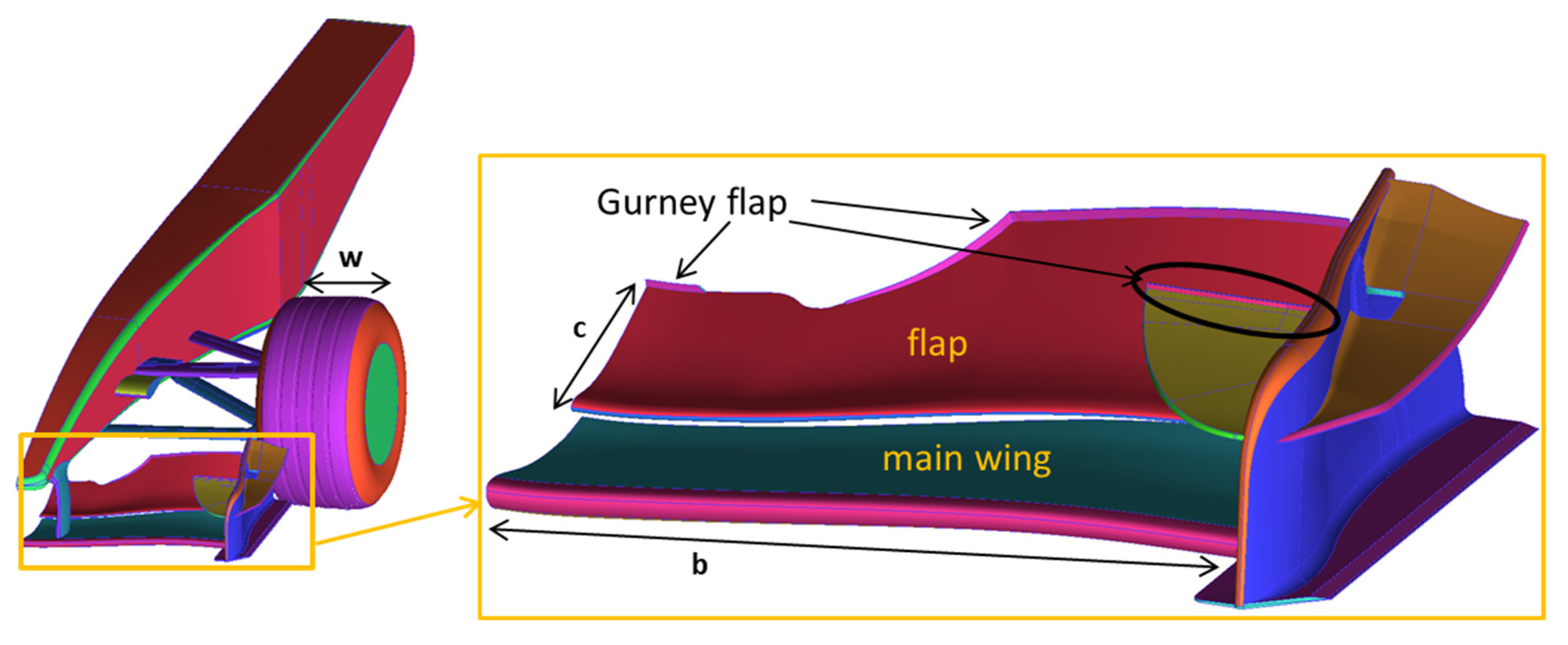
2.1. Application

The geometry used for the analysis is a Formula 1 car of the early 2000s with a front wing composed of: a main wing (main) (c = 0.228 m, b = 0.639 m), a flap (c = 0.182], b = 0.626 m), and two endplates. The endplate facing the exterior of the aileron has c = 0.501 m and b = 0.127 m, while the one facing inwards has c = 0.186 m and b = 0.137 m. The GF is installed perpendicularly to the trailing edge of the flap with the following reference geometry:
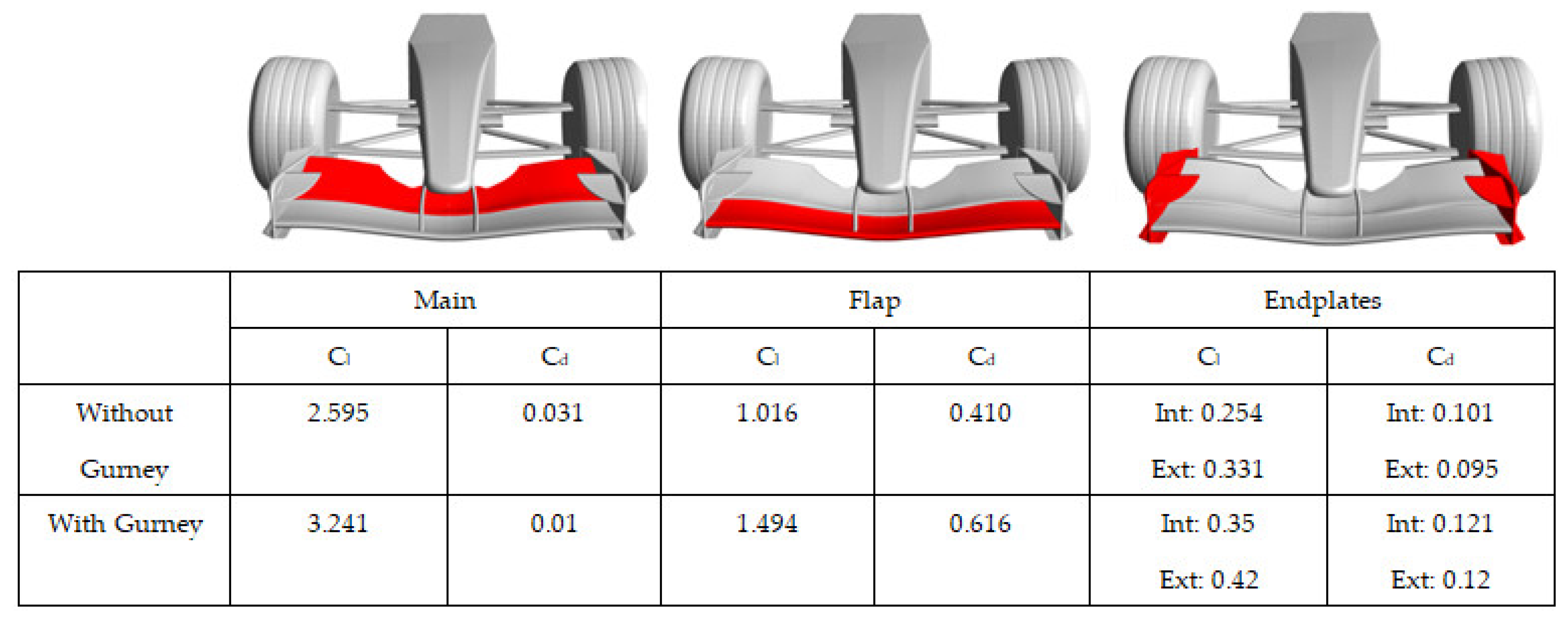
  • Central part with height of 1.35% of the aileron chord and thickness s = 1.75 mm;
  • Lateral part of variable height between 1.8% and 0.36%, with thickness s = 1.9 mm;
  • External part in contact with the endplate with h = 1.8% and s = 1.9 mm;
  • Internal endplate with h = 1% of chord of the complete aileron.
The above front wing is installed in a racing car with a lv = 3.5 m body and maximum width of 0.5 m, with a tire of diameter 620 mm and tread width w = 320 mm. The tire is supported by lower and upper suspensions with an aerodynamic section: the first has c = 77 mm and the second has a variable chord between 85 and 167 mm. A camera is installed with a wing profile with c = 168 mm and b = 100 mm. In Figure 1, the geometry of the vehicle and the front wing with the GF is reported, by highlighting its location.

2.2. Governing Equations
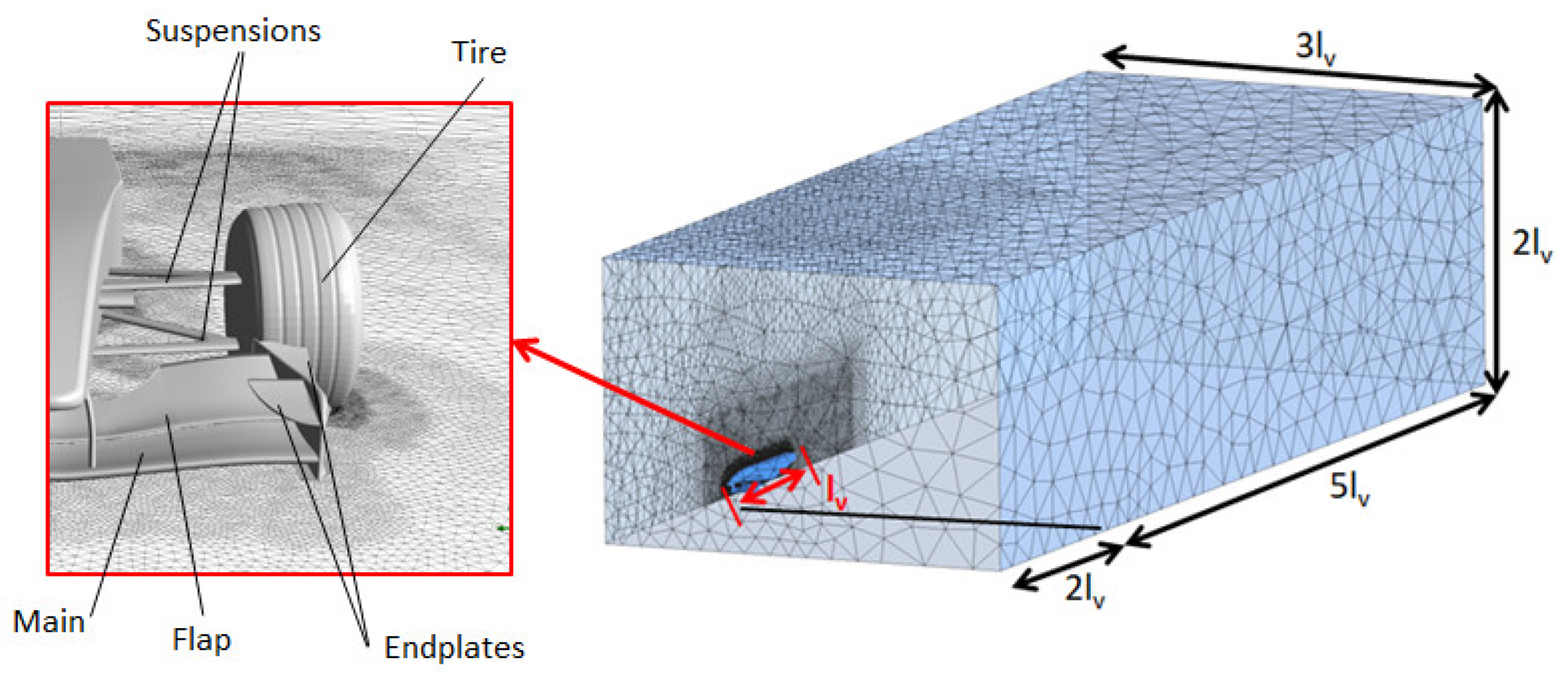
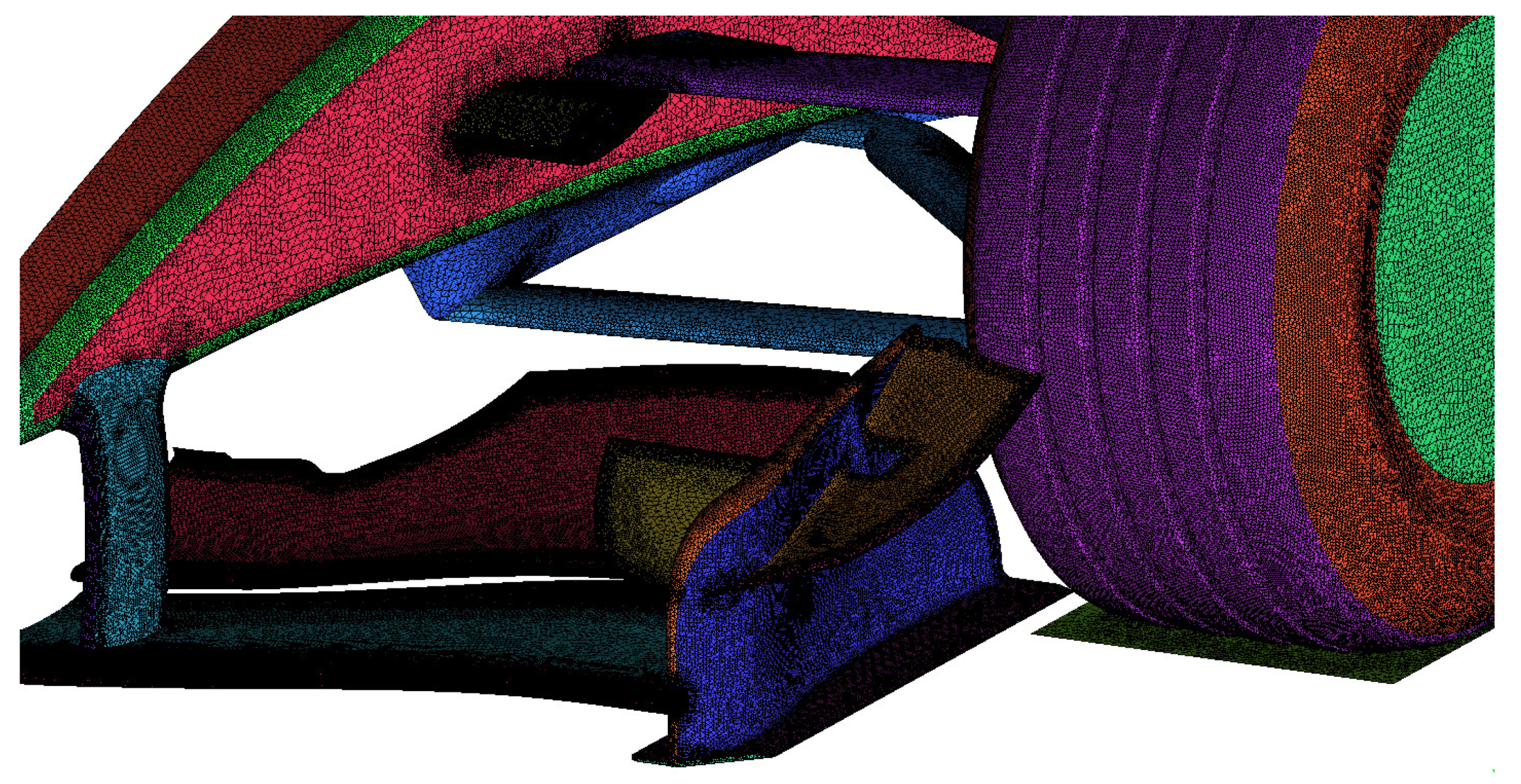
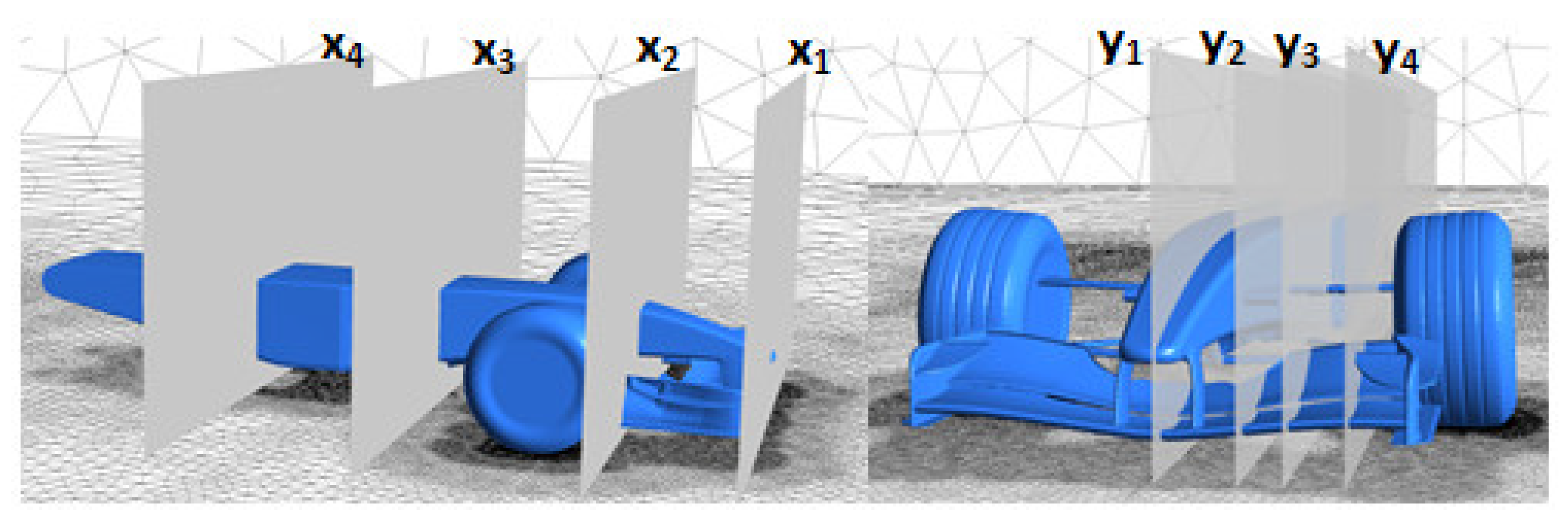
The Reynolds-averaged equation for conservation of mass and momentum form the dynamic flow problem. The turbulence model adopted in the CFD approach is the k-ω SST, in order to solve the boundary layer near the walls; it is based on the Boussinesq’s hypothesis to model the Reynolds stress tensor. This model was developed to combine the accuracy of the k-ω model near the wall and the robustness of the k-ε in the free-stream. It contains some different terms with respect to the standard k-ω formulation. A blending function activates the transformed models k-ω and k-ε depending on the local value of y+, i.e., near or far from the wall [37]. A different formulation for the eddy viscosity and modified constants is introduced. The transport equations are:
t ( ρ k ) + x i ( ρ k u i ) = x j [ Γ k k x j ] + G k Y k + S k
t ( ρ ω ) + x j ( ρ ω u j ) = x j [ Γ ω ω x j ] + G ω Y ω + D ω + S ω
The diffusivity is obtained by the following equations:
Γ k = μ + μ t σ k
Γ ω = μ + μ t σ ω
The eddy viscosity is determined with:
μ t = ρ k ω 1 m a x [ 1 a * , S F 2 a 1 ω ]
The model constants are: σk,1 = 1.176, σω,1 = 2.0, σk,2 = 1.0, σω,2 = 1.168, α1 = 0.31, βi,1 = 0.075, and βi,2 = 0.0828.

2.3. CFD Model

The computational domain for the study of a Formula 1 front wing consists of a rectangular parallelepiped sufficiently extended so that the boundary conditions do not influence the flow structure around the front wing and the front of vehicle. In order to save a considerable amount of computational resources, only one-half of the front wing and the vehicle was modelled, exploiting its axial symmetry. The domain has the following geometrical characteristics: the ground has a surface 3lv × 8lv, while the entire domain has a height of 2lv. In addition, the surface in front of the wing is placed at 2lv, the surface at the outlet is 5lv far. Figure 2 shows the calculation domain and the details of the vehicle geometry. In order to study and compare the case with and without a GF, one model has been cleaned up by the GF from the flap.
The domain has been discretized with an unstructured grid with prism layers near the wall of the vehicle and its components, in order to solve the boundary layer. The size of the first cell has been set to have a y+ close to one. A local refinement is required on the leading edges of the wings and at the trailing edges with the GF, setting a maximum size of 1 mm. The global mesh size consists of about 45 million of cells. In Figure 3, the mesh for the case with a GF is shown, while Figure 4 reports the wall y+ contours along the front wing of the vehicle. The mesh used has been designed to have a high quality; over 90% of cells have a quality higher than 0.5 and with an equi-angle skewness greater than 0.55 and the aspect ratio is higher than 0.6. This mesh strategy with the same local refinement on the wings has been selected after a grid dependency analysis performed in a previous work [26] on the wing in ground effect analyzed in an isolated form with and without a GF. In the previous work [26], the CFD model was validated by comparing the numerical results with detailed experimental data [38,39] at different distances from ground and with different GF heights.
The followings boundary conditions have been set: at the inlet of the domain a uniform velocity of 70 m/s and a turbulence intensity of 5% are fixed, while at the outlet of the domain there is a pressure ambient condition. In the symmetry side, the surface has been fixed as a symmetry condition, while at the surface relative to the ground, a wall no slip condition with the same velocity of the car is set; finally the remaining surfaces of the domain have been set as an inviscid wall. The car surfaces are set as a no slip condition. The flow is considered isothermal and incompressible. All the equations have been solved with second order numerical schemes and steady flow simulations have been set up.

3. Results

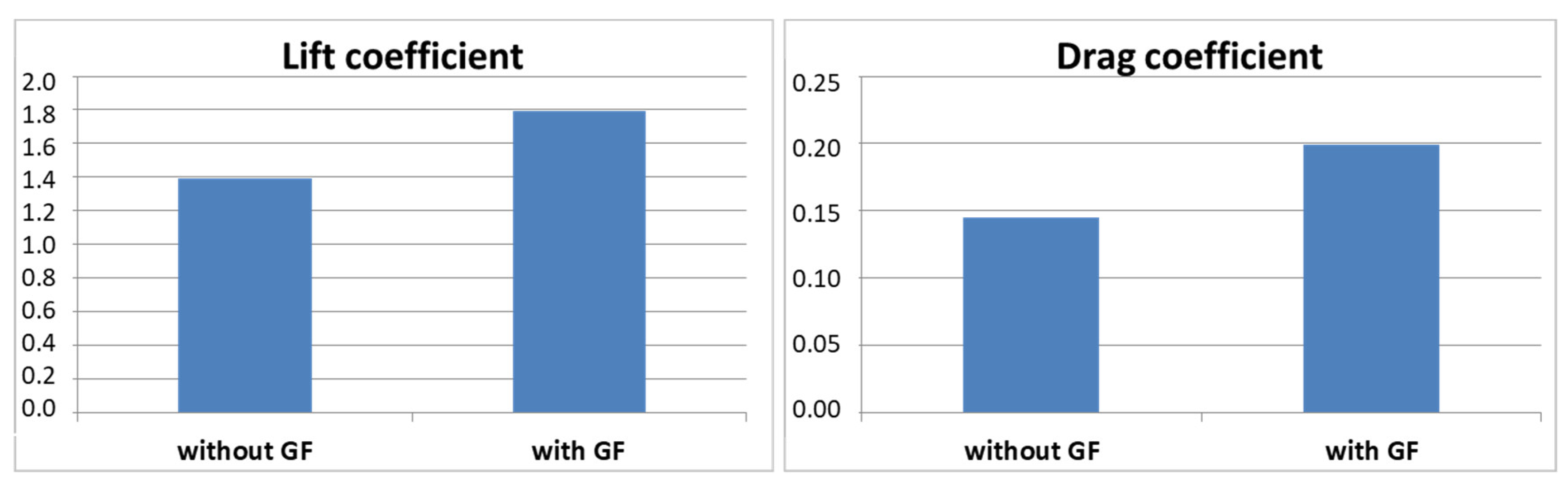
3.1. Global Performance of the Main Components

This section discusses the main differences concerning aerodynamic performance with or without the GF on the front wing. As shown in Figure 5, both the global downforce and drag in the front wing increased with the GF; the lift (downforce) and the drag increased by 23.98% and 28.19%, respectively, while the aerodynamic efficiency E decreased only by 5%.
The lift coefficient Cl and the drag coefficient Cd have been defined as:
C l = L 1 2 ρ A U 2
C d = D R 1 2 ρ A U 2
The aerodynamic efficiency E is defined as:
E = C l C D = L D
This parameter is very important to indicate how much lift (downforce) is obtained with the GF referred to the drag value.
The lift and drag contributions of the individual components were calculated, by measuring, respectively, the vertical and horizontal force components using the commercial post-processing software Ansys CFX-Post. In Figure 6, the contributions of downforce and drag for the main, the flap, and the endplates are shown.
With the GF, a downforce increase of about 30% on the flap and on the endplates and 20% for the main was observed; on the other hand, the drag increased by 33% and 24% on the flap and on the endplates, respectively, but decreased on the main by 67%. The effects on the suspensions (upper and lower), the wheels, and the body of the vehicle are reported in Table 1.
The above components are therefore affected by the GF installation: increase in downforce and drag, with the exception of the wheels where there is a reduction in drag like for the main (see Figure 6).

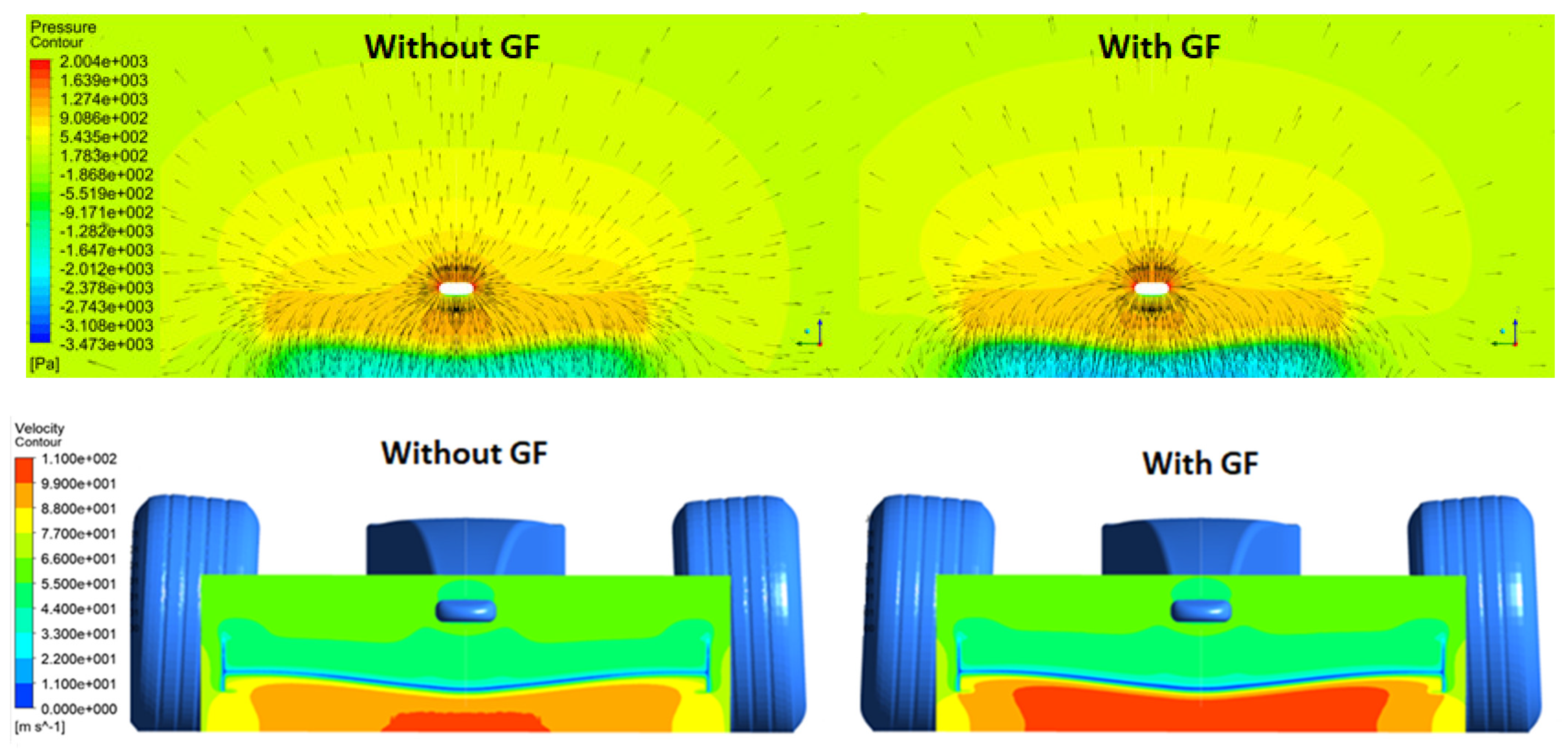
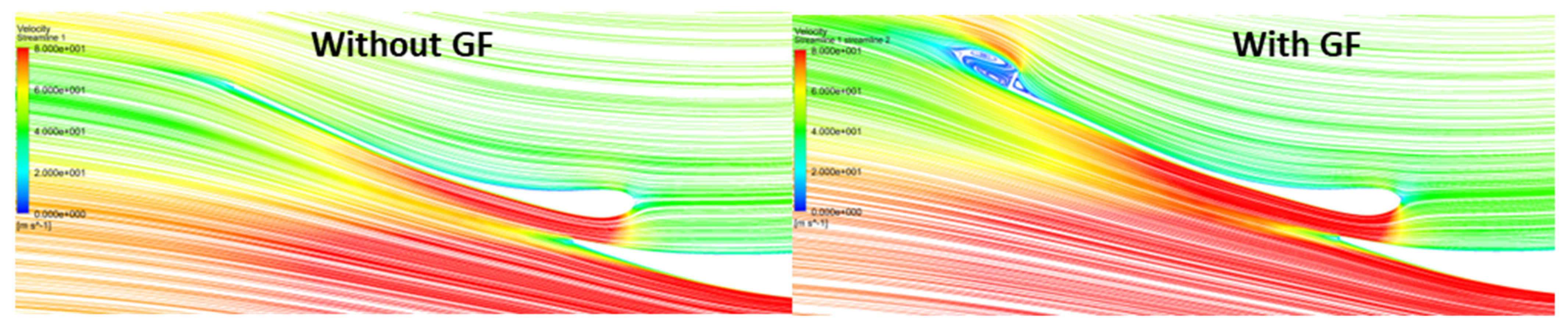
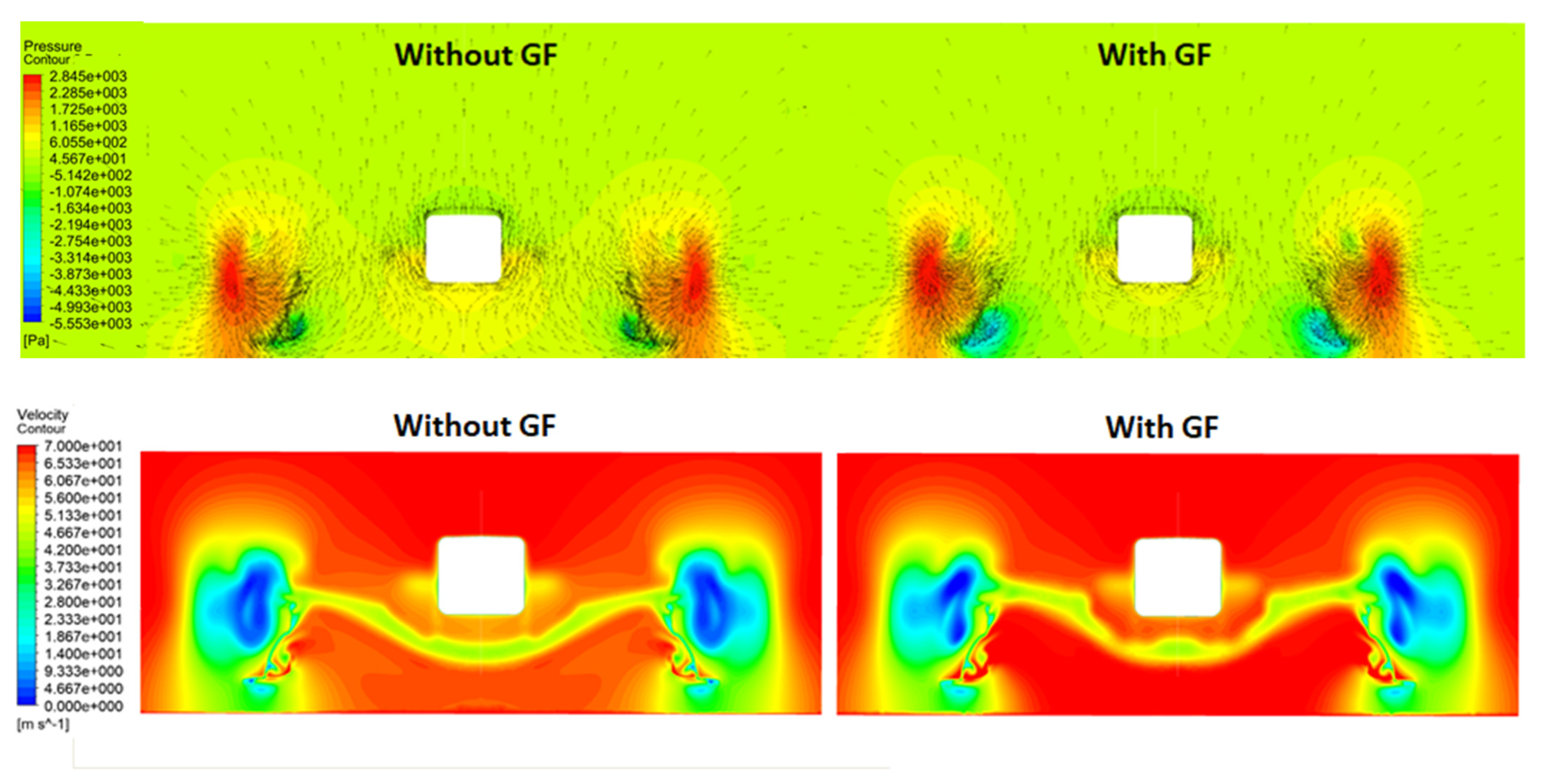
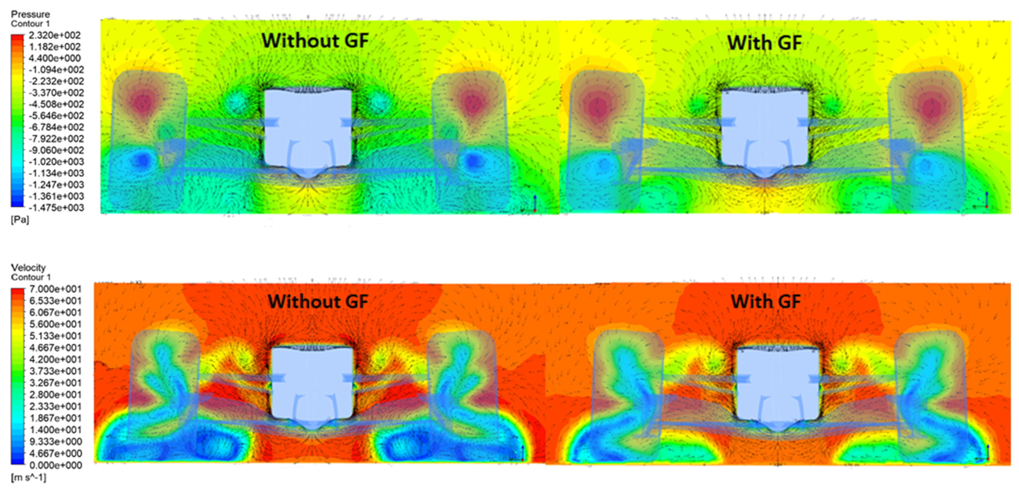
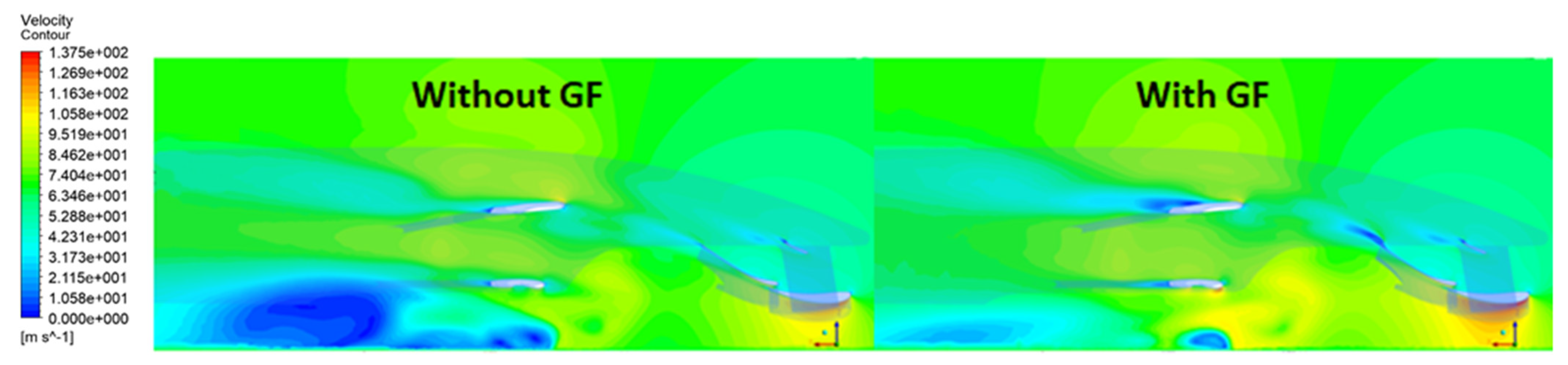
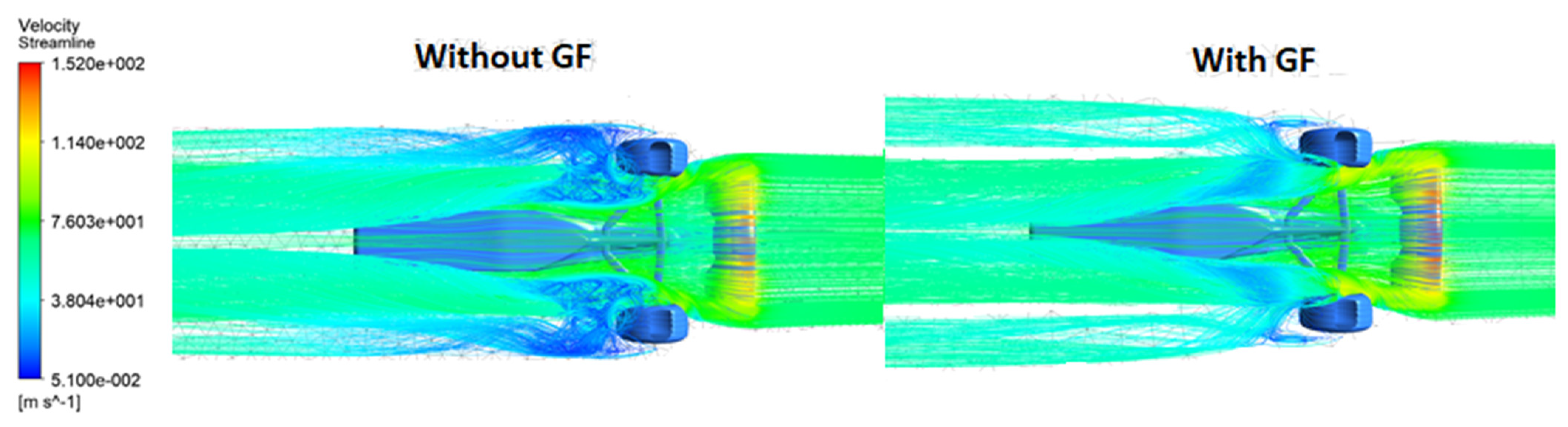
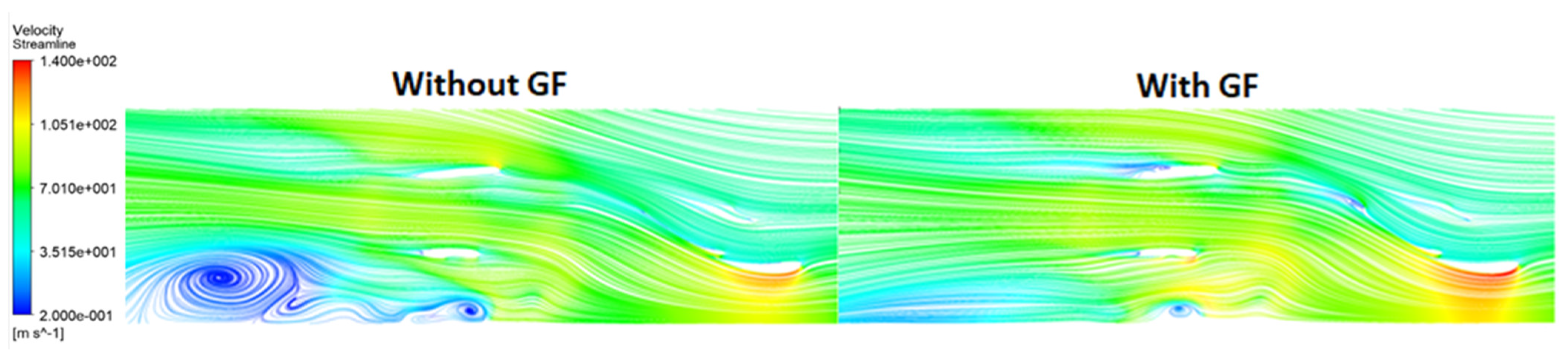
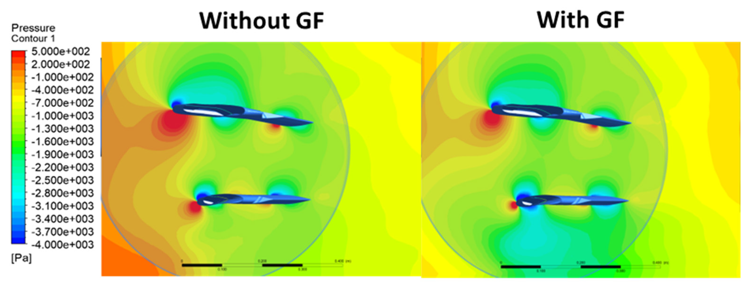
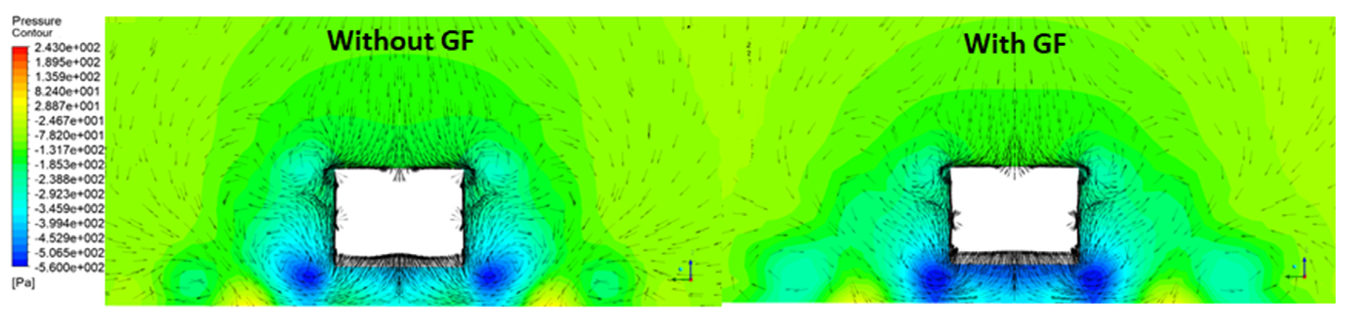
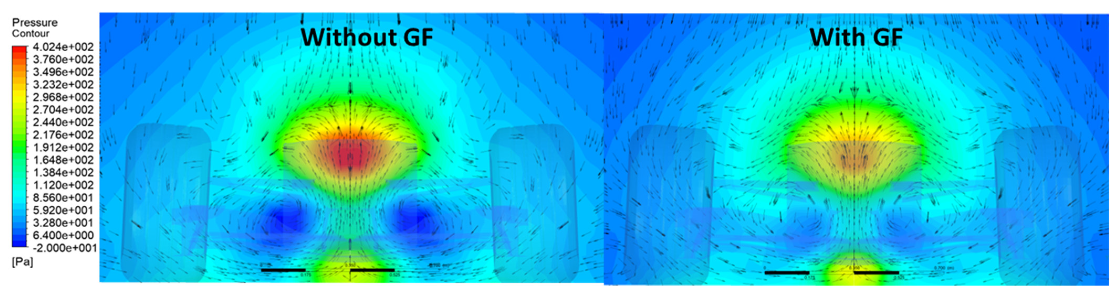
3.2. Fluid-Dynamic Analysis

To understand the main differences on the aerodynamic performance of the vehicle and its components, a fluid dynamic analysis was carried out on a set of control planes, as shown in Figure 7.
On plane x1, Figure 8, the comparison of the contours for pressure and velocity, with and without a GF, are plotted to understand the reason for the downforce increase and drag reduction on the main wing with a GF.
A large area of low pressure (high velocity) under the main wing is evident with the GF installed that enhances the ground effect. The flow is affected by the presence of the GF and redistributed below the main wing and towards the endplate, as seen by the velocity vectors. The velocity increase along the suction side gives a smaller wake on the main wing as seen in Figure 9, where the streamlines on the y2 plane are plotted. This is the main reason for the drag reduction on the main wing with a GF installed. The same figure also shows the typical flow structure with recirculating flows upstream and downstream the GF on the flap element of the wing.
The same fluid dynamics analysis was performed on the x2 plane to understand the increase in drag and in downforce on the endplate. Pressure and velocity contours are reported in Figure 10.
The velocity vectors have an evident upwash direction in the wing central area, while laterally the flow interacts with the tire and tends to be deviated in all directions. By comparing the case with and without a GF, an evident low-pressure region is located in the lower part of the endplate facing the car in the case with a GF. Without the GF, the above depression area is negligible. With the GF, the flow is accelerated under the base of the endplate causing the low pressure zones. In these regions, due to the redistribution of the flow, higher velocities are observed downstream from the endplate. The flow rate, and consequently the axial velocity, is distributed more evenly over the car and in the bottom area of the main wing and the flap. Therefore, the flow passes through the channels generated by the base of the endplate, with higher velocities giving rise to a relevant ground effect on the endplate. However, at the endplate exit the pressure remains lower, generating a larger wake with higher drag. Even in the wheel area, the flow differs between the case with and without a GF. With the GF, the fluid being deflected, carries out a greater path causing a greater kinetic energy loss. For this reason, near the tread, in the low region, there are no marked depression areas. The same set of contours on plane x3 are shown in Figure 11 to understand the phenomena related to the performance on suspensions and wheel.
The baseline case without a GF has three distinct swirling directions affected by the presence of the wheel. The first is at the top of the wheel (where high pressures and separations are generated on the tread and on the rubber sides). The second is due to the turbulences created by the wheel (where low pressure is reached). The third is due to the flow that externally and internally bypasses the wheel (influenced by the flow exiting the endplate). In the area between the bottom of the car and the wheel, on the back of the lower suspension, a low-pressure zone is created with upward motion. With the GF, the main difference concerns the flow pattern below the front wing near the ground; it is more swirling with a smaller extension of the low-pressure zones, while the velocities remain higher. In this region, there is a different interaction between the mainstream and the suspension with a greater turbulence than with a GF. This different interaction is displayed on the y4 plane of Figure 12 with the velocity contours.
A large recirculation bubble is generated below the lower suspension without the GF; the incoming flow on the suspension, induced by the GF, has a correct incidence with the suspension rod that strongly reduces its wake. The radically different flow structure that forms in the tires wake, under the suspensions, can be observed in Figure 13 using the streamlines visualization.
Figure 14 shows the streamlines pattern on a transversal plane close to the endplates (plane y4) where the flow without a GF (left) is slower close to ground and gives rise to a large recirculation area due to interaction with the tire. The configuration with the GF, as previously discussed, has higher velocity close to ground and the above recirculation area is absent; the flow is deflected upward with a positive interaction with the suspensions, as previously discussed. However, in this last case, the wake of the car is wider (streamlines deflection) thus giving more overall drag, but also beneficial effects on the tire, as previously claimed.
In Figure 15 the pressure contours on the y3 plane are shown. They highlight that a large low-pressure area is generated on the nose of the connector with the GF and a reduction of the high-pressure zone below the suspension. These combined effects give more downforce with the GF installed.
The pressure contours on the x4 plane are shown in Figure 16 to discuss the various aerodynamic effects acting on the other parts of the vehicle.
Low-pressure zones around the car and under the body are generated by vortices that develop from the ground at the corners of the body sections. These vortices and their low pressure are useful to both feed the cooling sections (main radiator and brakes) and to generate additional downforce. In the case with the GF, the low-pressure regions are more extended below the body, resulting in more downforce. However, the drag generated at the rear of the vehicle is higher. This can be argued from the analysis of Figure 17, where the pressure contours on a plane downstream of the vehicle are shown. The flow structure in the wake with a GF has a larger and stronger recirculating zone with low pressure that increases the pressure drag of the vehicle.
The pressure coefficient distributions on the wing and flap sections at planes y1, y2, and y3 are reported in Figure 18. From these graphs, it is clear that the aerodynamic loads are higher with the GF installed, giving more downforce from both wing and flap.

4. Conclusions

The results of detailed CFD analysis on a vehicle configuration representative of an F1 car have been used to investigate the effects of GF installation on the flow structure and on component performances. It can be observed that the addition of this small device has a dramatic effect on the overall flow structure around the car. The flow structure from the front wing affected by the GF will interact with the other car components with evident aerodynamic performance changes with respect to the baseline configuration. The overall front wing downforce increases of almost 24%, while the drag force increase is 28%. The contribution of this paper is to highlight the effects that the GF can have on the car components, to give an interpretation of the aerodynamic performance from the flow structures, and to stress the strong aerodynamic interaction between components from the addition of the GF. The main difference with a GF, consists in a large area of low pressure under the main wing that enhances the ground effect, which causes a redistribution of the flow in the other components: a flow acceleration under the base of the endplate and a better interaction with the wheel group. On the contrary, without a GF large recirculation bubbles on the lower part of the vehicle are detected. It has been highlighted that the correct dimensioning and installation of the GF can increase the aerodynamic downforce from different car components, with an increase in the aerodynamic efficiency compared to baseline. The CFD technology is an essential tool to support the design and aerodynamic tuning of the car.

Author Contributions

M.B., C.C., D.M. have equally contributed to the concept of the research activity, the setup of the model, the discussion of the results, and the writing of the paper. All authors have read and agreed to the published version of the manuscript.

Funding

No external findings have to be cited.

Institutional Review Board Statement

Not applicable.

Informed Consent Statement

Not applicable.

Data Availability Statement

Not applicable.

Conflicts of Interest

The authors declare no conflict of interest.

Nomenclature

AArea
bWing span
cWing chord
CdDrag coefficient
ClLift coefficient (downforce)
CpPressure coefficient
dDiameter
DRDrag coefficient
EAerodynamic efficiency
hHeight of Gurney flap (percentage of the airfoil chord)
kTurbulent kinetic energy
LLift (downforce)
lvVehicle length
pStatic pressure
sThickness
uVelocity
u’Axial local velocity
U Velocity at the domain inlet
wWidth
y+Non dimensional boundary layer distance from wall
µDynamic viscosity
ρDensity
ωSpecific rate of dissipation

Acronyms

extExternal
GFGurney Flap
infInferior
intInternal
supSuperior

References

  1. Roberts, L.S.; Correia, J.; Finnis, M.V.; Knowles, K. Aerodynamic characteristic of a wing-and-flap configuration in ground effect and yaw. Proc. IMechE Part D J. Automob. Eng. 2016, 230, 841–854. [Google Scholar] [CrossRef]
  2. Zerihan, J.; Zhang, X. Aerodynamics of Gurney Flaps on a Wing in Ground Effect. AIAA J. 2001, 39, 772–780. [Google Scholar] [CrossRef]
  3. Jeffrey, D.; Zhang, X.; Hurst, D.W. Aerodynamics of Gurney Flaps on a Single-Element High-Lift Wing. J. Aircr. 2000, 37, 295–301. [Google Scholar] [CrossRef]
  4. Liebek, R.H. Design of Subsonic Airfoils for High Lift. J. Aircr. 1978, 15, 547–561. [Google Scholar] [CrossRef]
  5. Myose, R.; Papadakis, M.; Heron, I. Gurney Flap Experiments on Airfoils, Wings and Reflection Plane Model. J. Aircr. 1998, 35, 206–211. [Google Scholar] [CrossRef]
  6. Coles, D.; Wadcock, A.J. Flying-Hot-Wire Study of Flow Past an NACA 4412 Airfoil at Maximum Lift. AIAA J. 1979, 17, 321–329. [Google Scholar] [CrossRef]
  7. Thompson, B.E.; Whitelae, J.H. Trailing-Edge Region of Airfoils. J. Aircr. 1989, 26, 225–234. [Google Scholar] [CrossRef]
  8. Gerrard, J.H. The mechanics of the formation region of vortices behind bluff bodies. J. Fluid Mech. 1966, 25, 401–413. [Google Scholar] [CrossRef]
  9. Roshko, A. On the Drag and Shedding Frequency of Two-Dimensional Bluff Bodies; NACA TN 3169; National Advisory Committee Aeronautics: Moffett Field, CA, USA, 1954.
  10. Bearman, P.W.; Trueman, D.M. An Investigation of the Flow around Rectangular Cylinders. Aeronaut. J. 1972, 23, 229–237. [Google Scholar] [CrossRef]
  11. Bearman, P.W. Investigation of the flow behind a two-dimensional model with a blunt trailing edge and fitted with splitter plates. J. Fluids Mech. 1965, 21, 241–255. [Google Scholar] [CrossRef]
  12. Good, M.C.; Joubert, P.N. The form drag of two-dimensional bluff-plates immersed in turbulent boundary layers. J. Fluid Mech. 1968, 31, 547–582. [Google Scholar] [CrossRef]
  13. Kennedy, J.L.; Marsden, D.J. The development of High Lift, Single-component Airfoil Sections. Aeronaut. J. 1979, 30, 343–359. [Google Scholar] [CrossRef]
  14. Zhang, X.; Zerihan, J. Off-Surface Aerodynamic Measurements of a Wing in Ground Effect. J. Aircr. 2003, 40, 716–725. [Google Scholar] [CrossRef]
  15. Zhang, X.; Zerihan, J. Aerodynamics of a Double-Element Wing in Ground Effect. AIAA J. 2003, 41, 1007–1016. [Google Scholar] [CrossRef] [Green Version]
  16. Tang, D.; Dowell, E.H. Aerodynamic loading for an airfoil with an oscillating gurney flap. J. Aircr. 2007, 44, 1245–1257. [Google Scholar] [CrossRef]
  17. Camocardi, M.; Marañon, J.; Delnero, J.; Colman, J. Experimental study of a naca 4412 airfoil with movable gurney flap. In Proceedings of the 49th AIAA Aerospace Sciences Meeting including the New Horizons Forum and Aerospace Exposition, Orlando, FL, USA, 4–7 January 2011. [Google Scholar]
  18. Lee, T. Piv study of near-field tip vortex behind perforated gurney flaps. Exp. Fluids 2010, 50, 351–361. [Google Scholar] [CrossRef]
  19. Cole, J.A.; Vieira, B.A.O.; Coder, J.G.; Premi, A.; Maughmer, M.D. Experimental Investigation into the Effect of Gurney Flaps on Various Airfoils. J. Aircr. 2013, 50, 1287–1294. [Google Scholar] [CrossRef]
  20. Min, B.Y.; Sankar, L.N.; Rajmohan, N.; Prasad, J.V.R. Computational Investigation of Gurney Flap Effects on Rotors in Forward Flight. J. Aircr. 2009, 46, 1957–1964. [Google Scholar] [CrossRef]
  21. Pastrikakis, V.A.; Steijl, R.; Barakos, G.N. Effect of active Gurney flaps on overall helicopter flight envelope. Aeronaut. J. 2016, 120, 1230–1261. [Google Scholar] [CrossRef] [Green Version]
  22. Mohammadi, M.; Doosttalab, A.; Doosttalab, M. The effect of various gurney flaps shapes on the performace of wind turbine airfoils. In Proceedings of the ASME Early Career Technical Conference, Atlanta, GA, USA, 2–3 November 2012. [Google Scholar]
  23. Woodgate, M.A.; Pastrikakis, V.A.; Barakos, G.N. Rotor Computations with Active Gurney Flaps. Adv. Fluid-Struct. Interact. 2016, 133, 133–166. [Google Scholar]
  24. Fernandez-Gamiz, U.; Gomez-Mármol, M.; Chacón-Rebollo, T. Computational Modeling of Gurney Flaps and Microtabs by POD Method. Energies 2018, 11, 2091. [Google Scholar] [CrossRef] [Green Version]
  25. Aramendia, I.; Fernandez-Gamiz, U.; Zulueta, E.; Saenz-Aguirre, A.; Teso-Fz-Betoño, D. Parametric Study of a Gurney Flap Implementation in a DU91W(2)250 Airfoil. Energies 2019, 12, 294. [Google Scholar] [CrossRef] [Green Version]
  26. Cravero, C. Aerodynamic performance prediction of a profile in ground effect with and without a Gurney flap. ASME J. Fluids Eng. 2017, 139. [Google Scholar] [CrossRef]
  27. Cravero, C.; Marogna, N.; Marsano, D. A Numerical Study of correlation between recirculation length and shedding frequency in vortex shedding phenomena. WSEAS Trans. Fluid Mech. 2021, 16, 48–62. [Google Scholar] [CrossRef]
  28. Cravero, C.; Marsano, D. Numerical prediction of tonal noise in centrifugal blowers. In Proceedings of the Turbo Expo 2018: Turbomachinery Technical Conference & Exposition, Oslo, Norway, 11–15 June 2018. [Google Scholar]
  29. Niccolini Marmont Du Haut Champ, C.A.; Silvestri, P. Experimental and numerical vibro-acoustic investigation on a trimmed car door to analyze slamming event. Appl. Acoust. 2020, 166, 107380. [Google Scholar] [CrossRef]
  30. Guerrero, J.E.; Pacioselli, C.; Pralits, J.O.; Negrello, F.; Silvestri, P.; Lucifredi, A.; Bottaro, A. Preliminary design of a small-sized flapping UAV: I. Aerodynamic performance and static longitudinal stability. Meccanica 2016, 51, 1343–1367. [Google Scholar] [CrossRef]
  31. Huminic, A.; Chiru, A. On CFD Investigations of Vehicle Aerodynamics with Rotating Wheels’ Simulation; Technical Paper 2006-01-08-04; SAE World Congress: Detroit, MI, USA, 2006. [Google Scholar]
  32. Wang, Y.N.; Tseng, C.Y.; Huang, Y.L.; Leong, J.C. Investigation of 2004 Ferrari Formula One Race Car Wing Effects. In Proceedings of the International Symposium on Computer, Communication, Control and Automation, Tainan, Taiwan, 5–7 May 2010; pp. 85–88. [Google Scholar]
  33. Kieffer, W.; Moujares, S.; Armbya, N. CFD study of section characteristics of Formula Mazda race car wings. Math. Comput. Model. 2006, 43, 1275–1287. [Google Scholar] [CrossRef]
  34. Huminic, A.; Huminic, G. CFD Investigations of an Open-Wheel Race Car. In Proceedings of the 4th European Automotive Simulation Conference, Munich, Germany, 6–7 July 2009. [Google Scholar]
  35. Soso, M.D.; Wilson, P.A. Aerodynamic of a wing in ground effect in generic racing car wake flows. Proc. IMechE Part D J. Automob. Eng. 2006, 220, 1–13. [Google Scholar] [CrossRef]
  36. Newbon, J.; Dominy, R.; Sims-Williams, D. CFD Investigation of the Effect of the Salient Flow Features in the Wake of a Generic Open-Wheel Race Car. SAE Int. J. Passeng. Cars-Mech. Syst. 2015, 8, 217–232. [Google Scholar] [CrossRef] [Green Version]
  37. ANSYS Inc. Ansys CFX Theory Guide; v.17; ANSYS Inc.: Canonsburg, PA, USA, 2016. [Google Scholar]
  38. Zerihan, J.; Zhang, X. Aerodynamics of a Single Element Wing in Ground Effect. J. Aircr. 2000, 37, 1058. [Google Scholar] [CrossRef]
  39. Zerihan, J. An Investigation into the Aerodynamics of Wings in Ground Effect. Ph.D. Thesis, University of Southampton, Southampton, UK, 2001; 236p. [Google Scholar]
Figure 1. Geometry of the model and front wing with GF details.
Energies 14 02059 g001
Figure 2. Computational domain and geometry detail of the vehicle simulated.
Energies 14 02059 g002
Figure 3. Detail of the calculation grid of the aileron’s vehicle.
Energies 14 02059 g003
Figure 4. Wall y+ contours on the aileron’s vehicle.
Energies 14 02059 g004
Figure 5. Lift and drag coefficients of the complete aileron with and without GF.
Energies 14 02059 g005
Figure 6. Cl and Cd performance comparison on main, flap, and endplates.
Energies 14 02059 g006
Figure 7. Characteristic plans considered for the fluid dynamics analysis in the x, y direction.
Energies 14 02059 g007
Figure 8. Comparison on the x1 plane of distributions between the case with (right) and without GF (left): (above) pressure contours with velocity vectors, (below) velocity contours.
Energies 14 02059 g008
Figure 9. Comparison on the y2 plane of streamline between the case without (left) and with (right) GF.
Energies 14 02059 g009
Figure 10. Comparison on the x2 plane of distributions between the case with and without GF: (above) pressure contours with velocity vectors, (below) velocity contours.
Energies 14 02059 g010
Figure 11. Comparison on the on the x3 plane of distributions between the case with and without GF: (above) pressure contours with velocity vectors, (below) velocity contours, and vectors.
Energies 14 02059 g011
Figure 12. Comparison on the y4 plane of velocity contours between the case with and without GF.
Energies 14 02059 g012
Figure 13. Comparison of the streamlines below the vehicle between the case with and without GF.
Energies 14 02059 g013
Figure 14. Comparison on the y4 plane of the streamlines. Without (left) and with (right) GF.
Energies 14 02059 g014
Figure 15. Comparison on the y3 plane of pressure contours. Case without (left) and with (right) GF.
Energies 14 02059 g015
Figure 16. Comparison on the x4 plane of pressure contours with velocity vectors. Case without (left) and with (right) GF.
Energies 14 02059 g016
Figure 17. Comparison of pressure contours with velocity vectors on a downstream plane. Case with (left) and without (right) GF.
Energies 14 02059 g017
Figure 18. Pressure coefficients on wing (upper) and flap (lower) sections on plans y1, y2 and y3 with (red lines) and without (blue lines) GF.
Energies 14 02059 g018
Table 1. Percentage variation of aerodynamic forces on suspension, tire and vehicle body.
SuspensionsTireVehicle Body
DownforceDragDownforceDragDownforceDrag
Upper: +22.7Upper: +2.6+37.9−25.8+62.9+48.7
Lower: +62.8Lower: +57.4
Publisher’s Note: MDPI stays neutral with regard to jurisdictional claims in published maps and institutional affiliations.

