1. Introduction
There is a great commotion in the automotive industry: hybrid-electric vehicles (HEV) and full-electric vehicles (EV) are becoming more and more competitive to internal-combustion engine vehicles. New proposals are continuously presented on the market. These suggestions are characterized by lower emissions, cost and better capability of the batteries. The latter improving power electronics and electro-mechanical devices. Big effort is carried out to reach some specific objectives:
optimization of the traction electric motor drive,
development of electronic devices to help the driver,
performing of strategies typical in robotic applications to make the vehicle autonomous.
The focus of the research will be on the first issue, that is, the analysis, design and optimization of an innovative electric motor drive for automotive applications [
1,
2]. The HEV seems to be a passing step. The direction is the design and the optimization of the full EV. Up to some years ago, the development of full EVs was converged on small-size vehicles, mainly electric bicycles and scooters. Now, the market is directed to EVs of larger size: primarily cars but also buses and trucks. In this trend, the Automotive Companies are looking for different solutions for the power-train.
The trend of the Automotive Companies is to increase the electric motor features. The maximum torque and the maximum power is more and more increasing [
3,
4]. This means that particular attention is paid to optimize the machine geometry, considering both electromagnetic and mechanical performance and thermal capability [
5]. Actually, the technology is mainly oriented to synchronous permanent magnet (PM) machines [
6,
7,
8]. and the interior permanent magnet (IPM) motor is the most promising candidate [
9,
10]. It is adopted in more than 80% of the vehicles thanks to its torque and power density higher than other motor types [
11].
The most of the motors adopt rare earth PMs: NdFeB, assisted by Dysprosium to increase the temperature stability. The PMs are inset in the rotor iron, achieving the so called IPM rotor. This solution exhibits advantages and drawbacks [
6,
12]. The motor exhibits an high torque density and a quite high constant-power speed range. However, the use of rare earth PMs represents a high cost for the motor. Therefore, Automotive Companies are interested to evaluate alternative solutions, without giving up the actual performance.
To the aim of evaluate alternative to the IPM motors, this paper deals with the analysis of an Hybrid-Excitation Permanent-Magnet (HEPM) machine. This machine is characterized by a rotor including both PMs and excitation coils. Various configurations of this kind of machines are described in [
13,
14]. The excitation coils in the HEPM machine allow the rotor flux to be regulated during the machine operations.
Hereafter the focus is given to the performance of the motor during the Flux-Weakening (FW) operations [
15,
16,
17]. It is evaluated the potentials of reducing the rotor flux, to get a better behavior at high speeds. It will be shown that the HEPM motor can exhibit a higher torque during FW operation with respect the IPM motor, and it can reach a wide speed range. Even if the control of this machine [
18] is slightly more complex, the HEPM motor represents a good option for machines operating in FW region.
The structure of the paper is as follows: At first the normalised system is presented, which allows to obtain general results. Based of this system, all the combinations of the motor parameters are identified to satisfy the same nominal operating point. Based on these parameters the capabilty during FW operations are computed. The performance of IPM and HEPM motors are compared. To the aim of validate the theoretical results, a configuration is analysed in detail by means of finite element method.
2. Desired Performance
The HEPM motor is considered to be an alternative of the IPM motor. The advantage of this solution is that it allows a higher torque at the highest speed. The basic idea is described in the following. During FW operations the rotor winding is fed by a demagnetizing current so as to reduce the rotor flux. As a consequence the voltage limit becomes less imperative and the HEPM motor exhibits a torque higher than the IPM motor in a wide speed range.
For the sake of generality the motor parameters are given in normalized values. In this way the results presented hereafter can be extended to motors of any rated power. Moreover, the use of normalized values allows an easy comparison between different types of motor drive. Therefore, nominal voltage
, the nominal torque
, and the nominal electrical speed
, at the end of the constant torque region, are defined as base quantities. The other base quantities, as the motor parameters and nominal current, are fixed by means of the power balance:
Then,
The normalized quantities are expressed as reported in
Table 1. Let’s note that
is the actual operating angular frequency (or electrical speed) that is related to the synchronous mechanical speed
by
where
p is the number of pole pairs.
By using a synchronous
reference frame with the
d-axis coincident with the PM flux direction, and neglecting the stator resistance, the voltage equations are given by:
The two components of the stator flux linkages can be expressed as a function of PM flux linkage and current components, as follows:
The rated motor current and voltage are limited by the inverter capabilities. Hereafter, the rated motor quantities are assumed to be exactly coincident with the inverter limits, and are indicated as
and
. By considering the inverter capabilities, the current limit is given by:
In the same way, the voltage limit can be expressed as:
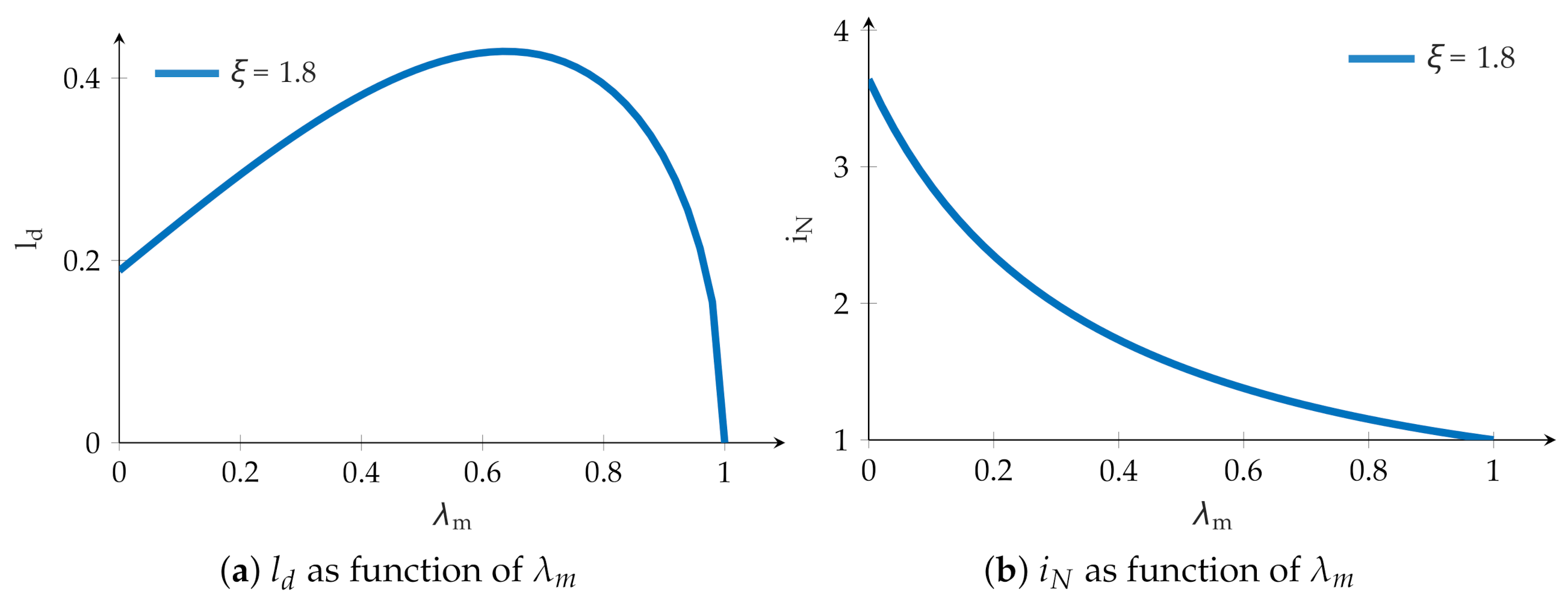
If
, as shown in
Figure 1a, there are three operating regions of interest. Below the base speed
the motor is operating along the Maximum Torque per Ampere (MTPA) trajectory, so as to minimize the stator current for a given torque. At speed higher than
the FW operation occurs: at first the current vector moves on the current limit circle. Finally, when the Maximum Torque per Voltage (MPTV) trajectory is reached, the current vector moves on such a trajectory.
It is worth mentioning that the Maximum Torque Per Voltage (MTPV) trajectory exists only if
. Otherwise, if
then MTPV trajectory does not exist and a there is maximum speed
as shown in
Figure 1b.
2.1. Base Operating Point
By means of the normalization described above, it is possible to obtain all the combinations of PM flux linkage
,
d- and
q-axis inductance
and
(or, alternatively, saliency ratio
) and nominal current
satisfying the nominal values
,
,
, that is, the nominal operating point, described in
Table 1. These combinations are shown graphically as a function of
and
in
Figure 2a,b. In these figures
has been fixed while the
d-axis inductance
and the nominal current
are drawn as a function of the PM flux linkage
.
Figure 2a,b show that the direct inductance
and the current limit
depend on the choice of the PM flux linkage
and the saliency ratio
in order to satisfy the conditions
at
and
.
Since any combination yields the same torque and power in the nominal operating point (
,
and
) then, the solutions with a higher PM flux are preferable since they allow to reduce the nominal current
of the motor, as it is evident in
Figure 2b. To improve the motor torque density (high torque in small dimensions), the motors are often chosen with a high PM flux linkage, which are solutions characterized by
. Therefore, it yields that the electromagnetic PM torque component dominant compared to the reluctance one.
2.2. Flux-Weakening Operating Point
At this point, the combinations of the parameters computed above are used to predict the motor performance during the operations at speeds higher than the base speed , that is, during FW operations.
Some examples are shown in
Figure 3a Two speeds have been chosen where the maximum FW torque
is computed, they are
and
. According to the combinations achieved in
Figure 2a,b, the torque
is a function of
, with
.
Figure 3a highlights that the motors characterized by a high
exhibit zero torque at that speeds. Their maximum speed is lower than
(
) or even than
(
). In other words, the motors characterized by a high
are not able to reach high speeds. At speeds higher than the base speed, both torque and power decrease quickly with the speed.
This is illustrated in
Figure 3b using the dotted (red) curve. An IPM motor is considered characterized by a high PM flux linkage. The choice of its parameters has been done to satisfy the nominal point (
at
, with
). The FW operations are limited to the maximum speed
, where there is a zero torque.
2.3. Effect of a Variable Rotor Flux
To improve the motor performance at the higher speeds the rotor flux should be reduced as a function of the speed. Using a classical IPM motor this is not possible, since the PMs inset in the rotor produce a fixed flux. On the contrary, if a HEPM motor is used, the rotor flux can be modified during the motor operation. In this case, the flux linkage due to the rotor is referred to as and it considers the contribution of both PMs and the excitation winding.
It is worth noticing that the normalised parameters of the HEPM motor can be achieved from
Figure 2, only considering the maximum flux
as variable, instead of the PM flux
.
During FW operations the rotor flux
is regulated so as to achieve a torque as high as possible according to that speed
. It is possible to determine the optimal rotor flux as a function of the normalized parameters of the motor, as:
Such a
is the flux linkage that maximized the torque for any speed
. The relationship between
and
, shows that
reduces when the speed
increases. The transition from “full flux” to “reduced flux” starts when
becomes lower than
. Thus, the flux linkage obtained by (
9) is valid only when it results to be lower than the nominal flux linkage.
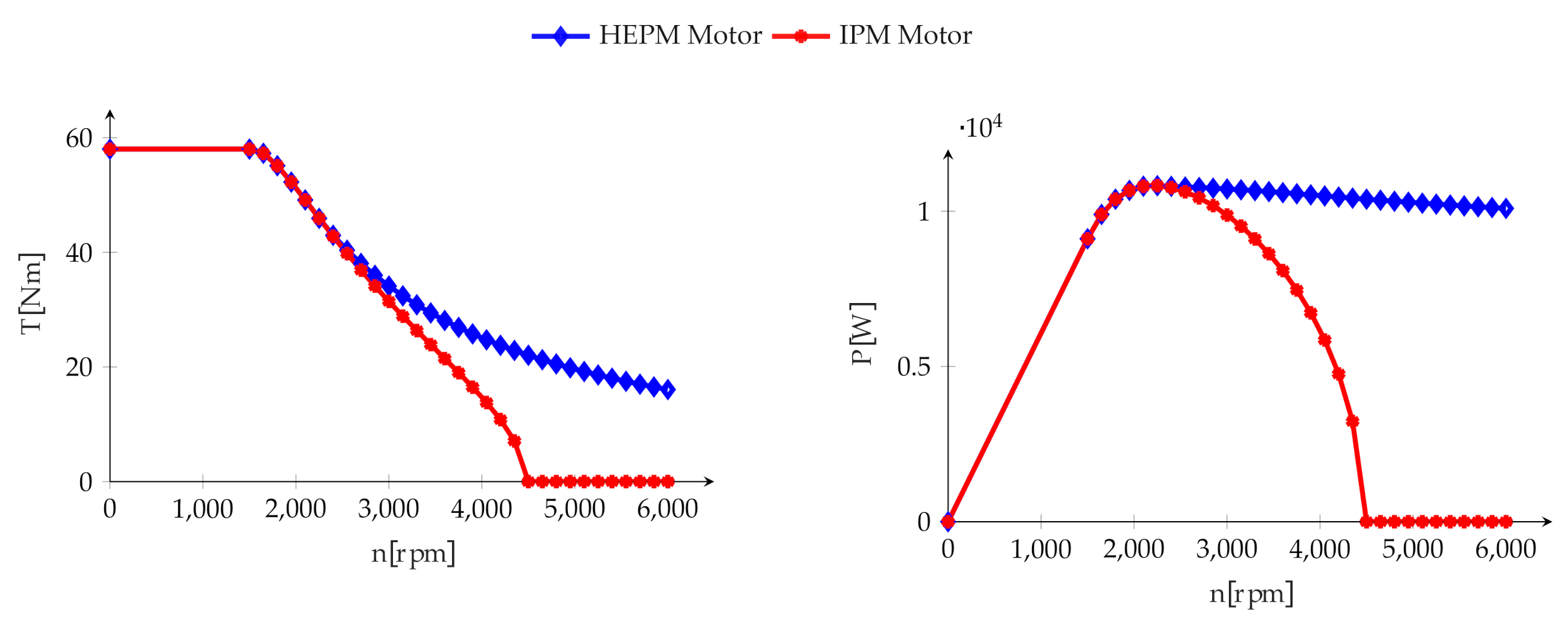
Figure 3b shows, using (blue) diamond curve, the behavior of the torque versus speed of the HEPM machine with the same parameters and nominal current of the IPM motor. With this choice the performance is the same at the nominal point (
at
), it is the same for speeds slightly higher, but it is completely different at the higher speeds, where the reduction of the rotor flux is applied. Such a rotor flux reduction starts when the two curves depart each other.
2.4. Polar Diagrams of an IPM Motor
Referring to IPM motors, with different PM flux linkage
,
Figure 4 shows the voltage limit ellipses, current limit circle and the MTPV trajectory at various speeds
. These diagrams focus on the working operating point defined in each caption. The motor is capable to operate at that given speed only if there is an intersection area between the (red) current limit circle and the (blue) voltage limit ellipse. Black dashed lines refer to the MTPV trajectories.
Figure 4a,d refer to a synchronous reluctance motor, i.e., to a machine without PM. The torque is only given by a reluctance component. As expected,
Figure 4a,d show the possibility of the motor to work at high speed, since the voltage limit ellipse is always inside the current limit circle.
Figure 4b,e show a motor with PM flux linkage equal to
, that is a moderate rotor flux linkage. With higher PM flux linkage, the nominal current is lower, as also evident from the size of the circles. In this case the motor can work at high speed, since there is always the intersection between the voltage limit ellipse and the current limit circle. At speed
the the current vector is on the current circle. At speed
the current vector is along the MTPV trajectory,
Figure 4e.
Figure 4c,f refer to a motor with a high PM flux linkage, and a low nominal current, as shown by the small size of the current circle. With the high flux the operating speed reduces.
Figure 4c,f show that there is no intersection between voltage limit ellipse and the current limit circle, neither at
nor at
. Then, there is not any feasible operation point.
The IPM motor chosen for the following comparison is characterized by a quite high PM flux linkage.
3. Finite Element Analysis of IPM and HEPM Motor Performances
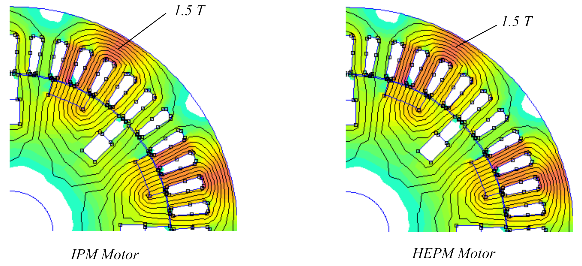
To validate the results presented above, a detailed comparison is carried out between the IPM motor and the HEPM motor. For the sake of comparison their geometry is almost the same, as shown in
Figure 5. The IPM motor rotor contains only PMs, while the HEPM motor rotor includes PMs and excitation coils, thus the rotor flux is due to two components PMs and rotor current.
The choice of the rotor flux is important to get a high torque density: high PM flux is chosen to minimize the machine volume, to maximize the torque, to limit the stator currents so as to reduce the Joule losses and to increase the efficiency of the machine. However, as shown above, the drawback of such a choice is a low FW capability.
In the following example, a high PM flux IPM motor is considered. By means of a Finite Element Analysis (FEA), it will be confirmed that this motor exhibits a low FW capability, as shown in p.u. in
Figure 3a.
3.1. Analysis of the IPM Motor
The stator geometry of the IPM motor under consideration is defined by
Table 2. The stator lamination is M235-35A. The rotor is equipped with UH-38 NdFeB PMs, whose parameters are defined in
Table 2, corresponding to 20
. The PMs are buried in the rotor lamination.
In order to compare the IPM motor performance with the HEPM motor ones, rotor slots have been designed to include the excitation winding, but they are empty in the IPM rotor. As far as the stator winding is concerned, a three-phase embricate, double-layer winding with star connection is adopted.
The performance at the base point and in FW operations have been analyzed using FE keeping particular attention to the speed limit.
3.2. Analysis of HEPM Motor Performance
As shown in
Figure 5, the HEPM motor is considered with the same geometry of the IPM motor: the stator and rotor dimensions remain the same, the PMs remains the same and only the rotor winding is added. In this way it is possible to compare two identical configurations the same saliency ratio
and the same
axis inductances. The quadrature inductance
is
and and the direct inductance
is
. The data of the excitation winding are reported in
Table 3.
Thanks to this choice both motors exhibit the same torque at the nominal speed, that is
. The analysis is carried out assuming that the control system of the HEPM motor regulates the excitation current so as to decrease the rotor flux in FW operations following the relationship given in (
9). Let us remember that
(when lower than
) is the optimal rotor flux linkage to maximize the torque at any given speed above the base speed.
3.3. IPM and HEPM Motor Comparison
Figure 6 shows the current components resulting from the simulation as a function of the speed. In the HEPM motor there is no current in the rotor until 2500 rpm. Above that speed the reduction of the rotor flux of the motor begins. From that speed the HEPM motor exhibits higher torque and power, as shown in
Figure 7. It is worth noticing that the
q-axis current of HEPM motor,
, is higher than the corresponding
q-axis current of IPM motor.
Controlling both stator and rotor currents to maximize the torque versus speed characteristic, the flux developed by the excitation current is opposite to the PM flux. However, there is no demagnetization problem because the path of the flux due to the rotor current is in parallel with the path of the PM flux. Since the iron permeance is much higher than the PM permeance, the flux produced by the excitation coils does not flow through the PM.
Figure 8 and
Figure 9 show the flux density of the IPM motor and the HEPM motor. They show that the flux density in the PM is the same at base speed, when there is not flux reduction, and at the speed four times the base speed, when the reduction of rotor flux is maximum.
As a consequence of the demagnetizing rotor current, the average rotor flux density in the HEPM motor is lower than rotor flux density in the IPM motor. On the contrary, even if the flux density remains almost the same for both the motor configurations, it is slightly higher in the HEPM stator.
The torque of the IPM motor decreases down to zero at 4350 rpm. This behavior shows that the motor is not able to work above that speeds, while the HEPM motor still exhibits a considerable torque.
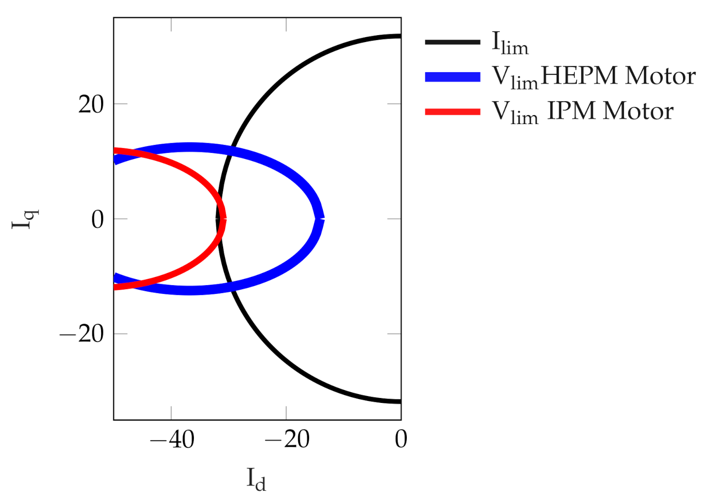
It is interesting to analyse the motor behavior in the
plane.
Figure 10 shows the IPM and HEPM motor voltage limit ellipses at n = 4350 rpm and the current limit circles. At this speed, it is evident that the voltage limit ellipse of the HEPM motor results modified by the rotor flux reduction. It is worth noticing that without any flux reduction the voltage ellipse is the same since the machines are identical. Due to the rotor flux reduction, the center of the HEPM voltage limit ellipse moves on the right hand side. In addition, the size of the ellipse increases. As a consequence, the operating stator current vector of the HEPM motor is closer to the nominal operating point, with a consequent torque higher than that of the IPM motor. Thus, it is verified that the electromechanical torque increases considerably at high speed varying simultaneously both stator and rotor currents.
3.4. Rotor Losses and Efficiency
The overall losses, , are analyzed. Adding the rotor winding to modulate the rotor flux, there are additional rotor Joule losses during the motor operations.
The efficiency increases slightly, remaining higher than 90% in a wide speed range as shown in
Figure 11a. However, the output power of the HEPM also increases compared to the IPM machine. Comparing the total losses to the developed power, as shown in
Figure 11b, the percentage losses result to be lower in HEPM motor.
Figure 11c shows the absolute losses and
Figure 11d shows the motor losses components of the HEPM motor where
are the stator Joule losses,
the iron losses,
the rotor joule losses.
constant,
increase with speed,
increase but are quite low. The excitation rotor winding introduce losses, so the absolute losses increase. In
Figure 11d, the IPM motor exhibits lower losses than HEPM motor due to higher flux density.
The stator joule losses
are constant along all the FW operation of the HEPM motor. It is also interesting to observe that, in addition to the rotor Joule losses
, the HEPM motor works with a current vector closer to the MTPA trajectory, so that the stator iron losses increase as well. The iron losses
are higher when the reduction of rotor flux starts. A zoom of the joule rotor losses
is shown in
Figure 12a.
3.5. Overload Torque Operations
Finally, it is worth noticing that the excitation rotor current has been supplied only to decrease the rotor flux, that is to produce a flux in opposite direction to the PM flux. However, the excitation rotor current could be also supplied to produce a flux supporting the PM flux, increasing the torque at low speed, e.g., in overload conditions.
Figure 12b shows how the torque of the HEPM motor could be increased at low speeds by increasing the rotor flux by means of the rotor current.
4. Conclusions
This paper highlights the advantages of a motor with HEPM rotor compared to standard IPM motor. Both motors are designed with the same dimensions and exhibiting same performance at base speed. HEPM motor shown an overall efficiency of values from 93 to 88%. In this range of efficiency the maximum speed reached is 4 time the base point speed. This is a wide advantage compared to the IPM motor that has a lower speed range (3 times the base point operation) with an efficiency range from 93 to 78%. HEPM Motor achieved a power higher than IPM motor during the FW operation, that started from a speed of 2250 rpm with a power of and end to 6000 rpm with a power of .
The advantage of the HEPM machine is highlighted during the FW operating conditions. The reduction of the rotor flux allows the motor to exhibit higher torque during FW operations even if there are additional Joule losses in the rotor winding. Despite these losses in the rotor winding, the overall efficiency is higher. Moreover, the motor works with higher torque and a better efficiency in a wider operating speed range. The possibility of overload in the machine increases the average torque from 58 · to 76 · ; this is interesting in traction motor drive where the overload conditions are often reached.


