1. Introduction
The constant increase in transportation routes between mine shafts and workplaces is a consequence of the development of mines. This situation has been observed for several decades. Rapid industrial development at the turn of the 19th and 20th centuries caused significant growth in coal demand because coal was the principal energy resource at that time. Growing coal production enforced mine expansion and, in turn, lengthening of roadways [
1,
2,
3]. At present, the main cause of longer distances in coal mines is the need to develop mining areas that are distant from shafts in exploited deposits [
4].
Numerous means of transport have been developed to improve communication between distant excavations and mine shafts [
5,
6,
7]. Due to the many advantages of railway, this form of transport became the most popular in underground mines, particularly combustion and electric floor railways. These have now been replaced in most cases by friction-gear-driven suspended railways, on which mine transport systems are based. Suspended railways are efficient and relatively fast means of transport. Thus, transportation of people and materials is safe and easy, even in the case of distant mine areas [
5,
8].
However, despite the development of means of mass transport, the problem of individual transport remains unsolved [
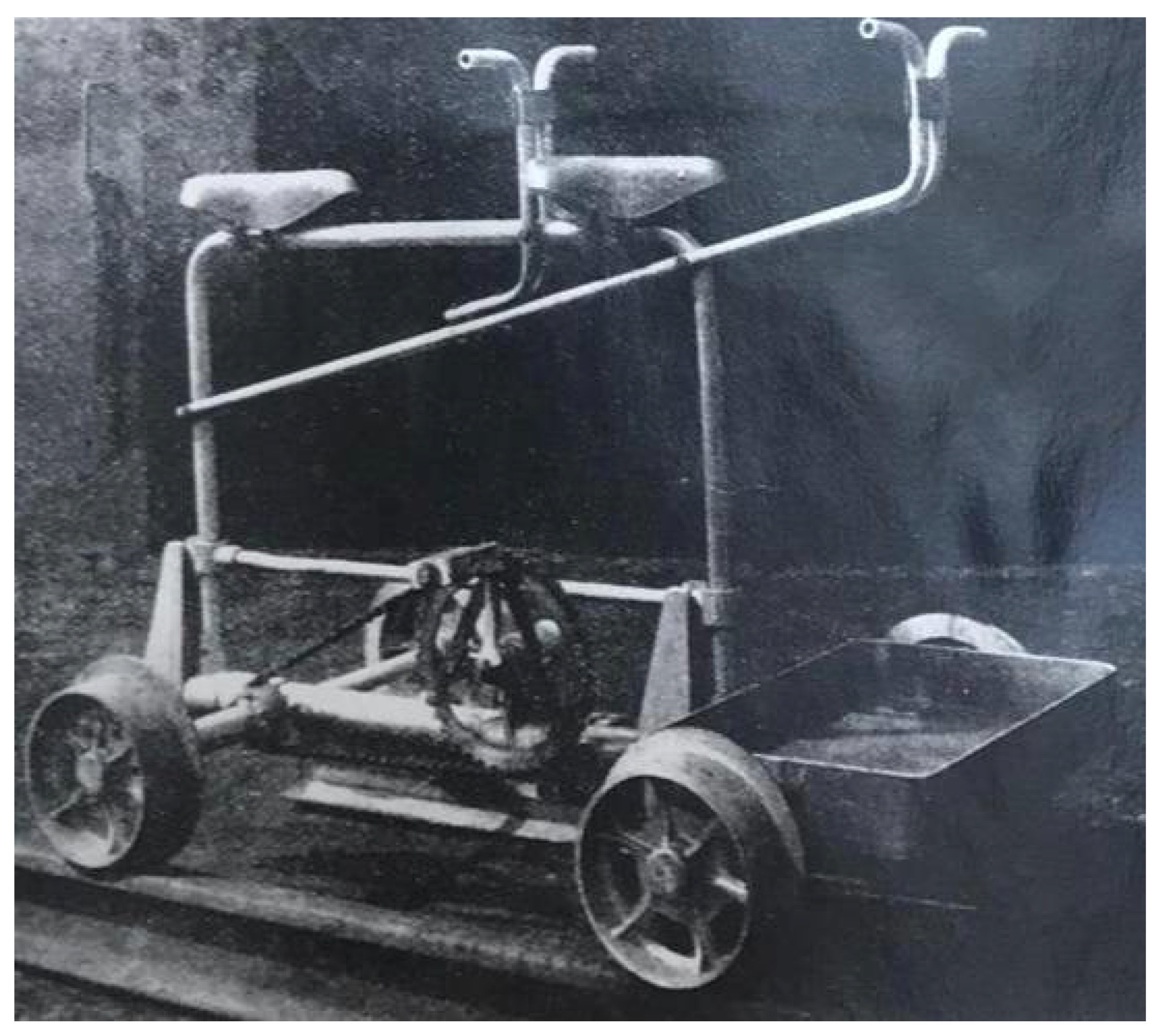
7]. Furthermore, due to the specific requirements of large groups of mine employees, significant distances are traveled between different mine workings, potentially several times per day. The desire to increase effectiveness and facilitate work has resulted in extensive development of improvised means of transport. Mine employees have readily adapted devices used on the surface to the conditions of underground workings. Due to the popularity of bicycles in urban spaces, their modified construction is common in underground mines, especially in Germany and Netherlands. Initially, underground bicycles were self-made creations, manufactured in mine workshops. In 1954, Scharf GmbH from Hamm, Germany introduced and sold the first miners’ bike, named Grubenflitzer [
9,
10]. During the years of the market presence of Grubenflitzer, numerous models of the bike were constructed. The basic model is presented in
Figure 1.
Miners’ bikes significantly reduce ineffective working time, which is caused by the necessity of moving between distant work places, and improves the miner’s work. However, due to the growing amount of machinery in mine workings, bike riding has become dangerous. Another major issue is rail deformation caused by floor heaving. These factors, in addition to increasingly restrictive safety regulations, led to the abandonment of miners’ bikes.
The main advantage of miners’ bikes was, first, a possibility of quick transport of people and small loads over significant distances in a relatively short time. This increased work effectiveness and reduced employee’s tiredness caused by the necessity of transport. Additional advantage of bicycles was the possibility to quickly evacuate accident victims.
The disadvantages leading to the abandonment of bikes were an inability to quickly assemble (making passing a complicated operation), the strong influence of floor heaving on track conditions, and a failure to meet safety regulations (because of aluminum construction and lack of illumination). An additional factor that contributed to the disappearance of bicycles was the growth in popularity of suspended railways, which led to the disappearance of typical rails from mine workings.
The current situation of Polish mining industry, particularly the constantly growing distances between shafts and mining areas, represents a market niche, namely, underground individual transport. The historic solutions presented above can provide guidelines for the development of a device to fill this niche.
The introduction of new adaptions of the miners’ bike must be preceded by conceptual work and research [
11,
12,
13]. The current study presents the process of development of a new miners’ bike, comprising five main stages:
Analysis of historic solutions.
Concept of the new construction of the individual means of transport.
Simulations to verify the concept.
Prototype of the new miners’ bike.
Real-life underground tests of the new means of individual transport.
Analysis of compliance with existing laws.
2. The New Means of Individual Transport Concept
From a thorough analysis of historic solutions of means of individual transport in underground mines, the main characteristics of the designed device can be specified:
Based on the features listed above, the idea of a miners’ bike utilizing suspended railway was developed. It was assumed that this new means of individual transport should be light enough to be assembled or disassembled by one person. It was necessary to take into account safety of user and environment. The result of conceptual work on this means of individual underground transport was the patent PL 418208 [
14], which was a basis for further construction development and necessary research and testing.
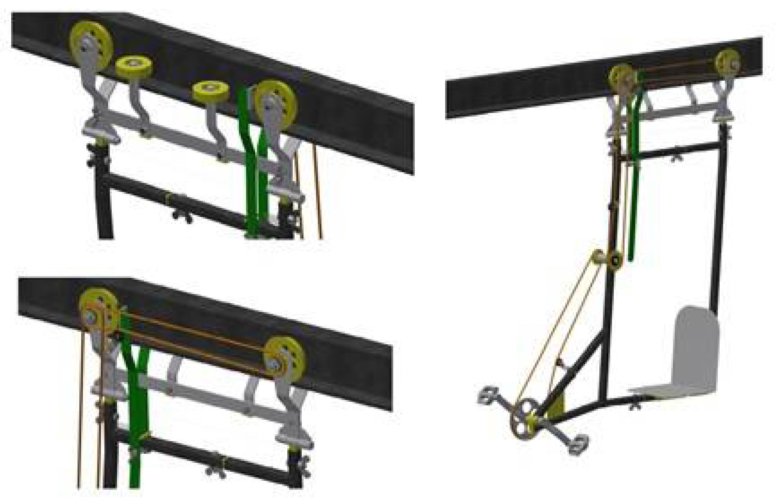
The specified requirements were the basis for a number of new miners’ bike construction proposals, which differ in terms of drive solution, placement of the drive and seat, and assembly of the elements. Examples of different miners’ bike solutions are shown in
Figure 2 and
Figure 3.
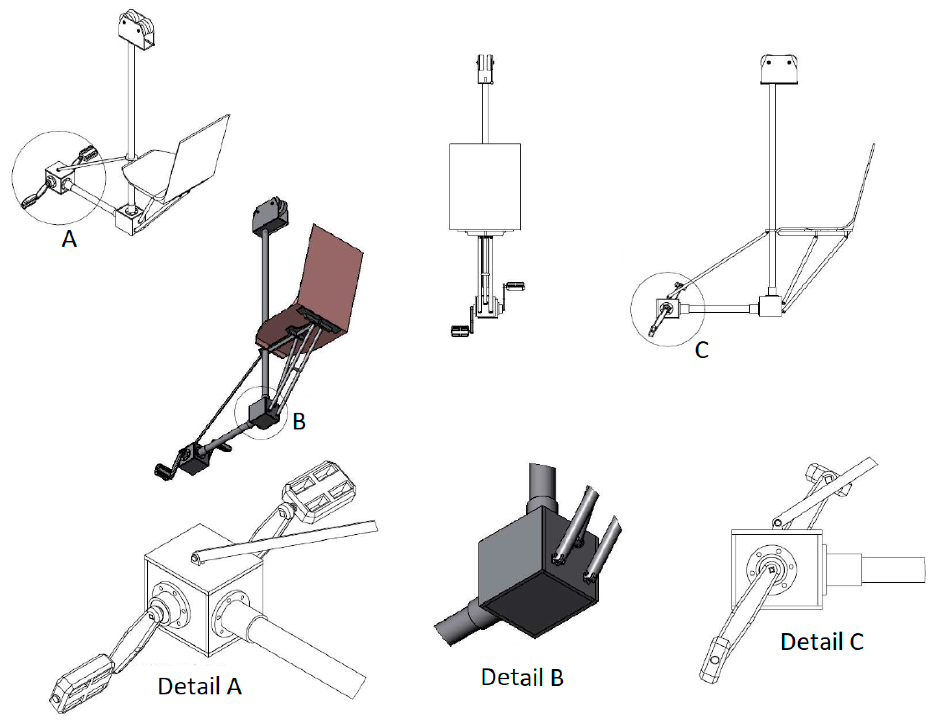
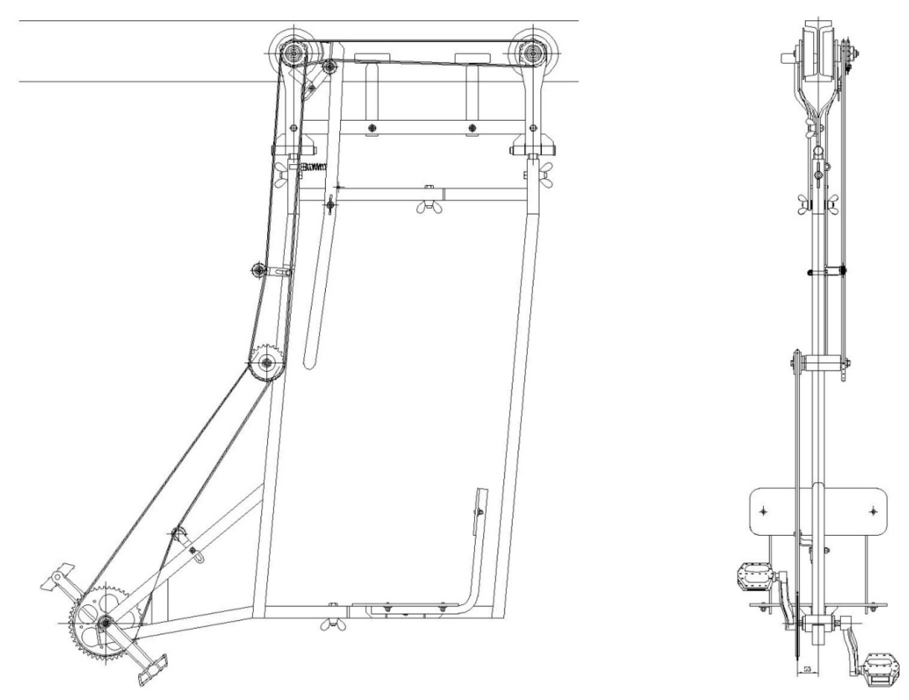
The model of the proposed miners’ bike concept is presented in
Figure 4. It was described in detail in [
15]. The main difference between this construction and the one presented in the patent is two vertical beams instead of one. Before assembling the prototype, numerical simulations were conducted to verify the correction of the concept assumptions [
16].
3. Simulations
3.1. Methodology
Simulations were conducted to address the issue of the bike ride. A virtual model of the new construction of the means of individual underground transport was built for testing using Working Model software. The aim of the simulations was to specify the technical characteristics of the bicycle. These characteristics comprise maximum speed, climbing ability, and average pressure required on the pedals. Simulations were conducted for two bicycle variants—one using steel wheels (variant no. 1) and the other using rubber-coated steel wheels (variant no. 2).
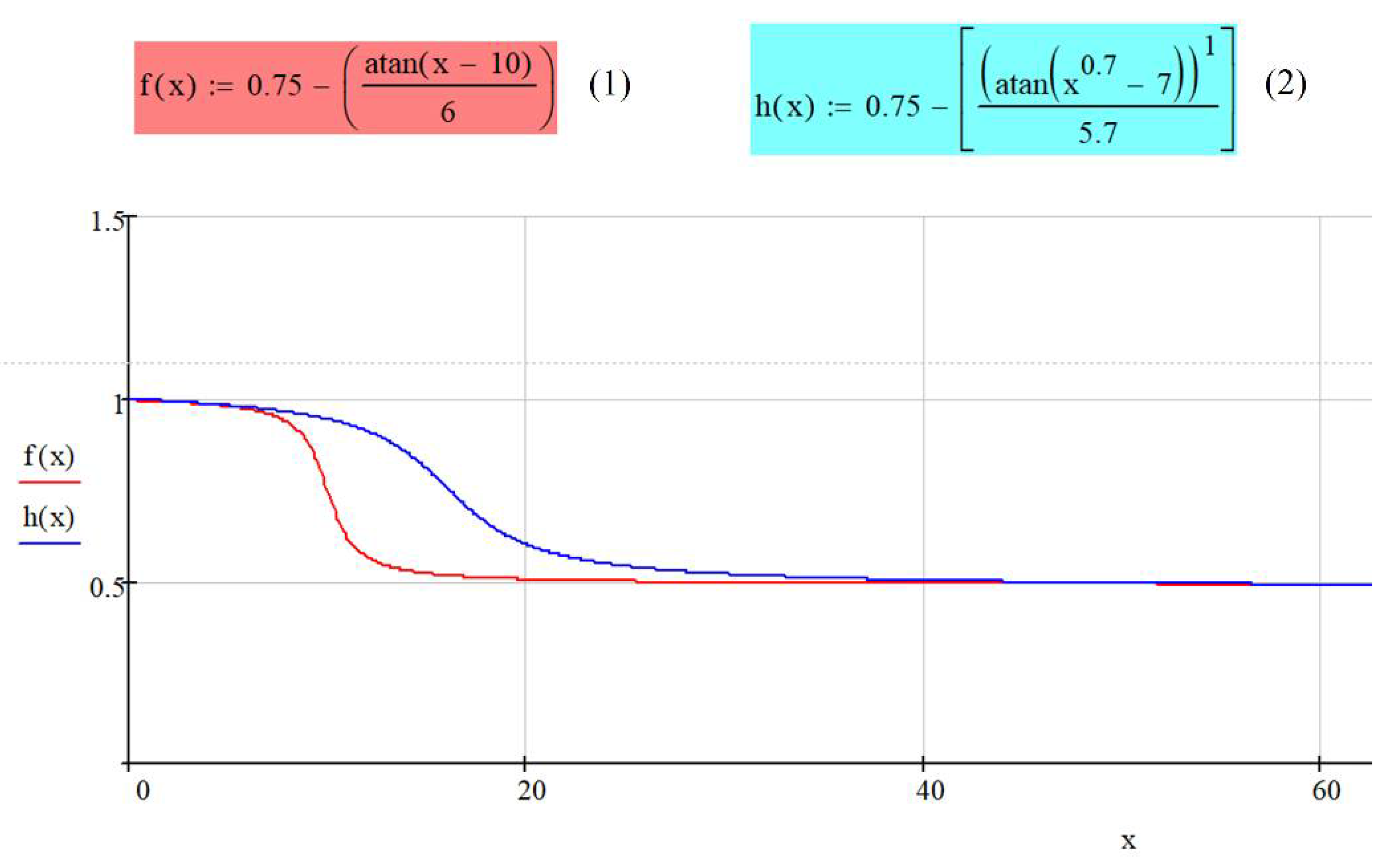
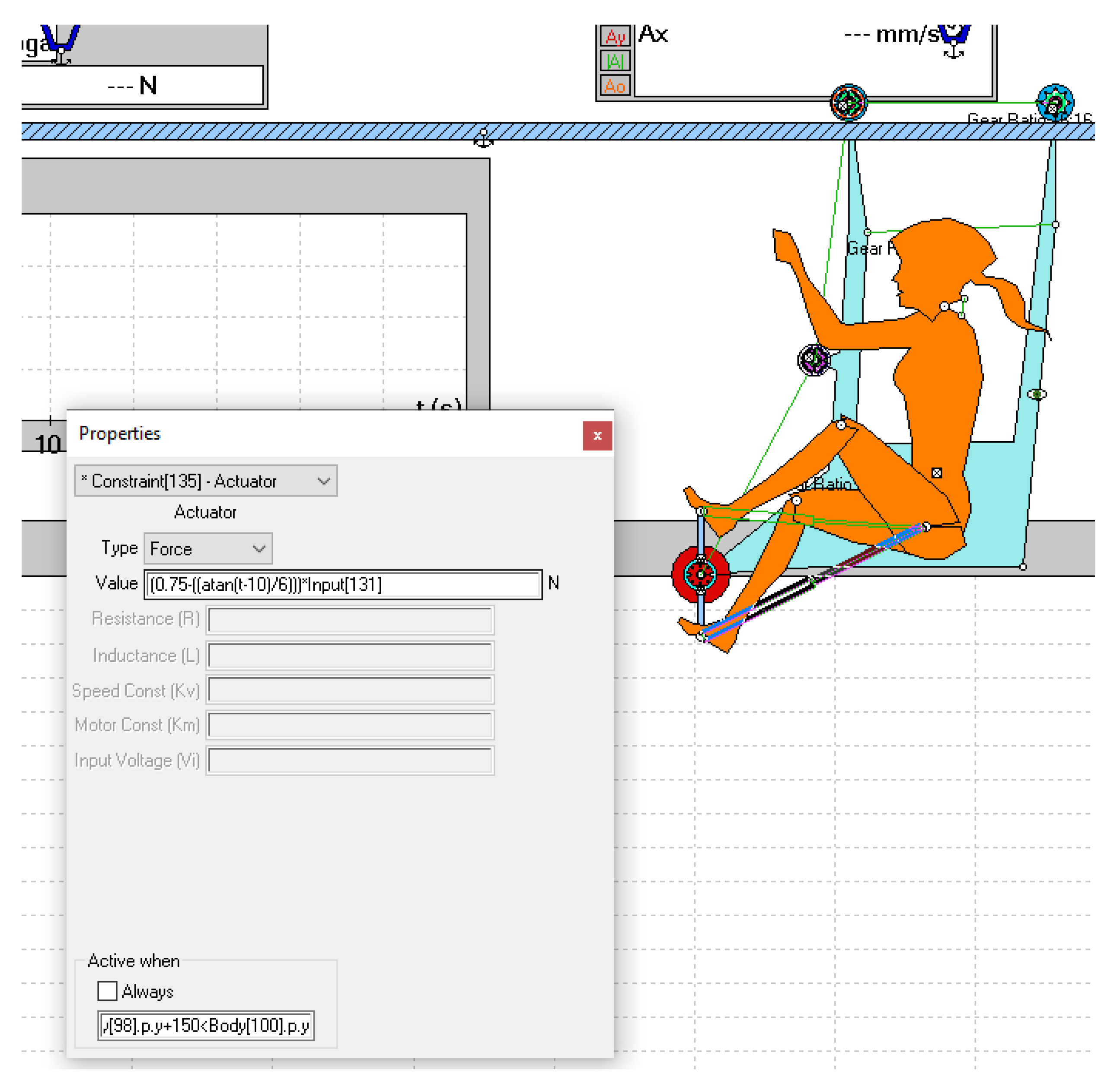
Observation of the traditional bike ride revealed that the pressure on the pedals during the initial phase of the ride is higher than after putting the bike into motion. Based on this observation, the relationship was determined between the pressure on the pedals at the initial moment t0 and its drop to 50% of the initial value after putting the bike into motion. A graph showing this relationship is presented in
Figure 5 and its implementation in Working Model software is shown in
Figure 6.
Simulations were conducted for a number of variants in which different parameters were changed, such as rail inclination, pressure on pedals, or additional load. The assumed weight of the bike was 40 kg and the weight of the user was 80 kg.
Simulations were conducted for a rail of varying inclination, gradually changing from 0 to 8° in 2° increments.
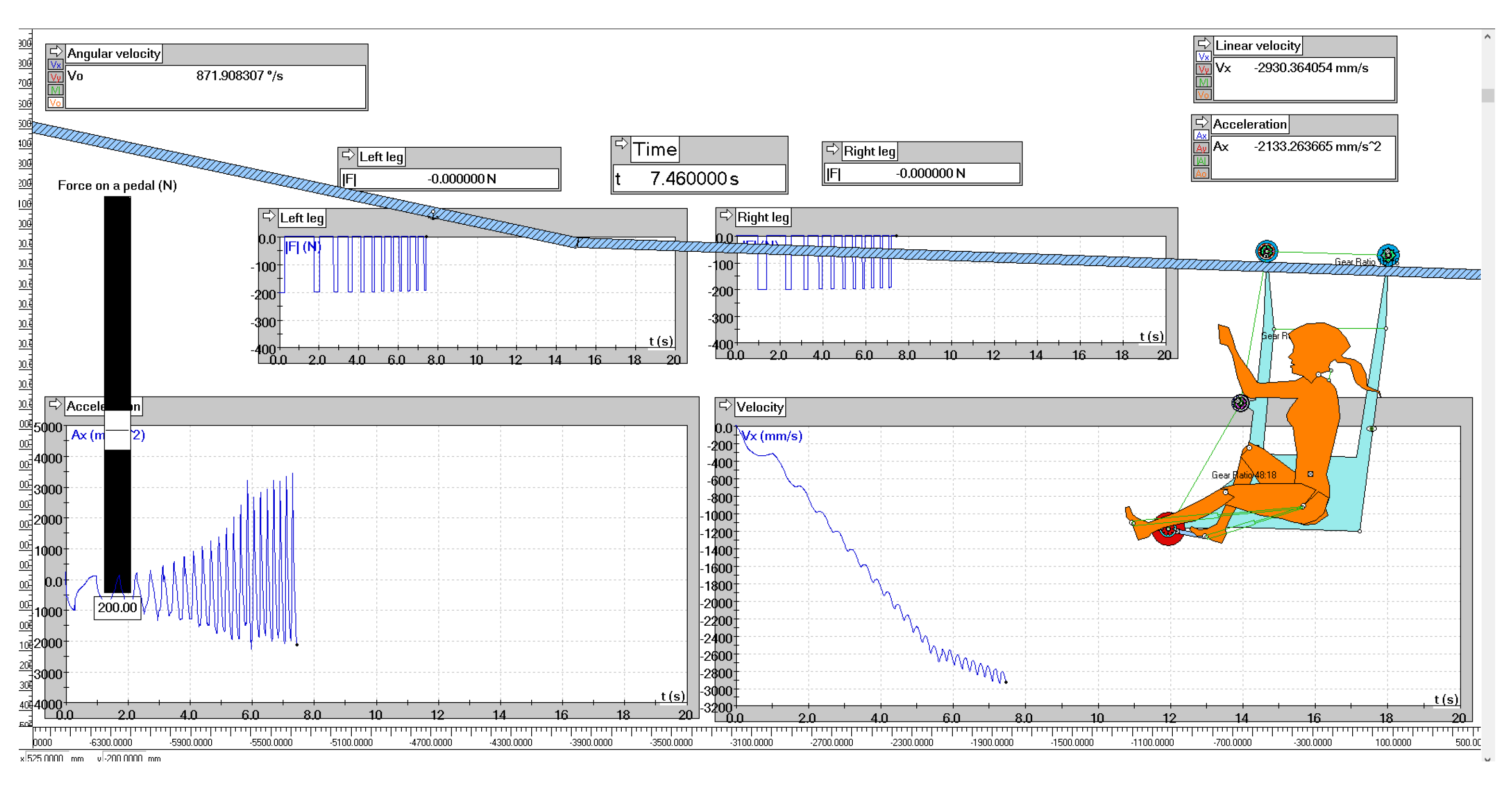
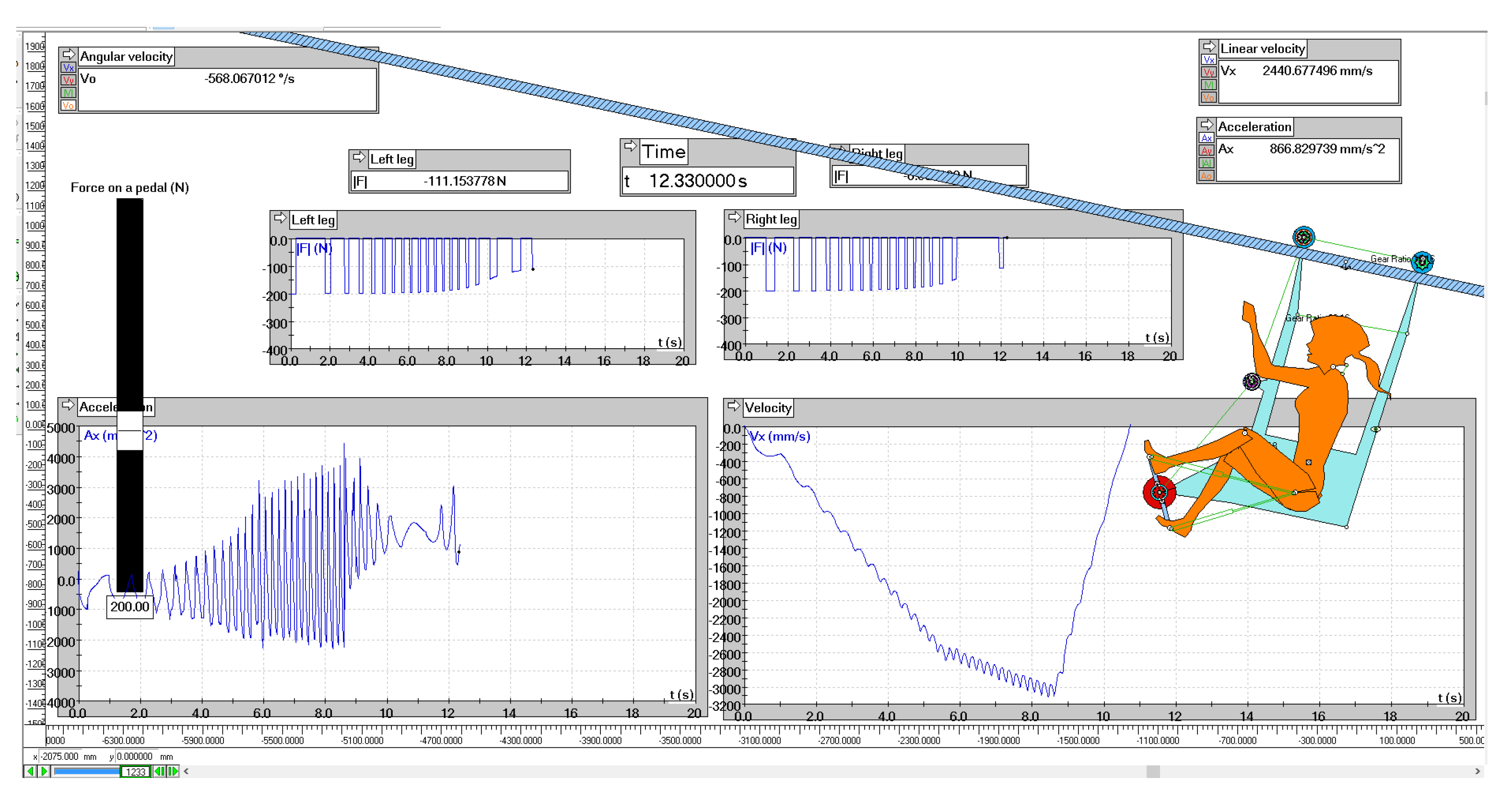
Figure 7,
Figure 8 and
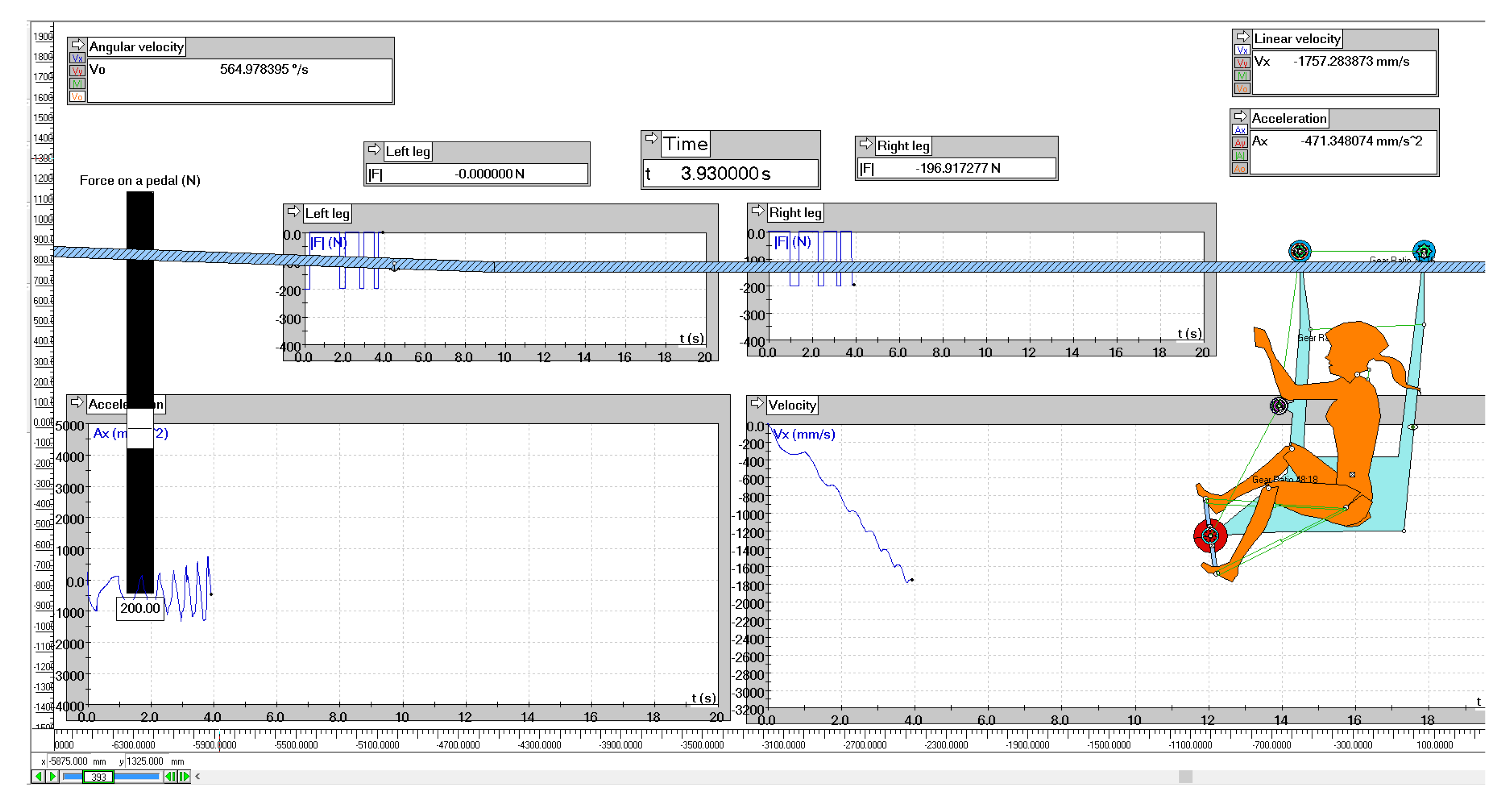
Figure 9 present different stages of the simulations; simulations of the bike ride without an additional load on the rail with inclination of 0° (
Figure 7), 2° (
Figure 8), and 8° (
Figure 9) are shown. The pressure on the pedals is equal to 200 N. The analyzed bike was equipped with rubber-covered steel wheels with a diameter of 113 mm.
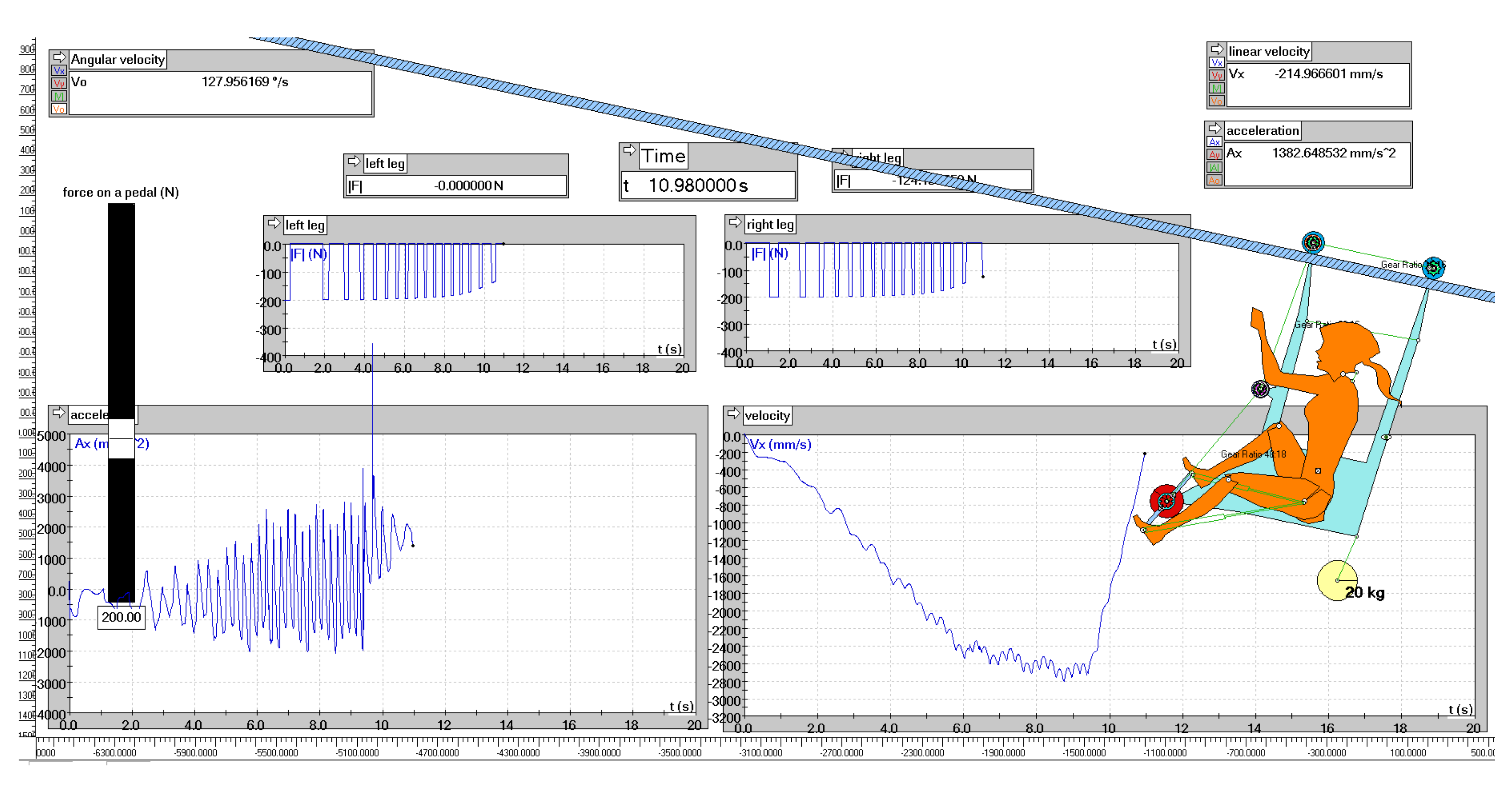
Figure 10 presents the simulation of the bicycle ride with an additional load equal to 20 kg on the rail with inclination of 8°. The assembly of the prototype is presented in
Figure 11.
3.2. Results of Simulations
Analysis of simulations revealed that pressure on pedals equal to 200 N is sufficient to set the bike into motion on the rail with inclinations of 0 and 2°. On the rail with an inclination of 8°, pressure of this value is insufficient, and the bike tends to slide down the inclination. The maximum speed of the bike with an additional load on the rail with an inclination of 2° is 3 m/s.
Simulations revealed that rubber-coated wheels are a better solution because setting the bike with steel wheels into motion requires 20% higher force. The pressure on the pedals needed to set the unladen bicycle into motion is 280 kN, whereas in the case of the bike with an additional load, it is equal to 375 N with a maximal load equal to 35 kg. The maximum inclination of the rail is 10° for the bicycle equipped with rubber-coated wheels. In terms of the existing equipment of mine workings, this value is satisfactory, because most of the rails in roadways have an inclination of up to 8°. Riding a bike on rails with higher values of inclination is theoretically possible, but requires pressure on pedals over 400 N, which was recognized to be too high.
4. Prototype
4.1. Construction of the Prototype and Underground Tests
Conducted simulations allowed verification of the assumptions of the selected solution and completion of the engineering design of the bike.
The constructed prototype was tested in real-life conditions to verify the results of the conducted simulations. The first field test was carried out in one of the coal mines of Jastrzębska Spółka Węglowa (JSW). The tested device was equipped with rubber-coated steel wheels, two side guiding wheels, and transmission gears with ratios of 42/16 and 22/16. The aim of the test was to determine the following issues:
possibility of assembly of the bike by one or two people and assembly time,
possibility of suspension of the bike on the rail by one or two people and its time,
stability of the bike and possibility of bike derailment, both with or without the use of guiding wheels.
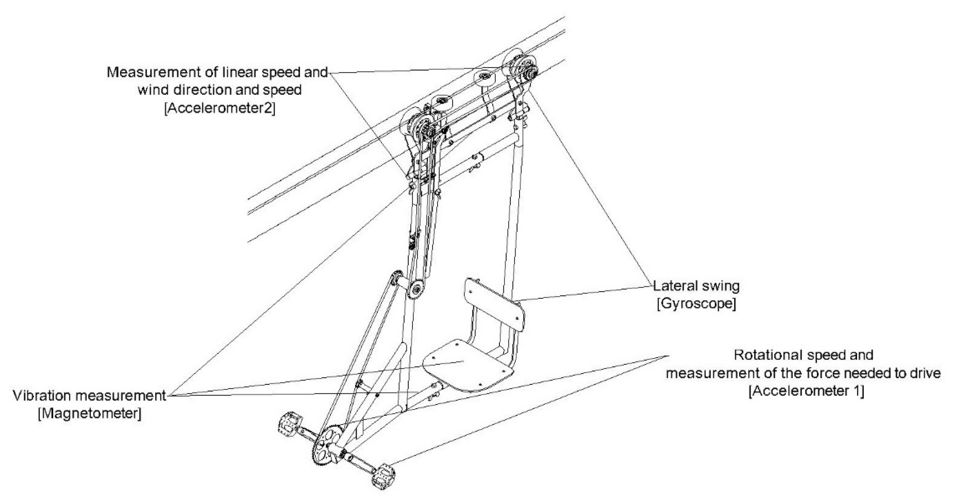
During the test, the means of individual underground transport was equipped with measuring equipment to determine:
linear and rotational velocity,
speed, direction, and force of wind,
vibration during ride,
side swing during ride.
The arrangement of the measuring equipment is presented in
Figure 12.
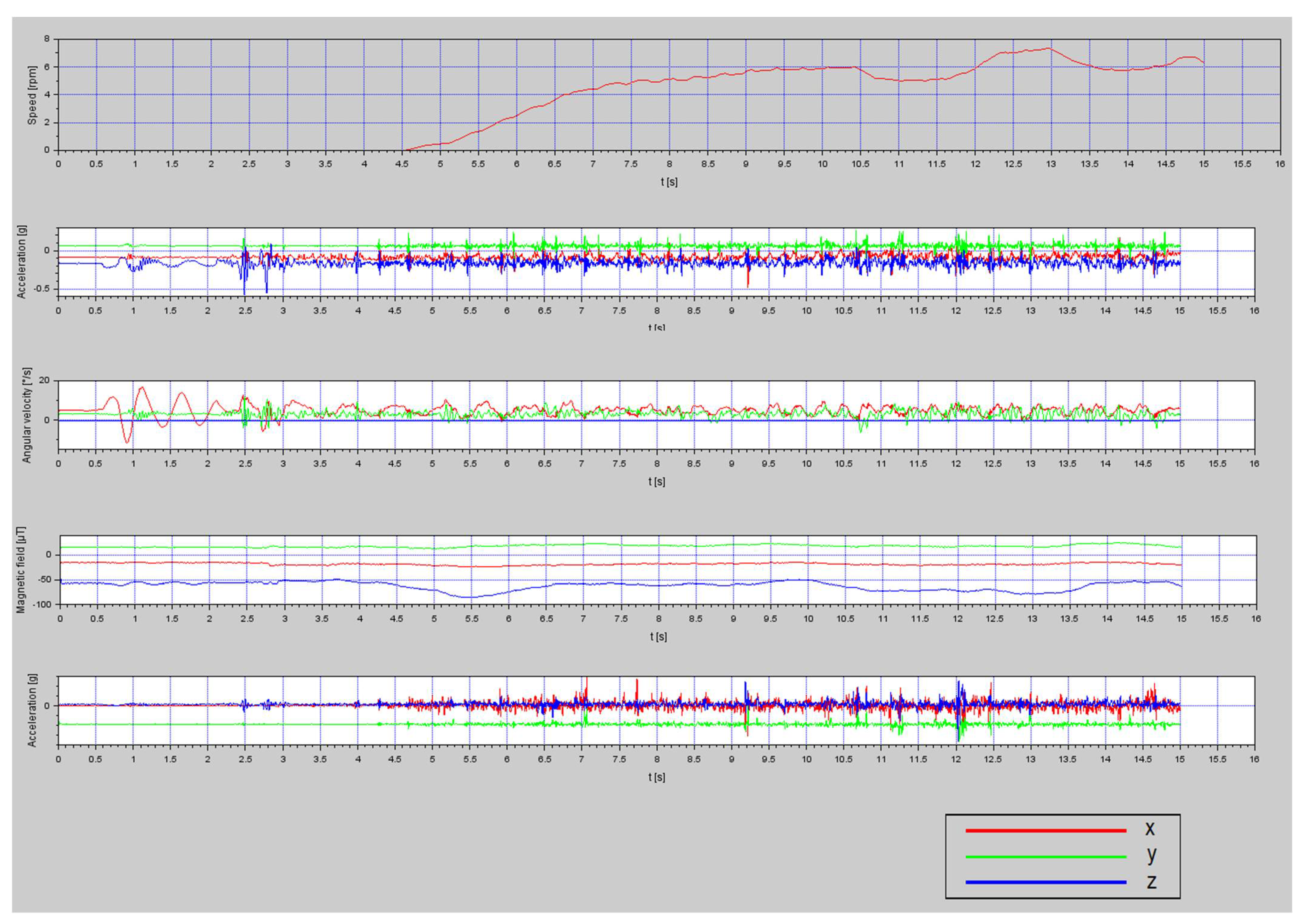
Figure 13 presents graphs of the quantities measured during the tests.
Analysis of graphs allowed interpretation of some elements of the bike ride. Peaks in the acceleration figures correspond to connections between rails. Values measured by gyroscopes also correspond to the lateral swing and load change of axles. Rotational and angular speed was measured, in addition to magnetic field, which allowed determination of a height profile.
4.2. Observations
The first underground tests revealed several defects of the construction, some of which were not noticed during simulations. One of the issues is the transmission gear ratio. It was found that the 46/16 ratio requires excessive effort for climbing uphill, and the 22/16 ratio is unable to provide satisfactory speed. It is thus recommended to use gears with 34 or 36 teeth.
Tests revealed that the weight of the bike’s prototype, which was 36 kg, is too high to allow for suspension of the bike on the rail by only one person. Assembly of the bike can be undertaken by one person, but it is easier and more convenient when it is undertaken by two people. Moreover, the application of wing screws should be considered to reduce the number of tools used for assembly.
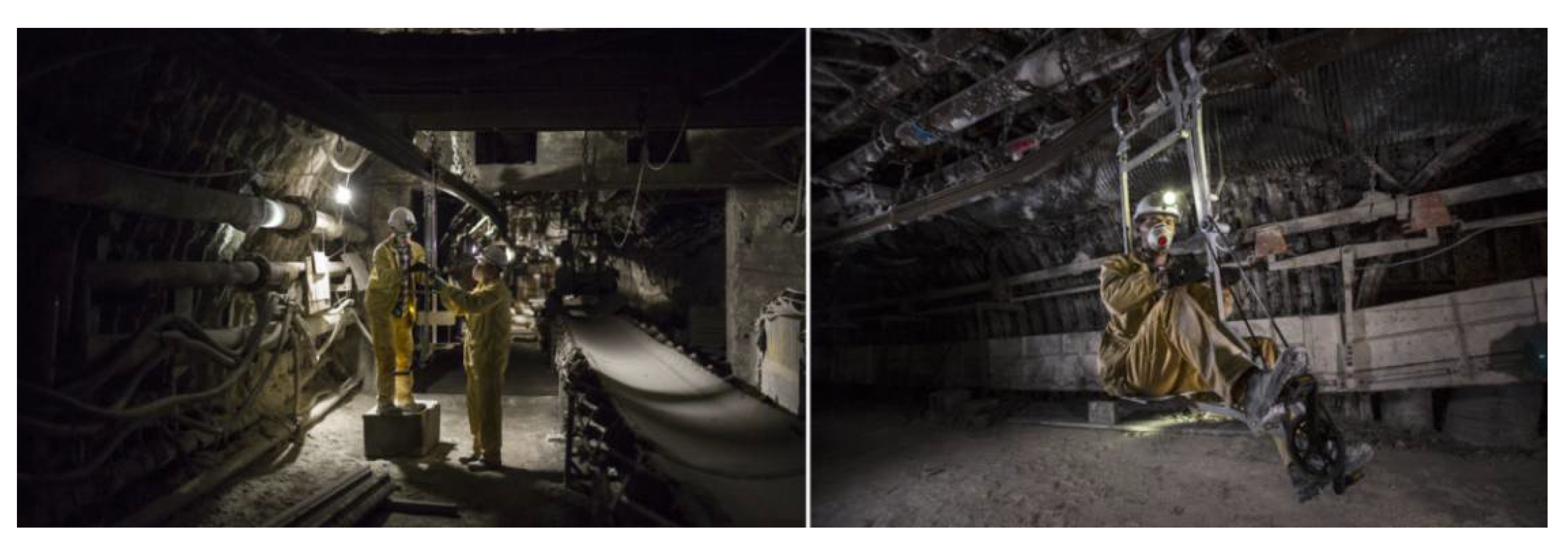
Figure 14 presents a view of the new miners’ bike during the tests in one of the coal mines in JSW.
Mounting the bike was another issue observed during tests, especially in cases when the user is a person of short stature, or the distance between the floor and the rail is large. Adding a type of stirrup should be considered, constructed to allow its length to be adjusted and to ensure it does not collide with working equipment.
Observation allowed positive verification of the simulation’s conclusion, that stability of the bike with a user on the seat is at a satisfactory level. A low center of gravity minimizes potential lateral swing. In addition, pedaling does not induce lateral swing. For this reason, removing the side guiding wheels should be considered, which would help to reduce bike’s mass.
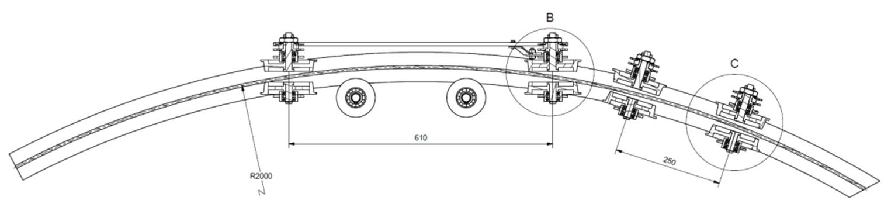
Tests also revealed an issue with the prototype’s cornering. In corners, the chain tends to slip off because of the frame skew. Different solutions to these problems were analyzed: strengthening the frame with side bars, using a lower flange of the wheels, application of swivel wheels, or shortening the wheelbase.
Shortening the frame and wheelbase was chosen as the most convenient and efficient means of solving the presented problem. Reduction of the frame length from 610 to 250 mm moving along the curve with a radius of 2000 mm was modeled. This simulation is shown in
Figure 15 and
Figure 16.
Real-life tests confirmed concerns about steel wheels, which tend to slide, even on straight and flat routes. It was concluded that one-wheel drive is sufficient, but the braking system should be improved.
4.3. Additional Underground Tests
After implementing changes designed to improve assembly and turning in the construction of the new miners’ bike, additional tests were conducted in the Lubelski Węgiel Bogdanka coal mine.
The shortened wheelbase improved the bike’s behavior on the corners, eliminating the derailment problem. The stability of the construction was again successfully validated. The suitability of using 34- and 36-tooth gears was not fully verified because of issues with the chain. However, empirical experience showed that it is right direction for development.
The presented construction of the means of individual underground transport was considered a promising opportunity for filling the niche of individual transport in coal mines. However, to become a fully marketable device it should be further developed. The braking system requires improvement because it is not yet satisfactory or efficient. The number of inclined workings in Polish coal mines also requires development of a drive. Because manual propulsion is not considered efficient enough, an electric drive should be designed and tested.
5. Legal Background
One of the reasons for the abandonment of the historic construction of underground bikes was their failure to comply with existing law. Current safety regulations are stricter than previously, so it is necessary to analyze them in terms of using the new construction of individual underground means of transport in operating mines. Analysis covers both proposed versions of the bike—with manual and electric propulsion.
The basis of the analysis was the bike’s status in terms of the EU Machinery Directive [
17]. This directive defines a machinery as “an assembly, fitted with or intended to be fitted with, a drive system other than directly applied human or animal effort, consisting of linked parts or components, at least one of which moves, and which are joined together for a specific application”. This means that a manually powered bike is not a machinery. However, the bicycle equipped with electric engine is a machinery.
Conformance testing has to be undertaken for the both versions of the presented means of individual underground transport. However, the version without an electric engine does not have to be compliance tested according to the Machinery Directive. Voluntary conformity assessment, e.g., with EN ISO 4210 Standards [
18], is recommended. It is also necessary to meet environmental requirements, which encompass the potentially explosive atmosphere in the case of underground coal mines.
The means of individual underground transport does not have to be conformance assessed pursuant to Polish Geological and Mining Law [
19], because it is not present on the list of products and devices for which such assessment is required. The fact that the miners’ bike is assembled on a suspended rail, which, in terms of Polish Law is an element of an underground railway, does not mean that the bike is also an element. This means that there is no legal basis for the bicycle to be officially approved by the President of the State Mining Authority.
However, the means of individual underground transport has to be conformance assessed and approved by the head of mining supervision of the mine (Kierownik Ruchu Zakładu Górniczego according to Polish law) on the basis of technical documentation and the protocol of the commission’s approval.
The compliance requirements are included in legal regulations [
19,
20]. The basis for approval for the use of the means of individual underground transport in underground mines is a technical documentation and maintenance manual, which must be delivered to the end user. Basing on the documentation and declaration of conformity, the means of individual underground transport may be used in underground mines. Good practice involves acquiring the opinion of a certification body (such as Certifying Body of KOMAG Institute of Mining and Technology), which contains independent and substantive assessment of the device.
In addition to fulfilling the requirements of the conformity assessment, the underground bicycle must be flame retardant, anti-electrostatic, and non-toxic. Moreover, it must comply with environmental requirements, which means that it also has to meet requirements of Polish mining law. It should be also noted that elements made of synthetic materials have to be assessed in terms of material requirements.
In case of version 1 (with manual propulsion), conformity assessment can be undertaken according to PN-EN ISO 80079-36:2016-07 Standard [
21], because a risk of ignition is caused by the drive’s moving parts and potential collision with the mine working equipment. Particularly important is that the relative percentage of light metals in construction elements must not exceed 15%. This is due to the properties of these metals, i.e., risk of sparking through friction on external elements.
The second version of the bicycle, equipped with an electric engine powered by battery, is a form of machinery and, in the case of its application in a potentially explosive atmosphere, it is necessary to conduct EU testing, including assessment of ignition risk and elements of explosion-proof construction. Taking into account modern technical capabilities, the only possible solution is to use an electric engine protected with an explosion-proof casing and battery cells using casing of the same property. Application of these elements would increase the bike’s weight, means the bike cannot be assembled, or the direction of the bike changed, by one person.
Lithium-ion technology has many advantages, but its main defect relative other types of batteries is low safety of use. Li-ion battery cells can explode as a result of high temperature caused by incorrect use. To prevent such a situation, different safety systems are implemented in energy supply systems [
22]. The following battery cell parameters must be monitored:
discharge current,
charger current,
voltage.
Both bicycle constructions do not require compliance with additional restrictions in terms of their use in workings where there is no risk of explosion. In the case of their use in workings where there is a risk of methane or coal dust explosion, both versions have to meet the requirements of the ATEX Directive.
6. Conclusions
The problem of individual transport in Polish underground coal mines remains unsolved. Due to constantly increasing distances and bad conditions of floors in mine workings, solving this issue requires an unconventional approach. Historic solutions of underground bicycles, which previously were in common use in underground mines, led to the development of a modern solution, utilizing existing mine equipment, namely, the suspended rail.
The development of a means of individual underground transport requires a multi-stage process, which comprises simulations, tests, and analysis. Simulations, conducted in Working Model software, allowed a prototype of an underground bicycle to be created. Real-life tests of this prototype in underground mines were key elements of the development process. These tests allowed identification of defects of the construction, which were not noticed during the simulations. In particular, these defects were the large mass, wide wheelbase, wrong gear transmission, and inability to easily get on or off the bike.
The defects listed above were successfully eliminated, however, some issues remain. One of these is the construction of a braking system, which was satisfactory in terms of the prototype, but requires improvements to make the bike marketable. In addition, manual propulsion might be not efficient enough in the steep inclined workings of Silesian coal mines. Thus, the application of an electric engine powered by li-ion battery cells is the most important field of improvement.
Historic construction of underground mine bicycles was abandoned because of, amongst other reasons, their lack of compliance with legal regulations. To ensure this failure is not repeated, it is necessary to analyze the applicability of the bicycle in terms of the existing legal regulations in Poland. The conducted analysis showed that the underground bicycle may be able to be applied in underground coal mines.
Simulations, tests, and analysis carried out during the development process of the underground bicycle verified its marketable features and identified new fields of development. In favorable conditions, the bicycle could improve the work of miners and help to rise miner’s effectiveness.


