Article

Catalytic Hot Gas Cleanup of Biomass Gasification Producer Gas via Steam Reforming Using Nickel-Supported Clay Minerals

1
Chemical Engineering Department, University of Louisiana at Lafayette, Lafayette, LA 70504, USA
2
Dave C. Swalm School of Chemical Engineering, Mississippi State University, Mississippi State, MS 39762, USA
*
Authors to whom correspondence should be addressed.
Energies 2021, 14(7), 1875; https://doi.org/10.3390/en14071875
Submission received: 18 February 2021 / Revised: 15 March 2021 / Accepted: 23 March 2021 / Published: 29 March 2021
(This article belongs to the Special Issue Bioenergy Conversion Technologies)

Abstract

:
Amongst the issues associated with the commercialization of biomass gasification, the presence of tars has been one of the most difficult aspects to address. Tars are an impurity generated from the gasifier and upon their condensation cause problems in downstream equipment including plugging, blockages, corrosion, and major catalyst deactivation. These problems lead to losses of efficiency as well as potential maintenance issues resulting from damaged processing units. Therefore, the removal of tars is necessary in order for the effective operation of a biomass gasification facility for the production of high-value fuel gas. The catalytic activity of montmorillonite and montmorillonite-supported nickel as tar removal catalysts will be investigated in this study. Ni-montmorillonite catalyst was prepared, characterized, and tested in a laboratory-scale reactor for its efficiency in reforming tars using naphthalene as a tar model compound. Efficacy of montmorillonite-supported nickel catalyst was tested as a function of nickel content, reaction temperature, steam-to-carbon ratio, and naphthalene loading. The results demonstrate that montmorillonite is catalytically active in removing naphthalene. Ni-montmorillonite had high activity towards naphthalene removal via steam reforming, with removal efficiencies greater than 99%. The activation energy was calculated for Ni-montmorillonite assuming first-order kinetics and was found to be 84.5 kJ/mole in accordance with the literature. Long-term activity tests were also conducted and showed that the catalyst was active with naphthalene removal efficiencies greater than 95% maintained over a 97-h test period. A little loss of activity was observed with a removal decrease from 97% to 95%. To investigate the decrease in catalytic activity, characterization of fresh and used catalyst samples was performed using thermogravimetric analysis, transmission electron microscopy, X-ray diffraction, and surface area analysis. The loss in activity was attributed to a decrease in catalyst surface area caused by nickel sintering and coke formation.

1. Introduction

With an increasing global population comes an increase in energy demand. The global energy demand has been increasing by an annual average of 1.8% over the past 10 years [1]. This demand is expected to increase by 15% from 2015 to 2030 and then by an additional 11% by 2040 [2]. Another concern is related to fossil fuels in their possible depletion as well as the effect the industry has towards climate change. Globally, more than 50% of the atmospheric CO2 increase, about 50% of the rise in the mean surface temperature, and the sea level rise (26–32%) between 1980 to 2010 have been linked to 90 carbon producers. Fossil fuel aerosols have been linked to an increase in surface temperature of 0.97 °C during the same period [3]. Owing to the increasing energy demand and overwhelming evidence of the negative impact of fossil fuels with regard to climate change, there has been a push for alternative and renewable energy sources. Lignocellulosic biomass is one of the renewable energy sources and is considered to be a potential feedstock for sustainable energy generation [4] amongst others such as wind, solar, geothermal energy, etc. [1,2]. In 2015, 4% of electricity came from renewable energy (RE) sources; however, the investment in RE technology continues to increase with a 14.1% increase in 2016 alone [1]. Moreover, biofuel energy sources are expected to increase to 25% by 2040 [2]. Gasification is a thermochemical process of converting biomass/carbonaceous waste to syngas (producer gas or synthesis gas). Amongst many applications, syngas produced from the process can be used in electricity generation, as a feedstock in transportation fuels and specialty chemical production, or can be further processed and separated for the production of hydrogen fuel [5]. From 2005 to 2015, the global biofuels production increased by 14.1% and by an additional 2.6% in 2016 alone [1]. In addition to tars, many impurities are present in fuel gases, including ammonia, hydrogen sulfide, hydrogen chloride, alkali and non-alkali metals, and particulate matter [6]. Tar removal has been proven to be a cost-intensive step in the purification of the resulting fuel gases. Tars are defined as a mixture of polycyclic hydrocarbons having molecular weights of greater than 72, ranging in size from one ring compound such as toluene to six-ring compounds such as coronene [7]. Catalyst deactivation, plugging, corrosion, and blockages that result from tar buildup cause many operational and maintenance difficulties. These problems lead to efficiency losses in the overall gasification process in terms of energy and material. Further converting tars to fuel gases [8] would improve efficiency as well as reduce the environmental and health impact that the carcinogenic tars pose [9]. Owing to the abovementioned reasons, cleanup of tars from biomass syngas is essential and will allow for economic and effective use of syngas in various applications.
Typically, tar removal techniques have been categorized into (a) physical, (b) thermal, and (c) catalytic [5]. The catalytic technique is of particular interest since instead of simply removing tars, they can be reformed into syngas, which will result in an increase in the gasification process efficiency. Catalysts for cleanup of tars have been categorized into the following groups: fluid catalytic cracking catalysts, calcined rocks, olivine, clay minerals, ferrous metal oxides, char, alkali metals, activated alumina, and transition metal catalysts [10]. Most of the research on catalytic tar removal has been focused on using dolomites, olivine, alkali metals, and nickel. Several researchers [4,11,12,13,14,15,16,17,18] have investigated dolomites owing to their availability, lower cost, and decent catalytic performance. However, issues with dolomites include deactivation due to coke formation leading to a gradual loss in the mechanical strength over time [14,16] and their relatively lower removal efficiencies [19]. Alkali metals is another group of catalysts that has been extensively investigated. Alkali metals are typically introduced by mixing with biomass or through wet impregnation. These catalysts exhibit good tar removal activity; however, there are some disadvantages as well. At high temperatures, these catalysts exhibit loss of activity due to particle agglomeration and volatility [10]. Recovery of these catalyst materials can be challenging owing to their mixing with biomass feed. Furthermore, separation of the char and ash containing alkalis can lead to additional expenses thus making the overall commercialization more difficult [8].
One of the most widely evaluated catalysts for syngas cleanup (tar removal) are nickel-based. Owing to the high steam and dry reforming activity, nickel-based catalysts allow for complete tar removal. While the cost of these catalysts is relatively higher compared to dolomites, their activity is 8–10 times higher under similar operating conditions [18,20]. The ideal catalytic steam reforming conditions were found to be between 650 °C and 800 °C for supported nickel catalysts; however, the optimum temperature might depend on the support media [21,22,23,24]. Operating in the upper end of the temperature range (near 800 °C) promotes greater activity and a longer lifetime for the nickel catalyst and operating at the lower end (around 650 °C) can lead to producing syngas rich in methane [24]. It was also observed that the commercial nickel-based catalysts synthesized for heavy hydrocarbon steam reforming are more suitable and active for tar reforming compared to those tailored for light hydrocarbons [25,26]. Shortcomings of nickel include the gradual loss in its catalytic activity over time. This comes as a result of carbon deposition (coking), sintering, and fouling. Nickel sintering causes irreversible loss of activity due to material changes; however, coke deposition on the surface of the catalyst can be eliminated through regeneration and its activity can thereby be restored [8].
Dolomites and olivine catalysts exhibit decent activity towards the removal of tars, but their inability to reduce tars to desired low levels has prompted several researchers to explore nickel-based dolomite and olivine catalysts [19,27,28,29]. Tar removal efficiencies of 97% using dolomite-supported Ni were reported by Wang et al. [19] while operating at 750 °C and maintaining a space velocity of 12,000 h−1. At a space velocity of 6000 h−1, Quitete et al. [30] observed tar (toluene) conversions of 68%, 76%, and 79% using Ni/LaAl11O18, Ni/La0.8Ce0.2 Al11O19, and Ni/CaAl12O19, respectively, at 700 °C. Swierczynski et al. [27] investigated the use of an olivine-supported Ni catalyst. They reported complete removal of toluene (which was used as a model compound for tar) with negligible coke deposition at temperatures above 650 °C [27]. Excellent catalytic activity was comparable to commercial nickel-based steam reforming catalysts [31]. At lower temperatures when there is risk of carbon deposition, it can be kept to a minimum by optimizing the loading of nickel on the support material. It was concluded that when using an olivine support, the ideal loading is 2.8 wt% Ni [32]. These results suggest that catalysts consisting of Ni supported on olivine or dolomite have demonstrable high activity for tar removal. Further, these catalysts are relatively less expensive in comparison to commercial steam reforming catalysts.
The other group of materials that have the tar removal potential includes clay minerals [10]. Clay minerals that are commonly available are montmorillonite, bentonite, kaolinite, and palygorskite. The catalytic activity of clay minerals for tar removal has been related to the effective pore diameter, high surface area, and acidity [31,33]. These minerals have several advantages owing to abundant availability and their being inexpensive. The main disadvantage of this material is its lower activity compared with dolomites and nickel catalysts. Liu et al. [34] obtained 99.5% tar conversion using the highly active Fe–Ni on palygorskite support at 700 °C [34].
Montmorillonite is a group of clay minerals composed of hydrous alluminosilicates. The surface area of montmorillonite (239 m2/g) is relatively high compared with dolomites (12 m2/g) and olivine (4 m2/g). The pore size of montmorillonite reported by Wang et al. is 5.2 nm [35]. High surface area results in an increase in active metal surface due to improved dispersion of metals on its surface. Wen et al. [31] reported that the catalytic activity of clay minerals increases with pore diameters greater than 0.7 nm, increase in the surface area, and acid strength. This pore size allows for the diffusion of the high-abundance molecules within tars, naphthalene and acenaphthene, with measured sizes of 0.499–0.681 nm and 0.65–0.681 nm, respectively [36]. The conclusion of increased activity correlating with acid strength agrees with Buchireddy et al. [33] whereby nickel on zeolite supports of various SiO2/Al2O3 were tested for tar (naphthalene) reforming.
Transition metal (group VIII) catalysts have been proven effective for steam and dry reforming applications. Owing to the relatively lower cost and high activity in comparison to cobalt, platinum, ruthenium, and rhodium, nickel has been widely used in such applications [8,37]. Thus, taking the advantages of clay mineral properties and nickel, this study evaluated montmorillonite-supported nickel for tar removal application. Owing to its stability and relatively high concentrations in tars, naphthalene was chosen as a tar model compound. Coll et al. [38] concluded that naphthalene is the least reactive compound among several tar model compounds tested, including benzene, toluene, naphthalene, antharacine, and pyrene. Furthermore, naphthalene is one of the most abundant polycyclic hydrocarbons produced during biomass gasification [10]. Moreover, several researchers [33,34,35,36] used naphthalene as a model compound in their studies and using the same model compound will allow comparison of kinetic data from this study. In this study, Ni-montmorillonite was synthesized, characterized, and tested for its efficiency in reforming naphthalene. Tests were also conducted using silica alumina (SiO2/Al2O3), and SiO2/Al2O3-supported nickel for comparison. Furthermore, the efficacy of the montmorillonite-supported nickel catalyst was tested as a function of nickel content, reaction temperature, naphthalene loading, steam-to-carbon ratio (S/C), and over extended time periods. Varying these operating conditions is common in experimental catalytic steam reforming using a variety of fuel sources [39].

2. Materials and Methods

2.1. Catalyst Preparation

Montmorillonite K10 was used as a support material and was obtained from Aldrich Chemicals. The chemical composition, surface area, and pore diameter for this material were obtained from Wang et al. [35] and are presented in Table 1. Nickel-impregnated montmorillonite was prepared using the incipient wetness impregnation method. The procedure detailed in [33] was used in this study; the only change being the support material (montmorillonite in place of zeolite). Five different catalysts were prepared with different nickel loadings of 0%, 2.5%, 7.5%, 15%, and 25%.

2.2. Experimental Setup

A schematic representation and details of the experimental setup can be found in the article by Buchireddy et al. [33]. The composition of feed gas used in this study was CO (20%), H2 (20%), CO2 (9%), CH4 (3%), and N2 (48%). This composition is representative of typical biomass syngas, although they vary widely depending on the feedstock and operating conditions. More specifically, these values were chosen based on the data from a pilot scale downdraft gasifier at Mississippi State University [40]. Details of naphthalene, water, and syngas feeding methodology including the detailed procedure are presented elsewhere [33]. Furthermore, unconverted naphthalene and gas collection procedures are listed in the same article.

2.3. Sampling and Analysis

”Unconverted naphthalene in the gas exit stream was measured by purging the exit gas stream from the catalytic reactor through a series of impingers. The impinger set up was performed according to the guideline for sampling and analysis of tars and particulates in biomass producer gases [41]. However, the impinger size was reduced to 25 mL. The temperature of the impingers placed in the ice bath was maintained at −5 to −10 °C using an ice and salt mixture in a bath. The temperature of the gases leaving the last impinger was 10–15 °C. Purged isopropyl alcohol from the impingers was then collected and stored at 4 °C for further analysis”.
[33]
Calculations of the operating conditions including naphthalene conversions, temperatures, steam-to-carbon ratio, and gas hourly space velocity were performed according to formulae provided by Buchireddy et al. [33].
“An Agilent 6890N gas chromatograph with flame ionization detector (GC-FID) was used to quantify the unconverted tars condensed in the isopropyl alcohol. A DB-5 (0.25 mm × 30 m) capillary column was used on the GC-FID and instrument parameters were set to separate and quantify aromatics (8 compounds) and PAHs (22 compounds), including naphthalene listed in tar sampling guide [41]. Samples were prepared with n-decane as an internal standard. Gas samples collected in 1-L bags were analyzed using a GC (SRI 8610) equipped with thermal conductivity detector. Gases H2, CO, N2, CO2, and CH4 were separated and quantified using a Carbosphere 80/100 (6 ft × 1/8”) stainless steel column (Alltech Associates Inc., IL, USA)”.
[33]

2.4. Catalyst Characterization

“Catalyst samples were characterized by powder X-ray diffraction (XRD) on a Rigaku Ultima III X-ray Diffractometer using Cu Kα (λ = 0.154 nm, 40 kV, 44mA) radiation to determine the nickel phase. The diffractographs were scanned in the range of 2θ between 10° and 80° with a sampling width of 0.02° and a scan speed of 4°/min. Transmission electron microscopy (TEM) was performed on JOEL model JEM-100 C XII (80 kV). Catalyst specimens were prepared by dispersing the powdered samples in IPA. The mixture was transferred onto a Cu grid and dried at room temperature. Microscopy analysis was performed on the specimens to determine nickel particle size. Surface area measurements of the fresh and spent catalysts was obtained from nitrogen adsorption isotherms at 77 K, using a Quantachrome AUTOSORB-I instrument. Samples were outgassed for 4 h at 180 °C prior to making these measurements. Thermogravimetric analysis was performed on a Versa Therm HS Thermogravimetric Analyzer (TGA) (Thermo Cahn Inc., Waltham, MA, USA), to determine the extent of coke deposition on the catalyst”
[33]

3. Results and Discussion

3.1. Catalytic Activity

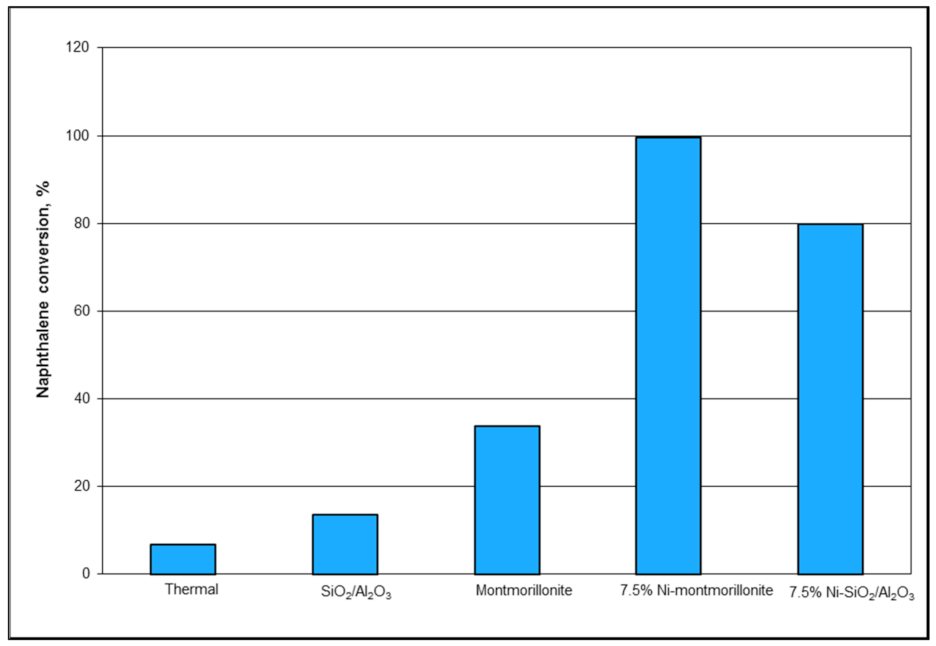
Naphthalene removal studies were conducted with different catalysts at 750 °C, S/C ratio of 5.0, gas hourly space velocity (GHSV) of 12,800 h−1, and naphthalene loading of 12 g/m3. Figure 1 shows the effect of catalysts and supports on naphthalene conversion. In the absence of a catalyst, naphthalene removal was limited to 6.7% via thermal cracking reaction as shown in Equation (1). As shown in Figure 1, montmorillonite had a higher removal efficiency at 33.8% compared to SiO2/Al2O3 (13.6%). Although the surface area of SiO2/Al2O3 (429 m2/g) was higher than that of montmorillonite (239 m2/g), montmorillonite was more effective. This could be attributed to the higher acidic strength of montmorillonite [31,33], which aids in the removal of naphthalene via the cracking reaction (Equation (1)). Impregnation of nickel on montmorillonite and SiO2/Al2O3 improved the naphthalene removal significantly. The conversion of naphthalene increased to 99.6% for Ni-montmorillonite and 79.8% for Ni-SiO2/Al2O3. This increase in catalytic activity is attributed to the steam reforming activity of nickel metal. Steam (Equation (2)) reforming is thermodynamically favored at high temperatures. Furthermore, dry reforming ((Equation (3)) could have contributed to naphthalene conversion.
C 10 H 8 C * + gas + lower   hydrocarbons
C 10 H 8 + 10 H 2 O 10 CO + 14 H 2
C 10 H 8 + 10 CO 2 20 CO + 4 H 2
CO + H 2 O CO 2 + H 2
2 CO CO 2 + C *
CH 4 + H 2 O CO + 3 H 2
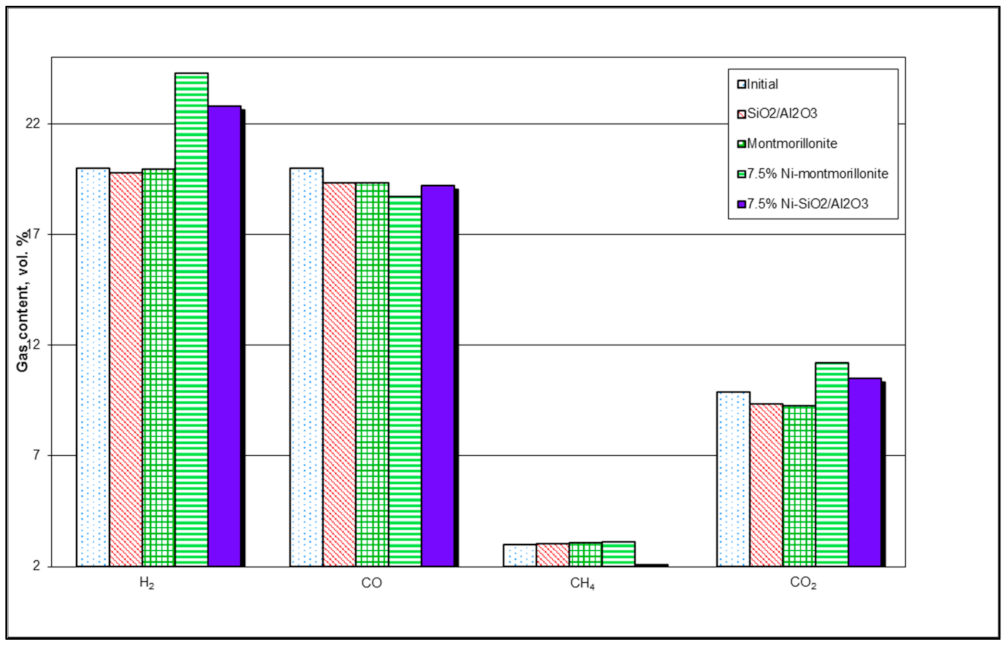
Figure 2 presents the variation in syngas composition for the different catalysts. The gas analysis was conducted on the gas samples collected at the end of the experiment. No substantial change occurred in the gas composition when SiO2/Al2O3 and montmorillonite were used as catalysts. However, there was an increase in H2 and CO2 content with a corresponding decrease in CO for the experiments performed with Ni-montmorillonite and Ni-SiO2/Al2O3 catalysts. This increase was attributed to the activity of nickel metal that promotes both water gas shift (Equation (4)) and methane reforming.
Table 2 presents the carbon balance for the same experiments. More than 95% of carbon was accounted for all the tests. Due to very low conversion of naphthalene for tests using support materials (SiO2/Al2O3 and montmorillonite), there was no noticeable increase in moles of carbon from syngas leaving the reactor. On the contrary, a slight decrease from 13.27 to 12.98 and 12.86 moles of carbon was observed for SiO2/Al2O3 and montmorillonite, respectively, although there was some naphthalene conversion. This decrease could be due to formation of coke on the surface of the catalyst and losses during analysis (to a smaller extent). Further, a decrease in syngas volume suggests the possibility of carbon deposition on catalyst surface from both gases and naphthalene. Presence of nickel promoted reforming of both naphthalene and syngas components resulting in an increased syngas carbon content. Volume of syngas increased in both cases, which could have resulted from steam/dry reforming as well as cracking of naphthalene into gaseous products. It should be noted that an increase in syngas volume does not translate to an increase in naphthalene conversion due to the possibility of steam reforming of syngas (Equations (4) and (6)).

3.2. Effect of Catalyst Bed Temperature

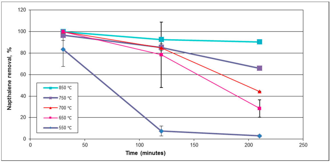
A series of tests were performed over a temperature range of 550–850 °C, S/C ratio of 5.0, gas hourly space velocity of 12,800 h−1, and naphthalene loading of 58 g/m3 to investigate the influence of temperature on naphthalene conversion. These tests showed that the activity of the catalyst increases with an increase in temperature from 550 °C to 850 °C, as presented in Figure 3. Naphthalene removal efficiency increased from 83% to 100% with an increase in temperature from 550 °C to 850 °C during the first 30 min of testing. However, a drop in the removal efficiency was noticed with time at all temperatures. At 700 °C, the removal efficiency dropped from 100% to 44% during the first 210 min. Similar trends were obtained at all the temperatures tested. This drop in the removal efficiency with time (Δη/Δt) could be attributed to the formation of coke on the catalyst. Coke covers the active sites on the catalyst surface thereby reducing the removal efficiency. It was also observed that removal efficiency (Δη/Δt) increases with an increase in temperature. From 30 min to 90 min, the removal efficiency dropped from 84% to 3% at 550 °C, whereas a drop from 100% to 90% was observed at 850 °C during the same time period. As the temperature increases, the reactivity of coke with water and carbon dioxide is favorable, thereby reducing coke formation [19].
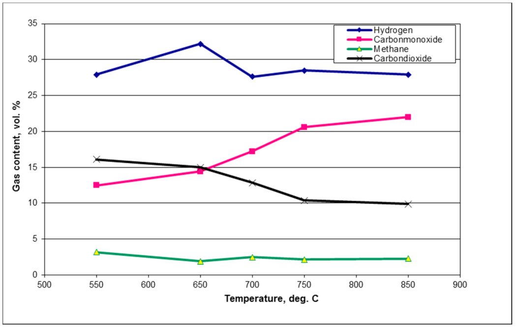
In general, hydrogen (H2) and carbon monoxide (CO) gas compositions in the exit gas stream are expected to be higher than the initial compositions due to the steam and dry reforming and thermal cracking reactions as shown in equations 1, 2, and 3. These reactions aid in conversion of naphthalene to H2, CO, and lower hydrocarbons. However, that was not the case as shown in Figure 4. There was an increase in the hydrogen and carbon dioxide (CO2) content associated with a decrease in carbon monoxide content at 550 °C. As the temperature increases from 550 to 675 °C, the water gas shift reaction is favorable as shown in Equation (4). Hence, the H2 and CO2 contents increase with a corresponding decrease in CO. At higher temperatures, above 700 °C, the reverse water gas shift reaction is thermodynamically favorable [27]. Hence, there is a decrease in H2 (32–28%) and CO2 (15–9.9%) while the CO content increases (15–22%) with an increase in temperature from 675 °C to 850 °C. Further, steam reforming of methane could contributed to the increase in H2 and CO. Furthermore, the relatively high values of H2/CO at lower temperatures could be due to the consumption of CO via the Boudouard reaction (Equation (5)).
Table 3 presents the carbon balance for the tests performed to evaluate the influence of temperature on naphthalene conversion. It should be noted that carbon accountability was greater than 92% for all the cases. Carbon from exit syngas increased with an increase in temperature. Syngas carbon increased from 14.47 to 17.54 moles with a corresponding increase in temperature from 550 °C to 850 °C. This increase could primarily be due to reforming and cracking of naphthalene as is evident from Table 3. Unconverted carbon from naphthalene dropped from 3.11 to 0.26 moles, which suggests that naphthalene was converted to gases in addition to the gas phase reactions as explained in the previous paragraph. Moreover, the increase in the syngas volume went up (from 19.11% to 26.62%) with an increase in temperature suggesting naphthalene conversion to gases via reforming and cracking reactions. The reaction of steam with gases might have contributed to an increase in exit syngas volume to an extent.

3.3. Effect of the Steam-to-Carbon (S/C) Ratio

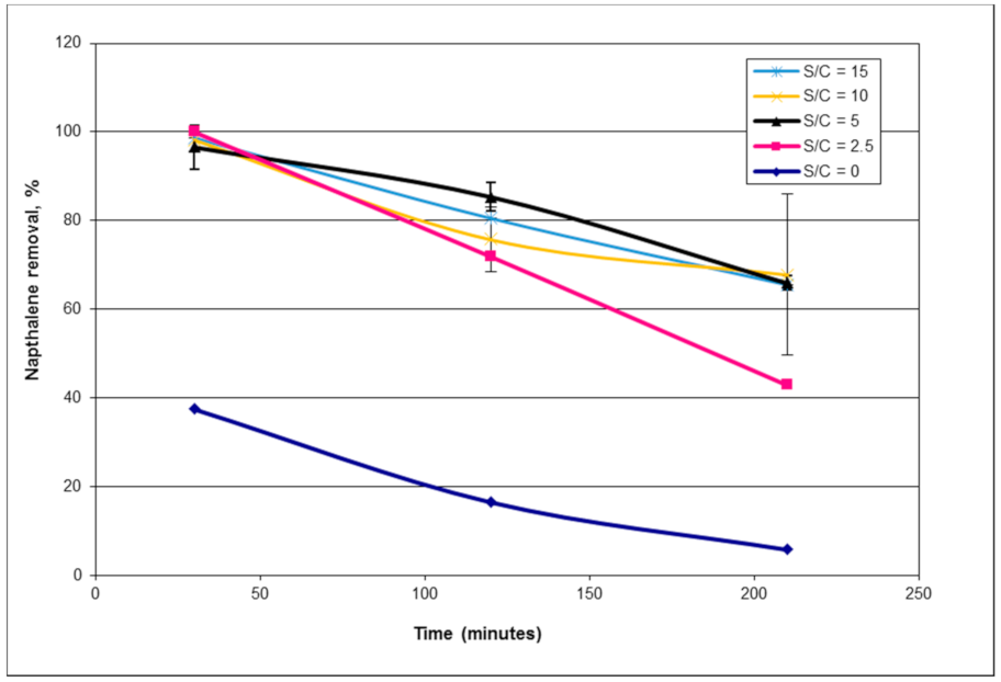
Figure 5 presents the effect of varying the S/C ratio on steam reforming of naphthalene. In the absence of steam, the removal efficiency of naphthalene was very low at 37%. When the S/C ratio was increased from 0 to 2.5, the removal efficiency of naphthalene increased from 37% to complete naphthalene conversion (100% removal). These results show that steam reforming (Equation (2)) is one of the dominant reactions that aid in the removal of hydrocarbons, including naphthalene.
No noticeable change in naphthalene removal was observed by increasing the S/C ratio from 2.5 to 15 as shown in Figure 5 (30 min). This could be attributed to the saturation of steam on the catalyst surface at S/C ratios above 2.5; similar results were reported by Simell et al. [17]. These observations were also reported by Garcia and Hüttinger [42] who studied the steam reforming of naphthalene over CaO and reported that the rate of reaction of hydrocarbons is independent of steam partial pressure when the ratio of steam to hydrocarbons is equal to or greater than the stoichiometric values. They assumed that the catalyst surface was saturated with steam at steam/naphthalene values greater than 10. However, a drop in the removal efficiency with time was observed at all S/C ratios. This drop can be attributed to formation of coke on the catalyst surface, nickel sintering, and/or formation of nickel aluminate spinel (NiAl2O4) at higher temperatures.
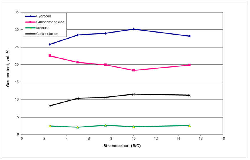
The effect of the S/C ratio on the gas composition is shown in Figure 6. There is an increase in the H2 and CO2 content while the CO content decreased with an increase in the S/C ratio from 2.5 to 10. This could be attributed to the fact that an increase in the S/C ratio increases the steam partial pressure which shifts the water gas shift reaction towards hydrogen formation [24]. Therefore, the H2 and CO2 contents increased from 25% to 31% and from 8.5% to 11.5%, respectively. This was accompanied by a decrease in CO content from 22.5% to 18.4% when the S/C ratio was increased from 2.5 to 10. However, these trends were reversed when the S/C ratio was increased from 10 to 15, which could be due to the dilution of gas at a higher S/C ratio.
Table 4 presents the carbon balance for the experiments conducted with various steam-to-carbon ratios. Mass closure values were slightly higher than 100% for a few runs and could be due to errors associated with accuracy of instrumentation and calibration using average efficiencies for unconverted naphthalene and gas compositions over time. An increase in exit syngas carbon was seen compared to the syngas carbon introduced to the reactor (13 to 17 moles). Similar to the earlier discussion (Table 3), the increase in exit syngas carbon was very likely caused by naphthalene conversion to gas phase products. Furthermore, the corresponding increase in the volume of exit syngas ranging between 17.18% to 26.28% was observed, which could have resulted from both reforming reactions of water with syngas components and naphthalene.

3.4. Effect of Nickel Content

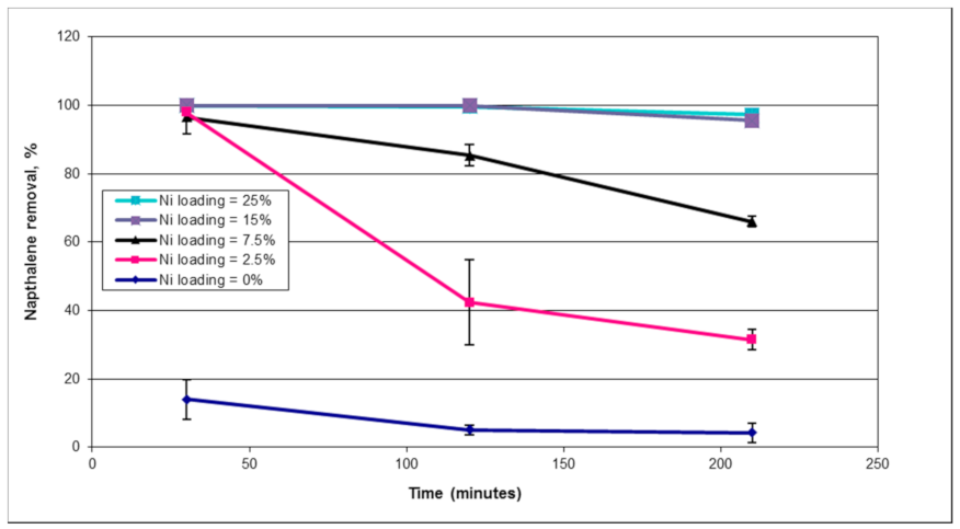
The influence of metal loading on naphthalene removal was evaluated by performing experiments with 2.5%, 7.5%, 15%, and 25% nickel-impregnated montmorillonite catalysts. Figure 7 presents the effect of nickel loading on naphthalene removal. In the absence of nickel, montmorillonite had a significantly lower activity leading to a naphthalene removal rate of 13%. Experiments were performed with an inert material to investigate the destruction of naphthalene via thermal cracking. The results showed that at 750 °C, naphthalene removal was 6.7%. This suggests that montmorillonite is an active catalyst in tar removal. This activity is attributed to montmorillonite’s acidic nature, high surface area, and large pore sizes as shown in Table 1 [35].
As shown in Figure 7, naphthalene removal rates increased with an increase in nickel content from 2.5% to 15%. Increasing the nickel loading from 15% to 25% did not result in any significant change in the removal efficiency. Similar results were reported by Bangala et al. [43] and Ishihara et al. [44]; however, Bangala et al. reported that naphthalene conversion dropped with an increase in nickel loading from 15% to 20%, which was not the case in our study. The variation in these results could be due to the support material used by Bangala et al., which was alumina [42]. Montmorillonite (239 m2/g) has a higher surface area compared to alumina (82 m2/g). Hence, the maximum metal loading would be higher for montmorillonite because of the higher surface area. Once the maximum metal loading is reached, the dispersion of metal on the support decreases, which results in lower activity of the catalyst.
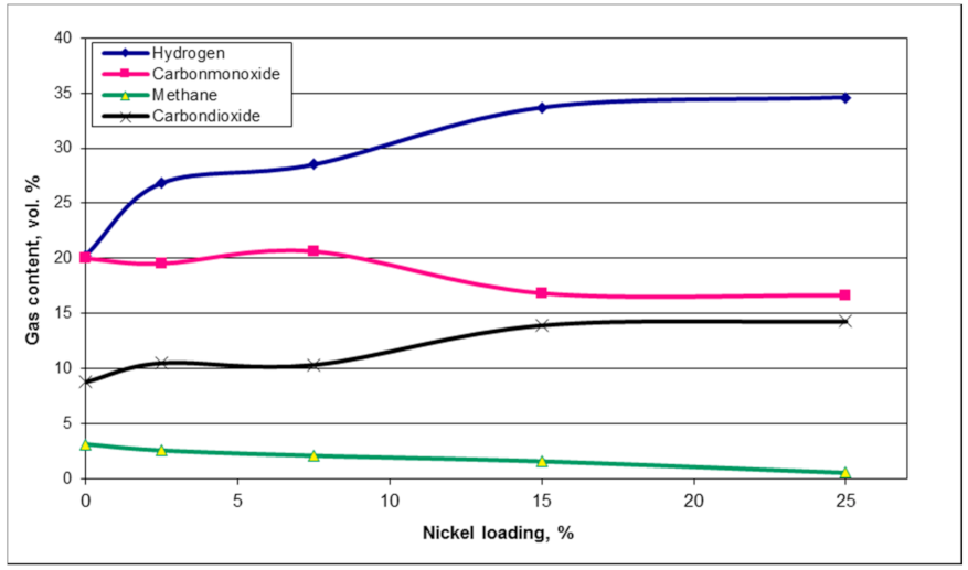
Figure 8 presents the effect of nickel loading on gas composition. No noticeable change in the composition of the input gas was observed in the absence of nickel (0% nickel). However, there was an increase in H2 and CO2 contents to 34% and 14%, respectively, with a corresponding decrease in CO from 20% to 16% when the nickel content was increased. This increase could be attributed to the water gas shift activity of nickel. With an increase in the nickel content, an increase in the H2/CO ratio was noticed as shown in Figure 8. Furthermore, the methane content decreased from 3% to 0.6% with an increase in the nickel content. This could be due to methane reforming, which is favorable at high temperatures (740–760 °C) [8].
Table 5 shows distribution of carbon from syngas and naphthalene and its mass balance. The closure was above 97% in almost all cases. With an increase in nickel content, carbon in unconverted naphthalene decreased from 4.18 to 0.05 moles while a corresponding increase of carbon in exit syngas was observed (13.43 to 16.31 moles). This suggests that carbon from reformed/cracked naphthalene was converted into gaseous products due to the steam reforming ability of nickel metal as explained in the earlier paragraphs, which could further be justified to an extent by the increase in exit gas volume from 0.5% to 41.89%.

3.5. Naphthalene Loading

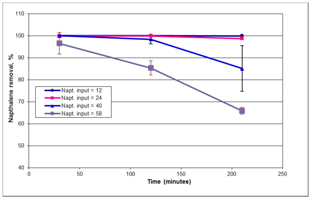
The effect of naphthalene loading on its removal efficiency is presented in Figure 9. There is a decrease in the removal efficiency with an increase in naphthalene loading. This could be due to the unavailability of active sites for naphthalene adsorption onto the catalyst surface with an increase in the naphthalene concentration. In contrast, Devi et al. [45] reported an increase in the removal efficiency with an increase in naphthalene loading. However, it should be noted that Devi’s experiments were carried out in a different naphthalene loading range (3.2–9.3 g/m3) [45].
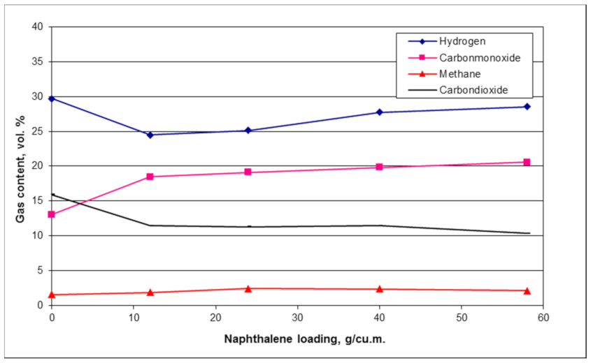
Figure 10 presents the effect of naphthalene loading on syngas composition. In the absence of naphthalene, it can be observed that there was an increase in H2 (20% to 29%) and CO2 (10% to 16%) with a corresponding decrease in CO (20% to 13%). This could be attributed to the water gas shift activity as shown in Equation (5). Furthermore, steam reforming of methane as shown in Equation (6) contributed to the increase in H2 and CO. The concentration of methane decreased from 3% to 1.6% in the absence of naphthalene. The water gas shift activity dropped substantially when naphthalene was introduced into the reactor (12 g/m3). The H2 and CO2 contents dropped with a corresponding increase in CO. This could be due to the increase in the partial pressure of naphthalene which increases its availability and allows for its reforming over water gas shift activity. A steady increase in CO and H2 contents was observed when the naphthalene loading was increased from 12 to 58 g/m3. This increase could be due to the steam and dry reforming of naphthalene that produces CO and H2 as shown in Equations (2) and (3).
Table 6 presents the carbon balance information for the tests conducted to evaluate the effect of naphthalene loading on its conversion in the presence of 7.5% Ni-montmorillonite. In the absence of naphthalene, the volume of exit syngas increased by 20.94%, which further strengthens the possibility of water reacting with syngas components (CO and CH4) via water gas shift and steam reforming reactions. However, the volume increase dropped by almost half to 9.99% when naphthalene was introduced while 100% of naphthalene (0.94 moles of C) was converted into gases. This suggests that the reaction between water and syngas dropped in the presence of naphthalene and supports the point made in the prior paragraph. Further increase in naphthalene (from 24 to 58 g/m3) contributed to an increase in carbon in the gas phase and an increase in gas volume (from 14% to 25%). Further, this can be explained by taking the case of naphthalene loading at 58 g/m3. The moles of carbon in syngas exit increased by 3.32, while 3.74 moles were lost from naphthalene. This suggests that 0.42 moles of carbon either went unaccounted and/or were deposited in the form of coke, which was not analyzed for these tests.

3.6. Estimation of Apparent Activation Energy

The first-order reaction model was assumed while estimating apparent activation energy, which has been widely accepted in tar removal studies using naphthalene as a model compound [46,47,48,49]. One of the advantages of this assumption is that a comparison of the results could be made with the available literature. Details of apparent energy and frequency factor calculations are presented elsewhere in detail [33].
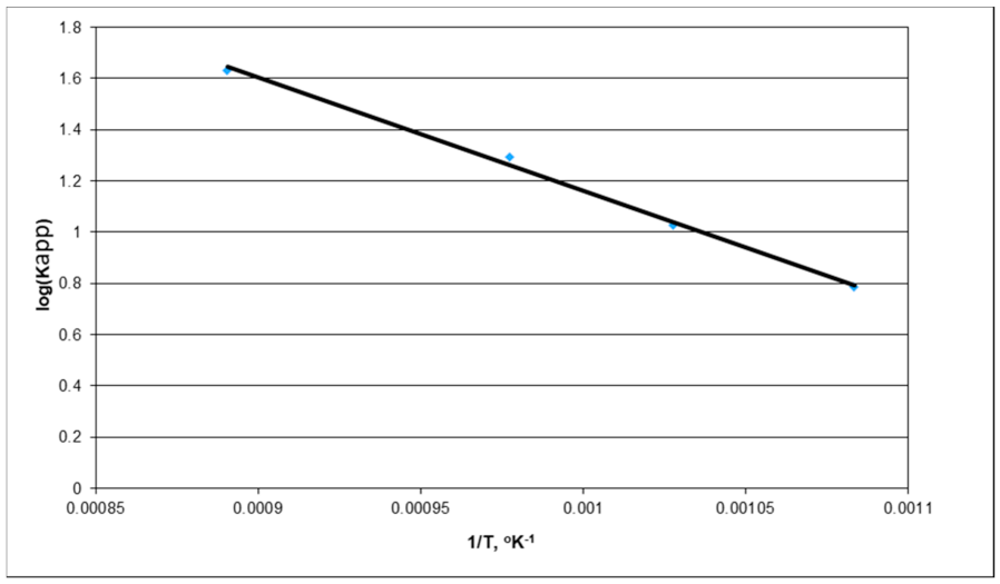
Experiments were conducted using 7.5% Ni-montmorillonite in the temperature range of 550–850 °C, naphthalene loading of 58 g/m3, to determine the activation energy. Activation energy and frequency factors were calculated using the Arrhenius plot shown in Figure 11 and are presented in Table 7. Activation energy for naphthalene removal was estimated to be 84.5 kJ/mole and is well within the range reported in the literature as shown in the Table 7. Table 7 also provides the activation energy and frequency factor for naphthalene removal reported by various researchers. The activation energy obtained in this study was within the range of activation energies reported, but on the lower side, which demonstrates the efficiency of the Ni-montmorillonite catalyst for tar removal. The only other study which reported a much lower activation energy was by Abu El-Rub et al. [47] who used fluid catalytic cracking and char as catalysts.

3.7. Catalyst Activity and Stability

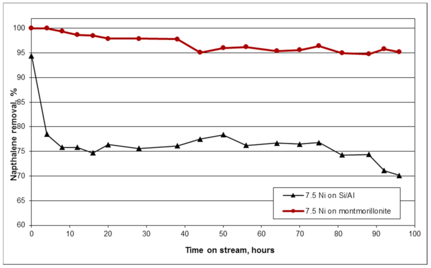
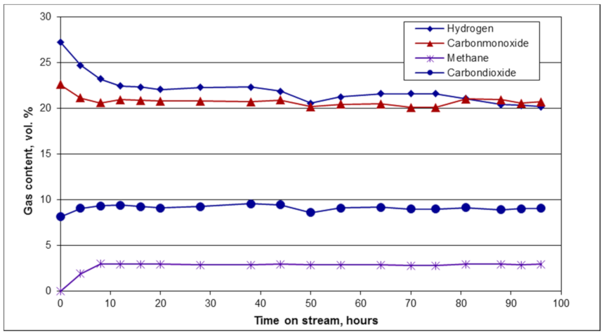
Experiments were conducted on 7.5% Ni-montmorillonite to evaluate the effect of catalytic activity on naphthalene conversion. Furthermore, an experiment was conducted on the 7.5% Ni-SiO2/Al2O3 catalyst to evaluate the effect of catalyst support. Figure 12 presents the naphthalene conversion with time on stream for the catalysts tested. There was a 4.5% decrease in the activity of 7.5% Ni-montmorillonite towards naphthalene removal. Naphthalene conversion dropped from 100 to 95.5% over a 97-h test period. The results from the test performed with 7.5% Ni-SiO2/Al2O3 showed a 24% drop in the activity from 94% to 70% over the test duration. This shows that montmorillonite support had a longer lasting activity than SiO2/Al2O3. The improved activity of montmorillonite support could be attributed to its acidic nature as discussed in Section 1. The variation of gas composition with time on stream is shown in Figure 13. An increase in the CO and H2 contents and a decrease in the CO2 and CH4 from the initial gas composition (H2 (20%), CO (20%), CO2 (10%), CH4 (3%)) was noticed in the first 10 h. However, no substantial change in the gas composition was noticed after the initial 10-h test period. These variations in the gas compositions could be due to multiple reactions occurring simultaneously as discussed earlier in Section 3.1 (Equations (1) and (5)).
Carbon balance data from Table 2, Table 3, Table 4, Table 5, Table 6 and Table 7 suggest that catalytic conversion allows for increase in energy density of syngas owing to tar cracking and reforming reactions by transferring carbon from naphthalene to the gas phase (syngas). Thus, catalytic tar removal is advantageous over physical tar removal techniques such as scrubbing where tars are merely transferred to a liquid phase without effectively utilizing the energy content available in tars. Moreover, further processing of the tar-laden liquid phase might be necessary suggesting catalytic tar removal’s advantages over physical methods.
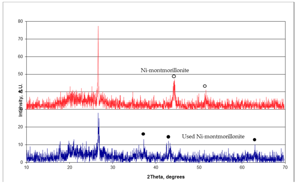
Characterization of fresh and used 7.5% Ni-montmorillonite (spent catalyst from the experiment that was performed over a period of 97 h at T—750 °C, S/C—5, GHSV—12,800 h−1, and naphthalene loading—12 g/m3) was conducted to elucidate the reasons behind catalytic deactivation such as formation of inactive nickel aluminate spinel phases at high reaction temperatures. X-ray diffraction was performed on the catalyst samples, the XRD patterns of which are shown in Figure 14. The catalyst samples are composed of NiO and Ni phases as shown in the figure. Peaks were identified at 2θ values of 37.2, 43.2, and 63 degrees on the fresh calcined sample which correspond to the NiO phase. However, only two peaks were identified at 2θ values of 44.3 and 51.8 degrees for the used sample. These peaks correspond to the Ni phase instead of the NiO phase [19,29,35,50]. This change in the NiO phase is due to the reduction of the NiO species on the catalyst during steam reforming, which was carried out under reduced (H2 and CO) atmosphere. Peaks could not be identified at 2θ values of 31, 37, 46, and 66 degrees, which are signature peaks for nickel aluminate [38]. This could be attributed to the absence of inactive nickel aluminate phase formation under the reaction conditions tested. Furthermore, the absence of nickel aluminate peaks could also be attributed to lower concentrations of nickel in the catalyst which makes it difficult to distinguish signature peaks from noise.
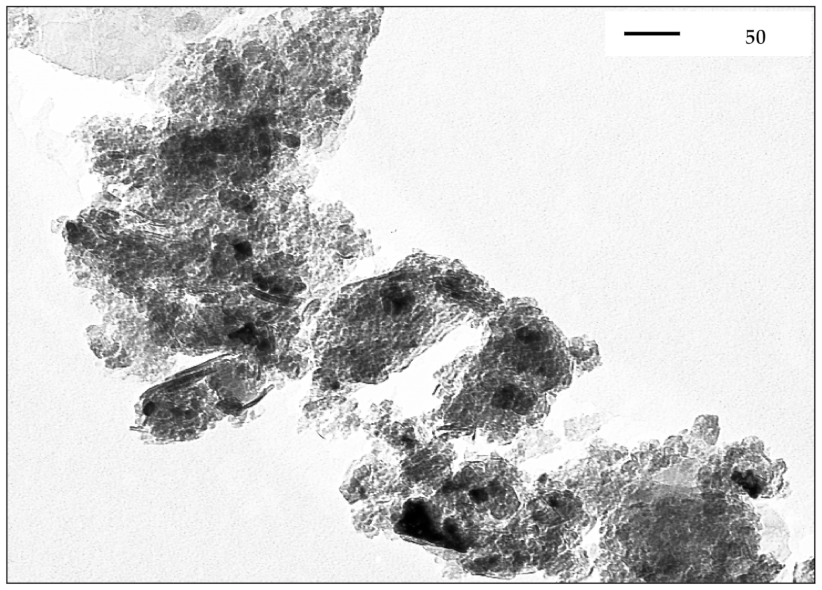
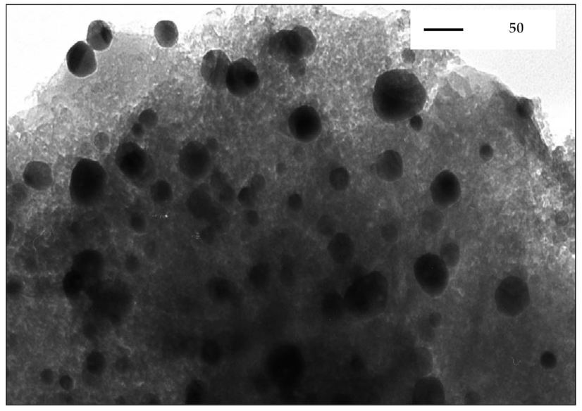
Transmission electron microscopy was performed on fresh and used catalyst to determine the size of nickel particles. Figure 15 and Figure 16 provide the TEM images at 40,000× magnification of fresh and post-run catalyst samples, respectively. The dark spherical spots on the catalyst surface represent the Ni particles. A broad particle size distribution is present in both cases. However, the metal particles on the used catalyst samples were larger compared to the fresh catalyst. Nickel particles on the fresh samples were up to 15 nm in size, which were smaller compared to the used catalyst. The size and shape of nickel particles reported by Ahmed et al. [51] were similar to the results from this study. The sizes of nickel particles were up to 50 nm on the used catalyst. This increase in the nickel particle size was due to sintering of nickel which occurs at high temperatures. Hence, one of the reasons for the decrease over time in the catalytic activity of Ni-montmorillonite can be attributed to the sintering of nickel particles. Sintering of nickel reduces the effective surface area of nickel which in turn reduces the number of active sites, reducing the catalytic activity.
Thermogravimetric analysis was performed to determine the amount of coke deposited on the spent catalysts, the results of which are provided in Table 8. The amount of coke deposited was lower for 7.5% Ni-montmorillonite (1.28%) compared with 7.5% Ni-SiO2/Al2O3 (3.21%). The lower coke formation on the Ni-montmorillonite in comparison to Ni-SiO2/Al2O3 could be due to the presence of 1.8% potassium as shown in Table 1 [35]. Alkali-promoted catalysts, especially potassium-promoted catalysts enhance the resistance to coke formation [50,52]. Hence, the presence of potassium could have resulted in a lower amount of coke deposited on Ni-montmorillonite. Although the amount of coke deposited on Ni-montmorillonite was limited to 1.28%, the presence of coke reduced the overall catalytic activity.
Surface area analysis of the catalysts was performed, the results of which are listed in Table 9. It can be seen that the surface area of both catalysts decreased by more than 50% after the experiment that was performed over a period of 97 h at T—750 °C, S/C—5, GHSV—12,800 h−1, and naphthalene loading—12 g/m3. This decrease in surface area could be due to the collapse of montmorillonite structure at high temperatures in the presence of steam. This decrease in surface area resulted in reduced availability of acidic sites for reaction. Furthermore, the accessibility of reactant molecules to nickel species encaged in the pores of the catalysts was reduced due to structural collapse. This results in a reduced activity of catalysts [53,54]. In addition, sintering of metal particles leads to a decrease in surface area of the support, which in turn reduces the catalytic activity [55].

4. Conclusions

Experiments were conducted using montmorillonite and Ni-montmorillonite as tar removal catalysts. Based on the results obtained, the following conclusions can be drawn.
  • Montmorillonite is a catalytically active material for naphthalene removal and its activity is attributed to its acidic nature.
  • Ni-montmorillonite was found to possess a very high catalytic activity for naphthalene removal. Complete removal was accomplished under the conditions tested. The activity of this catalyst was attributed to the nickel species and the acidic nature of montmorillonite support.
  • Naphthalene conversion increased with increasing nickel loading of up to 15%. Increasing the nickel content from 15 to 25% did not improve its conversion.
  • Long-term activity tests showed that Ni-montmorillonite achieved naphthalene conversions of greater than 95% with very little loss of activity during the 97-h stream test. The loss of activity was associated with the deactivation of the catalyst due to sintering of nickel, loss of surface area, and coking.
  • Ni-montmorillonite had a better activity compared with the conventional Ni-SiO2/Al2O3 catalyst and Ni-montmorillonite catalyst is more economical.
  • Apparent activation energy was estimated assuming the first-order reaction model. The calculated activation energy was 84.5 kJ/mole, which is comparable to data found in the literature.

Author Contributions

Conceptualization, P.R.B. and R.M.B.; Methodology and Investigation, P.R.B. and R.M.B.; Data curation, P.R.B., R.M.B., M.Z. and D.P.; Resources, R.M.B. and M.Z.; Project administration, R.M.B.; Writing-original draft preparation, P.R.B. and D.P.; Writing-review and editing, P.R.B., D.P., M.Z. and R.M.B.; Formal Analysis, P.R.B., R.M.B., M.Z. and D.P.; Validation, D.P.; Software, D.P. and M.Z.; Supervision, R.M.B. and M.Z. All authors have read and agreed to the published version of the manuscript.

Funding

This work was funded by the Sustainable Energy Research Center (SERC), Mississippi State University and Southeastern Region Sungrant Program.

Institutional Review Board Statement

Exclude.

Informed Consent Statement

Not Applicable.

Data Availability Statement

Exclude.

Acknowledgments

The authors would like to thank Mark White, Hossein Toghiani, and Amit Gujar for their technical input and assistance throughout the course of this study. The authors would like to thank Eugene Columbus and James Wooten for providing the necessary instrumentation. Furthermore, the authors would like to acknowledge Jared Jones, Eyad Algaishawi, and John Blakely for providing laboratory assistance.

Conflicts of Interest

The authors declare no conflict of interest.

References

  1. BP. BP Statistical Review of World Energy, 66th ed.; BP: London, UK, 2017. [Google Scholar]
  2. Administration USEI. International Energy Outlook; USEI: Santa Clarita, CA, USA, 2017. [Google Scholar]
  3. Ekwurzel, B.; Boneham, J.; Dalton, M.W.; Heede, R.; Mera, R.J.; Allen, M.R.; Frumhoff, P.C. The rise in global atmospheric CO2, surface temperature, and sea level from emissions traced to major carbon producers. Clim. Chang. 2017, 144, 579–590. [Google Scholar] [CrossRef] [Green Version]
  4. Devi, L.; Ptasinski, K.J.; Janssen, F.J.J.G.; van Paasen, S.V.B.; Bergman, P.C.A.; Kiel, J.H.A. Catalytic decomposition of biomass tars: Use of dolomite and untreated olivine. Renew. Energy 2005, 30, 565–587. [Google Scholar] [CrossRef]
  5. Milne, T.A.; Abatzoglou, N.; Evans, R.J. Biomass Gasifier “Tars”: Their Nature, Formation, and Conversion (trans: Energy USDo); National Renewable Energy Laboratory: Golden, CO, USA, 1998.
  6. Simell, P.A.; Bredenberg, J.B.s. Catalytic purification of tarry fuel gas. Fuel 1990, 69, 1219–1225. [Google Scholar] [CrossRef]
  7. Simell, P.; Ståhlberg, P.; Kurkela, E.; Albrecht, J.; Deutsch, S.; Sjöström, K. Provisional protocol for the sampling and anlaysis of tar and particulates in the gas from large-scale biomass gasifiers. Version 1998. Biomass Bioenergy 2000, 18, 19–38. [Google Scholar] [CrossRef]
  8. Sutton, D.; Kelleher, B.; Ross, J.R.H. Review of literature on catalysts for biomass gasification. Fuel Process. Technol. 2001, 73, 155–173. [Google Scholar] [CrossRef]
  9. Bridgwater, A.V. The technical and economic feasibility of biomass gasification for power generation. Fuel 1995, 74, 631–653. [Google Scholar] [CrossRef]
  10. Abu El-Rub, Z.; Bramer, E.A.; Brem, G. Review of Catalysts for Tar Elimination in Biomass Gasification Processes. Ind. Eng. Chem. Res. 2004, 43, 6911–6919. [Google Scholar] [CrossRef]
  11. Orío, A.; Corella, J.; Narváez, I. Performance of Different Dolomites on Hot Raw Gas Cleaning from Biomass Gasification with Air. Ind. Eng. Chem. Res. 1997, 36, 3800–3808. [Google Scholar] [CrossRef]
  12. Simell, P.A.; Leppälahti, J.K.; Bredenberg, J.B.s. Catalytic purification of tarry fuel gas with carbonate rocks and ferrous materials. Fuel 1992, 71, 211–218. [Google Scholar] [CrossRef]
  13. Corella, J.; Aznar, M.-P.; Gil, J.; Caballero, M.A. Biomass Gasification in Fluidized Bed:  Where to Locate the Dolomite to Improve Gasification? Energy Fuels 1999, 13, 1122–1127. [Google Scholar] [CrossRef]
  14. Delgado, J.; Aznar, M.P.; Corella, J. Calcined Dolomite, Magnesite, and Calcite for Cleaning Hot Gas from a Fluidized Bed Biomass Gasifier with Steam:  Life and Usefulness. Ind. Eng. Chem. Res. 1996, 35, 3637–3643. [Google Scholar] [CrossRef]
  15. Narváez, I.; Orío, A.; Aznar, M.P.; Corella, J. Biomass Gasification with Air in an Atmospheric Bubbling Fluidized Bed. Effect of Six Operational Variables on the Quality of the Produced Raw Gas. Ind. Eng. Chem. Res. 1996, 35, 2110–2120. [Google Scholar] [CrossRef]
  16. Simell, P.A.; Hakala, N.A.K.; Haario, H.E.; Krause, A.O.I. Catalytic Decomposition of Gasification Gas Tar with Benzene as the Model Compound. Ind. Eng. Chem. Res. 1997, 36, 42–51. [Google Scholar] [CrossRef]
  17. Simell, P.A.; Hirvensalo, E.K.; Smolander, V.T.; Krause, A.O.I. Steam Reforming of Gasification Gas Tar over Dolomite with Benzene as a Model Compound. Ind. Eng. Chem. Res. 1999, 38, 1250–1257. [Google Scholar] [CrossRef]
  18. Olivares, A.; Aznar, M.P.; Caballero, M.A.; Gil, J.; Francés, E.; Corella, J. Biomass Gasification:  Produced Gas Upgrading by In-Bed Use of Dolomite. Ind. Eng. Chem. Res. 1997, 36, 5220–5226. [Google Scholar] [CrossRef]
  19. Wang, T.; Chang, J.; Lv, P.; Zhu, J. Novel Catalyst for Cracking of Biomass Tar. Energy Fuels 2005, 19, 22–27. [Google Scholar] [CrossRef]
  20. Corella, J.; Orío, A.; Aznar, P. Biomass Gasification with Air in Fluidized Bed:  Reforming of the Gas Composition with Commercial Steam Reforming Catalysts. Ind. Eng. Chem. Res. 1998, 37, 4617–4624. [Google Scholar] [CrossRef]
  21. Gao, N.; Liu, S.; Han, Y.; Xing, C.; Li, A. Steam reforming of biomass tar for hydrogen production over NiO/ceramic foam catalyst. Int. J. Hydrog. Energy 2015, 40, 7983–7990. [Google Scholar] [CrossRef]
  22. Sekine, Y.; Mukai, D.; Murai, Y.; Tochiya, S.; Izutsu, Y.; Sekiguchi, K.; Hosomura, N.; Arai, H.; Kikuchi, E.; Sugiura, Y. Steam reforming of toluene over perovskite-supported Ni catalysts. Appl. Catal. A Gen. 2013, 451 (Suppl. C), 160–167. [Google Scholar] [CrossRef]
  23. García-Labiano, F.; Gayán, P.; de Diego, L.F.; Abad, A.; Mendiara, T.; Adánez, J.; Nacken, M.; Heidenreich, S. Tar abatement in a fixed bed catalytic filter candle during biomass gasification in a dual fluidized bed. Appl. Catal. B Environ. 2016, 188 (Suppl. C), 198–206. [Google Scholar] [CrossRef]
  24. Khonde, R.; Nanda, J.; Chaurasia, A. Experimental investigation of catalytic cracking of rice husk tar for hydrogen production. J. Mater. Cycles Waste Manag. 2018, 20, 1310–1319. [Google Scholar] [CrossRef]
  25. Caballero, M.A.; Aznar, M.P.; Gil, J.; Martín, J.A.; Francés, E.; Corella, J. Commercial Steam Reforming Catalysts to Improve Biomass Gasification with Steam−Oxygen Mixtures. 1. Hot Gas Upgrading by the Catalytic Reactor. Ind. Eng. Chem. Res. 1997, 36, 5227–5239. [Google Scholar] [CrossRef]
  26. Aznar, M.P.; Caballero, M.A.; Gil, J.; Martín, J.A.; Corella, J. Commercial Steam Reforming Catalysts to Improve Biomass Gasification with Steam−Oxygen Mixtures. 2. Catalytic Tar Removal. Ind. Eng. Chem. Res. 1998, 37, 2668–2680. [Google Scholar] [CrossRef]
  27. Świerczyński, D.; Libs, S.; Courson, C.; Kiennemann, A. Steam reforming of tar from a biomass gasification process over Ni/olivine catalyst using toluene as a model compound. Appl. Catal. B Environ. 2007, 74, 211–222. [Google Scholar] [CrossRef]
  28. Wang, T.J.; Chang, J.; Wu, C.Z.; Fu, Y.; Chen, Y. The steam reforming of naphthalene over a nickel–dolomite cracking catalyst. Biomass Bioenergy 2005, 28, 508–514. [Google Scholar] [CrossRef]
  29. Zhang, R.; Wang, Y.; Brown, R.C. Steam reforming of tar compounds over Ni/olivine catalysts doped with CeO2. Energy Convers. Manag. 2007, 48, 68–77. [Google Scholar] [CrossRef]
  30. Quitete, C.P.B.; Bittencourt, R.C.P.; Souza, M.M.V.M. Steam reforming of tar using toluene as a model compound with nickel catalysts supported on hexaaluminates. Appl. Catal. A Gen. 2014, 478 (Suppl. C), 234–240. [Google Scholar] [CrossRef]
  31. Wen, W.Y.; Cain, E. Catalytic pyrolysis of a coal tar in a fixed-bed reactor. Ind. Eng. Chem. Res. Des. Dev. 1984, 23, 627–637. [Google Scholar] [CrossRef]
  32. Shen, Y.; Yoshikawa, K. Recent progresses in catalytic tar elimination during biomass gasification or pyrolysis—A review. Renew. Sustain. Energy Rev. 2013, 21, 371–392. [Google Scholar] [CrossRef]
  33. Buchireddy, P.R.; Bricka, R.M.; Rodriguez, J.; Holmes, W. Biomass Gasification: Catalytic Removal of Tars over Zeolites and Nickel Supported Zeolites. Energy Fuels 2010, 24, 2707–2715. [Google Scholar] [CrossRef]
  34. Liu, H.; Chen, T.; Chang, D.; Chen, D.; He, H.; Frost, R.L. Catalytic cracking of tar derived from rice hull gasification over palygorskite-supported Fe and Ni. J. Mol. Catal. A Chem. 2012, 363–364 (Suppl. C), 304–310. [Google Scholar] [CrossRef] [Green Version]
  35. Wang, S.; Zhu, H.Y.; Lu, G.Q. Preparation, Characterization, and Catalytic Properties of Clay-Based Nickel Catalysts for Methane Reforming. J. Colloid Interface Sci. 1998, 204, 128–134. [Google Scholar] [CrossRef]
  36. Isoda, T.; Maemoto, S.; Kusakabe, K.; Morooka, S. Hydrocracking of Pyrenes over a Nickel-Supported Y-Zeolite Catalyst and an Assessment of the Reaction Mechanism Based on MD Calculations. Energy Fuels 1999, 13, 617–623. [Google Scholar] [CrossRef]
  37. Garcia, L.; Sanchez, J.L.; Salvador, M.L.; Bilbao, R.; Arauzo, J. Assessment of Coprecipitated Nickel-Alumina Catalysts for Pyrolysis of Biomass. In Developments in Thermochemical Biomass Conversion; Bridgwater, A.V., Boocock, D.G.B., Eds.; Springer: Dordrecht, The Netherlands, 1997; Volume 1/2, pp. 1158–1169. [Google Scholar] [CrossRef]
  38. Coll, R.; Salvadó, J.; Farriol, X.; Montané, D. Steam reforming model compounds of biomass gasification tars: Conversion at different operating conditions and tendency towards coke formation. Fuel Process. Technol. 2001, 74, 19–31. [Google Scholar] [CrossRef]
  39. Zhuang, X.; Xia, X.; Xu, X.; Li, L. Experimental investigation on hydrogen production by methanol steam reforming in a novel multichannel micro packed bed reformer. Int. J. Hydrog. Energy 2020, 45, 11024–11034. [Google Scholar] [CrossRef]
  40. Yang, P.; Columbus, E.; Wooten, J.; Batchelor, W.; Buchireddy, P.; Ye, X.; Wei, L. Evaluation of Syngas Storage Under Different Pressures and Temperatures. Appl. Eng. Agric. 2009, 25, 121–128. [Google Scholar] [CrossRef]
  41. Kinoshita, C.M.; Wang, Y.; Zhou, J. Tar formation under different biomass gasification conditions. J. Anal. Appl. Pyrolysis 1994, 29, 169–181. [Google Scholar] [CrossRef]
  42. Garcia, X.A.; Hüttinger, K.J. Steam gasification of naphthalene as a model reaction of homogeneous gas/gas reactions during coal gasification. Fuel 1989, 68, 1300–1310. [Google Scholar] [CrossRef]
  43. Bangala, D.N.; Abatzoglou, N.; Chornet, E. Steam reforming of naphthalene on Ni–Cr/Al2O3 catalysts doped with MgO, TiO2, and La2O3. AIChE J. 1998, 44, 927–936. [Google Scholar] [CrossRef]
  44. Ishihara, A.; Qian, E.W.; Finahari, I.N.; Sutrisna, I.P.; Kabe, T. Addition effect of ruthenium on nickel steam reforming catalysts. Fuel 2005, 84, 1462–1468. [Google Scholar] [CrossRef]
  45. Devi, L.; Ptasinski, K.J.; Janssen, F.J.J.G. Decomposition of Naphthalene as a Biomass Tar over Pretreated Olivine:  Effect of Gas Composition, Kinetic Approach, and Reaction Scheme. Ind. Eng. Chem. Res. 2005, 44, 9096–9104. [Google Scholar] [CrossRef]
  46. Abu El-Rub, Z. Biomass Char as an in-Situ Catalyst for Tar Removal in Gasification Systems. Ph.D. Thesis, University of Twente, Enschede, The Netherlands, 2008. [Google Scholar]
  47. Abu El-Rub, Z.; Bramer, E.A.; Brem, G. Tar Removal in an Entrained Flow Cracker (EFC) with Application to Biomass Gasification. Available online: https://www.researchgate.net/profile/Ea-Bramer/publication/267546217_Tar_Removal_in_an_Entrained_Flow_Cracker_EFC_with_Application_to_Biomass_Gasification/links/54aa71480cf2eecc56e6f24d/Tar-Removal-in-an-Entrained-Flow-Cracker-EFC-with-Application-to-Biomass-Gasification.pdf (accessed on 25 March 2020).
  48. Devi, L. Catalytic Removal of Biomass Tars: Olivine as Prospective in-Bed Catalyst for Fluidized-Bed Biomass Gasifiers. Ph.D. Thesis, Technische Universiteit Eindhoven, Eindhoven, The Netherlands, 2005. [Google Scholar]
  49. Jess, A. Mechanisms and kinetics of thermal reactions of aromatic hydrocarbons from pyrolysis of solid fuels. Fuel 1996, 75, 1441–1448. [Google Scholar] [CrossRef]
  50. Gołębiowski, A.; Stołecki, K.; Prokop, U.; Kuśmierowska, A.; Borowiecki, T.; Denis, A.; Sikorska, C. Influence of potassium on the properties of steam reforming catalysts. React. Kinet. Catal. Lett. 2004, 82, 179–189. [Google Scholar] [CrossRef]
  51. Ahmed, O.S.; Dutta, D.K. Generation of Metal Nanoparticles on Montmorillonite K 10 and Their Characterization. Langmuir 2003, 19, 5540–5541. [Google Scholar] [CrossRef]
  52. Bengaard, H.S.; Nørskov, J.K.; Sehested, J.; Clausen, B.S.; Nielsen, L.P.; Molenbroek, A.M.; Rostrup-Nielsen, J.R. Steam Reforming and Graphite Formation on Ni Catalysts. J. Catal. 2002, 209, 365–384. [Google Scholar] [CrossRef]
  53. Bhatia, S. Zeolite Catalysis: Principles and Applications; CRC Press: Boca Raton, FL, USA, 1990. [Google Scholar]
  54. Scherzer, J.; Gruia, A.J. Hydrocracking Science and Technology; Marcel Dekker: New York, NY, USA, 1996; ISBN 0-8247-9760-4. [Google Scholar]
  55. Moronta, A.; Iwasa, N.; Fujita, S.-I.; Shimokawabe, M.; Arai, M. Nickel Catalysts Supported on MgO/Smectite-Type Nanocomposites for Methane Reforming. Clays Clay Miner. 2005, 53, 622–630. [Google Scholar] [CrossRef]
Figure 1. Naphthalene conversion with a catalyst (T—750 °C, S/C—5.0, GHSV—12,800 h−1, naphthalene loading—12 g/Nm3).
Energies 14 01875 g001
Figure 2. Variation of gas compositions with a catalyst (T—750 °C, S/C—5.0, GHSV—12,800 h−1, naphthalene loading—12 g/Nm3).
Energies 14 01875 g002
Figure 3. Effect of temperature and time on naphthalene removal efficiency (S/C—5.0, GHSV—12,800 h−1, catalyst—7.5% Ni-montmorillonite, naphthalene loading—58 g/Nm3).
Energies 14 01875 g003
Figure 4. Effect of temperature on gas compositions. Initial gas composition: H2 (20%), CO (20%), CO2 (10%), CH4 (3%) (S/C—5.0, GHSV—12,800 h−1, catalyst—7.5% Ni-montmorillonite, naphthalene loading—58 g/Nm3).
Energies 14 01875 g004
Figure 5. Effect of the S/C ratio on naphthalene removal efficiency (T—750 °C, GHSV—12,800 h−1, catalyst—7.5% Ni-montmorillonite, naphthalene loading—58 g/Nm3).
Energies 14 01875 g005
Figure 6. Effect of the S/C ratio on gas composition. Initial gas composition: H2 (20%), CO (20%), CO2 (10%), CH4 (3%) (T—750 °C, GHSV—12,800 h−1, catalyst—7.5% Ni-montmorillonite, naphthalene loading—58 g/Nm3).
Energies 14 01875 g006
Figure 7. Effect of nickel loading on naphthalene removal efficiency (T—750 °C, S/C—5, GHSV—12,800 h−1, naphthalene loading—58 g/Nm3).
Energies 14 01875 g007
Figure 8. Effect of nickel loading on gas composition. Initial gas composition: H2 (20%), CO (20%), CO2 (10%), CH4 (3%) (T—750 °C, GHSV—12,800 h−1, S/C—5, naphthalene loading—58 g/Nm3).
Energies 14 01875 g008
Figure 9. Effect of naphthalene loading on its removal efficiency (T—750 °C, S/C—5, GHSV—12,800 h−1, catalyst—7.5% Ni-montmorillonite).
Energies 14 01875 g009
Figure 10. Effect of naphthalene loading on gas composition. Initial gas composition: H2 (20%), CO (20%), CO2 (10%), CH4 (3%) (T—750 °C, GHSV—12,800 h−1, S/C—5, catalyst—7.5% Ni-montmorillonite).
Energies 14 01875 g010
Figure 11. Estimation of apparent activation energy using an Arrhenius plot (S/C—5.0, GHSV—12,800 h−1, catalyst—7.5% Ni-montmorillonite, naphthalene loading—58 g/Nm3).
Energies 14 01875 g011
Figure 12. Naphthalene conversion with time on stream (T—750 °C, S/C—5, GHSV—12,800 h−1, naphthalene loading—12 g/m3).
Energies 14 01875 g012
Figure 13. Gas composition variation with time on stream. Initial gas composition: H2 (20%), CO (20%), CO2 (9%), CH4 (3%); (T—750 °C, GHSV—12,800 h−1, S/C—5, catalyst—7.5% Ni-montmorillonite, naphthalene loading—12 g/m3).
Energies 14 01875 g013
Figure 14. X-ray diffraction patterns of fresh and used Ni-montmorillonite.
Energies 14 01875 g014
Figure 15. Transmission electron microscopy image of a fresh Ni-montmorillonite catalyst at 40,000×.
Energies 14 01875 g015
Figure 16. Transmission electron microscopy image of used Ni-montmorillonite at 40,000×.
Energies 14 01875 g016
Table 1. Properties of montmorillonite [35].
Composition% Wt.
SiO273
Al2O314
MgO1.3
Fe2O33.2
CaO0.2
K2O1.8
TiO20.5
MnO0.14
Surface area, m2/g239
Pore size, nm5.2
Table 2. Carbon balance: effect of a catalyst on naphthalene conversion (T—750 °C, S/C—5.0, GHSV—12,800 h−1, naphthalene loading—12 g/Nm3).
Moles of Carbon inMoles of Carbon out
CatalystSyngasNaphthaleneTotalSyngasNaphthaleneTotal%, ClosureVolume Increase Syngas (Dry), %
SiO2/Al2O313.270.9314.2112.980.8613.8497.40−1.02
Montmorillonite13.270.9314.2112.860.6613.5295.13−1.83
7.5% Ni-montmorillonite13.270.9314.2113.720.0013.7296.559.99
7.5% Ni-SiO2/Al2O313.270.9314.2114.760.2014.96105.2616.67
Table 3. Carbon balance: influence of temperature on naphthalene conversion (S/C—5.0, GHSV—12,800 h−1, catalyst—7.5% Ni-montmorillonite, naphthalene loading—58 g/Nm3).
Moles of Carbon inMoles of Carbon out
Temperature, CelsiusSyngasNaphthaleneTotalSyngasNaphthaleneTotal%, ClosureVolume Increase Syngas (Dry), %
55013.284.5317.8114.473.1117.5898.7419.11
65013.284.5317.8115.361.4116.7794.1631.47
70013.284.5317.8115.321.0716.3992.0420.36
75013.284.5317.8116.590.7917.3897.5925.07
85013.284.5317.8117.540.2617.7999.9326.62
Table 4. Carbon balance: influence of temperature on naphthalene conversion (T—750 °C, GHSV—12,800 h−1, catalyst—7.5% Ni-montmorillonite, naphthalene loading—58 g/Nm3).
Moles of Carbon inMoles of Carbon out
Steam/CarbonSyngasNaphthaleneTotalSyngasNaphthaleneTotal%, ClosureVolume Increase Syngas (Dry), %
2.513.284.5317.8116.122.5818.70105.0517.18
5.013.284.5317.8116.641.5418.19102.1525.29
1013.284.5317.8116.191.4517.6599.1627.59
1513.284.5317.8117.091.5618.65104.7826.28
Table 5. Carbon balance: influence of nickel loading on naphthalene conversion (T—750 °C, GHSV—12,800 h−1, S/C—5, naphthalene loading—58 g/Nm3).
Moles of Carbon inMoles of Carbon out
Nickel Loading, %SyngasNaphthaleneTotalSyngasNaphthaleneTotal%, ClosureVolume Increase Syngas (Dry), %
013.284.5317.8113.434.1817.6198.900.50
2.513.284.5317.8115.681.9417.6298.9318.64
7.513.284.5317.8116.650.7917.4397.9125.29
1513.284.5317.8117.350.0717.4297.8141.63
2513.284.5317.8116.310.0516.3591.8441.89
Table 6. Carbon balance: influence of naphthalene loading on its conversion (T—750 °C, S/C—5, GHSV—12,800 h−1, catalyst—7.5% Ni-montmorillonite).
Moles of Carbon inMoles of Carbon out
Naphthalene Loading, g/cu.m.SyngasNaphthaleneTotalSyngasNaphthaleneTotal%, ClosureVolume Increase Syngas (Dry), %
013.280.0013.2813.480.0013.48101.5620.94
1213.280.9414.2113.720.0013.7296.559.99
2413.281.8815.1515.010.0115.0299.1114.31
4013.283.1316.4016.710.1716.88102.9124.48
5813.284.5317.8116.600.7917.3997.6325.13
Table 7. Comparison of kinetic data for decomposition of naphthalene over various catalysts.
CatalystTemperature, °CReaction MediumResidence Time, sActivation Energy, kJ/moleFrequency FactorRef.
Ni-montmorillonite550–750 H2O + CO2 + CO + H20.384.53.7 × 105 s−1This study
FCC*700–900H2O + CO20.350650 s−1[33]
Ni-MgO660–880H2O + H20.263324.3 × 1013 m0.5 mol1.5 s−1 kg−1[34]
Olivine825–900H2O + CO2 + CO + H20.31411.7 × 107 s−1[35]
Char700–900H2O + CO2 + CO + H20.3617.6 × 104 s−1[36]
* FCC—fluid catalytic cracking.
Table 8. Coke deposited on catalysts.
CatalystCoke Deposited, %
7.5% Ni-SiO2/Al2O33.21
7.5% Ni-montmorillonite1.28
Table 9. Surface area of fresh and used catalysts.
Surface Area, m2/g
CatalystFreshUsed% Decrease
7.5% Ni-SiO2/Al2O343919056.7
7.5% Ni-montmorillonite206.290.656.1
Publisher’s Note: MDPI stays neutral with regard to jurisdictional claims in published maps and institutional affiliations.