Abstract
Based on the general theory of fractional order derivatives and integrals, application of the Caputo–Fabrizio operator is analyzed to improve a mathematical model of a two-mass system with a long shaft and concentrated parameters. Thus, the real transmission of complex electric drives, which consist of long shafts with a sufficient degree of adequacy, is presented as a two-mass system. Such a system is described by ordinary fractional order differential equations. In addition, it is well known that an elastic mechanical wave, propagating along a drive transmission with a long stiff shaft, creates a retardation effect on distribution of the time–space angular velocity, the rotation angle of the shaft, and its elastic moment. The approach proposed in the current work helps to take in account the moving elastic wave along the shaft of electric drive mechanism. On this basis, it is demonstrated that the use of the fractional order integrator in the model for the elastic moment enables it to reproduce real transient processes in the joint coordinates of the system. It also provides an accuracy equivalent to the model with distributed parameters. The distance between the traditional model and the model in which the fractional integral is used for the elastic moment modelling in a two-mass system, with a long shaft, is analyzed.
1. Introduction
Electric drives occupy a leading position in modern industry [1,2]. In recent years, electric machines with frequency converter supply are widely used as torque sources in control systems [3,4]. Such devices often include complex mechanical transmissions and cannot always be considered rigid. In addition, the operation of such industrial equipment as rolling mills, textile, or paper machines [5] is based on elastic connections, and a two-mass model of the system is traditionally used for their analysis. At the same time, in powerful systems with significant moments of inertia of both the electric machine and the load, lightweight shafts are used to increase efficiency. Under such conditions, the model of the device can no longer be considered as a system with a stiff shaft.
Fractional calculus is applicable to virtually every scientific discipline and branch of industry [6] applies a model of fractional-order controller that includes time delay. The controller is implemented to servomotors and compared with other controllers. Fractional-order theory is also used in control systems of drug concentration and supply that use limited control of semilinear systems [7]. An optimum design of a fractional-order controller is employed in the method of direct synthesis developed for a fractional-order model [8].
In addition, many industrial systems (ship rowing mechanisms, power generation systems) are characterized by a long shaft connection. In both the cases, the systems have bound nonlinear mechanical vibrations and torsional oscillations, which are described by a two-mass system model [9,10]. The latter does not always adequately describe real processes in an object. It should be noted that, in the case of industrial mechanisms with elastic connection, rolls are connected with a drive by means of a long shaft. This system combines the systems shown in Figure 1 and Figure 2.
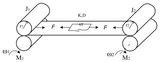
Figure 1.
Two-mass system with elasticity.

Figure 2.
Two-mass system with a stiff shaft.
The parameters in Figure 1 and Figure 2: J1, J2—moment of inertia; M1, M2—torque; r1 and r2 are the roller radii; K, D—coefficient of elasticity and the damping constant of belt material; F—tension force; ω1 and ω2—angular velocity of the first and second mass; M—electromagnetic torque; Mc—load moment.
Mechanical vibrations and torsional oscillations not only strongly affect the operation of drive systems, but also significantly complicate the synthesis of a control system [11,12,13,14,15,16,17]. The problem is especially complicated in resonant and inclined resonant states. The task of a control system, in this case, is not only to ensure achievement and maintenance at a given speed level of the drive mechanism under various perturbations, but also to avoid mechanical oscillations in transients, which can lead to the deterioration of control characteristics. Thus, the identification of the mechanical system state in electric drives is becoming an increasingly important problem [18,19,20].
To describe processes in electric drives with long shafts, which contain complex control devices, the application of shaft models with concentrated mechanical parameters has become widespread. Creation of such models is quite fully described, for example, in [21,22,23]. The shaft is divided into several absolutely rigid inertial links interconnected by means of flexible links. Such a mechanical object is described by ordinary Lagrange differential equations of the second type and is considered a holonomic system with a finite number of degrees of freedom.
A comparison of descriptions of concentrated and distributed parameter systems leads to the conclusion that the description of the distributed parameter systems provides a greater accuracy of modelling and, thus, improves adequacy of temporal and spatial temporal behavior of the functions studied. The question then arises, why not analyze transient states in susceptible motion transmission of electric drives that include long elastic elements by means of boundary or mixed problems? The point is, there is one important requirement in automated electric drives, other than a high model adequacy, namely the relative simplicity of a model, since the solving of boundary problems is quite burdensome.
Fractional-order derivatives and integers are increasingly applied to state-of-the-art approaches to the modelling of processes and electric drives [6,7], which commonly improves model adequacy, or substantially simplifies it, compared to a traditional integral-order model. These approaches are increasingly used in drive control systems [8].
A mathematical model of electric drive, containing a long shaft in its simplified two-mass interpretation, is developed in this paper. To ensure accuracy of the model, the theory of fractional-order calculus is utilized; for instance, the Caputo–Fabrizio operator serves to describe long shaft elastic torque.
The paper additionally shows that the application of such high-accuracy models to synthesis of control systems for industrial electric drives is reasonable when mechanisms requiring high accuracy are studied.
A completely different situation concerns the representation of the object (shaft) as a system with distributed parameters [24,25]; see Figure 3, i.e., with an infinite number of degrees of freedom.
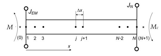
Figure 3.
Long shaft model.
In Figure 3, a diagram of a long shaft with distributed parameters is presented. Let us describe oscillating processes in the long shaft using equations with partial Euler–Poisson derivatives, which, in mathematical terms, is a mixed problem with Dirichlet, Neumann, and Newton’s boundary conditions.
An electromagnetic moment is applied to the left end of the shaft M and to the right load moment Mc. Additional inertial links are also fixed at both ends of the shaft, JEM, JN. Ignoring the external viscous friction, the equation of the long shaft (Figure 3) will be as follows:
where φ—shaft rotation angle; ρ—density of the shaft material; Jp—polar moment of the shaft’s inertia; G—modulus of elasticity of the second type (shear modulus); ξ—coefficient of internal viscous friction.
Boundary conditions for Equation (1) are found on the basis of the d’Alemberta method for two ends of the shaft: equality of driving moments, on the one hand, and dynamic, elastic and dissipative moments, on the other.
Discretizing the system of Equations (1)–(3) with the method of lines produces what is seen in Figure 3:
where N—the discretization nodes number of Equation (1); Δx—discrete of spatial derivatives; j = 0 and j = N + 1—the first and last nodes of spatial derivatives; ω*j—angular speed of j-th section of the shaft; φj—rotation angle of j-th section of the shaft.
As shown in [25], this model adequately reflects the processes in the system and can be used as a reference model in research.
However, taking into account the complexity of the long shaft model with distributed parameters, the model of a two-mass system (with concentrated parameters), such as (5), is traditionally used for the purpose of control system synthesis for electromechanical systems with a long shaft:
where —shaft stiffness factor;—coefficient of internal viscous friction; af1 and af2—external viscous friction factors; and —moments of inertia of the first and second mass, respectively; L—shaft length; M—electromagnetic torque; Mc—moment of the load; M12—elastic moment.
2. Model of a Two-Mass System with Concentrated Parameters
A block diagram of the model of two-mass systems with concentrated parameters is shown in Figure 4. The system equation in the form of state variables will become (6):

Figure 4.
Block diagram of a two-mass system.
After applying the Laplace transformation, the equations for determining the state variables are as follows:
where
In case, when J1 = J2 = J, af1 = af2 = 0 and M = Mc, equations for determining state variables were rewritten as:
and, applying the inverse Laplace transformation, when M = const, we obtain the following system:
We use a system with the following parameters: ρ = 7850 kg/m3; = 8.1 × 10¹⁰ Nm; ξ = 0.5 Nm2; L = 4.5 m; D = 0.05 m; JEM = JN = 20 Nm2; Δx = 0.05 m. A comparative analysis of dependences of change in the velocity of the first mass (Figure 5) as a function of time, obtained using models with distributed and concentrated parameters, suggests that the model with concentrated parameters does not adequately reflect the processes in the system with an elastic shaft. The model with concentrated parameters inadequately addresses the velocity of the mechanical wave, which leads to inaccuracies in determining the actual parameters of the system. In particular, the calculation results in a delay angle δ, which reflects the difference between the real system and its prototype, obtained on the basis of a model with concentrated parameters.
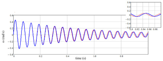
Figure 5.
Speed dependencies: __ model with distributed parameters; __ traditional model of a two-mass system.
Ref. [26] shows that the elastic moment changing in time, in the case of elastic shafts, should be described using fractional derivatives. The value of the fractional order derivative provides modeling of the shaft material properties. When we apply the Caputo–Fabrizio operator to describe the fractional order derivative [27], the equation of the elastic moment is: , after Laplace transformation and if M12(0) equals zero, it will become (10):
Based on (10), the block diagram of the two-mass system will have the form shown in Figure 6.
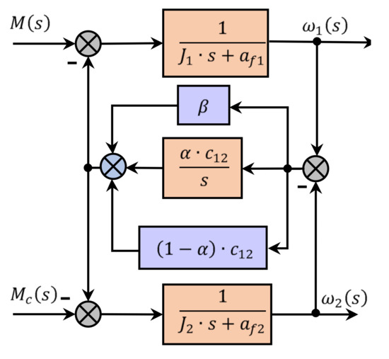
Figure 6.
Block diagram of the two-mass system model when using a fractional order derivative to describe the elastic moment.
Thus, the use of a fractional order derivative to describe the elastic moment, as described in [28], is equivalent to a change (decrease) in stiffness of the shaft and an increase in the coefficient of internal viscous friction β* = β + (1 + α)c12 in the classic two-mass system model. An equivalent model for determining state variables will take the following form (11).
In case J1 = J2 = J, af1 = af2 = 0 and M = Mc, equations for determining state variables will become (12).
and, after applying the inverse Laplace transformation, for M = const, we obtain the following equation for the velocity of the first mass:
where .
Therefore, use of the Caputo–Fabrizio operator to describe the fractional order derivative in the elastic moment model, which is traditionally used to describe electromechanical systems, reduces the oscillation frequency and increases its rate of damping (Figure 7) and, therefore, will inadequately reflect real processes in the system.
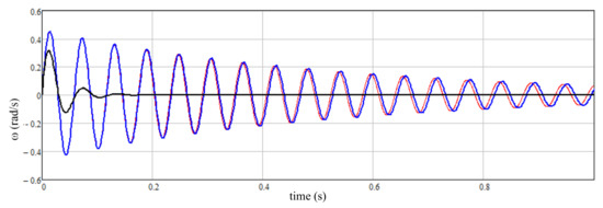
Figure 7.
Speed dependencies: __ model with distributed parameters; __ traditional model of a two-mass system; __ model of a two-mass system using the Caputo–Fabrizio operator to describe of the fractional order derivative in the model of the elastic moment at α = 0.995.
On the other hand, the elastic moment can be defined as
To describe the application of the fractional order integral Caputo–Fabrizio operator [29], the equation of the elastic moment after Laplace transformation can be rewritten as
Based on the expression for the elastic moment (14), the following block diagram of the two-mass system is shown in Figure 8.
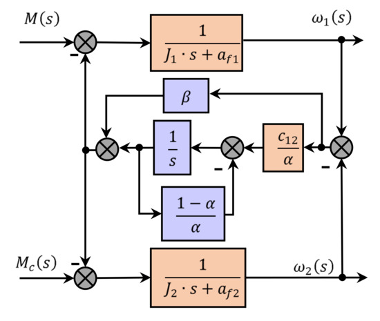
Figure 8.
Block diagram of a two-mass system model when using a fractional integral to describe the elastic moment.
Therefore, the use of a fractional order integral to describe the elastic moment is equivalent to a change (increase) in the shaft’s stiffness and coverage of the integrator in the elastic moment equation by negative feedback with the gain (1 − α)/α in comparison with the classical model of a two-mass system. An equivalent system model for determining state variables will take the form:
and, applying the inverse Laplace transformation, when M = const, pointed
we obtained:
When the value of α ϵ (0.9; 1), given that
We obtained (20):
From (20), use of the Caputo–Fabrizio operator to describe the fractional order integral of the elastic moment in the model leads to an increase in the frequency of oscillations:
with a practically unchanged rate of damping .
As shown in Figure 9, at α = 0.984, the lumped parameters model using integral fractional order to describe the elastic moment provides dependences of the first mass velocity variations, obtained for the reference model with distributed parameters, and therefore adequately describes the processes in the system. α is derived from the equation for the natural frequency of the system when given parameters and experimental results in the application of models with distributed parameters.

Figure 9.
Speed dependencies: __ model with distributed parameters; ooo model of a two-mass system using the Caputo–Fabrizio operator to describe the fractional order derivative in the model of the elastic moment at α = 0.984; xxx—speed calculation, according to the (12) when α = 0.984.
This article analyzes two types of mathematical long shaft models in their two-mass interpretations that address the theory of fractional calculus. The first type is based on a differential representation of shaft elastic torque using the Caputo–Fabrizio operator to describe the fractional-order derivative. The results of a computer simulation are shown in Figure 7. The other type presents elastic torque in an integral format using the same operator to describe the fractional-order integral. The results of a computer simulation are shown in Figure 9. A comparative analysis of the two model types has demonstrated an undoubted superiority of the second-type model, which can be clearly seen in Figure 9, where a virtual convergence of the simulation results in the distributed parameter model and the integral Caputo–Fabrizio model can be noted.
3. Analysis of the Two-Mass System Model
In general, in case of neglecting viscous af1 = af2 = 0, the velocity transfer functions of the first and second mass electromagnetic torque and moment load will be:
To determine the influence of the parameter α on the system model, we use the measure of the distance between the transfer functions [30]:
where
The distance value obtained for the case J1 = J2, between the traditional two-mass model of the system and the model in which the Caputo–Fabrizio operator is used to describe the fractional order integral in the elastic moment equations shows a slight difference between these models. Such a small distance between the models of the system allows for the assumption that choice of a model for the control system parameters synthesis will not have a decisive influence.
4. Synthesis of the Control System
In the case of two-mass systems, full-state control is traditionally used. Information about coordinates that cannot be measured directly is obtained from the system state observer. When control as , the feedback coefficients for the state variables that provide zero compensation system and the desired placement of the roots, as shown in [31], can be found by feedback linearization, synthesized as (25):
where A is the matrix of the system; B1 = (1/J1; 0; 0)T—vector of control influence; C = (0; 0; 1)—a vector that determines the generalized coordinate in the feedback linearization method; ρ—relative degree of the system; is a vector of coefficient that determines the desired location of the roots of a characteristic polynomial.
A two-mass system is characterized, except a control channel u, by the presence of a perturbation channel. In order to compensate for the influence of perturbation, the system should also provide a compensatory effect. The perturbation feedback coefficient at Mc = const is defined [31]:
where B2 = (0; 0; −1/J2)T—vector of control influence. In the traditional model, equations of the feedback coefficients for state variables were described as:
When using a system model with the fractional order integral to describe the elastic moment, the equation for the required coefficients will be as follows:
In the case of a two-mass system model with the fractional order integral in the model of the elastic moment, the closed system transfer functions for full control of the state vector will be as follows:
where
for the coefficients obtained based on the traditional model, and:
where
when applying feedback coefficients for state variables obtained using an improved model.
Taking into account that
The transfer function of a closed system in this case can be rewritten as (32):
The perturbation control factor at Mc = const is equal to and the transfer function of the perturbation system will be as (33):
Our studies concern a model whose parameters are introduced in [31]. Given these parameters, the distance between the transmittances computed from (23) is quite small, as seen in Figure 10. Therefore, the transient characteristics in Figure 11 are quite similar. When precision systems are analyzed, on the other hand, these parameters may differ, which will, in the end, give rise to a difference between the transient characteristics.
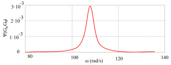
Figure 10.
Change of the distance between the transmittances as a function of angular velocity.
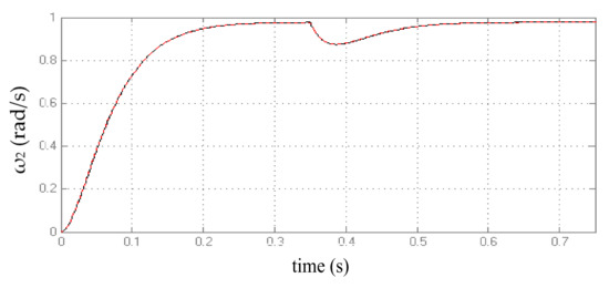
Figure 11.
Transient characteristics and reaction of the system when the load moment changes at t = 0.35 s, by using feedback coefficients synthesized based on: __ traditional model; __ models with a fractional order integral to describe the elastic moment.
The transient characteristics in the case of control synthesized using the traditional and refined models of a two-mass system, when describing the system in the form of a refined model, are shown in Figure 11.
Figure 12 shows the frequency characteristics of open and closed systems. The results confirm the high quality of control of a two-mass system with a long shaft, regardless of the model chosen for synthesis of the control effect.
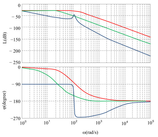
Figure 12.
Bode diagrams of: __ open system; __ closed system by ω0 = 25; __ closed system by ω0 = 125.
5. Conclusions
Based on a comparative analysis of two mathematical models of a long shaft, with distributed and concentrated parameters, we can conclude that the simplified representation of the shaft in the traditional two-mass interpretation does not always fully describe the real processes of generalized coordinates in the system. In particular, it is not possible to take into account the propagation of a mechanical wave along the shaft, which causes the effect of braking the speed movement and shaft rotation angle. As a result, there is a phase shift in the system, and failure to address it leads to inaccuracies. In some cases, it leads to an incorrect value of the time–space distribution of the studied functions, and, thus, to incorrect values of the rotation angles of the drive motor’s rotor and the load mechanism. It is dangerous in precision electric drives with complex control systems, especially for resonant and close to resonant states.
Application of the fractional order integral to the elastic moment modelling made it possible to obtain a refined model of a two-mass system with concentrated parameters. Based on this model, we obtained transient dependences of the long shaft state coordinate variations, which completely coincided with those obtained using the reference mathematical model of the object as a system with distributed parameters.
The frequency domain values obtained measure the distance between the two types of two-mass systems with long shaft models, such as traditional (with integer derivatives) and refined (with fractional derivatives), and transient response control with the full state vector. After analyzing and comparing the synthesized state variable coefficients for both types of models, we conclude that the use of a refined model of the long shaft may be appropriate in complex precision objects. The use of an ordinary object shaft refined model for the synthesis of control actions has virtually no effect on quality control.
We plan to use, in the future, the long shaft improved model for the synthesis of the control system of electric drive for precision mechanisms, including robotic manipulators. Such a model would be used in systems with long elastic links connected to rolls, in mechanisms such as rolling mills, as well as to stabilize the frequency of ship shaft generator drives and for the analysis of impact of drive processes on the quality of such system controls.
Author Contributions
Conceptualization, A.L., A.C., T.P. and A.S.; methodology, A.L., A.C., T.P., A.S. and L.K.; software, A.L. and A.C.; validation, A.L., A.C., T.P., A.S. and L.K.; formal analysis, A.L., A.C., T.P., A.S. and L.K.; investigation, A.L., A.C., T.P., A.S. and L.K.; data curation, A.S. and L.K.; writing—original draft preparation, A.L. and A.C.; writing—review and editing, T.P., A.S. and L.K.; visualization, T.P., A.S. and L.K.; supervision, A.L., A.C., and A.S.; project administration, T.P., A.S. and L.K. All authors have read and agreed to the published version of the manuscript.
Funding
This research received no external funding.
Institutional Review Board Statement
Not applicable.
Informed Consent Statement
Informed consent was obtained from all subjects involved in the study.
Data Availability Statement
Not applicable.
Conflicts of Interest
The authors declare no conflict of interest.
Nomenclature
| parameters and variables | |
| A | matrix of the system |
| af1 | external viscous friction factor of first mass |
| af2 | external viscous friction factor of second mass |
| B1 | vector of control influence of the first mass |
| B2 | vector of control influence of the second mass |
| C | a vector that determines the generalized coordinate |
| c12 | shaft stiffness factor |
| D | the damping constant |
| F | tension force |
| G | modulus of elasticity of the second type (shear modulus) |
| J1 | moment of inertia of first mass |
| J2 | moment of inertia of second mass |
| JEM | inertial link of the first point of shaft |
| JN | inertial link of the end of shaft |
| Jp | polar moment of inertia of the shaft |
| K | coefficient of elasticity |
| kM | the perturbation control factor |
| L | shaft length |
| M1 | torque of first mass |
| M2 | torque of second mass |
| M | electromagnetic torque of the motor |
| Mc | load moment |
| M12 | elastic moment |
| r1 | first roller radius |
| r2 | second roller radius |
| ω1 | angular velocity of the first mass |
| ω2 | angular velocity of the second mass |
| Δx | discrete of spatial derivative |
| α | parameter in Caputo–Fabrizio representation |
| β | coefficient of inertial viscous friction |
| φ | shaft rotation angle |
| ρ | density of the shaft material |
| ξ | coefficient of internal viscous friction |
| ρs | relative degree of the system |
| Indices | |
| j | number of the shaft section |
| N | the number of discretization nodes |
References
- Matsuse, K.; Matsuhashi, D. New technical trends on adjustable speed AC motor drives. Chin. J. Electr. Eng. 2017, 3, 1–9. [Google Scholar]
- Xu, D.; Wang, B.; Zhang, G.; Wang, G.; Yu, Y. A review of sensorless control methods for AC motor drives. Chin. Acad. Sci. Trans. Electr. Mach. Syst. 2018, 2, 104–115. [Google Scholar] [CrossRef]
- Padilla-Garcia, E.A.; Rodriguez-Angeles, A.; ReséNdiz, J.R.; Cruz-Villar, C.A. Concurrent Optimization for Selection and Control of AC Servomotors on the Powertrain of Industrial Robots. IEEE Access 2018, 6, 27923–27938. [Google Scholar] [CrossRef]
- Yu, W.; Huang, Z.; Zhong, C.; Liu, J.; Yuan, Z. Method of Suppressing Torsional Vibration Noise of Automobile Drive-train System Based on Discrete Wavelet. J. Intell. Fuzzy Syst. 2020, 38, 7585–7594. [Google Scholar] [CrossRef]
- Ramírez, G.A.; Valenzuela, M.A.; Pittman, S.; Lorenz, R.D. Modeling and Evaluation of Paper Machine Coater Sections Part 1: 1-Coater Section and Tension Setpoints. IEEE Trans. Ind. Appl. 2019, 55, 2144–2154. [Google Scholar] [CrossRef]
- Arya, P.P.; Chakrabarty, S. A Robust Internal Model-Based Fractional Order Controller for Fractional Order Plus Time Delay Processes. IEEE Control Syst. Lett. 2020, 4, 862–867. [Google Scholar] [CrossRef]
- Yaghooti, B.; Hosseinzadeh, M.; Sinopoli, B. Constrained Control of Semilinear Fractional-Order Systems: Application in Drug Delivery Systems. In Proceedings of the 2020 IEEE Conference on Control Technology and Applications (CCTA), Montreal, QC, Canada, 24–26 August 2020; pp. 833–838. [Google Scholar]
- Yumuk, E.; Güzelkaya, M.; Eksin, I. Optimal fractional-order controller design using direct synthesis method. IET Control Theory Appl. 2020, 14, 2960–2967. [Google Scholar] [CrossRef]
- Wang, Y.; Liu, H.; Liu, H.; Zhao, J. Dynamic analysis and system identification of a synchronous belt mechanism driven by PMSM. In Proceedings of the 2017 3rd IEEE International Conference on Control Science and Systems Engineering (ICCSSE), Beijing, China, 17–19 August 2017; pp. 364–368. [Google Scholar]
- Szabat, K.; Orlowska-Kowalska, T. Adaptive Control of the Electrical Drives with the Elastic Coupling using Kalman Filter. In Adaptive Control; You, K., Ed.; In Tech: Shanghai, China, 2009; pp. 205–226. [Google Scholar]
- Szolc, T.; Konowrocki, R.; Pisarski, D.; Pochanke, A. Influence of Various Control Strategies on Transient Torsional Vibrations of Rotor-Machines Driven by Asynchronous Motors. In International Conference on Rotor Dynamics; Springer: Cham, Switzerland, 2018; Volume 63, pp. 205–220. [Google Scholar]
- Ma, C.; Cao, J.; Qiao, Y. Polynomial-Method-Based Design of Low-Order Controllers for Two-Mass Systems. IEEE Trans. Ind. Electron. 2013, 60, 969–978. [Google Scholar] [CrossRef]
- Lee, D.; Lee, J.H.; Ahn, J. Mechanical vibration reduction control of two-mass permanent magnet synchronous motor using adaptive notch filter with fast Fourier transform analysis. IET Electr. Power Appl. 2012, 6, 455–461. [Google Scholar] [CrossRef]
- Saarakkala, S.E.; Hinkkanen, M. State-Space Speed Control of Two-Mass Mechanical Systems: Analytical Tuning and Experimental Evaluation. IEEE Trans. Ind. Appl. 2014, 50, 3428–3437. [Google Scholar] [CrossRef]
- Cui, J.; Ye, J.; Chu, Z. IP Controller Design for Uncertain Two-Mass Torsional System Using Time Frequency Analysis. Shock Vib. 2018, 1–10. [Google Scholar] [CrossRef]
- Li, W.; Hori, Y. Vibration Suppression Using Single Neuron-Based PI Fuzzy Controller and Fractional-Order Disturbance Observer. IEEE Trans. Ind. Electron. 2007, 54, 117–126. [Google Scholar] [CrossRef]
- Szabat, K.; Orlowska-Kowalska, T. Vibration suppression in a two-mass drive system using PI speed controller and additional feedbacks—Comparative study. IEEE Trans. Ind. Electron. 2007, 54, 1193–1206. [Google Scholar] [CrossRef]
- Nevaranta, N.; Parkkinen, J.; Lindh, T.; Niemela, M.; Pyrhonen, O.; Pyrhonen, J. Online Identification of a Two-Mass System in Frequency Domain using a Kalman Filter. Model. Identif. Control 2016, 37, 133–147. [Google Scholar] [CrossRef]
- Łuczak, D.; Zawirski, K. Parametric identification of multi-mass mechanical systems in electrical drives using nonlinear least squares method. In Proceedings of the IECON 2015—41st Annual Conference of the IEEE Industrial Electronics Society, Yokohama, Japan, 9–12 November 2015; pp. 4046–4051. [Google Scholar]
- Saarakkala, S.; Hinkkanen, M. Identification of Two-Mass Mechanical Systems Using Torque Excitation: Design and Experimental Evaluation. IEEE Trans. Ind. Appl. 2015, 51, 4180–4189. [Google Scholar] [CrossRef]
- Ortega, R.; Loria, A.; Nicklasson, P.J.; Sira-Ramirez, H. Passivity-Beast Control of Euler-Lagrange Systems: Mechanical, Electrical and Electromechanical Applications; Springer: London, UK, 1998; p. 543. [Google Scholar]
- Lukasik, Z.; Czaban, A.; Szafraniec, A. Mathematical model of asynchronous pump drive with distributed mechanical parameters. Prz. Elektrotech. 2018, 94, 155–159. [Google Scholar] [CrossRef]
- Popenda, A.; Lis, M.; Nowak, M.; Blecharz, K. Mathematical modeling of transient states in a drive system with a long elastic element. Energies 2020, 13, 1181. [Google Scholar] [CrossRef]
- Chaban, A. Hamilton-Ostrogradski Principle in Electromechanical Systems; Soroki: Lviv, Ukraine, 2015; p. 488. [Google Scholar]
- Chaban, A.; Lis, M.; Szafraniec, A.; Jedynak, R. Application of Genetic Algorithm Elements to Modelling of Rotation Processes in Motion Transmission Including a Long Shaft. Energies 2021, 14, 115. [Google Scholar]
- Xu, S.; Sun, G.; Cheng, Z. Fractional order modeling and residual vibration suppression for flexible two-mass system. In Proceedings of the 29th Chinese Control and Decision Conference (CCDC), Chongqing, China, 28–30 May 2017; pp. 3658–3664. [Google Scholar]
- Losada, J.; Nieto, J.J. Properties of a new fractional derivative without singular kernel. Prog. Fract. Differ. Appl. 2015, 1, 87–92. [Google Scholar]
- Lozynskyy, A.; Lozynskyy, O.; Kasha, L.; Holovach, I. Analysis of Fractional Derivatives and Integrals Application with Caputo-Fabrizio Operator In Electromechanical Systems. In Proceedings of the 2020 IEEE 21st International Conference on Computational Problems of Electrical Engineering (CPEE), Online Conference, Poland, 16–19 September 2020; pp. 1–4. [Google Scholar]
- Mboro Nchama, G.A.; Mecıas, A.L.; Richard, M.R. The Caputo-Fabrizio Fractional Integral to Generate Some New Inequalities. Inf. Sci. Lett. 2019, 8, 73–80. [Google Scholar]
- Vinnicombe, G. Frequency domain uncertainty and the graph topology. IEEE Trans. Autom. Control 1993, 38, 1371–1383. [Google Scholar] [CrossRef]
- Lozynskyy, A.; Marushchak, Y.; Lozynskyy, O.; Kasha, L. Synthesis of Combine Feedback Control of Electromechanical System by Feedback Linearization Method. In Proceedings of the 2020 IEEE Problems of Automated Electrodrive, Theory and Practice (PAEP), Kremenchuk, Ukraine, 21–25 September 2020; pp. 1–6. [Google Scholar]
Publisher’s Note: MDPI stays neutral with regard to jurisdictional claims in published maps and institutional affiliations. |
© 2021 by the authors. Licensee MDPI, Basel, Switzerland. This article is an open access article distributed under the terms and conditions of the Creative Commons Attribution (CC BY) license (http://creativecommons.org/licenses/by/4.0/).