Article

Passive Model Predictive Control on a Two-Body Self-Referenced Point Absorber Wave Energy Converter

1
Department of Electric Power Engineering, Norwegian University of Science and Technology NTNU, Elektrobygget O.S. Bragstads Plass 2E, E, 3rd Floor, 7034 Trondheim, Norway
2
Department of Industrial Engineering, University of Trento, Via Sommarive 9, 38123 Trento, Italy
3
UMBRAGROUP SpA, Via V. Baldaccini 1, 06034 Foligno, Italy
4
K2 Management, Rua do Montepio Geral, N 4 A 1500-465 Lisboa, Portugal
*
Author to whom correspondence should be addressed.
Energies 2021, 14(6), 1731; https://doi.org/10.3390/en14061731
Submission received: 11 February 2021 / Revised: 13 March 2021 / Accepted: 16 March 2021 / Published: 20 March 2021
(This article belongs to the Section A3: Wind, Wave and Tidal Energy)

Abstract

:
Wave energy is nowadays one of the most promising renewable energy sources; however, wave energy technology has not reached the fully-commercial stage, yet. One key aspect to achieve this goal is to identify an effective control strategy for each selected Wave Energy Converter (WEC), in order to extract the maximum energy from the waves, while respecting the physical constraints of the device. Model Predictive Control (MPC) can inherently satisfy these requirements. Generally, MPC is formulated as a quadratic programming problem with linear constraints (e.g., on position, speed and Power Take-Off (PTO) force). Since, in the most general case, this control technique requires bidirectional power flow between the PTO system and the grid, it has similar characteristics as reactive control. This means that, under some operating conditions, the energy losses may be equivalent, or even larger, than the energy yielded. As many WECs are designed to only allow unidirectional power flow, it is necessary to set nonlinear constraints. This makes the optimization problem significantly more expensive in terms of computational time. This work proposes two MPC control strategies applied to a two-body point absorber that address this issue from two different perspectives: (a) adapting the MPC formulation to passive loading strategy; and (b) adapting linear constraints in the MPC in order to only allow an unidirectional power flow. The results show that the two alternative proposals have similar performance in terms of computational time compared to the regular MPC and obtain considerably more power than the linear passive control, thus proving to be a good option for unidirectional PTO systems.

1. Introduction

Ocean energy and particularly wave energy is nowadays one of the most promising, but still underutilized, renewable energy sources that can be commercially exploited to provide power to the electrical grid [1]. One key aspect to achieve this goal is an efficient control strategy which absorbs maximum energy from the waves, while respecting the physical constraints of each WEC.
Linear control strategies are still the most used for WECs. They have been deeply studied in the WEC literature and provide a reliable, robust and efficient control in most cases. Among them, in reactive control the force applied by the PTO system is the sum of multiple components, proportional to the position, velocity, and acceleration of the WEC, respectively [2]. This strategy typically requires the PTO to be oversized and work both as generator and motor, which can have a negative impact on its efficiency [3]. In reactive control, the optimal velocity profile is a function of the future wave excitation force; thus, this velocity cannot be determined optimally in practice. For this reason, suboptimal control strategies based on causal functions are used [4]. Moreover, reactive control presents drawbacks from the energy perspective, requiring large bidirectional power flows between the WEC and the PTO [5]. In addition, displacements and velocities may be too high and would have to be considered in the mechanical design and managed in the WEC operation.
Passive control is another strategy where the force applied by the PTO is just proportional to the WEC velocity, which allows a unidirectional power exchange, from the WEC to the PTO. Compared to reactive control, passive control presents the following advantages: (a) unidirectional instead of bidirectional power flow means moderate losses; and (b) the power peaks and the amplitude of the oscillations are lower, so the installation becomes cheaper and less critical. The main passive control drawback is the limited power capture compared to reactive, especially for wave profiles far from the natural response of the WEC.
The Model Predictive Control (MPC) is being used with certain success on Wave Energy Converters, because its formulation is optimal in terms of energy extraction and is able to inherently manage physical constraints [6,7]. This technique requires a WEC model and an excitation force prediction within a predefined time interval in order to predict the next control action on the PTO force [8]. This action is obtained optimizing an objective function over the prediction horizon. Generally, MPC on WEC applications is formulated as a quadratic programming (QP) problem with linear constraints, where the objective function is the extracted energy and the constraints are the position, speed and PTO force [9,10]. Since in the most general case this control technique requires bidirectional power flow between the PTO system and the grid, it has similar disadvantages as reactive control: (a) PTO working as generator and motor; (b) increase of PTO losses; and (c) reduction of efficiency.
Few MPC applications to WECs have addressed the problem of restricting the power flow direction from the WEC to the PTO, thus allowing its application to a broader range of existing WECs. The reason for this gap is that allowing this unidirectional energy flow using QP in MPC requires setting nonlinear constraints. This turns the QP optimization with linear constraints into a Nonlinear Programming (NLP) problem with nonlinear constraints, making the computational effort significantly higher [6]. Among the few contributions addressing the problem in the available literature, O’Sullivan and Lightbody [11] restricted the power flow direction by means of a nonlinear constraint function that depends on the speed, flux, resistance and current of an electrical PTO. To allow just unidirectional power flow, Paparella and Ringwood [12,13] proposed a MPC-like strategy using pseudo-spectral control with truncated Fourier series as orthogonal base to handle the nonlinear power constraints in a more efficient way. Both proposals have, however, the same drawback: nonlinear constraints imply higher processing time to solve the optimization problem. Tom and Yeung [14] studied a permanent magnet generator as PTO with a passive non-linear MPC control strategy. They defined the PTO force as a linear function of the velocity (F p t o = b g v(t)) and integrated the dynamic of the WEC inside the objective function from a numerical perspective using the Berkeley Library for Optimization Modeling software (BLOM) on a Matlab/Simulink (version 2012, Berkeley, CA, USA) model. This work proposes two independent MPC control strategies applied to a two-body self-reference point absorber that address this issue from two different perspectives: (a) adapting the MPC formulation to achieve passive loading strategy similar to the work by Tom and Yeung [14], but integrating analytically the dynamic of the WEC inside the objective function; and (b) re-formulating the linear constraints in the MPC in order to only allow an unidirectional energy flow. The results show that the proposed control strategies have similar performance compared to the regular MPC in terms of computational time, and they extract considerably more power than the classical passive control.
This rest of the paper is divided into six sections. Section 2 presents the model of the two-body self-reference point absorber. Section 3 shows the traditional MPC approach considering linear and nonlinear constraints. The two MPC proposals based on passivity (to prevent bidirectional energy flow) are formulated in Section 4 and Section 5, respectively. Section 6 presents the analysis of the results. Section 7 draws the conclusions.

2. Model of the Two-Body Self-Reference Point Absorber WEC

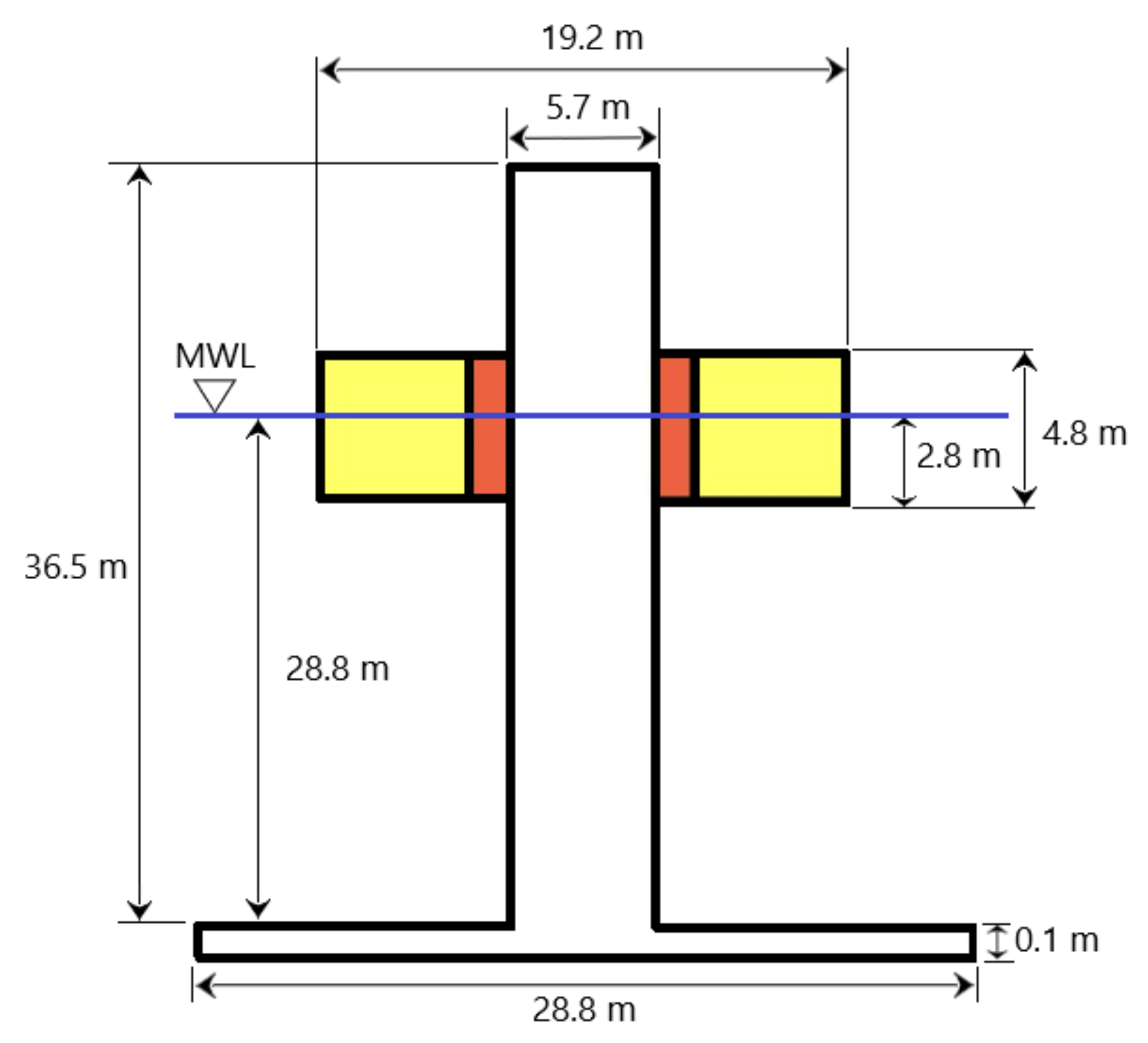
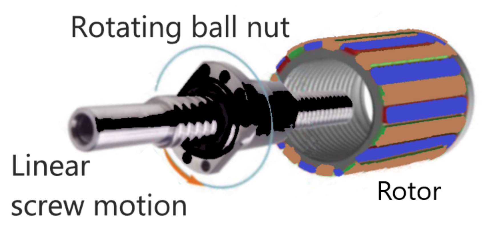
The WEC model used in this work, as shown in Figure 1, was developed within the IMAGINE project [15] funded by the European Union’s Horizon 2020 programme. This WEC is a two-body self-referenced point absorber formed by an external floater ring that moves with respect to an internal cylindrical spar attached to the seabed by means of a mooring. This relative movement is exploited by the PTO to extract power from the WEC. The PTO system is a direct-drive device in which a recirculating ball screw is coupled with a three-phase Permanent Magnet Generator (PMG), as shown in Figure 2 [16] and described in [17]. The linear motion of the ball screw is converted into the nut rotary motion. Being the ball nut connected to the rotor of the permanent magnet generator, its mechanical rotational energy is directly converted in electricity.
Linear wave theory was used to model the wave profile. According to the Cumming’s formulation, the dynamic Equations (1) and (2) describe the two-body wave energy converter motion in heave mode [18]:
( m 1 + A 11 ) z ¨ 1 ( t ) + F r 1 ( t ) + k h 1 z 1 ( t ) + ( b f r + b v 1 ) z ˙ 1 ( t ) b f r z ˙ 2 ( t ) = F e 1 ( t ) + F p t o ( t )
( m 2 + A 22 ) z ¨ 2 ( t ) + F r 2 ( t ) + ( k h 2 + k m ) z 2 ( t ) + ( b f r + b v 2 ) z 2 ˙ ( t ) b f r z ˙ 1 ( t ) = F e 2 ( t ) F p t o ( t )
where ρ is the water density, g is the gravity acceleration, k m is the mooring stiffness, b f r is the PTO friction coefficient and F p t o ( t ) is the PTO force. For body i, k h i = ρ g S i is the hydrostatic coefficient, m i is the mass, S i is the body transversal area, b v i is the viscosity coefficient, A i i is the added mass at infinite frequency, F r i ( t ) is the radiation force, F e i ( t ) is the excitation force and z i ( t ) , z ˙ i ( t ) and z ¨ i ( t ) are the position, speed, and acceleration. In the paragraph above, the subscript i is 1 when referred to Body 1 (floater) and 2 when referred to Body 2 (spar). In addition, the PTO mass is considered negligible compared to m 1 and m 2 .

2.1. Space State Model in Continuous Time

Both radiation forces F r 1 ( t ) and F r 2 ( t ) above can be modeled by means of state space equations based on the work of Falnes and Yu [19]. The space state models used for the floater and the spar are the following third- and second-order systems, respectively:
U ˙ 1 ( t ) = A r 1 U 1 ( t ) + B r 1 z ˙ 1 ( t )
F r 1 ( t ) = C r 1 U 1 ( t )
where
A r 1 = a r 1 ( 1 , 1 ) a r 1 ( 1 , 2 ) a r 1 ( 1 , 3 ) a r 1 ( 2 , 1 ) a r 1 ( 2 , 2 ) a r 1 ( 2 , 3 ) a r 1 ( 3 , 1 ) a r 1 ( 3 , 2 ) a r 1 ( 3 , 3 ) B r 1 = b r 1 ( 1 ) b r 1 ( 2 ) b r 1 ( 3 ) U 1 ( t ) = u 11 ( t ) u 21 ( t ) u 31 ( t )
C r 1 ( t ) = c r 1 ( 1 ) c r 1 ( 2 ) c r 1 ( 3 )
and
U ˙ 2 ( t ) = A r 2 U 2 ( t ) + B r 2 z ˙ 2 ( t )
F r 2 ( t ) = C r 2 U 2 ( t )
where
A r 2 = a r 2 ( 1 , 1 ) a r 2 ( 1 , 2 ) a r 2 ( 2 , 1 ) a r 2 ( 2 , 2 ) B r 2 = b r 2 ( 1 ) b r 2 ( 2 ) U 2 ( t ) = u 12 ( t ) u 22 ( t )
C r 2 = c r 2 ( 1 ) c r 2 ( 2 )
The states of the radiation forces F r 1 ( t ) and F r 2 ( t ) are U 1 ( t ) = [ u 11 ( t ) u 21 ( t ) u 31 ( t ) ] T and U 2 ( t ) = [ u 12 ( t ) u 22 ( t ) ] T , respectively. The dynamics described by the system of differential equations from (1) to (10) can be modeled by means of the following state space equations [18,19]:
X ˙ ( t ) = A X ( t ) + B e 1 F e 1 ( t ) + B e 2 F e 2 ( t ) + B p t o F p t o ( t )
Y ( t ) = C X ( t ) = [ z 1 ( t ) z 2 ( t ) z 1 ˙ ( t ) z 2 ˙ ( t ) ] T
where
X ( t ) = [ u 11 ( t ) u 21 ( t ) u 31 ( t ) z 1 ( t ) z 1 ˙ ( t ) u 12 ( t ) u 22 ( t ) z 2 ( t ) z 2 ˙ ( t ) ] T
A = a r 1 ( 1 , 1 ) a r 1 ( 1 , 2 ) a r 1 ( 1 , 3 ) 0 b r 1 ( 1 ) 0 0 0 0 a r 1 ( 2 , 1 ) a r 1 ( 2 , 2 ) a r 1 ( 2 , 3 ) 0 b r 1 ( 2 ) 0 0 0 0 a r 1 ( 3 , 1 ) a r 1 ( 3 , 2 ) a r 1 ( 3 , 3 ) 0 b r 1 ( 3 ) 0 0 0 0 0 0 0 0 1 0 0 0 0 c r 1 ( 1 ) A 1 c r 1 ( 2 ) A 1 c r 1 ( 3 ) A 1 k h 1 A 1 b v 1 + b f r A 1 0 0 0 b f r A 1 0 0 0 0 0 a r 2 ( 1 , 1 ) a r 2 ( 1 , 2 ) 0 b r 2 ( 1 ) 0 0 0 0 0 a r 2 ( 2 , 1 ) a r 2 ( 2 , 2 ) 0 b r 2 ( 2 ) 0 0 0 0 0 0 0 0 1 0 0 0 0 b f r A 2 c r 2 ( 1 ) A 2 c r 2 ( 2 ) A 2 k h 2 + k m A 2 b f r + b v 2 A 2
B e 1 = 0 0 0 0 1 A 1 0 0 0 0 T
B e 2 = 0 0 0 0 0 0 0 0 1 A 2 T
B p t o = 0 0 0 0 1 A 1 0 0 0 1 A 2 T
C = 0 0 0 1 0 0 0 1 0 0 0 0 0 1 0 0 0 1
and A 1 = ( m 1 + A 11 ) , A 2 = ( m 2 + A 22 ) , z 1 ( t ) z 2 ( t ) is the position of the PTO and z 1 ˙ ( t ) z 2 ˙ ( t ) is its velocity. Numerical values of the WEC parameters present from Equation (3) to (18) can be found in Appendix A.

2.2. Space State Model in Discrete Time

To design an MPC strategy, the discretization of the space state model is necessary. In this section, two space state models in discrete time are presented. The first one uses the discretized PTO force, F p t o ( k ) (where k is the discretized time variable), as control signal and the second uses the variation of the discretized PTO force between successive time instants, Δ F p t o ( k + 1 ) = F p t o ( k + 1 ) F p t o ( k ) including the PTO force, F p t o ( k ) , as a system state. Both approaches are equivalent and are used as needed by the proposals. The first approach makes it easy to rewrite the control variable F p t o ( k ) by b p t o ( z 1 ˙ ( t ) z 2 ˙ ( t ) ) in order to formulate a first passive MPC strategy as a function of the b p t o parameter. The second MPC approach allows constraining the variation of the PTO force between time steps and at the same time assign the linear constraints on the state variables speed and PTO force.

2.2.1. First Approach: PTO Force F p t o ( k ) as Control Signal

Using the discrete solution of the state space in Equation (11) described by Chen [20] and considering the variables constant between samples, in the zero-order hold approximation, the following discrete state space equation is obtained:
X ( k + 1 ) = A d X ( k ) + B d e 1 F e 1 ( k ) + B d e 2 F e 2 ( k ) + B d p t o F p t o ( k )
Y ( k ) = C d X ( k ) = [ z 1 ( k ) z 2 ( k ) z 1 ˙ ( k ) z 2 ˙ ( k ) ] T
where A d = e A T , B d e 1 = A 1 ( e A T I ) B e 1 , B d e 2 = A 1 ( e A T I ) B e 2 , B d p t o = A 1 ( e A T I ) B p t o , C d = C , F p t o ( k ) is the discretized PTO force, F e 1 ( k ) and F e 2 ( k ) are the discretized excitation forces on both floater and spar and X ( k ) is the discretized state vector:
X ( k ) = [ y 11 ( k ) y 21 ( k ) y 31 ( k ) z 1 ( k ) z 1 ˙ ( k ) y 12 ( k ) y 22 ( k ) z 2 ( k ) z 2 ˙ ( k ) ] T

2.2.2. Second Approach: Variation of the PTO Force Δ F p t o ( k ) as Control Signal

Cretel et al. [21] rewrote the discrete state space formulation of Equation (19) including the excitation forces and the PTO force as states. In addition, incremental values of the excitation forces Δ F e 1 ( k + 1 ) , Δ F e 2 ( k + 1 ) and PTO force Δ F p t o ( k + 1 ) are the new inputs (Equations (22)–(24)).
F e 1 ( k + 1 ) = F e 1 ( k ) + Δ F e 1 ( k + 1 )
F e 2 ( k + 1 ) = F e 2 ( k ) + Δ F e 2 ( k + 1 )
F p t o ( k + 1 ) = F p t o ( k ) + Δ F p t o ( k + 1 )
The state space equations in terms of the new augmented state vector are:
W ( k + 1 ) = A w . W ( k ) + B w 1 . Δ F e 1 ( k + 1 ) + B w 2 . Δ F e 2 ( k + 1 ) + B wpto . Δ F p t o ( k + 1 )
V ( k ) = C w . W ( k )
where
W ( k ) = X ( k ) F e 1 ( k ) F e 2 ( k ) F p t o ( k ) , V ( k ) = z 1 ( k ) z 2 ( k ) z 1 ˙ ( k ) z 2 ˙ ( k ) F p t o ( k )
A w = A d B d e 1 B d e 2 B d p t o 0 1 , 9 1 0 0 0 1 , 9 0 1 0 0 1 , 9 0 0 1 , B w 1 = 0 9 , 1 1 0 0 , B w 2 = 0 9 , 1 0 1 0
B wpto = 0 9 , 1 0 0 1 , C w = C d 0 2 , 1 0 2 , 1 0 2 , 1 0 1 , 9 0 0 1
and 0 x , y is a null elements matrix with x rows and y columns.
Setting the incremental values of the PTO force Δ F p t o ( k + 1 ) as a control signal allows avoiding abrupt changes in the PTO force between consecutive control actions using an additional linear constraint in the MPC optimization problem. This new constraint is explained in Section 3.3.

3. Traditional Model Predictive Control

MPC gets an optimal control for optimizing an objective function (minimization or maximization) over a finite future time horizon. To implement an MPC strategy successfully, the following are necessary [22]: (a) a mathematical model of the system to predict the output on the future horizon; (b) an objective function to obtain an optimal control series over the future horizon using an optimization procedure with constraints; and (c) a receding strategy where, at each instant, the first sample of the optimal control series calculated by the optimization is applied.

3.1. Prediction Equations of the Traditional MPC

To get the prediction equations, the methodology shown by Rossiter [23] is used. This methodology is based on the discrete state space in Equation (25) obtained by assuming the variation of the PTO force Δ F p t o ( k ) between two consecutive time instants as the control signal (second approach in Section 2.2):
V ( k ) = P W ( k ) + H e 1 Δ F e 1 ( k ) + H e 2 Δ F e 2 ( k ) + H pto Δ F pto ( k )
where
Δ F e 1 ( k ) = Δ F e 1 ( k + 1 ) Δ F e 1 ( k + 2 ) Δ F e 1 ( k + 3 ) Δ F e 1 ( k + n h ) , Δ F e 2 ( k ) = Δ F e 2 ( k + 1 ) Δ F e 2 ( k + 2 ) Δ F e 2 ( k + 3 ) Δ F e 2 ( k + n h ) , Δ F pto ( k ) = Δ F p t o ( k + 1 ) Δ F p t o ( k + 2 ) Δ F p t o ( k + 3 ) Δ F p t o ( k + n h )
V ( k ) = V ( k + 1 ) V ( k + 2 ) V ( k + 3 ) V ( k + n h ) = ( z 1 ( k + 1 ) z 2 ( k + 1 ) , z 1 ˙ ( k + 1 ) z 2 ˙ ( k + 1 ) , F p t o ( k + 1 ) ) T ( z 1 ( k + 2 ) z 2 ( k + 2 ) , z 1 ˙ ( k + 2 ) z 2 ˙ ( k + 2 ) , F p t o ( k + 2 ) ) T ( z 1 ( k + 3 ) z 2 ( k + 3 ) , z 1 ˙ ( k + 3 ) z 2 ˙ ( k + 3 ) , F p t o ( k + 3 ) ) T ( z 1 ( k + n h ) z 2 ( k + n h ) , z 1 ˙ ( k + n h ) z 2 ˙ ( k + n h ) , F p t o ( k + n h ) ) T
P = C w A w C w A w 2 C w A w 3 C w A w n h
H e 1 = C w B w 1 0 3 , 1 0 3 , 1 0 3 , 1 C w A w B w 1 C w B w 1 0 3 , 1 0 3 , 1 C w A w 2 B w 1 C w A w B w 1 C w B w 1 0 3 , 1 C w A w n h 1 B w 1 C w A w n h 2 B w 1 C w A w n h 3 B w 1 C w B w 1
H e 2 = C w B w 2 0 3 , 1 0 3 , 1 0 3 , 1 C w A w B w 2 C w B w 2 0 3 , 1 0 3 , 1 C w A w 2 B w 2 C w A w B w 2 C w B w 2 0 3 , 1 C w A w n h 1 B w 2 C w A w n h 2 B w 2 C w A w n h 3 B w 2 C w B w 2
H pto = C w B wpto 0 3 , 1 0 3 , 1 0 3 , 1 C w A w B wpto C w B wpto 0 3 , 1 0 3 , 1 C w A w 2 B wpto C w A w B wpto C w B wpto 0 3 , 1 C w A w n h 1 B wpto C w A w n h 2 B wpto C w A w n h 3 B wpto C w B wpto
and n h is the sample number of the prediction horizon.

3.2. Objective Function of the Traditional MPC Control

The objective function J ( k ) to be minimized at each time instant, k, is the opposite of the average power absorbed by the PTO over the prediction horizon.
J ( k ) = 1 n h i = 1 n h F p t o ( k + i ) ( z ˙ 1 ( k + i ) z ˙ 2 ( k + i ) )
The objective function above can be rewritten in terms of the future output V ( k ) of Equation (27).
J ( k ) = 1 2 V ( k ) T Q 1 V ( k )
where Q 1 is the following square matrix with order 3 n h .
Q 1 = M 0 3 , 3 0 3 , 3 0 3 , 3 M 0 3 , 3 0 3 , 3 0 3 , 3 M
with
M 1 = 0 0 0 0 0 1 0 1 0
Finally, substituting Equation (27) into Equation (35), the following MPC objective function of a typical quadratic programming problem is obtained:
J = 1 2 Δ F pto ( k ) T H pto T Q 1 H pto Δ F pto ( k ) + ( P W ( k ) + H e 1 Δ F e 1 ( k ) + H e 2 Δ F e 2 ( k ) ) T Q 1 H pto Δ F pto ( k ) )

3.3. Constraints on the Objective Function for the Traditional MPC

To set maximum and minimum values to the force, velocity, position and force increment of the PTO, linear constraints on the MPC objective function can be added to the optimization problem [7]. Restrictions on the PTO force increments can be simply formulated as:
Δ F pto m i n < Δ F pto ( k ) < Δ F pto m a x
On the other hand, constraints on the position, speed and PTO force can be set in the prediction vector V ( k ) (Equation (29)) and expressed by means of Equation (27) as a linear matrix relationship as a function of the control variable Δ F pto ( k ) :
V ( k ) m i n P W ( k ) H e 1 Δ F e 1 ( k ) H e 2 Δ F e 2 ( k ) < H pto Δ F pto ( k ) <
V ( k ) m a x P W ( k ) H e 1 Δ F e 1 ( k ) H e 2 Δ F e 2 ( k )
Regarding the restrictions defined in Equations (39) and (40), the optimization problem of Equation (38) becomes a quadratic programming problem with linear constraints.

3.4. Non-Linear Constraints on the Objective Function for the Traditional MPC to Get Passivity

A direct way to get unidirectional power flow in the MPC optimization problem of the Equation (38) is constraining the PTO power at each instant by means of the product between PTO force and velocity [11]. However, as mentioned in Section 1, this approach is expensive in terms of computational time, hence it provides a solution to the passivity problem that is not viable for real-time applications, thus limiting its practical usability. In the following, the PTO power constraint is enforced at each time instant, k, by means of the product between PTO force and velocity:
P p t o ( k + i ) = F p t o ( k + i ) ( z ˙ 1 ( k + i ) z ˙ 2 ( k + i ) ) > 0 f o r i = 1 , 2 , n h
The MPC objective function of Equation (38) and the non-linear constraint of Equation (41) define a nonlinear programming problem (NLP) with nonlinear constraints.

4. Passive MPC Proposal 1: Adapting MPC Formulation to Passive Loading Strategy

One of the passive control strategies is the resistive load control where the PTO force just depends on the PTO velocity in the following linear way:
F p t o ( t ) = b p t o ( z ˙ 1 ( t ) z ˙ 2 ( t ) )
To constraint the PTO force to take values such that the control is passive, Equation (42) is discretized and substituted in the discrete model of Equation (19), which was obtained by using the PTO force F p t o ( k ) as the control signal (first approach in Section 2.2):
X ( k + 1 ) = A d X ( k ) + B d e 1 F e 1 ( k ) + B d e 2 F e 2 ( k ) + B d p t o b p t o ( z ˙ 1 ( k ) z ˙ 2 ( k ) )
The last term in Equation (43) can be expressed using the state space vector X ( k ) . From Equation (21):
z ˙ 1 ( k ) z ˙ 2 ( k ) = B f X ( k )
where
B f = 0 0 0 0 1 0 0 0 1
Finally, the discrete space state model can be formulated as:
X ( k + 1 ) = A d 2 X ( k ) + B d e 1 F e 1 ( k ) + B d e 2 F e 2 ( k )
Y ( k ) = C d X ( k ) = [ z 1 ( k ) z 2 ( k ) z 1 ˙ ( k ) z 2 ˙ ( k ) ] T
where
A d 2 = A d + B d p t o b p t o B f
Notice that matrix A d 2 is function of b p t o . Equations (46) and (47) model a two-body point absorber with passive control in discrete time, where the PTO damping is defined by b p t o .

4.1. Prediction Equations of the Passive MPC Proposal 1

The main idea of this passive MPC proposal is to determine the PTO damping at each time instant, k, for the WEC modeled by Equations (46) and (47). This means that:
b p t o = b p t o ( k )
To do so, an optimization problem is formulated using the discrete system model of Equations (46) and (47) and prediction of the excitation forces on a future horizon. Based on the discrete state space in Equations (46) and (47) and using the methodology shown by Rossiter [23], the following prediction equations for the passive MPC formulation can be obtained:
Y ( k ) = P X ( k ) + H e 1 F e 1 ( k ) + H e 2 F e 2 ( k )
where
F e 1 ( k ) = F e 1 ( k + 1 ) F e 1 ( k + 2 ) F e 1 ( k + 3 ) F e 1 ( k + n h ) , F e 2 ( k ) = F e 2 ( k + 1 ) F e 2 ( k + 2 ) F e 2 ( k + 3 ) F e 2 ( k + n h ) , Y ( k ) = Y ( k + 1 ) Y ( k + 2 ) Y ( k + 3 ) Y ( k + n h ) , P = C d A d 2 C d A d 2 2 C d A d 2 3 C d A d 2 n h
H e 1 = C d B de 1 0 3 , 1 0 3 , 1 0 3 , 1 C d A d 2 B de 1 C d B de 1 0 3 , 1 0 3 , 1 C d A d 2 2 B de 1 C d A d 2 B de 1 C d B de 1 0 3 , 1 C d A d 2 n h 1 B de 1 C d A d 2 n h 2 B de 1 C d A d 2 n h 3 B de 1 C d B de 1
H e 2 = C d B de 2 0 3 , 1 0 3 , 1 0 3 , 1 C d A d 2 B de 2 C d B de 2 0 3 , 1 0 3 , 1 C d A d 2 2 B de 2 C d A d 2 B de 2 C d B de 2 0 3 , 1 C d A d 2 n h 1 B de 2 C d A d 2 n h 2 B de 2 C d A d 2 n h 3 B de 2 C d B de 2
Notice that the matrices P , H e 1 and H e 2 in Equations (50)–(53) depend on A d 2 , which is function of b p t o ( k ) (Equations (48)–(49)). It means that these matrices change in each time instant, k, as b p t o ( k ) changes.

4.2. Objective Function of the Passive MPC Proposal 1

In passive control, the opposite of the average power absorbed at each time instant, k, by the PTO over the prediction horizon can be formulated as:
J ( k ) = 1 n h i = 1 n h b p t o ( k + i ) ( z ˙ 1 ( k + i ) z ˙ 2 ( k + i ) ) 2
Equation (54) can be rewritten in term of the future output Y ( k ) from Equation (50).
J ( k ) = b p t o ( k ) n h Y ( k ) T Q 2 Y ( k )
where Q 2 is the following square matrix with order 2 n h .
Q 2 = M 0 2 , 2 0 2 , 2 0 2 , 2 M 0 2 , 2 0 2 , 2 0 2 , 2 M
with
M 2 = 0 0 0 1
Substituting Equation (50) into Equation (55) and considering the dependence of P , H e 1 and H e 2 on b p t o ( k ) , the objective function of Equation (54) can be expressed as:
J ( k ) = b p t o ( k ) P [ b p t o ( k ) ] X ( k ) + H e 1 [ b p t o ( k ) ] F e 1 ( k ) + H e 2 [ b p t o ( k ) ] F e 2 ( k ) T . Q P [ b p t o ( k ) ] X ( k ) + H e 1 [ b p t o ( k ) ] F e 1 ( k ) + H e 2 [ b p t o ( k ) ] F e 2 ( k )
where at each time instant, k, the only unknown variable to be determined is the PTO damping b p t o ( k ) . The optimization problem of the Equation (58) is a one-variable NLP without constraint.

4.3. Constraints on the Objective Function of the Passive MPC Proposal 1

Although there is no constraint in the optimization of the objective function given in Equation (58), the positive sign of b p t o ( k ) at each time instant k should be verified.

5. Passive MPC Proposal 2: Adapting Linear Constraints in the MPC to Get Passivity

This passive MPC proposal uses the same objective function as the traditional MPC (Equation (38)). Unlike the first proposal in Section 4, which determines PTO damping b p t o ( k ) at each time instant, this MPC optimization problem leads to estimate a PTO force series over the prediction horizon at each time instant. Passive control is imposed by properly managing the linear constraints defined in Equations (39) and (40). The idea is to define speed and PTO force constraints at each time instant over the prediction horizon in such way that the product between speed and PTO force is positive.

5.1. Prediction Equations of the Passive MPC Proposal 2

This proposal uses the same prediction Equation (27) as the traditional MPC.

5.2. Objective Function of the Passive MPC Proposal 2

This proposal uses the same objective function Equation (38) as the traditional MPC.

5.3. Constraints on the Objective Function of the Passive MPC Proposal 2

Linear constraints in the traditional MPC (Equation (40)) allow estimating PTO force increments Δ F pto ( k ) over the prediction horizon, limiting the variation range of the position ( x p t o m i n , x p t o m a x ), velocity ( v p t o m i n , v p t o m a x ) and force of the PTO ( F p t o m i n , F p t o m a x ) by setting maximum and minimum values in the vector V ( k ) (Equation (29)). Generally, these limits are constants over the prediction horizon and for all time instants k, hence, the elements of the vectors V ( k ) m i n and V ( k ) m a x defined in Equation (40) are:
V ( k ) m a x = ( x p t o m a x , v p t o m a x , F p t o m a x ) T ( x p t o m a x , v p t o m a x , F p t o m a x ) T ( x p t o m a x , v p t o m a x , F p t o m a x ) T ( x p t o m a x , v p t o m a x , F p t o m a x ) T , V ( k ) m i n = ( x p t o m i n , v p t o m i n , F p t o m i n ) T ( x p t o m i n , v p t o m i n , F p t o m i n ) T ( x p t o m i n , v p t o m i n , F p t o m i n ) T ( x p t o m i n , v p t o m i n , F p t o m i n ) T
To set a passive MPC strategy that handles the linear constraints, maximum and minimum values of Equation (59) must be considered as variants over the prediction horizon and for every time instant k:
V ( k ) m a x = ( x p t o m a x ( k + 1 ) , v p t o m a x ( k + 1 ) , F p t o m a x ( k + 1 ) ) T ( x p t o m a x ( k + 2 ) , v p t o m a x ( k + 2 ) , F p t o m a x ( k + 2 ) ) T ( x p t o m a x ( k + 3 ) , v p t o m a x ( k + 3 ) , F p t o m a x ( k + 3 ) ) T ( x p t o m a x ( k + n h ) , v p t o m a x ( k + n h ) , F p t o m a x ( k + n h ) ) T
V ( k ) m i n = ( x p t o m i n ( k + 1 ) , v p t o m i n ( k + 1 ) , F p t o m i n ( k + 1 ) ) T ( x p t o m i n ( k + 2 ) , v p t o m i n ( k + 2 ) , F p t o m i n ( k + 2 ) ) T ( x p t o m i n ( k + 3 ) , v p t o m i n ( k + 3 ) , F p t o m i n ( k + 3 ) ) T ( x p t o m i n ( k + n h ) , v p t o m i n ( k + n h ) , F p t o m i n ( k + n h ) ) T
The idea is to find values to the elements of the matrices in Equations (60) and (61) that impose unidirectional power flow on the PTO. Traditional passive control can provide these values in a fast way. Following, a generic set of PTO velocities v p t o r e f ( k ) and PTO forces F p t o r e f ( k ) obtained by applying passive control ( F p t o r e f ( k ) = b p t o v p t o r e f ( k ) ) over the prediction horizon at time instant k is presented:
v p t o r e f ( k ) = v p t o r e f ( k + 1 ) v p t o r e f ( k + 2 ) v p t o r e f ( k + 3 ) v p t o r e f ( k + n h ) T
F p t o r e f ( k ) = b p t o v p t o r e f ( k + 1 ) v p t o r e f ( k + 2 ) v p t o r e f ( k + 3 ) v p t o r e f ( k + n h ) T
or
v p t o r e f ( k ) = v p t o r e f ( k + i ) f o r i = 1 , 2 , 3 n h
F p t o r e f ( k ) = F p t o r e f ( k + i ) = b p t o v p t o r e f ( k + i ) f o r i = 1 , 2 , 3 n h
This passive MPC proposal, by adapting linear constraints to the traditional MPC to get passivity, is based on setting PTO velocity and force constraints, according to the signs of the same signals found applying passive control.
In this sense, the procedure starts getting results applying passive control over a prediction horizon and at a time instant k (Equations (64) and (65)) to ensure positive values of the PTO power over such prediction horizon at time instant k in the MPC. Then, the sign of the PTO velocity at each instant ( k + i ) is evaluated. If the PTO velocity v p t o r e f ( k + i ) is positive, the PTO velocity and the PTO force in the MPC at the time instant ( k + i ) are constrained to take positive values between zero and the maximum positive values α v p t o r e f ( k + i ) and β F p t o r e f ( k + i ) , respectively, being α and β positive constants. On the other hand, if the PTO velocity v p t o r e f ( k + i ) is negative, then the PTO velocity and the PTO force in the MPC at the time instant ( k + i ) are constrained to take negative values between zero and the minimum negative values α v p t o r e f ( k + i ) and β F p t o r e f ( k + i ) . Summarizing, maximum and minimum values in Equations (60) and (61) is set according to the following procedure:
  • At the time instant k, the prediction horizon is the set H = { ( k + i ) / i = 1 , 2 , n h } .
  • Passive control with PTO damping b p t o is executed over the prediction horizon H obtaining the velocity series { v p t o r e f ( k + i ) / i = 1 , 2 , n h } .
  • Linear constraints of the MPC are assigned at each time instant ( k + i ) over H:
    For i = 1 , 2 , n h
    • If v p t o r e f ( k + i ) > 0
      x p t o m a x ( k + i ) = x p t o m a x v p t o m a x ( k + i ) = α v p t o r e f ( k + i ) F p t o m a x ( k + i ) = β b p t o v p t o r e f ( k + i ) x p t o m i n ( k + i ) = x p t o m i n v p t o m i n ( k + i ) = 0 F p t o m i n ( k + i ) = 0
    • If v p t o r e f ( k + i ) < 0
      x p t o m a x ( k + i ) = x p t o m a x v p t o m a x ( k + i ) = 0 F p t o m a x ( k + i ) = 0 x p t o m i n ( k + i ) = x p t o m i n v p t o m i n ( k + i ) = α v p t o r e f ( k + i ) F p t o m i n ( k + i ) = β b p t o v p t o r e f ( k + i )
This way of constraining velocity and force of the PTO will guarantee unidirectional power flow from the WEC to the PTO when MPC is applied.

6. Numerical Analysis

The WEC of Figure 1 is a the two-body self-referenced point absorber formed by an external floater ring with a 19.2 m diameter and 4.8 m height that moves with respect to an internal cylindrical spar with a 5.7 m diameter and 36.5 m height attached to the seabed by means of a mooring. This WEC is inspired by the Ocean Power Technology (OPT) PowerBuoy T M . Similar two-body WECs are researched in [24] as RM3 and in the NumWEC project [25] as F-2HB. The two-body WEC model used in this work is described in more detail in Appendix A.
The time-domain simulation model of the two-body WEC shown in Figure 1 was implemented in Matlab/Simulink to test the proposed control strategies. The model is formed by three main subsystems: the first subsystem generates the excitation force, the second one models the WEC using a state space equations and the last one implements the control strategy and sets the PTO force.
The Wamit program was used to calculate the hydrodynamic parameters as functions of the frequency. The irregular wave profiles were generated randomly using the Bretschneider spectrum. For each peak period considered, a 15 min simulation was executed. The time step used in all MPC strategies is 0.05 s and the prediction horizon is 9 s. In addition, to focus on the control strategy [11], it is assumed that the future excitation wave forces are perfectly known (exact prediction of the excitation forces) over the prediction horizon.
The results applying the passive MPC Proposal 1 of Section 4 (P-MPC-1) and the passive MPC Proposal 2 of Section 5 (P-MPC-2) were compared with those obtained through the traditional MPC without constraints of Section 3.2 (MPC), passive MPC with nonlinear constraint (P-MPC-NLC) of Section 3.4 (Equation (41)) and passive (i.e., resistive) loading control (RL).
In addition, the MPC strategy with relaxed linear constraints of Section 3.3 (Equations (39) and (40)) was included to consider the computational effort when linear restrictions are added (MPC-LC). In this case, the relaxed constraints are: maximum excursion of 5 m, maximum speed of 5 m/s and maximum PTO force of 10 MN. It is important to highlight that these relaxed constraints are not achieved during the simulations and are only considered to estimate the processing time when linear constraints are added to the MPC.
In addition, an optimal passive strategy (ORL) with PTO constant damping was included as reference control where the best PTO damping in terms of power extracted is obtained by means of an optimization process on the same wave profile. These strategies are explained briefly in Appendix B.
Taking into account that P-MPC-1 had good performances compared to RL and ORL strategies, it was used in Step 3 of the algorithm in Section 5.3 as starting point of P-MPC-2. Further, the constants α and β in Step 4 of the same algorithm were set to 3 and 2.25, respectively, and the excursion constraints were set to x p t o m a x = 2.5 m and x p t o m i n = 2.5 m. The selection of α and β affects the processing time of P-MPC-2 and it was performed to set constraints for the speed and the PTO force that are non achieved, but close to the maximum obtained.
To conveniently compare the control strategies, the maximum number of iterations in the optimization problem associated to the control P-MPC-2 and P-MPC-NLC was adjusted to obtain processing times in the same range as the control MPC-LC (less than 1 s). In this sense, the number of iterations in the control P-MPC-2 and P-MPC-NLC were 5 and 50, respectively. Besides, for the other control strategies, the maximum number of iterations used was the value set by default (250) in the Matlab function of the optimization problem.

6.1. Relevant Average and Maximum Results

This section presents the relevant results considering irregular waves, varying the peak period from 5 to 16 s and considering significant wave heights of 1.25, 3.25 and 5.25 m. The seed to create each wave profile was changed. This means that the wave profiles are not the scaled version of each other.
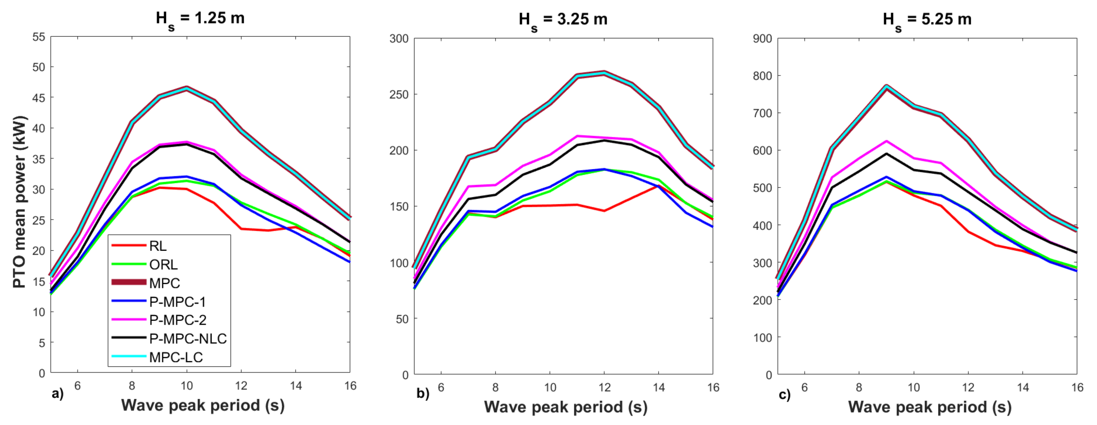
Figure 3 shows the average PTO power for all considered wave profiles and for the control strategies RL, ORL, MPC, P-MPC-1, P-MPC-2, P-MPC-NLC and MPC-LC described above. It can be noted that the traditional MPC strategies (MPC and MPC-LC) allow higher average power absorption due to their reactive nature. This means that the energy is circulating in a bidirectional way between the PTO and the WEC.
On the other hand, the control strategy P-MPC-2 presents better performances than P-MPC-1 in terms of extracted power. The reason is that P-MPC-1 is a simple and faster strategy that keeps the same PTO damping over the entire prediction horizon, while P-MPC-2 has to estimate the PTO force for each time instant over the prediction horizon being more complex and slower.
Taking into account the differences in processing time and the power extracted between both proposed control strategies P-MPC-1 and P-MPC-2, it is convenient to divide the analysis in two groups. The first group is composed by faster control strategies with lower extracted power (P-MPC-1, RL and ORL), and the second one is composed by slower control strategies with higher extracted power (P-MPC-2 and P-MPC-NLC). A third group formed by the reactive control strategies with the greatest extracted power (MPC and MPC-LC) serves as reference for the first and second groups. The MPC strategy without constraints is a convex quadratic programming problem whose solution is fast in terms of processing time. For this reason, the first group is compared to the MPC strategy. Besides, the MPC-LC strategy considers the computational effort when linear restrictions are added. These linear constraints are relaxed, never achieved and added to estimate the processing time in the quadratic programming problem with linear constraints (non-convex programming problem). For this reason, the second group, formed by control strategies, for which passivity is defined in their constraints, is compared to the MPC-LC strategy.
Based on Figure 3, it can be concluded that the proposal P-MPC-1 extracts 5% more average power than the RL strategy and practically the same average power as the ORL reference strategy. On the other hand, the proposal P-MPC-2 allows obtaining 4% more power than the strategy P-MPC-NLC.
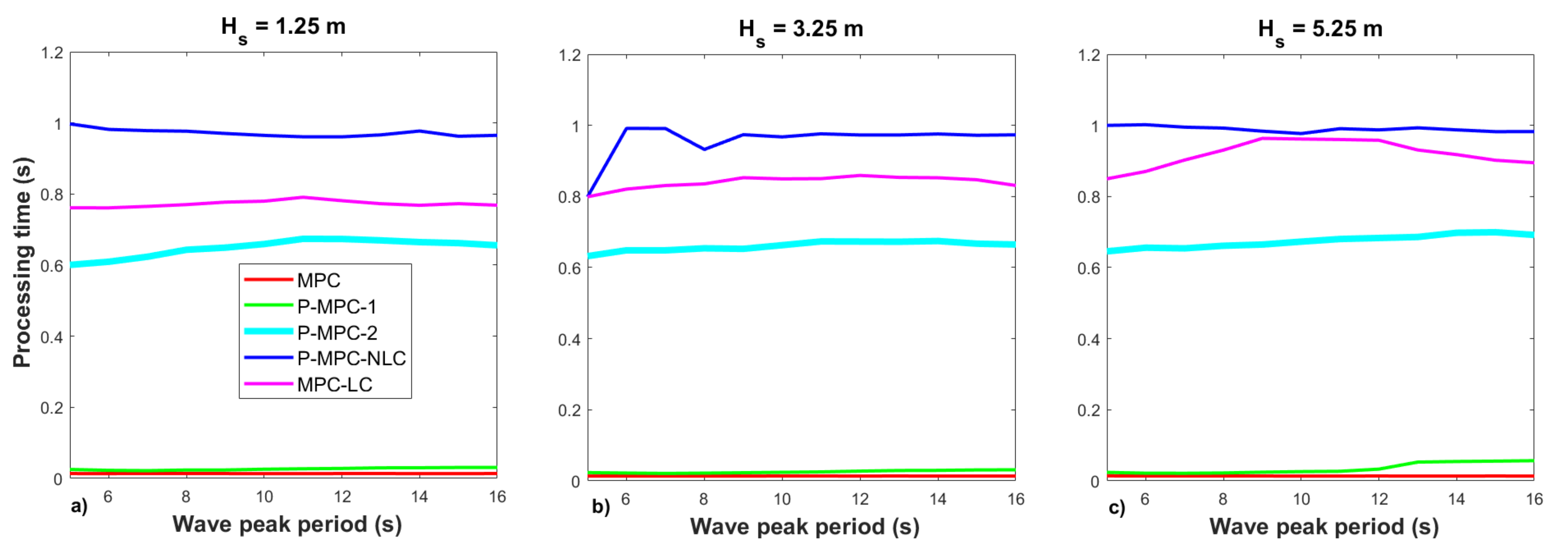
Concerning the average processing time to solve the associated optimization problem, Figure 4 shows that the most time-consuming control strategy is P-MPC-NLC (0.973 s), followed in descending order by MPC-LC (0.844 s), P-MPC-2 (0.661 s), P-MPC-1 (0.029 s) and MPC (0.013 s). It can be highlighted that the processing time of P-MPC-1 is low and in the same order as MPC. On the other hand, the processing time of the control strategy P-MPC-2 is 32% lower than P-MPC-NLC and 22% lower than MPC-LC. According to the results reported in Figure 3 and Figure 4, both proposals are competitive in terms of absorbed power and processing time.
Figure 5 shows that the maximum speed takes high values for MPC and P-MPC-NLC, low values for the control RL and ORL and intermediate values for both proposals P-MPC-1 and P-MPC-2.
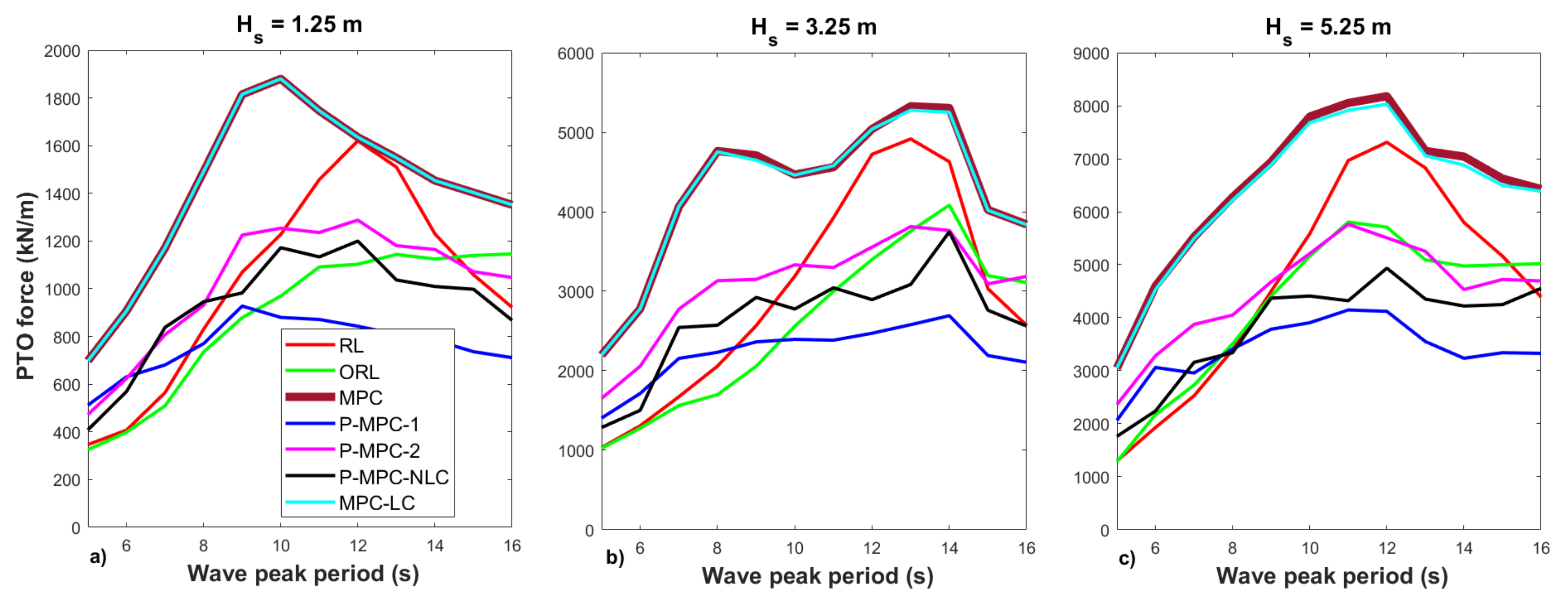
Figure 6 presents the maximum PTO force values for all control strategies and wave profiles. This figure shows that the maximum PTO force takes low values when applying P-MPC-1 and intermediate values similar to the P-MPC-NLC case when applying P-MPC-2.
Summarizing, the control strategy P-MPC-2 extracts more power than P-MPC-NLC consuming less processing time, with intermediate values (between Groups 1 and 3) of the maximum speed and PTO force. On the other hand, the control strategy P-MPC-1 extracts similar power as the reference control strategy ORL, requiring processing time in the same order as MPC.

6.2. Relevant Time Signals

This section presents the relevant waveforms (position, speed, PTO force and PTO power) for the control strategies RL, ORL and both proposals P-MPC-1 and P-MPC-2 in irregular waves with peak period Tp = 12 s and significance wave height 3.25 m. To highlight the difference between the waveforms obtained, they are shown in a 70 s time window from the time instant 30 s to the time instant 100 s.
In Figure 7, higher position and speed values in the control strategies P-MPC-1 and P-MPC-2 compared to RL and ORL can be noted. On the other hand, in Figure 8, lower PTO force and higher PTO power can be observed in both proposals. The noise in the PTO force and power waveforms in proposal P-MPC-2 is due to the values of the PTO damping time series obtained during successive optimization results.
Figure 9 presents the values of the PTO damping as a function of time. It can be noted that the values in both P-MPC-1 and P-MPC-2 vary over time while the PTO damping in the RL and ORL strategies is constant. In addition, the PTO damping in P-MPC-1 presents less abrupt changes and lower values compared to P-MPC-2. The reason for this is that P-MPC-1 is based on keeping the PTO damping constant over the prediction horizon, while P-MPC-2 estimates a different PTO damping for each time instant over the prediction horizon.

6.3. Sensitivity Analysis

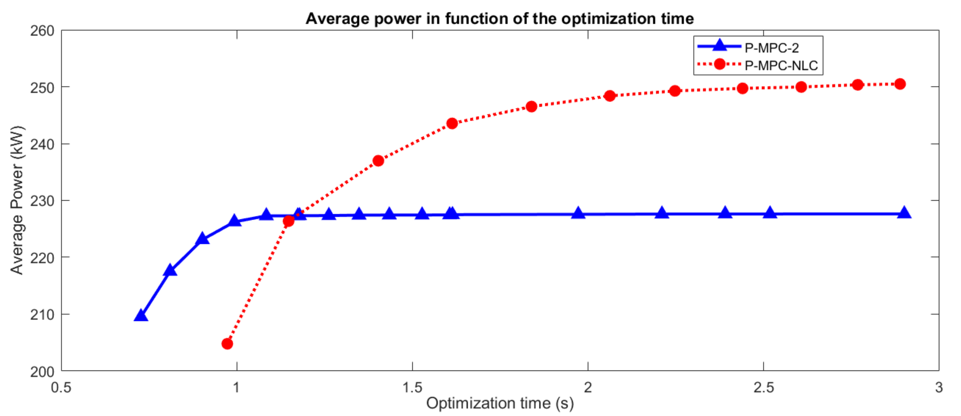
Figure 10 presents the performance of P-MPC-2 and P-MPC-NLP in terms of average power extracted by the PTO as a function of the average time consumed to solve the optimization problem in each time instant.
To vary the processing time, the number of iterations was increased conveniently on both strategies. The wave profile used in this analysis is the sea state with peak period Tp = 12 s and significant wave height Hs = 3.25 m.
In Figure 10, it can be noted that a higher average power is obtained applying P-MPC-2, when the average time spent in the optimization problem is less than 1.15 s., while P-MPC-NLC extracted more power for a higher processing times (greater than 1.15 s).
Since real-time control requires fast response from the processors in order to get an estimation of the control action, the control strategy P-MPC-NLC is not feasible from a technical point of view. On the other hand, as the proposal P-MPC-2 consumed less processing time extracting more average power, it could be suitable for real time implementation.

7. Conclusions

This work proposes two passive MPC control strategies applied to a two-body self-reference point absorber. The first proposal adapts the MPC formulation to a passive loading strategy (P-MPC-1) and the second one adapts the linear constraints in the MPC in order to allow only unidirectional power flow between the wave energy converter and the power take-off (P-MPC-2).
The results show that the first proposal has a processing time in the same order (0.029 s) as the MPC without constraints (0.013 s), extracting 5% more power than the resistive loading (RL) and 0.1% more power than the passive reference control strategy (ORL), achieving intermediate values for PTO speed and low values for PTO force.
On the other hand, the second proposal obtains 4% more average power than the passive MPC strategy with non-linear constraints, consuming 32% less processing time than the passive MPC strategy with non-linear constraints and 22% less processing time than MPC with linear constraints. In addition, this proposal presents intermediate values to the maximum speed and the PTO force.
Due to its low processing time, the first proposal P-MPC-1 could be used to improve the performance of the traditional passive control (RL) including constraint. In this sense, in this article, the first proposal is used to initialize the second proposal. On the other hand, the second proposal could be used to implement a technically feasible passive MPC.
As an MPC strategy, our proposals are very dependent on the model used in their formulation as well as on the prediction of the excitation force. A non-representative model of the WEC would lead to an inefficient MPC strategy.
Author Contributions

Conceptualization, D.M. and E.T.; methodology, D.M.; software, D.M. and T.M.; validation, D.M.; formal analysis, D.M.; investigation, D.M.; resources, E.T., L.C. and T.M.; data curation, D.M.; writing—original draft preparation, D.M.; writing—review and editing, D.M., E.T., L.C. and T.M; visualization, D.M.; supervision, E.T.; project administration, E.T. and L.C.; and funding acquisition, L.C. and E.T. All authors have read and agreed to the published version of the manuscript.

Funding

The IMAGINE project received funding from the European Union’s Horizon 2020 research and innovation programme under grant agreement No. 764066 https://ec.europa.eu/inea/en/horizon-2020/projects/h2020-energy/tidal-wave-hydropower/imagine of the 18 March 2021.

Institutional Review Board Statement

Not applicable.

Informed Consent Statement

Not applicable.

Conflicts of Interest

The authors declare no conflict of interest.

Abbreviations

The following abbreviations are used in this manuscript:
MPCModel Predictive Control
WECWave Energy Converter
QPQuadratic Programming
PTOPower Take-Off
NLPNonlinear Programming
P-MPC-1Passive MPC Proposal 1
P-MPC-2Passive MPC Proposal 2
P-MPC-NLCMPC with Nonlinear Constraint
RLPassive Control
MPC-LCMPC with Linear Constraint
ORLOptimal Passive Control

Appendix A

The WEC of Figure 1 is a two-body self-reference point absorber formed by an external floater ring with a 19.2 m diameter and 4.8 m height that moves with respect to an internal cylindrical spar with a 5.7 m diameter and 36.5 m height attached to the seabed by means of a mooring. The drafts of the floater and spar are 2.8 and 28.8 m, respectively. The heave plate in the submerged extreme of the spar has a diameter of 28.8 m and height of 0.1 m. The floater and the spar have the following values: masses 661 and 799.7 t, hydrostatic coefficients 2640.9 and 260.3 kN/m, viscosity coefficients 104 m and 78 kN·s/m and infinity masses 1101.7 and 7995.3 t. The value of the PTO friction coefficient is 82.4 kN·s/m and the stiffness of the mooring is 10 kN/m. The PTO mass is negligible compared to the mass of the floater and spar.
Both radiation forces F r 1 ( t ) and F r 2 ( t ) were modeled by means of state space equations using third- and second-degree systems:
U ˙ 1 ( t ) = A r 1 U 1 ( t ) + B r 1 z ˙ 1 ( t )
F r 1 ( t ) = C r 1 U 1 ( t )
where
A r 1 = 0.7418 1.0937 0.8431 1.0937 0.0070 0.0466 0.8431 0.0466 0.4280 B r 1 = 3.9929 0.3634 1.6030
C r 1 ( t ) = 1.3642 0.1241 0.5477 10 5
and
U ˙ 2 ( t ) = A r 2 U 2 ( t ) + B r 2 z ˙ 2 ( t )
F r 2 ( t ) = C r 2 U 2 ( t )
where
A r 2 = 0.4260 0.7843 0.7843 0.00004 B r 2 = 1.2278 0.0121
C r 2 = 4.1950 0.0414 10 4
The dynamics of the system was modeled by means of the following state space equations:
X ˙ ( t ) = A X ( t ) + B e 1 F e 1 ( t ) + B e 2 F e 2 ( t ) + B p t o F p t o ( t )
Y ( t ) = C X ( t ) = [ z 1 ( t ) z 2 ( t ) z 1 ˙ ( t ) z 2 ˙ ( t ) ] T
A = 0.7418 1.0937 0.8431 0 3.9929 0 0 0 0 1.0937 0.0070 0.0466 0 0.3634 0 0 0 0 0.8431 0.0466 0.4280 0 1.6030 0 0 0 0 0 0 0 0 1 0 0 0 0 0.0774 0.0070 0.0311 1.4982 0.1057 0 0 0 0.0468 0 0 0 0 0 0.4260 0.7843 0 1.2278 0 0 0 0 0 0.7843 0.00004 0 0.0121 0 0 0 0 0 0 0 0 1 0 0 0 0 0.0094 0.0048 0.00005 0.0307 0.0979
B e 1 = 0 0 0 0 0.5673 0 0 0 0 T 10 6
B e 2 = 0 0 0 0 0 0 0 0 0.1137 T 10 6
B p t o = 0 0 0 0 0.5673 0 0 0 0.1137 T 10 6
C = 0 0 0 1 0 0 0 1 0 0 0 0 0 1 0 0 0 1

Appendix B

In the following, all control strategies used in this paper are explained briefly and summarized in Table A1:
  • The passive control strategy (RL) considers the PTO force proportional to the speed.
    F p t o ( t ) = | Z t h ( ω p ) | ( z 1 ˙ ( t ) z 2 ˙ ( t ) )
    where Z t h ( ω ) = R t h ( ω ) + j X t h ( ω ) is the Thevenin impedance seen from the PTO in the WEC electrical representation and ω p is the wave peak frequency.
  • Optimal passive strategy (ORL) is included as reference control. This control estimates the best PTO damping in terms of power extracted by means of an optimization process on the same wave profile. The ORL requires knowing the entire time series of the wave over the analysis interval. The ORL control strategy is applied only to get a reference to the maximum power extracted by the constant PTO damping passive control.
  • Traditional MPC is included to compare PTO power and processing time results.
  • Traditional MPC with relaxed linear constraints (MPC-LC) is included to estimate how the processing time changes when linear constraints are included in traditional MPC. “Relaxed linear constraints” means that such restrictions are not achieved.
  • Including nonlinear constraints in the traditional MPC (P-MPC-NLC) is the most common way to get passivity in MPC. The drawback is that it is expensive from a computational point of view.
Table A1. Summary of the control strategies applied in the article.
Control StrategyDescriptionProblemMatlab SolverConstraintsAlgorithm
MPCTraditional MPCQPquadprogNointerior-point-convex
P-MPC-1Passive MPCNLPfminsearchNoNelder-Mead simplex
proposal 1
P-MPC-2Passive MPCQPquadprogLinearinterior-point-convex
proposal 2
RLTraditional passive----
ORLReference----
optimal passive
P-MPC-NLCReferenceNLPfminconNLCsequencial quadratic
passive MPC programming
MPC-LCTraditional MPCQPquadprogLinearinterior-point-convex
with relaxed
linear constraints

References

  1. Ocean Energy Systems (OES); International Energy Agency (IEA). An International Vision for Ocean Energt 2017; Technical Report; WavEC-Offshore Renewable: Lisboa, Portugal, 2017. [Google Scholar]
  2. García, A.; Montoya, D.; de la Villa Jaén, A. Output power of linear generators under reactive control in regular waves. In Proceedings of the 9th International Conference on Renewable Energies and Power Quality (ICREPQ), Las Palmas, Spain, 13–15 April 2011. [Google Scholar]
  3. Tedeschi, E.; Carraro, M.; Molinas, M.; Mattavelli, P. Effect of Control Strategies and Power Take-Off Efficiency on the Power Capture From Sea Waves. IEEE Trans. Energy Convers. 2011, 26, 1088–1098. [Google Scholar] [CrossRef]
  4. Hals, J.; Falnes, J.; Moan, T. A comparison of selected strategies for adaptive control of wave energy converters. J. Offshore Mech. Arct. Eng. 2011, 133, 31101-1–31101-12. [Google Scholar] [CrossRef]
  5. Tedeschi, E.; Molinas, M. Impact of control strategies on the rating of electric power take off for Wave Energy conversion. In Proceedings of the IEEE International Symposium on Industrial Electronics, Bari, Italy, 4–7 July 2010; pp. 2406–2411. [Google Scholar]
  6. Faedo, N.; Sebastien, O.; Ringwood, J. Optimal Control, MPC and MPC-Like Algorithms for Wave Energy Systems: An Overview. IFAC J. Syst. Control 2017, 1, 37–56. [Google Scholar] [CrossRef] [Green Version]
  7. Brekken, T. On Model Predictive Control for a Point Absorber Wave Energy Converter. In Proceedings of the IEEE Trondheim PowerTech, Trondheim, Norway, 19–23 June 2011. [Google Scholar]
  8. Hals, J.; Falnes, J.; Moan, T. Constrained optimal control of a heaving buoy wave-energy converter. J. Offshore Mech. Arct. Eng. ASME 2011, 133, 114011–1140115. [Google Scholar] [CrossRef] [Green Version]
  9. Montoya, D.; de la Villa Jaén, A.; García Santana, A. Considering linear generator copper losses on model predictive control for a point absorber wave energy converter. Energy Convers. Manag. 2014, 78, 173–183. [Google Scholar] [CrossRef]
  10. Hansen, A.; Asmussen, M.; Bech, M. Model Predictive Control of a Wave Energy Converter with Discrete Fluid Power Power Take-Off System. Energies 2018, 11, 1–17. [Google Scholar]
  11. O’Sullivan, A.; Lightbody, G. Co-design of a wave energy converter using constrained predictive control. Renew. Energy 2017, 102, 142–156. [Google Scholar] [CrossRef]
  12. Paparella, F.; Bacelli, G.; Paulmeno, A.; Mouring, S.; Ringwood, J. Multibody Modelling of Wave Energy Converters Using Pseudo-Spectral Methods With Application to a Three-Body Hinge-Barge Device. IEEE Trans. Sustain. Energy 2016, 7, 966–974. [Google Scholar] [CrossRef] [Green Version]
  13. Paparella, F.; Bacelli, G.; Paulmeno, A.; Mouring, S.; Ringwood, J. Optimal Control of a Three-Body Hinge-Barge Wave Energy Device Using Pseudospectral Methods. IEEE Trans. Sustain. Energy 2017, 8, 200–207. [Google Scholar] [CrossRef]
  14. Tom, N.; Yeung, R. Nonlinear Model Predictive Control Applied to a Generic Ocean-Wave Energy Extractor. J. Offshore Mech. Arct. Eng. 2014, 136, 4190101–4190112. [Google Scholar] [CrossRef]
  15. Cruz Atcheson Consulting Engineers. WEC Models Database Report. Deliverable 2.1; Technical Report; IMAGINE Project, NTNU: Trondheim, Norway, 2018. [Google Scholar]
  16. Luca, C.; Andrea, M.; Martini, M.; Alessandri, G.; Coiro, D.; De Lucas, F.; Calise, G.; Troise, G.; Vogler, A. Experimental tests on a wave-to-wire pivoted system for wave energy exploitation. In Proceedings of the 6th International Conference on Clean Electrical Power: Renewable Energy Resources Impact, ICCEP 2017, Santa Margherita Ligure, Italy, 27–29 June 2017; pp. 479–487. [Google Scholar]
  17. Luca, C.; Andrea, M.; Borgarelli, N. Analysis and Design of a Reciprocating Linear Generator for a PTO. In Proceedings of the International Symposium on Power Electronics, Electrical Drives, Automation and Motion Analysis SPEEDAM 2014, Ischia, Italy, 18–20 June 2014; pp. 1373–1379. [Google Scholar]
  18. Richter, M.; Magana, M.; Sawodny, O.; Brekken, T. Power optimisation of a point absorber wave energy converter by means of linear model predictive control. IET Renew. Power Gener. 2014, 8, 203–215. [Google Scholar] [CrossRef]
  19. Falnes, J.; Yu, Z. State-Space Modelling of a Vertical Cylinder in Heave. Appl. Ocean. Res. 1996, 17, 265–275. [Google Scholar]
  20. Chen, C.T.S. Linear System Theory and Design, 3rd ed.; Oxford University Press: New York, NY, USA, 1999. [Google Scholar]
  21. Cretel, J.; Lightbody, G.; Thomas, G.; Lewis, A. Maximisation of Energy Capture by a Wave-Energy Point Absorber using Model Predictive Control. In Proceedings of the Preprints of the 18th IFAC World Congress, Milano, Italy, 28 August–2 September 2011; pp. 3714–3721. [Google Scholar]
  22. Camacho, E.; Bordons, C. Model Predictive Control, 2nd ed.; Springer: Berlin/Heidelberg, Germany, 2007. [Google Scholar]
  23. Rossiter, J. Model Based Predictive Control. A Practical Approach; CRC Press: Boca Raton, FL, USA, 2004. [Google Scholar]
  24. Neary, V.; Previsic, M.; Jepsen, R.; Lawson, M.; Yu, Y.H.; Copping, A.; Fontaine, A.; Hallet, K.; Murray, D. Methodology for Design and Economic Analysis of Marine Energy Conversion (MEC) Technologies; Technical Report SAND2014-9040; Sandia National Laboratories: Albuquerque, NM, USA, 2014. [Google Scholar]
  25. Babarit, A.; Hals, J.; Muliawan, M.; Kurniawan, A.; Moan, T.; Krokstad, J. Numerical benchmarking study of a selection of wave energy converters. Renew. Energy 2012, 41, 44–63. [Google Scholar] [CrossRef]
Figure 1. Two-body self-reference point absorber wave energy converter.
Energies 14 01731 g001
Figure 2. Electro-mechanical ball-screw PTO concept.
Energies 14 01731 g002
Figure 3. Average PTO power in irregular wave varying the peak period T p from 4 to 16 s for significance high: (a) H s = 1.25 m; (b) H s = 3.25 m; and (c) H s = 5.25 m.
Energies 14 01731 g003
Figure 4. Average processing time in irregular wave varying the peak period T p from 4 to 16 s for significance high: (a) H s = 1.25 m; (b) H s = 3.25 m; and (c) H s = 5.25 m.
Energies 14 01731 g004
Figure 5. Maximum speed in irregular wave varying the peak period T p from 4 to 16 s for significance high: (a) H s = 1.25 m; (b) H s = 3.25 m; and (c) H s = 5.25 m.
Energies 14 01731 g005
Figure 6. Maximum PTO force in irregular wave varying the peak period T p from 4 to 16 s for significance high: (a) H s =1.25 m; (b) H s = 3.25 m; and (c) H s = 5.25 m.
Energies 14 01731 g006
Figure 7. Position (a); and speed (b) of the PTO for the sea state Tp = 12 s and Hs = 3.25 m.
Energies 14 01731 g007
Figure 8. Force (a); and power (b) of the PTO for the sea state Tp = 12 s and Hs = 3.25 m.
Energies 14 01731 g008
Figure 9. PTO damping for the sea state Tp = 12 s and Hs = 3.25 m.
Energies 14 01731 g009
Figure 10. PTO damping for the sea state Tp = 12 s and Hs = 3.25 m.
Energies 14 01731 g010
Publisher’s Note: MDPI stays neutral with regard to jurisdictional claims in published maps and institutional affiliations.