1. Introduction
As the global demand for the more efficient drilling of oil wells is increasing, long horizontal wells with extended reaches are becoming more common; thus, this comes with intrinsic challenges of the more complex structures, such as a weakened hole-cleaning efficiency, as the drilling cutting particles tend to precipitate inside the wellbore by gravity through a long area [
1]. These drilling cuttings are debris composed mainly by sandstones and shales with specific gravities between 2.2 and 2.7, with an average of 2.6, and sizes varying widely between a couple of microns to tens of millimeters [
2,
3,
4], the most common range being between 0.5 mm to 2.5 mm. Examples of the typical particle size distributions from different top-hole sections have been published [
5].
A large area for the sedimentation of drilled cuttings and their accumulation produces long cutting beds in highly inclined or horizontal annulus. During drilling, such cutting beds produce a high risk for pipe sticking, hole pack-off, high drag and torque, a low rate of penetration (ROP) and high annular circulating pressure. Hence, the risk for running into lost circulation increases. Similarly, the probability of being able to run casing strings or completion strings without excessive problems increases.
Therefore, researchers have studied different factors to describe and optimize the hole-cleaning efficiency. These hole-cleaning factors can be divided into three categories [
6]: operational factors, drilling fluid parameters and drilled cutting characteristics. The understanding of the interactions of these factors combined still needs to be improved.
Previous studies have shown that there are two main transport phenomena present during the flow in hole cleaning, lifting and dragging. Drag forces are anticipated to be the most important cuttings bed eroding force in highly deviated and horizontal wells [
7]; thus, they must be analyzed to determine how cuttings bed erosion can be improved in wells with high inclinations and horizontal wells.
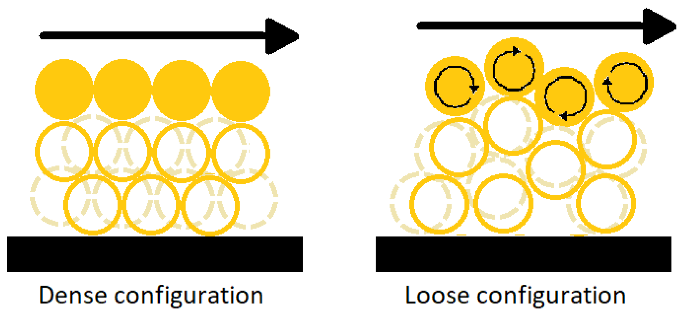
The particle dragging movement within cutting beds is governed by two types of configurations:, loose and dense configurations [
8]. In the dense configuration, particle cohesion is higher; therefore, there is a more dominant movement of particles as a cluster, instead of single elements; thus, in the loose configuration, particle cohesion is lower, allowing particles to move freely as single elements, as shown in
Figure 1.
Additionally, the increased shear forces on the cuttings bed resulting from the rotation of the drill pipe in the eccentric annulus is a major contributor to hole cleaning. When pipe rotation is applied, the cuttings bed can be broken due to a combination of hydrodynamic forces, such as shear stresses caused by rotational flow with or without Taylor vortices and by direct friction forces. In both cases, the drilled cuttings will be effectively lifted from the bed and moved to an area with a strong axial flow where the fluid flow will transport them out. The efficiency of the drill pipe rotation on cuttings transport is similarly dependent on the cuttings bed properties.
Granular particles with interstitial fluids behave both as a solid and liquid. The behavior depends on the solid fraction (φ), the internal friction coefficient (
µ*), by cohesive forces between particles, e.g., due to capillarity [
9], and by the rheological properties of the interstitial fluid. As a result, the net shear strength of the bed might be different for different interstitial fluids, such as water-based or oil-based drilling fluids [
10].
Sayindla et al. [
11] verified the field perception that oil-based drilling fluids (OBM) presents better hole-cleaning capabilities than KCl/polymer water-based drilling fluids (WBM) do, even if their viscous properties are similar. Hence, these difference in cleaning capabilities cannot be explained solely by evaluating the flowing parameters of the drilling fluid [
12].
In the current work, the fluid-saturated particle bed was observed as a flowing material, and rheological characterization was performed to obtain the internal friction coefficient. The internal friction coefficient behavior between wet cutting particles and these particles with the surroundings was measured. In different sets of experiments, the particles were wetted with water-based and oil-based drilling fluids used in actual drilling operations.
2. Methods and Materials
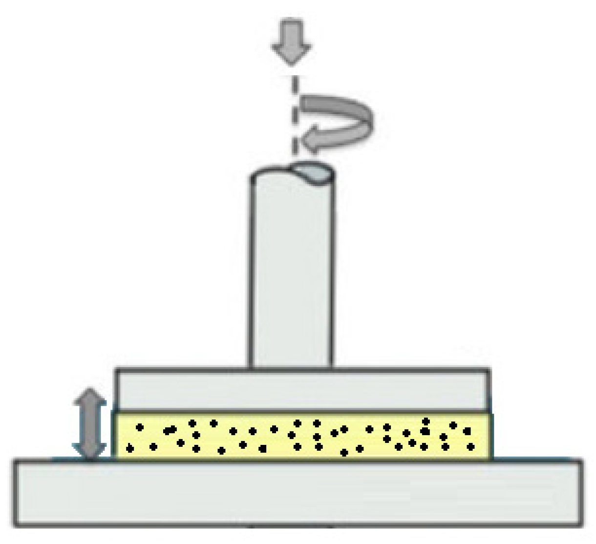
For this study, an Anton Paar Physica MCR-301 rheometer with parallel-plate geometry was used for the oscillatory and rotational testing, as shown in
Figure 2; the plate diameter was 50 mm (PP50), maintaining a constant temperature at 25 °C for all the tests. Sand grains with 1.3-mm average sizes were used to simulate the drilling cuttings. The WBM and OBM samples were provided by Schlumberger MI-Swaco Fluids, Norway. These two drilling fluids had similar rheological properties and similar operational behaviors on the field.
The water-based fluid was composed of water, KCl, NaOH, starch, PAC, Xanthan gum, glycol and barite. This drilling fluid had a specific gravity of 1.49. The oil-based drilling fluid was composed of an inverse emulsion of water in oil, emulsifiers, CaCl, organophilic clay, lime, fluid loss agents and barite to obtain a specific gravity of 1.58 s.g.
The procedure to build the cuttings bed was done following the one described by Vrålstad et al. [
11]. Several centrifuge tubes were filled, each in the following way: cuttings particles represented 25% of the total weight, and the other 75% of the weight was completed with drilling fluid; then, the centrifuge tubes were hand-shaken for two minutes for homogenization. In order to simulate particle sedimentation over time in an accelerated manner, the samples were centrifuged at 3000 RPM for 20 min. The resulting fluid was disposed, and samples from the bottom of the centrifuge tubes were collected and placed into the plate, forming a bed with height of 3.6 mm to be sure that there was at least 1 row of cutting particles overlapping each other.
Amplitude sweeps at a constant frequency of 10 Hz and strain amplitude varying from 0.001% to 100% of the angular displacement at the perimeter of the plate were performed to observe the viscoelastic behavior of the cutting particles, with each interstitial fluid as an entire bed.
Continuous rotational test with a shear rate from 0.001–1 s
−1 taking 120 points logarithmically were performed under two different conditions: one kept a constant gap between the rheometer plates of approximately 3.6 mm ± 0.2 with variable normal force, and another one kept a constant normal force around 1 N or 3 N and modified the gap between the plates, thus obtaining the data under the two different conditions to calculate the internal friction coefficient,
µ* [
13], according to Equation (1):
where
FN is the normal force,
σ is the shear stress,
P is the normal stress and
A is the area of the plate geometry, assuming full contact with the particles. The statistical software JMP from SAS was used to illustrate and analyze statistically the results of the internal friction coefficient from the rotational tests. Friction coefficient values ranged between 0 and 1, although, in some cases, it could be higher than 1, meaning that the frictional force was higher than the normal force.
3. Results
3.1. Amplitude Sweeps
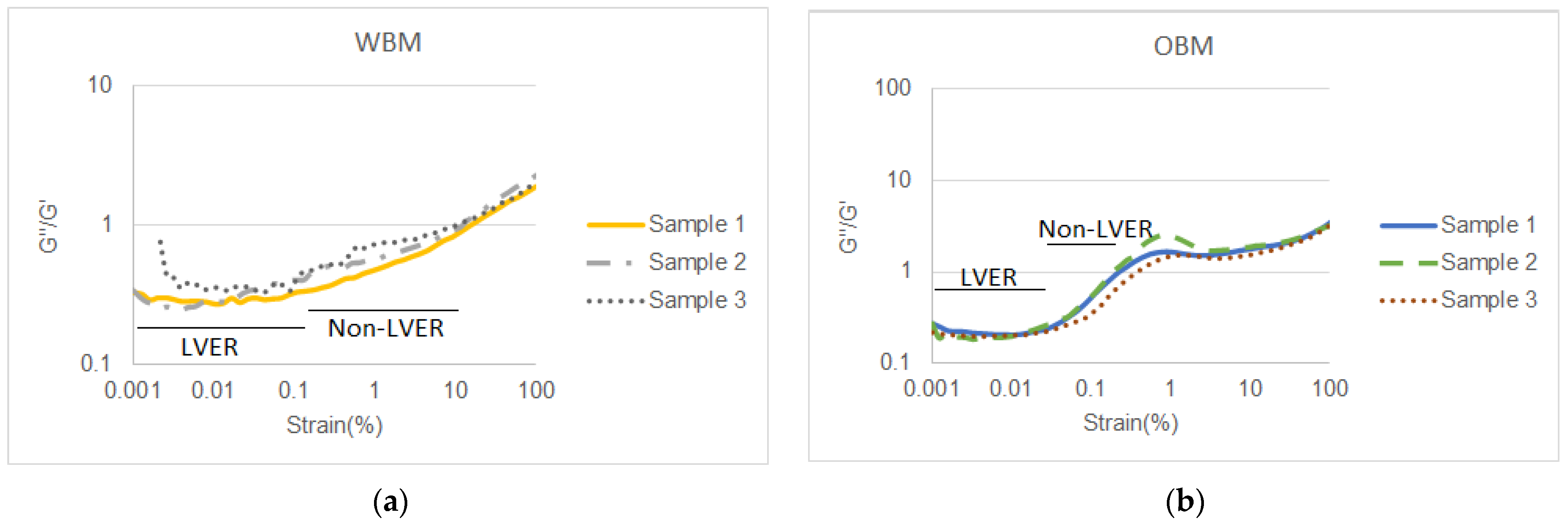
The storage modulus (G′) divided by the loss modulus (G″) as a function of the strain in the cuttings bed is shown in
Figure 3, with (a) water-based drilling fluid and (b) oil-based drilling fluid as the interstitial fluids. This G″/G′ curve characterizes the material elastic, viscous or viscoelastic behaviors. When G″/G′ < 1, the elastic behavior dominates the viscous behavior; thus, the cuttings bed shows a solid-like character maintaining its structure together, suffering only small elastic deformations. In the case where G″/G′ > 1, the viscous behavior dominates, and the sample acts liquid-like, which indicates that the cuttings bed as a body has suffered a complete breakage of the internal structure and, thus, irreversible deformation. The crossover point (G″/G′ = 1) is called the flow point.
The limit of the linear viscoelastic region (LVER) is considered to be when the curve reaches 10% deviation from the plateau [
14], which indicates the minimum strain to initiate breakage of the inner structure, suffering plastic deformations, and the nonlinear viscoelastic region goes from the point where the LVER ends until the crossover point, G″/G′ = 1. On a fluid material, usually, the LVER is longer than the nonlinear region.
In the measurement data shown in
Figure 3a, the cuttings bed wetted with water-based drilling fluid presents a longer linear viscoelastic region (LVER) than the oil-based; it is also possible to observe in
Figure 3b that the cuttings bed wetted with oil-based drilling fluid presents a much shorter nonlinear viscoelastic region.
3.2. Continuous Rotational Tests
The internal friction coefficient as a function of the continuous rotational results is plotted in a XY chart to visualize the behavior through the shear rate spectrum, and it is also analyzed under violin plots to visualize the density distribution of the internal friction coefficient.
3.2.1. Measurements under Constant Parallel-Plate Gap
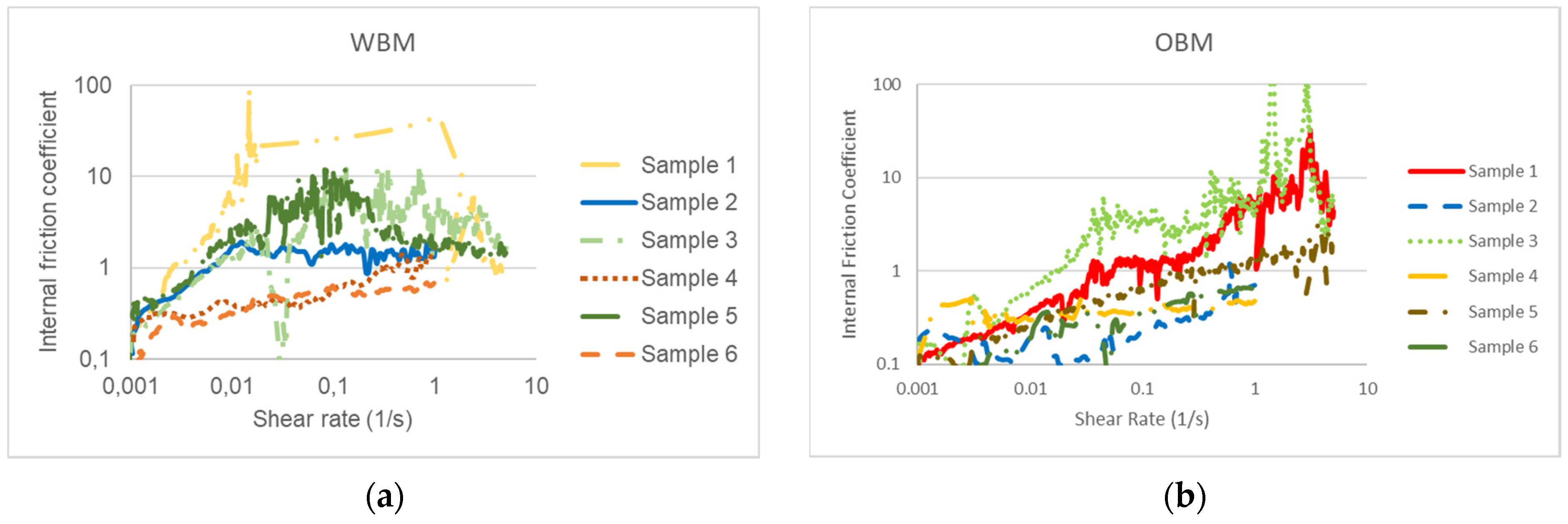
In
Figure 4, it is shown the results for the internal friction coefficient versus shear rate of the cuttings bed particles wetted with each type of fluid: (a) water-based and (b) oil-based, maintained a constant gap between the plates and variable normal force. A stable increasing trend of the internal friction coefficient along the shear rate spectrum from the cuttings bed wetted with OBM is shown, while a random behavior in the internal friction coefficient values for the cuttings bed wetted with WBM is observed.
In both cases, it is possible to observe that the internal friction coefficient has values higher than 1. This does not mean that the frictional forces are higher than the normal force. It means that the particles at the cuttings bed have rearranged outside the parallel plates in a way that they do not have full contact with the upper plate in the rheometer, and as the gap is held constant, it does not correct that lack of contact with the upper plate; meanwhile, the rheometer assumes full contact for the calculations.
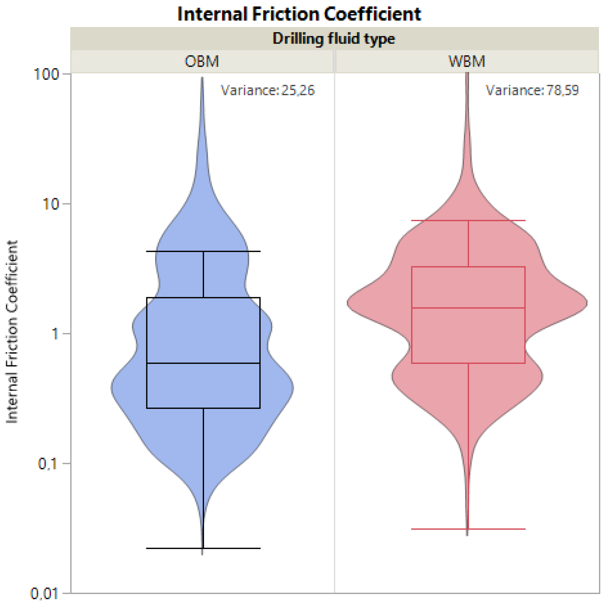
Violin plots are used to illustrate the density distribution of the internal friction coefficient under constant normal force. The vertical axis represents the internal friction coefficient regardless of the shear rate, while the horizontal axis is the estimated data distribution. The boxplots indicate the variability of the data, including the minimum and maximum values, as well as the Q1 in the lower part of the box, which represents the central point between the median and the lowest value, the median is the line in the middle of the box, and Q3 is the upper line of the box, which represents the central point between the median and the highest value for the cuttings bed with both type of drilling fluids as the interstitial fluid, the water-based and the oil-based.
In
Figure 5, is observed that the internal friction coefficient of the cutting particles with WBM is distributed mainly below 1, with a median of 0.59 and a variance of 25.26, while the particles wetted with OBM present an internal friction coefficient distributed mainly above 1, with a median of 1.59 and a variance of 78.59.
The fact that there are many values above 1 can be explained due to the rearrangement of the cuttings bed shape, as it moved downwards as the normal force provoked deformation in the bed, leaving less particles to make contact between the plates, making the data highly inaccurate.
3.2.2. Measurements under Constant Normal Force
To avoid the difficulties in interpreting the results with the friction forces larger than the normal forces, the same types of tests were performed but, in this case, by maintaining a constant normal force. The gap between the plates was automatically adjusted to obtain the full contact area between the plates and the cuttings bed.
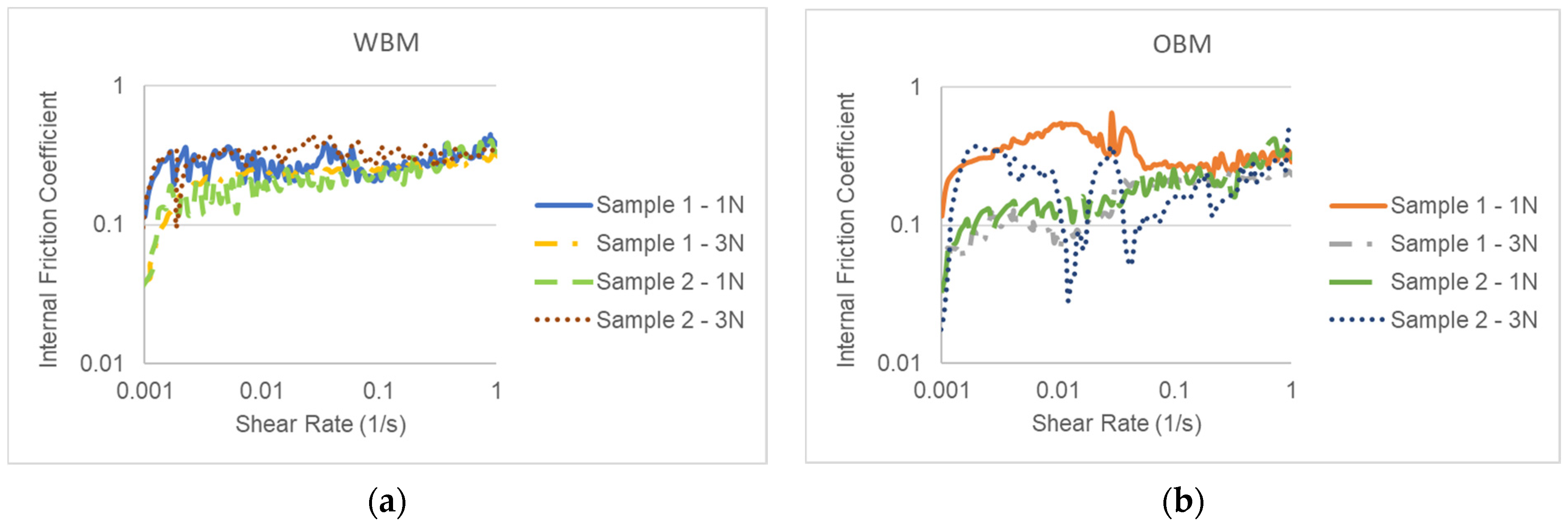
The results for the internal friction coefficient are shown in
Figure 6. This friction coefficient is shown in Equation (1). The figure shows the friction coefficient versus the shear rate of the cuttings bed particles in each type of fluid—(a) water-based and (b) oil-based drilling fluids. Here, the rheometer was set up for maintaining a constant normal force and thus allowed for a variable gap between the rheometer plates. A stable trend of the internal friction coefficient over a large part of the shear rate spectrum from the WBM samples is shown, while a random behavior in the internal friction coefficient values for the OBM is observed.
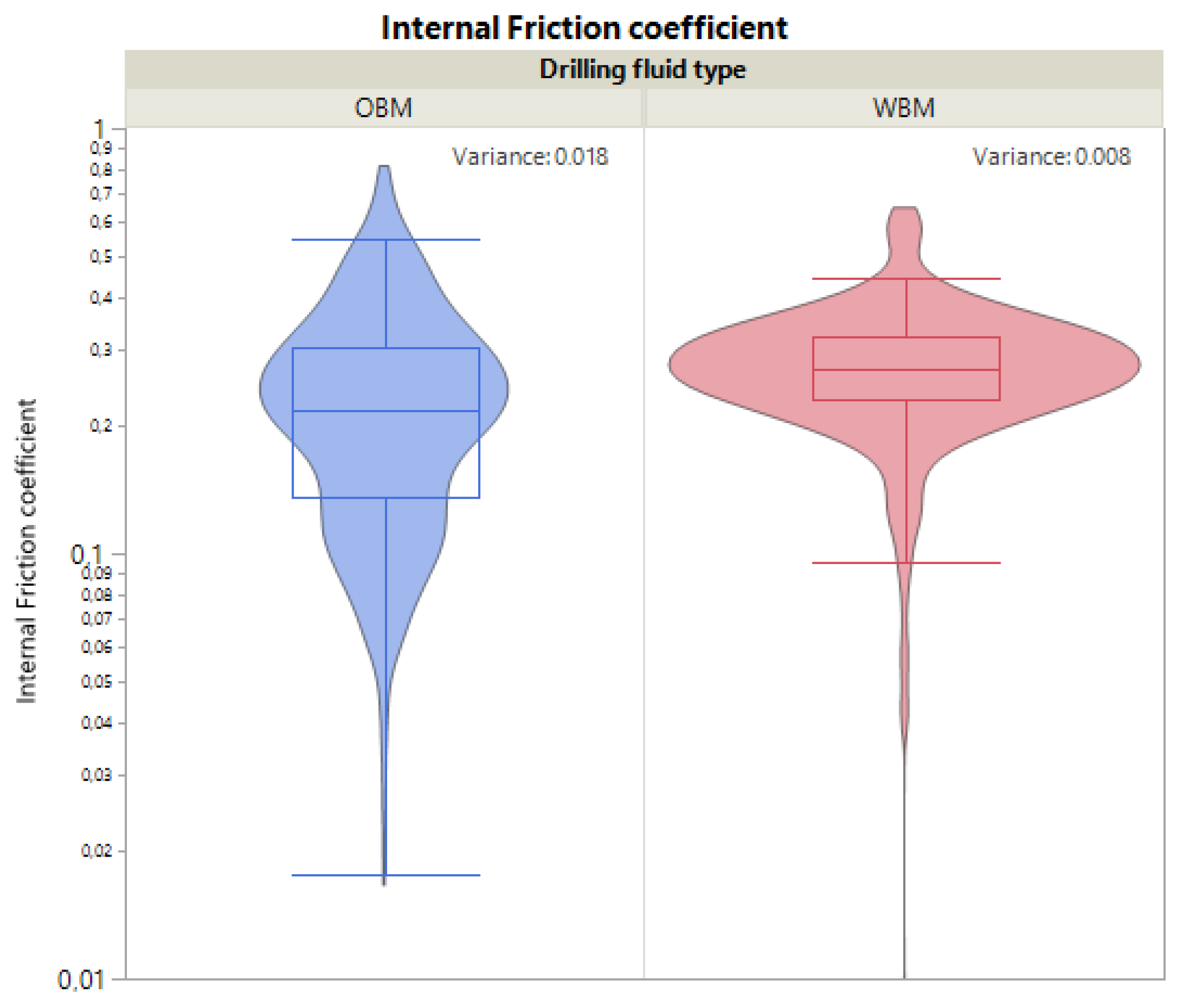
The internal friction coefficient of the cutting particles wetted with the WBM is distributed more uniformly around a median of 0.27, with a variance of 0.008 and a mean of 0.24, as shown in
Figure 7. The particles wetted with OBM presented a wider internal friction coefficient spectrum and a median of 0.22, a higher variance of 0.018 and higher mean of 0.28.
4. Discussion
The oscillatory curves in
Figure 2 show that the cuttings bed wetted with WBM takes longer to reach the point of full deformation, G″/G′ = 1, suggesting that this cuttings bed has a dense configuration and, thus, moves the particles as a cluster, which requires more energy. In the other hand, the cuttings bed wetted with OBM has a loose configuration, where single particles move freely within the bed, requiring less energy to initialize and reach full deformation.
The continuous rotational test, maintaining a constant gap between the parallel plates, undergoes deformation of the cuttings bed shape, stretching to the sides and losing height and, therefore, losing contact area; as this occurs, it is not possible to be aware of the real contact area between the cuttings bed and the upper plate where the calculations are made when assuming the area of the plate.
As the internal friction coefficient depends on the shear stress (σ) and the normal stress (P), and these two depend on the area, inaccuracy of the area will result in unrealistic internal friction coefficient values, as shown in
Figure 3 and
Figure 4.
Shear stress depends on the torque (
T), where a torque on a circular disc of the radius (
r) equal to
R is defined as
Assuming the shear stress (
σ) to be uniform, we have
The normal force (
FN), assuming the uniform normal stress
P, is
Thus, the internal friction coefficient is defined in terms of the torque and normal force as follows:
However, if the actual contact area
Aa is different than the nominal contact area
A, we have
Thus, when having a lower actual contact area (Aa), the actual value of the internal friction coefficient (µa) calculated from the measured values of the normal force and torque is larger than the real internal friction coefficient (µ). Therefore, it is of utmost importance to perform the measurements of normal force and torque with an actual contact area as close as possible to the nominal area of the plates.
The continuous rotational test, maintaining a constant normal force and allowing the parallel-plate gap to automatically adjust, corrects the accuracy of the results by adjusting the gap to the cuttings bed deformation to maintain the actual contact area as close as possible to the nominal area of the plates, thus obtaining all the internal friction coefficient values within the range between 0 and 1.
The cuttings bed wetted with WBM under constant normal force presented a higher internal friction coefficient mean value, lower variation and more narrow data distribution, which suggests that the cohesion between the cutting particles is higher when wetted with water-based drilling fluid, thus forming a cluster where the energy requirement to move it is stable.
Contrary to the behavior of the cuttings bed wetted by the OBM, where the internal friction coefficient has a higher variation, a lower cohesion between the particles suggests that the cuttings bed with the OBM as its interstitial fluid has a loose configuration, as the energy requirements vary according to the number of particles moving within the bed.
5. Conclusions
Wet-granular rheology can be used to calculate the internal friction coefficient of the cuttings bed. From this coefficient, it is possible to indicate the particle cohesion properties. The knowledge of these properties are needed to optimize the drilling fluid with respect to the wellbore cleaning efficiency.
A cuttings bed wetted with KCl/polymer water-based drilling fluid can be defined as a dense configuration; therefore, the cutting particles tend to move in clusters, while the cuttings bed wetted with oil-based drilling fluid shows a loose configuration, where the movements of single particles are likely to be the most common.
The current results showed the steps to develop a method to see the differences between drilling fluids and improve the modeling and planning. Therefore, the differences presented in the internal friction coefficients between the OBM and WBM fluids should not be generalized to every drilling fluid, as they were analyzed by only one type of KCl/polymer WBM and one type of OBM.


