1. Introduction
In recent years, the penetration of renewable energy resources in power systems is increasing rapidly, especially for Wind Energy Conversion Systems (WECS) and Photovoltaic Systems (PV) [
1,
2]. The WECS energy and PV energy are naturally vary volatile and weather dependent. In such cases, the simultaneous use of combined wind and solar sources of energy instead of using just one source of energy (wind energy or solar energy) provides a more profitable and reliable system. Moreover, the joint operation of both such systems can supply a higher number of loads if required.
A Hybrid Renewable Energy System (HRES) is considered as a complex integrated system, involving two or more types of renewable energy sources. Hybrid Renewable Energy Systems are now becoming popular for power generation applications due to advances in renewable energy technologies. These systems are attractive because the individual sources could complement one another to provide more reliable power to the customer than a single-source system. In order to ensure the better conditions for continuity of power delivery to the local loads, it is essential to make WECS and PV systems compatible with additional energy storage systems [
3,
4]. In this case, the battery bank, flywheel, super capacitor, or fuel cell may be used as the energy storage devices [
5].
The following general definition has been formulated and considered in this paper: Hybrid Renewable Energy System (HRES) is the system, which consists of two or more energy sources, with at least one of them renewable and integrated with power control equipment and an optional storage system. The HRES systems can be designed for two modes: One is grid-assisted mode and the other is stand-alone mode. In the grid-assisted mode, when the hybrid system is unable to feed the required power to the loads, it takes the missing part of the power from the AC grid. In the stand-alone mode, which is usually used to supply customers in remote areas, the required power is delivered only by hybrid wind-solar-storage energy system. The stand-alone mode can be considered as the special operation case of grid-assisted mode, when the grid energy is temporarily not available. The HRES systems are usually optimized for Maximum Power Point Tracking (MPPT) to extract the maximum power from the wind and the solar energy sources. This problem can be solved by using appropriate power electronics converters and suitable control strategies.
So far, HRES systems have been the subject of scientific research presented in a certain number of the published papers. However, the analysis presented in the most of the articles was concerned with the operating states of HRES systems of simple topology. The studies were performed for the limited number of operation modes and with consideration for not complex control algorithms. The classification and the architectures of HRES systems were presented in [
6,
7,
8]. The optimization methods of sizing of HRES components were presented in [
1,
7,
8]. In [
9], the wind/PV/super capacitors/battery systems were studied. In [
4,
7], the authors studied the HRES systems in stand-alone mode with DC loads, and in [
3,
10], the HRES systems with AC loads. Many articles deal with the work of the HRES system only in the stand-alone mode [
4,
5,
10] and do not include the issues of energy management strategies [
2,
3,
5,
7,
10,
11,
12,
13,
14]. In most articles, the studies of the system with simple topology of machine side converter connected to Permanent Magnet Synchronous Generator (PMSG) were performed [
3,
7,
9,
10,
11,
12,
13]. The machine side converter is analyzed in the form of a three-phase diode rectifier in cascade operation with DC/DC boost controller. In the systems with grid mode operation for the grid side converter, the simple hysteresis control of converter was applied [
3,
11]. The hysteresis control of the grid converter is not precise and can have an unfavorable impact on the supply network. Some authors were studied HRES operation with complex energy storage systems with fuel cells, supercapacitors, hydrogen technologies, and bioreactors [
5,
9,
10,
15,
16]. Although, as presented above, there is a certain amount of literature regarding HRES systems and their applications, the issues of HRES systems can be still considered as an unmatured technology, which requires further research.
The objective of the article is the review and the study of the performance of the complex HRES system and its control. The analyzed HRES system was modelled mathematically and implemented in a simulation program, developed in Matlab/Simulink environment. The simulation studies have been performed for different conditions of operation of individual elements of the complex hybrid system. The performed studies of the combined operation of the hybrid system are far more complex than known studies of operating them separately. In the hybrid system, with wind and solar energy, both energy sources should be controlled simultaneously, depending upon the operating conditions and energy demands of the system. The energy management strategies for optimal flows of electrical energy between individual parts of considered HRES have been developed. The energy management strategies were developed for grid mode of operation and standalone mode of operation. In the management strategies the different conditions of produced power distribution, the load demands, the battery state of the charge, and the battery power limitation during charging and discharging process were included. The considered control methods and energy management strategies were tested during different wind speed variations, different sun irradiations, different local load demands, and different states of charge of battery. The performed simulation studies should have suitable practical meaning in terms of operation, design selection, and energy management of Hybrid Renewable Energy Systems.
In opinion of the authors, the key contributions of this paper include: The combined analysis and simulation studies of complex HRES system with wind source of energy, photovoltaic source of energy and battery storage system; taking into account the modern multi-converter system of power electronics converters for conversion and storage of electrical energy; application of modern and advanced vector control methods for precise control of machine converter and grid converter; application of MPPT algorithms for high-efficiency conversion of renewable energy obtained from wind turbine and PV array and the development of energy management strategies applied in HRES for grid-mode and stand-alone mode of operation with limitation of battery power and control of its state of charge.
The paper is organized as follows. In
Section 2, the classification of architectures of HRES systems is presented. In
Section 3, the mathematical models of the main components of the HRES system are described and discussed. In
Section 4, the control algorithms for individual energy conversion systems are considered. In
Section 5 the issues of energy management strategies applied in HRES are presented. The performed simulation results have been discussed in
Section 6, and
Section 7 includes the conclusions from the performed studies.
2. The Architectures of Converter Hybrid Renewable Energy Systems
In the literature, the schemes of converter hybrid renewable energy systems are classified into following general types of architecture: DC-coupled HRES, AC-coupled HRES, and HRES of mixed structure [
12,
13,
14].
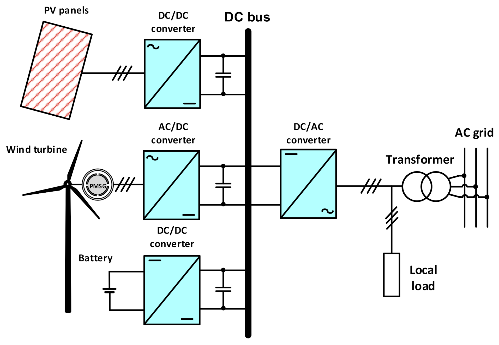
The form of DC-coupled architecture is presented in
Figure 1. This architecture implies the connection of all converter systems through a common DC bus [
7,
14,
17]. The considered system consists of: Wind Energy Conversion System (WECS), Photovoltaic (PV) panels, and Battery Energy Storage (BES). The DC sides of individual converter systems of PV converter, wind turbine WT and PMSG converter, battery bank BES converter and grid converter are connected to the one common DC bus. A single common DC/AC grid converter is used in this system. HRES is a combination of many components. The WECS includes the Wind Turbine (WT) and the Permanent Magnet Synchronous Generator (PMSG). The stator phase winding of PMSG is connected to the AC/DC converter, which is specified as the Machine Side Converter (MSC). In order to obtain the maximum power conversion from the wind, the Maximum Power Point Algorithm (MPPT) has been applied in the control of PMSG and MSC. The PV panel system is connected to the DC/DC boost converter. In the control of this converter system, the MPPT algorithm is also applied in order to achieve the maximum power from PV source of energy. The battery bank is connected to the DC bus through bidirectional DC/DC converter. In the control of this converter the proper charging and discharging strategies of the battery bank are implemented.
In
Figure 2, the AC-coupled architecture of a grid-connected hybrid renewable energy system with a common AC bus has been presented [
14]. In this architecture, several individual DC/AC converters are applied instead of one common DC/AC converter. It means that each individual energy system uses a separated converter system, where all AC sides of these converters are connected to the common AC bus. In the control of wind and PV sources of energy, the systems of MPPT are also applied.
In addition to both architectures presented above, the mixed HRES structures are also applied, in which the advantages of DC-coupled and AC-coupled architecture are jointly used.
The detailed analysis of the individual subsystems should be performed in order to define the principles of selection and control algorithms of the entire system. In this paper, the detailed investigation of the DC-coupled architecture has been chosen for particular studies. This is due to the fact that this architecture is the most widely used because of its flexibility, extensibility, and free choice of the types of connected energy sources.
The extended form of the considered DC-coupled architecture has been presented in
Figure 3. This hybrid renewable system is composed of: Wind turbine system with PMSG and Machine Side Converter MSC, PV arrays with a DC/DC boost converter system, and a battery energy system BES with bidirectional DC/DC converter. All DC sides of the individual converters are connected to the common DC bus of Grid Side Converter GSC.
4. Control of Converter Systems of HRES
4.1. Control of DC/DC Converter for PV Array
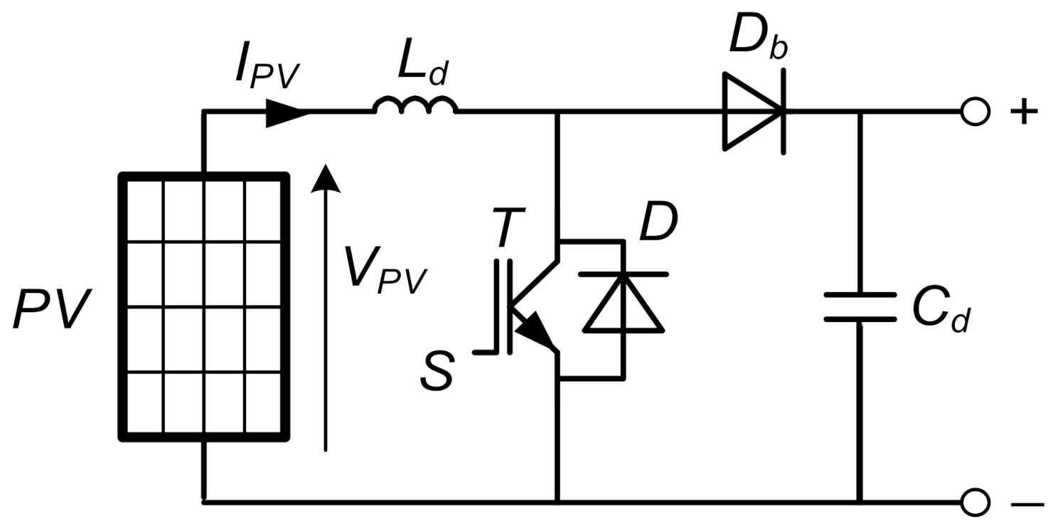
For conversion of the electrical energy obtained from the PV array, the converter of topology of the DC/DC Boost Converter is applied. The scheme of this type of converter is presented in
Figure 8. The DC/DC converter is comprised of controlled switch
S, diode
Db, boost inductor
Ld, and filter capacitor
Cd.
In order to improve the operation and the efficiency of the PV array, the MPPT algorithm has been used for the operation control of the PV converter. In this paper, the Perturb and Observe (P&O) algorithm has been implemented [
30,
31,
32].
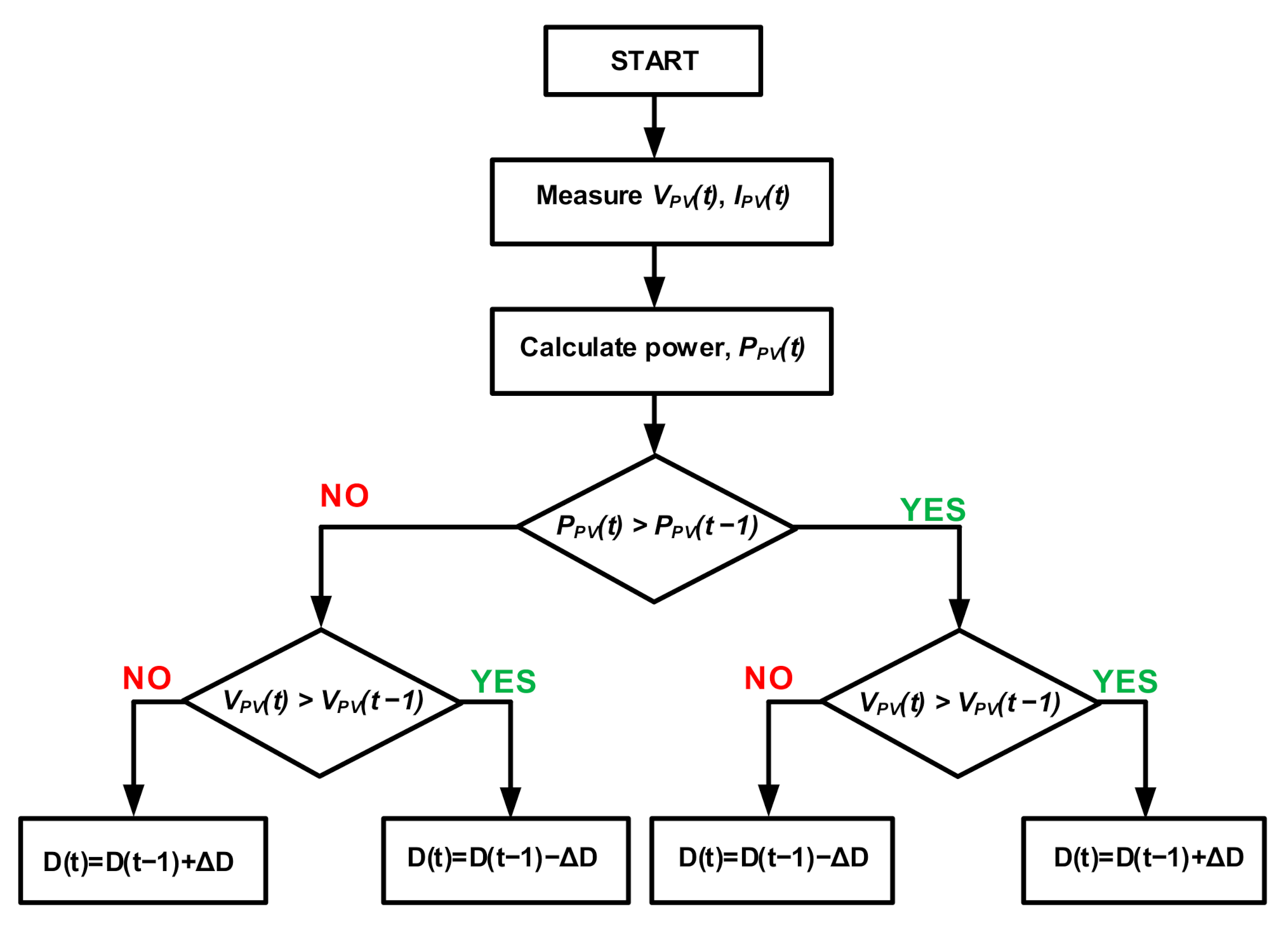
Figure 9 presents the principle of control strategy, which is based on the flow chart for the P&O algorithm. In the operation of the P&O algorithm, the principle of incremental increasing/decreasing of the array voltage is applied in order to find the maximum point of output array power [
31]. The PV array voltage is periodically perturbed, and then the output power of PV is compared with that of the previous cycle of perturbation. According to the presented flow chart, when the PV power and PV voltage are increased at the same time, the perturbation step size ΔD will be added to the duty cycle D of DC/DC boost converter [
23,
25,
30,
33,
34]. However, when the PV power increases and PV voltage decreases, the perturbation step size ΔD will be subtracted from the duty cycle D for the next cycle of perturbation. This process of searching will be repeated until MPP point will be reached.
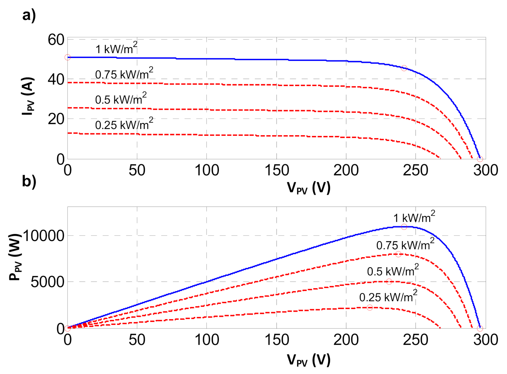
The P&O MPPT algorithm is suitable for use in PV control systems, because of its simple structure and because it requires only two parameters of PV array: Photovoltaic voltage
VPV and photovoltaic current
IPV. The certain disadvantage of the P&O algorithm is the possibility of power oscillation at the state, when the algorithm is almost reaching the MPP. To avoid power oscillations, the right choice of step size for the next time cycle is very important. In the literature, many other improvements of P&O algorithm are also considered [
23,
31].
4.2. Control of Bidirectional DC/DC Converter for Battery System
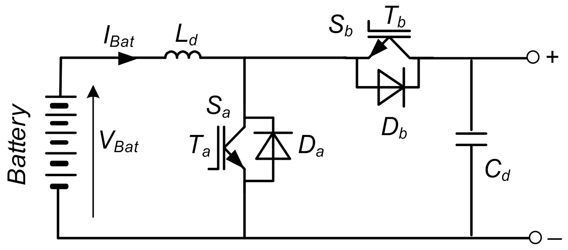
For the conversion of energy in the BES system, the bidirectional flow of electrical energy is required. For this aim, in the control system, the DC/DC current reversible chopper has been applied. The scheme of the considered converter is presented in
Figure 10.
The DC/DC converter is comprised of two controlled switches, Sa and Sb, inductor Ld, and filter capacitor Cd. The converter can be treated as the combination of two basic chopper circuits, the step-down chopper and the step-up chopper. The bidirectional DC/DC converter enables the operation in the power mode with charging the battery and the operation in the regenerative mode with discharging the battery. It is obtained by the suitable control system, which generates two control signals for two controlled transistor switches of the converter.
In
Figure 11, the control scheme of switches of bidirectional DC/DC converter for the BES system has been presented [
11]. For the control of switches, the adequate control loop has been applied. The reference value of the required battery power
PBat* is calculated as the difference of the current demand of load power
PLoad, the wind turbine generated power
PWT, and photovoltaic generated power
PPV. The obtained value of the reference battery power
PBat* is then divided by battery voltage
VBat. In this way, the reference battery current
IBat* is determined. In the control system, the reference battery current
IBat* is compared with the measured battery current
IBat. The error signal is given to the PI controller. The reference signal of duty cycle D1 of DC/DC bidirectional converter is determined as the output value from the PI controller. In the realized control system, the additional limited block was introduced in order to protect the battery against the flow of power greater than the maximum allowable power.
Moreover, in the realized control system, the additional algorithm for battery protection from excessive overcharging and excessive deep discharging has been implemented. The State of Charge (SOC) of the battery has the important role in increasing the battery lifetime [
17,
28]. When the SOC values of the battery are not in the proper range, the switching signals of the converter are blocked, and the bidirectional DC/DC converter is out of operation.
4.3. Control of Wind Turbine with MPPT and PMSG with Machine Side Converter
In order to achieve the wind turbine operation at the conversion of maximum mechanical power from the wind, the algorithm of Maximum Power Point Tracking (MPPT) should be included in the control system. In the literature, several methods of MPPT have been considered [
6,
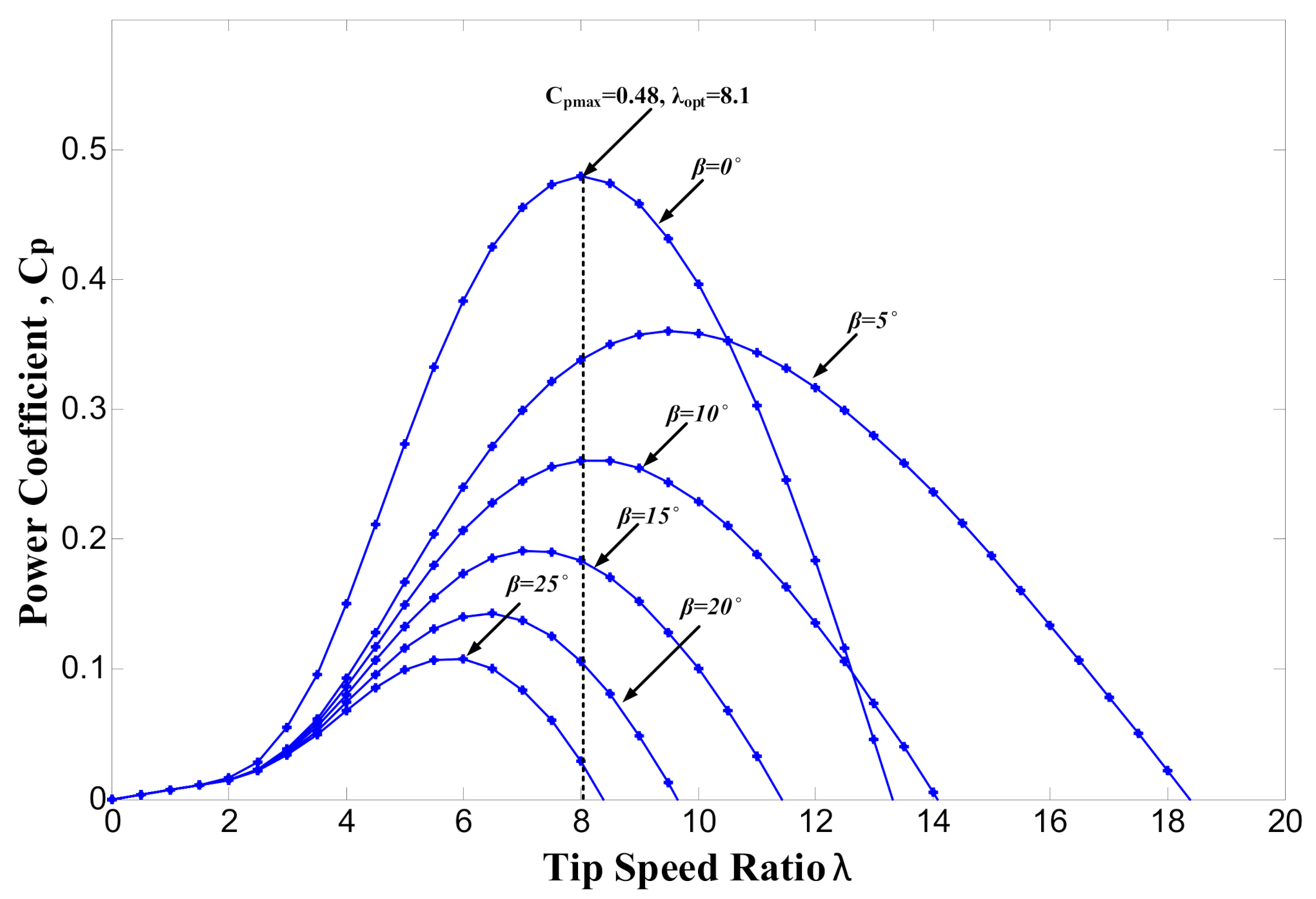
8]. These MPPT methods are based on calculation algorithms or on search algorithms techniques. The search algorithms are precise, but they need quite a long period of time in order to find final solution. In study of complex HRES systems the calculation algorithms of MPPT are preferable. The very often used in simulations calculation algorithm is based on using the MPPT method with optimal Tip Speed Ratio (TSR).
In the TSR control, the turbine should be operated at optimum value of rotational speed
ωopt. It is realized by controlling the turbine speed in order to follow the optimum speed
ωopt. On the base of Equation (2) and
Figure 4, the reference value of rotational speed
ωref is determined by the choice of optimal tip-speed ratio
λopt. The reference rotational speed
ωref of the wind turbine rotor is equal to an optimal value of the rotational speed
ωopt of the wind turbine rotor, which is specified as follows:
The above equation determines the principle of TSR control for tracking the peak power points of wind turbine. While maintaining the constant optimal value of λopt, the reference turbine rotational speed ωref should be changed proportionally to the current wind speed vw.
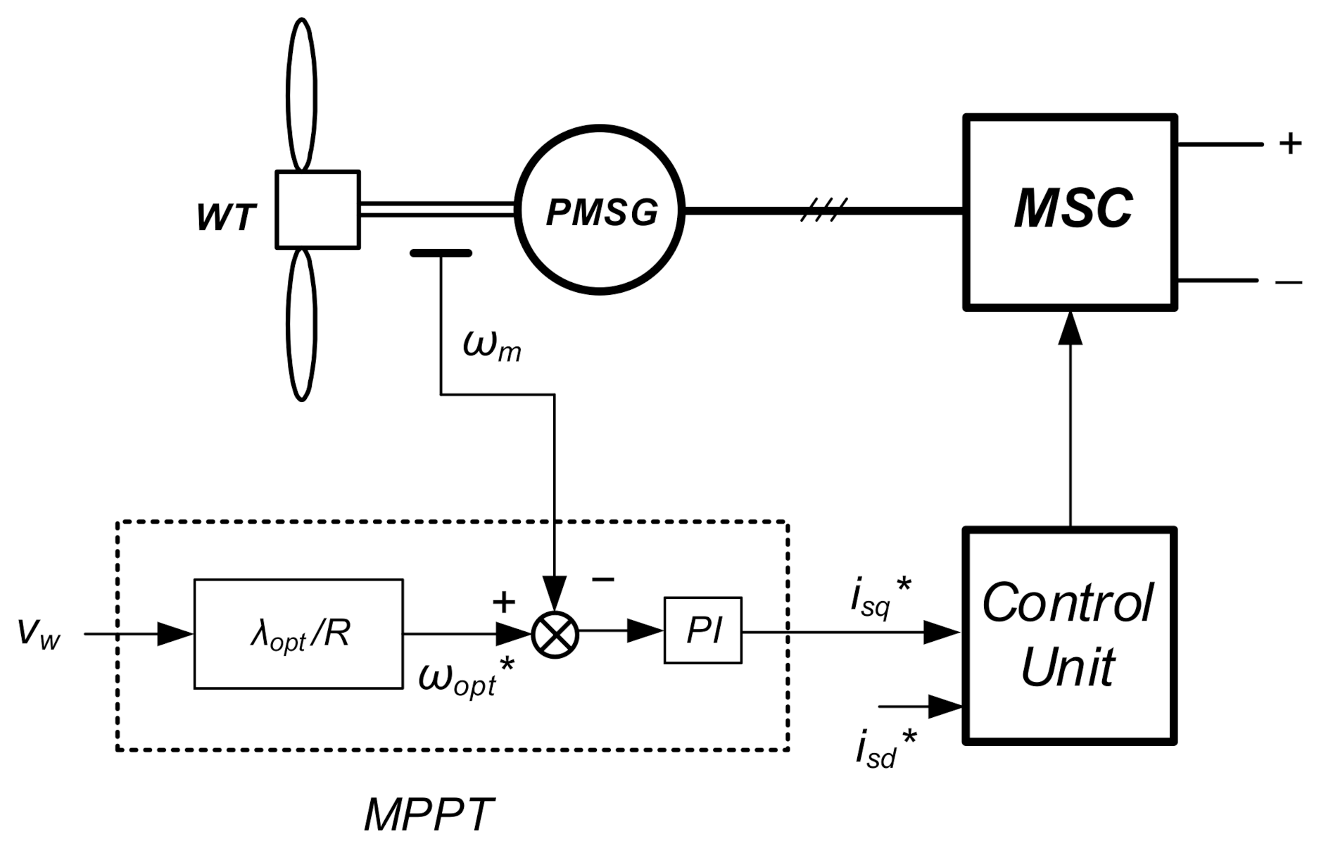
In this paper, the MPPT algorithm based on the choice of optimal value of TSR has been implemented. The TSR control of MPPT for the wind turbine is presented in
Figure 12. In the control systems, the optimal turbine rotational speed is calculated through TSR block and as the reference speed
ωref is compared with the measured rotational speed
ωm of the turbine rotor. The obtained error signal is given to the PI controller. The output control signal of the speed control loop is the reference signal
isq* of
q-component of stator current vector, which determines the electromagnetic torque of the PMSG.
The presented TSR algorithm of MPPT is simple, precise, and useful for analytical and simulation studies. However, the practical applications of this algorithm are limited because of the difficulty of accurate measurement of the wind speeds acting on the turbine blades.
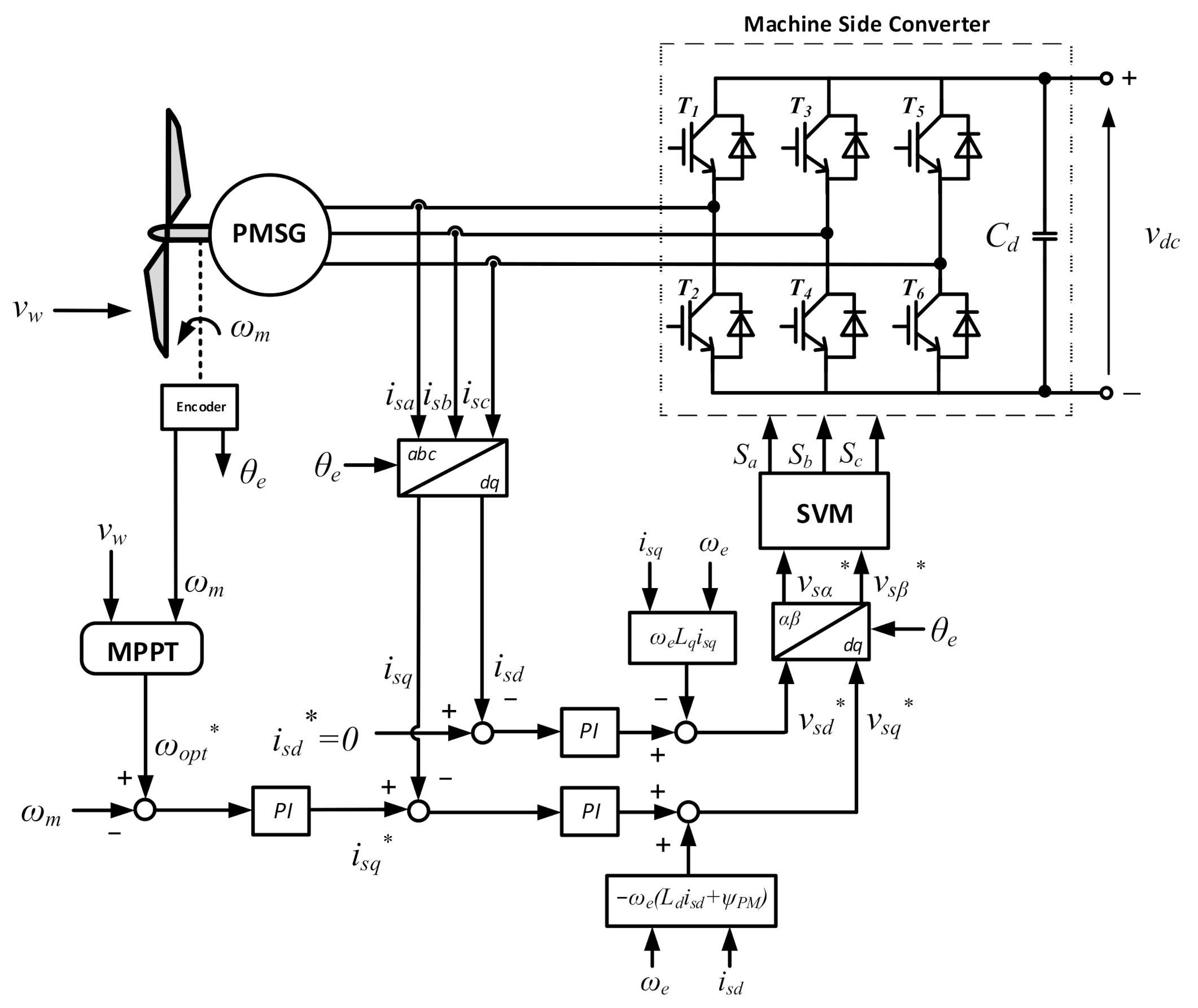
The considered Machine Side Converter (MSC) in the system is the three-phase AC/DC converter of the conventional topology of two-level voltage inverter. The control of PMSG with MSC is based on vector control with application of Rotor Field Oriented Control (RFOC).
Figure 13 shows the detailed scheme of RFOC control with application Space Vector Modulation (SVM) for MSC [
6,
18].
In the presented control scheme, there are three control loops. The aim of the outer control loop is the control of generator rotational speed. Two inner control loops are designed for control of individual components of the stator current vector.
The PI controller in the outer control loop provides by control, that the generator speed is following the reference course of optimal speed ωopt of the wind turbine, at which the maximum power of wind turbine is produced. The reference signal isq* of the q-component of stator current vector is generated as the output control signal of the speed control loop. The reference signal isq* determines the desired electromagnetic torque of PMSG.
Both stator current vector components: isd and isq are regulated thorough two inner control loops with PI controllers. In the control system, the method of zero d-axis stator current control is realized, and for this reason, the reference component isd* of stator current vector is set to zero value. As a result of this, the stator current vector will be equal only to its q-axis component isq. With isd = 0, the generator electromagnetic torque is proportional to the q-axis current component isq. The stator current reference isq* is achieved in the control system by using the operation of the MPPT block. The reference dq-axis components isd* and isq* of stator current vector are compared with the real current components isd and isq, obtained from measurement and transformation of real stator phase currents. As the result of the comparison operation, the error control signals are generated and sent to the individual PI controllers. In the control system, the decoupling blocks have also been implemented in order to assure high control performance. The output signal from each decoupling block is added to the output signal of the corresponding controller. In this way, the resultant control signals that form the dq-axis reference components vpd* and vpq* of the stator voltage vector are obtained. These reference voltages are then transformed from the rotating d-q-system to the stationary α-β-system, and are sent to the block of Space Vector Modulation (SVM) of the MSC.
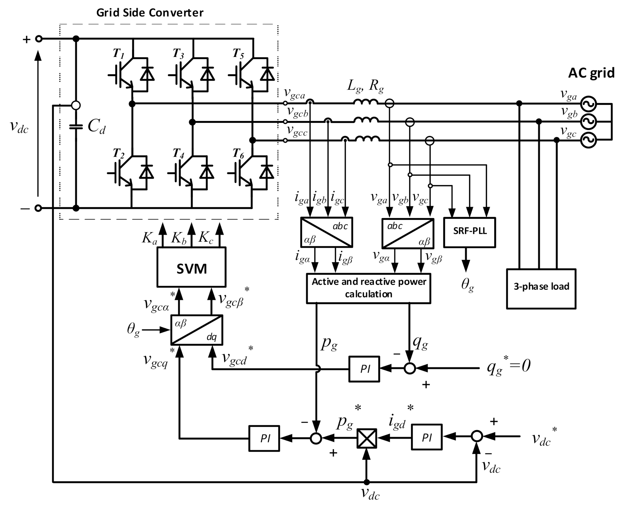
4.4. Control of Grid Side Converter
The Grid Side Converter (GSC) is the three-phase DC/AC converter of the conventional topology of two-level voltage inverter. For the control of GSC the modern control method based on Direct Power Control (DPC) with SVM modulation has been implemented. The main aim of the GSC is to perform the basic control tasks in the system. These tasks include the control of DC link voltage of the GSC and control of the instantaneous active and reactive power delivered to the AC grid. The detailed control scheme of DPC-SVM system has been presented in
Figure 14 [
6,
20].
There are three control loops with PI controllers applied in the control scheme of DPC-SVM for the GSC. The outer control loop regulates DC link voltage of the GSC and DC bus of HRES. Two inner control loops regulate the active and reactive power transferred to the loads and to the AC grid. The measured values of active and reactive power are estimated in special blocks and compared next with the reference values. In the common operation of the control system, the reference of reactive grid power qg* is set to zero in order to perform the system operation at the unity power factor. The reference of active grid power pg* is calculated on the base of multiplication of the measured DC voltage vdc of the converter and the reference value of grid current vector component igd*. The reference value of grid current vector component igd* is obtained from the outer control loop. The output signals from the inner PI controllers determine the reference grid voltage vector components vgcd* and vgcq* for the control of GSC. After transformation of these reference voltages from rotating d-q-system to the stationary α-β-system, the control signals are obtained, which are sent to the block of SVM of GSC. For the determining the angle θg used for the transformation of reference voltages vgcd* and vgcq* from d-q-system to the α-β-system, the grid voltages are measured. For the determination of the angle θg of grid voltage vector vg, the PLL method and control circuit have been implemented.
5. Energy Management Strategies
5.1. General Conditions of Energy Management
In the HRES system, the conditions for adequate flow of the electrical energy should be fulfilled. Therefore, the adopting of special energy management strategy (EMS) is essential to ensure proper operation of the system and reduce the costs of its operation. The aim of the energy management system is to maintain the balance between the energy produced by the energy sources and the energy demanded by the electrical loads and energy storage, while protecting the storage units from excessive charge or discharge, and including the possible exchange of energy with the electrical grid. The energy management strategy can be also integrated with special optimization system in order to ensure the continuity of load supply and to decrease the cost of energy production. Various approaches and techniques have been used to develop a successful energy management strategy. Several studies discussing the issues connected with energy management in HRES are presented in [
15,
16,
35]. In [
15], a DC-coupled wind/hydrogen/supercapacitor hybrid power system is studied. A novel special HRES system, designed to sustainably meet a dynamic electricity demand of a membrane bioreactor, is considered in [
16].
In the developed approach to energy management, the grid-connected hybrid renewable systems and the stand-alone hybrid renewable energy systems were included. For this aim, the special power management algorithm (PMA) was developed to operate both the photovoltaic energy system and the wind energy system at the maximum power they can generate under various environmental conditions. Therefore the energy management strategy includes the MPPT systems of wind and PV energy, battery energy storage, utility connection, and load switching. In order to maintain a long life-time of the battery, the State of Charging (SOC) of the battery is also controlled in the developed energy management strategy. The operational value of SOC is kept between the minimum value SOCmin (about 20%) and the maximum value SOCmax (usually about 80–90%). In addition, in the energy management strategy, it was concluded that during battery charging and discharging processes, the maximum permissible power load of the battery may not be exceeded.
On the base of the system architecture presented in
Figure 3, the equation of power balance of HRES used in energy management strategy can be described in the following form:
where:
PWT—output power of WT and PMSG;
PPV—the power delivered by PV system;
PBat—the battery power;
PGrid—the grid power; and
PLoad—the electrical load power.
Equation (22) is the algebraic equation, in which some power components can have various signs, depending on the condition, whether the considered power component is delivered or taken away from the common DC bus. The equation was formulated at the assumption of neglecting of power losses in the system and for the condition of operation in steady-states. The equation has a general form and can be used for the analysis of both grid-connected HRES and stand-alone HRES. For stand-alone HRES, the component of grid power PGrid in this equation should be omitted.
The conditions of energy management strategy were mathematically modelled in the program block of the Power Control Unit (PCU) and were implemented in Matlab-Simulink software. The developed management strategy ensures the power balance between the energy sources and loads, and protects the storage battery from overcharge or deep discharge. In the PCU the presented below power-balancing algorithms for different architectures of HRES were implemented. In the algorithms the possible operating states of HRES were included and considered.
5.2. Energy Management Strategy for Grid-Connected HRES
The total generated power from the renewable energy sources: the wind turbine power PWT and the PV power PPV is treated as the primary supply power, that has the priority in satisfying the load demand over that provided by utility grid. It was assumed, that the energy consumption from the grid should be avoided because it requires additional payment and costs. For this reason, the using of energy from the utility grid is put at the end of the list of priorities.
If the total power generated by WT and PV systems (PWT + PPV) is greater than the load demand PLoad, the surplus power PSur = PWT + PPV − PLoad has the priority in charging the battery with the power PBat. The battery can be charged until it will be fully charged. The whole surplus power can be delivered to the grid only in the case when the battery was fully charged PGrid = PSur. Because the battery can be charged only with the limited maximal power PBatmax, when the surplus power is greater than PBatmax, then the battery is charging with its maximal power, and only the rest of surplus power is returned to the utility grid PGrid = PSur − PBatmax.
If the total power generated by WT and PV systems (PWT + PPV) is lower than the load demand PLoad, then deficit power PDef = PLoad − (PWT + PPV) will occur in HRES. The battery has the priority, and at discharging is able to deliver the addition to the power demand of the load. However, when the battery is fully discharged, the deficit power must be completely delivered from the grid. Because the battery can be discharged only with the limited maximal power PBatmax, then when the deficit power is greater than PBatmax, the battery is used at discharging with maximal power, and the rest of deficit power must be received from the utility grid PGrid = PDef − PBatmax.
The general block diagram presenting the developed power management strategy for grid-connected HRES is presented in
Figure 15.
5.3. Energy Management Strategy for Stand-Alone HRES
The energy management strategy for stand-alone HRES is similar to the strategy applied in the grid-connected HRES. A significant difference is the lack of access to the utility grid and not the possibility to draw power from the grid and no feed-in power to the grid.
If the total power generated by WT and PV systems (PWT + PPV) is greater than the load demand PLoad, the surplus power PSur will charge the battery when the condition is fulfilled PSur ≤ PBatmax. The battery can be charged until it will be fully charged. After the battery is fully charged or PSur > PBatmax, the excess power PSur cannot be stored, and because of this, it should be limited. It can be obtained by decreasing the generation of renewable energy by throwing control systems from keeping operation at maximum power points or simply by switching off selected sources of renewable energy generation. Excess power can be also dumped in some additional energy loads specially connected to the system in this case.
If the total power generated by WT and PV systems (PWT + PPV) is lower than the load demand PLoad, than there will be deficit power PDef in HRES. The battery will be discharged in order to reduce or compensate for the power deficit. This state is possible only in the determined period of time because of the limited battery capacitance. The battery capacitance should be designed for the projected period of no energy production or a reduced value of generated energy. It is also recommended to divide the used power loads into critical loads, which cannot be turned off and into non-critical ones, which can be turned off when the amount of generated energy in the system is insufficient. Another possible solution in this case is to use an additional energy source, e.g., an electric generator system driven by an internal combustion engine.
6. Simulation Results
The mathematical models of individual parts of the hybrid renewable energy system (HRES) and the applied control systems have been implemented in the simulation program, which was formulated in a MATLAB/Simulink environment. Digital simulation studies were performed for the converter systems with a wind turbine, PMSG, PV panels, and battery bank. The data and parameters used in the simulation studies are presented below:
Data and parameters of the wind turbine system: Rated power, PWT = 20 kW; rotor radius, R = 4.4 m.
Data and parameters of PMSG generator: Rated power, Pe = 20 kW; stator resistance, Rs = 0.1764 Ω; stator dq-axis inductances, Ld, Lq = 4.48 mH; rated speed, ns = 211 rpm.
Data and parameters of PV array: Rated power, PPV = 12 kW; number of panels in series, Ns = 5; number of parallel strings, Np = 10; open circuit voltage, Voc = 59.26 V; short circuit current, Isc = 5.09 A.
Data and parameters of battery system: Rated capacity, CBat = 75 Ah; single module voltage, VBat = 12 V; number of modules in series, NBs = 25; rated voltage of battery, VBat = 12 V × 25 = 300 V; rated power of battery, PBat = 5 kW.
Many simulation studies were conducted to show performance of the HRES system under various conditions. The chosen simulation results are presented in
Figure 16,
Figure 17,
Figure 18,
Figure 19,
Figure 20,
Figure 21,
Figure 22,
Figure 23 and
Figure 24. For the purpose of shortening the simulation times, it was assumed that the changes of considered consecutive operation states in the system are quite fast and are performed in short time intervals.
In
Figure 16,
Figure 17,
Figure 18 and
Figure 19, the simulation results of selected operation states of the wind turbine system with PMSG and MSC have been presented. In
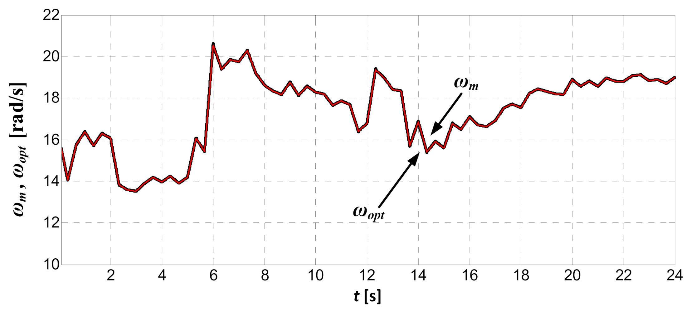
Figure 16, the assumed wind speed variation during the simulation time period of 24 s is shown. In
Figure 17, the waveforms of optimal reference angular speed
ωopt =
ωref and measured angular speed
ωm of the wind turbine rotor and the rotor of PMSG are presented. The performed studies confirm, that the waveform of turbine angular speed
ωm is accurately adjusted to the waveform of optimal referenced speed
ωopt. The applied MPPT algorithm ensures the determination of the reference speed
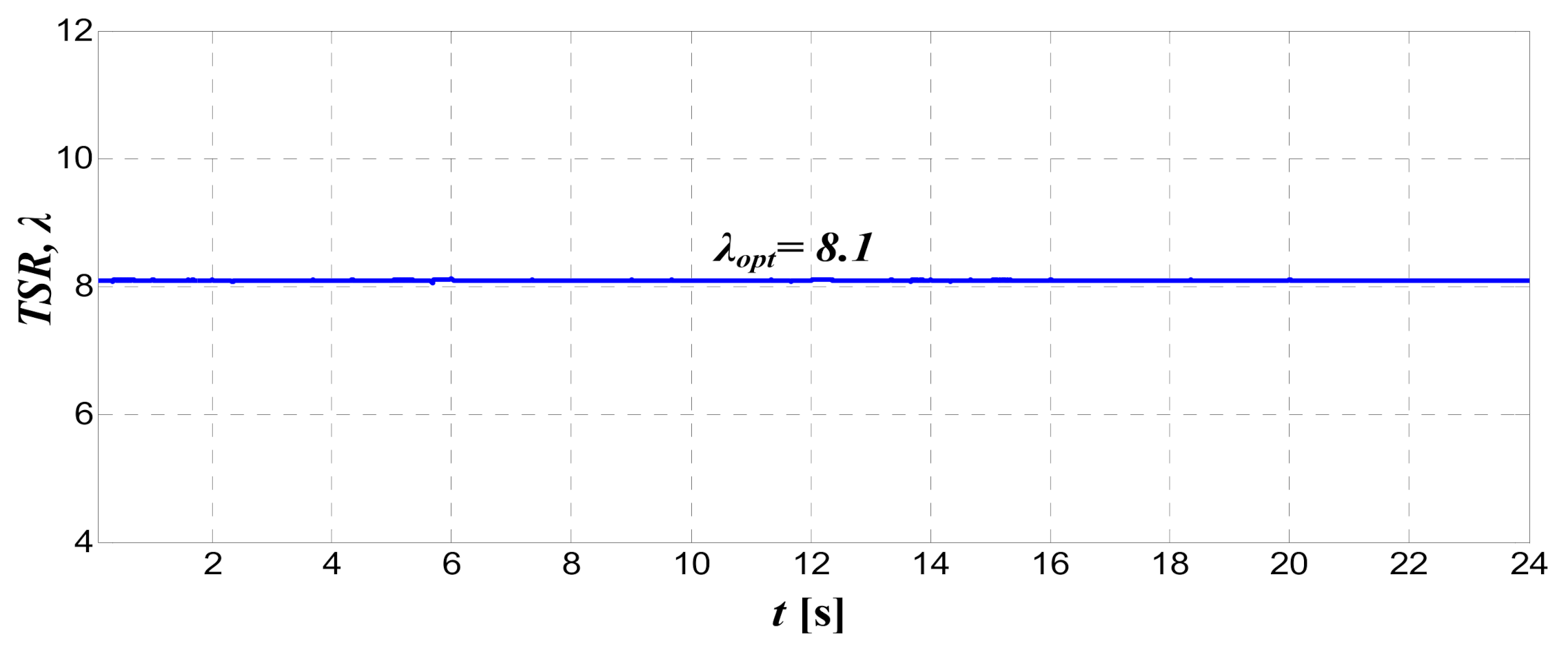
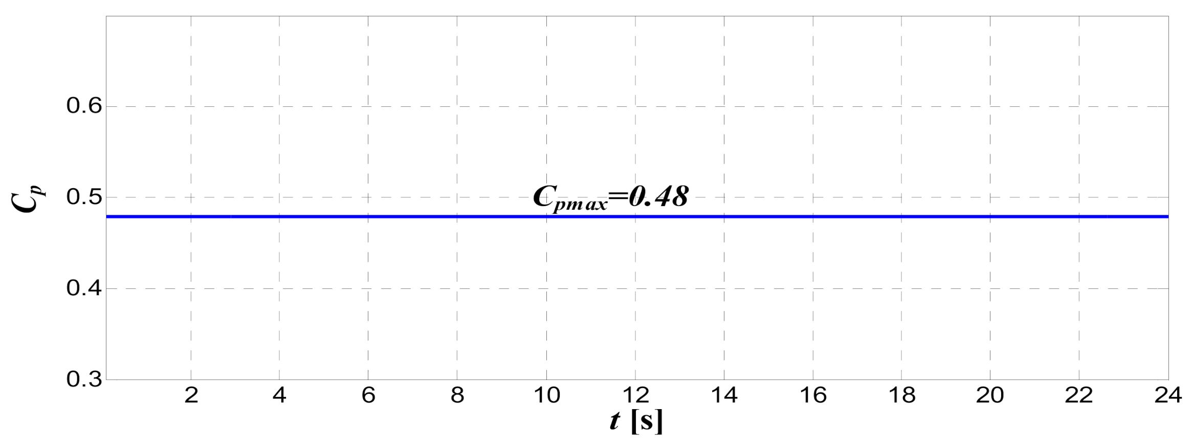
ωopt. For these assumed conditions of realization of MPPT, the wind turbine should be in the operation at a constant optimal value of tip speed ratio
λopt and at a constant maximum value of turbine power coefficient
Cpmax. The obtained courses of tip speed ratio
λ and turbine power coefficient
Cp at various wind speeds have been presented in
Figure 18 and in
Figure 19, respectively. On the base of these figures, the proper operation of MPPT algorithm of the wind turbine can be confirmed. Even, if there are large changes of wind speeds, the optimal and constant values of tip speed ratio
λ and power coefficient
Cp have been reached.
In
Figure 20 and
Figure 21, the selected simulation results of studies of PMSG and MSC with the control system, based on the RFOC method are presented, respectively.
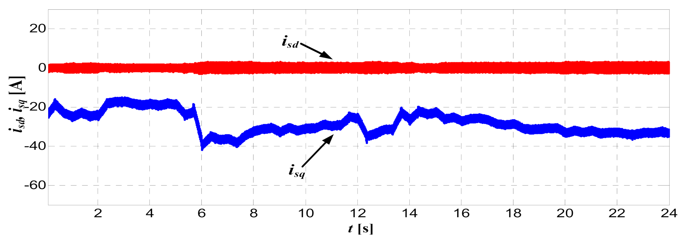
The courses of components
isd,
isq of stator current vector of PMSG have been presented in
Figure 20. On the base of these courses, it can be stated that the component
isd of stator current vector is almost exactly set by the control system to zero value
isd = 0. This condition is optimal and required for the proper operation of PMSG and for RFOC control of PMSG. On the base of the course, it can be stated that the component
isq of stator current vector is changing according to the waveforms of wind speed variations. The component
isq is responsible for the generation of electromagnetic torque
Te of the PMSG generator.
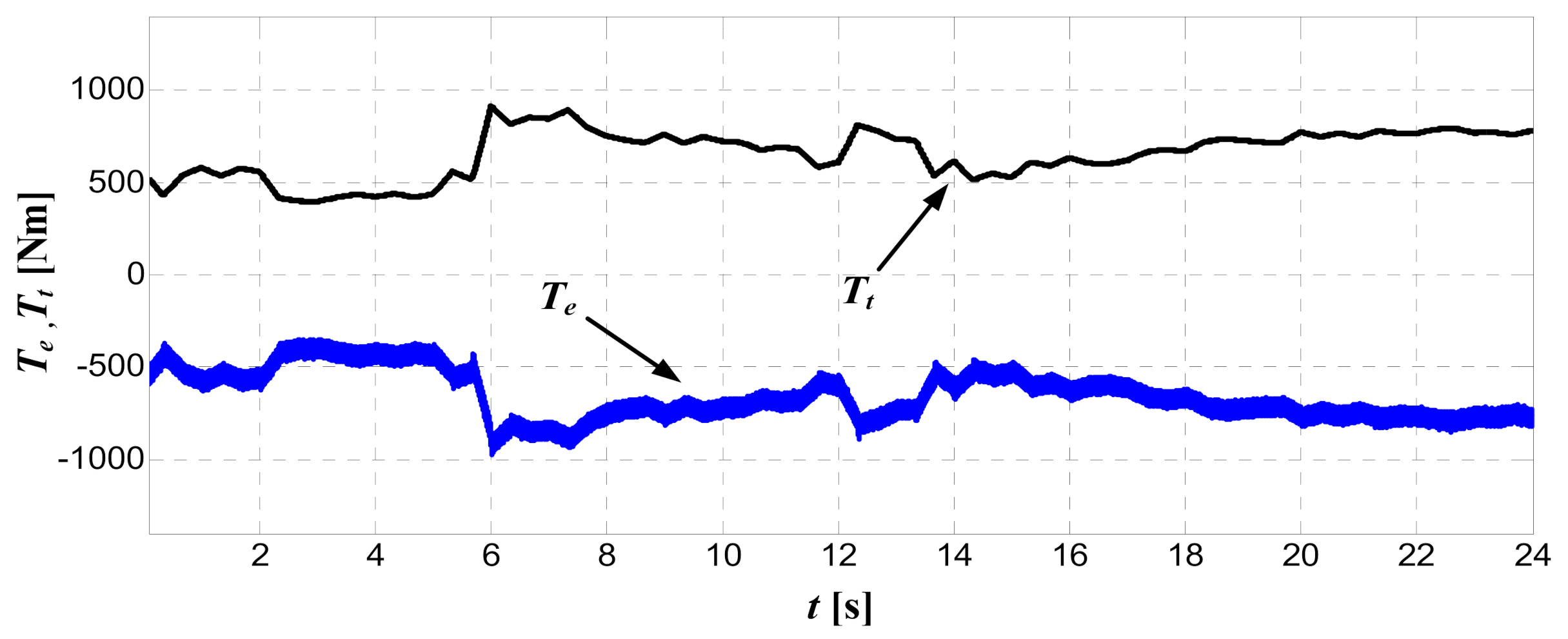
The runs of electromagnetic torque
Te of PMSG generator and mechanical torque
Tt of wind turbine have been presented in
Figure 21. On the base of comparison with
Figure 20, it can be confirmed that at RFOC control, the electromagnetic torque
Te of PMSG generator is proportional to the stator current vector component
isq.
The selected results of simulation studies of the DPC control system of GSC converter are presented in
Figure 22 and
Figure 23, respectively.
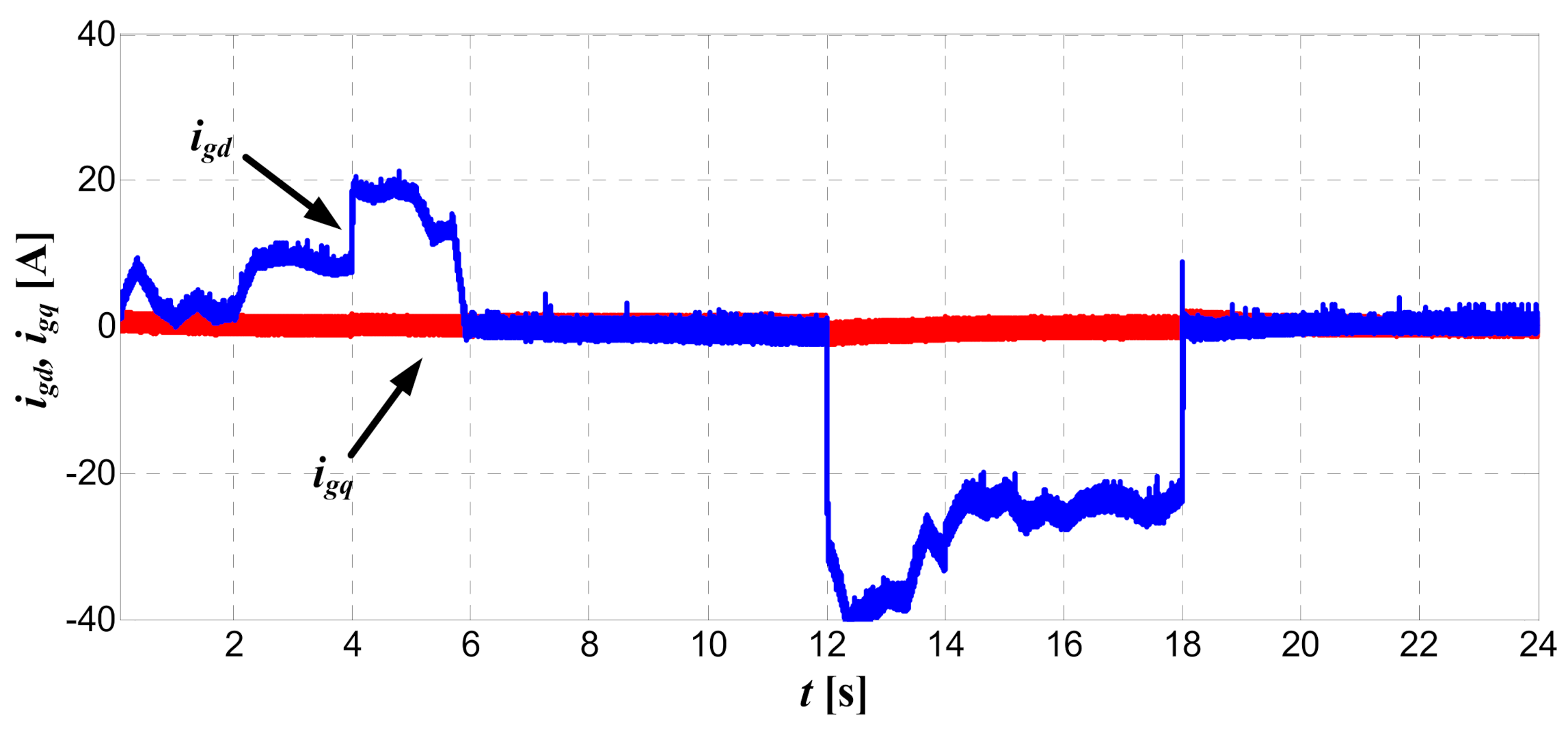
The courses of components
igd,
igq of grid current vector for GSC have been presented in
Figure 22. The component
igd represents the flow of the active power at the AC side of GSC. The power flow between the grid and the GSC converter can be bidirectional: Power can be transferred from the grid to the GSC or delivered from the GSC converter to the grid. At
igd > 0, the active power is transferred to the GSC and at
igd < 0 the active power is delivered to the grid. At
igq = 0, the reactive power is equal to zero, and the optimal operation of unity grid power factor is obtained. These conditions are properly met by the GSC control system, as shown in the
Figure 22.
The
Figure 23 presents the course of the voltage
vdc in the common DC link of the considered system of converters. It can be stated that the course of instantaneous voltage
vdc is kept practically on the constant level despite variations of wind speeds and changes of the power flows in the system. This is a confirmation of the high accuracy and quick operation of the control system.
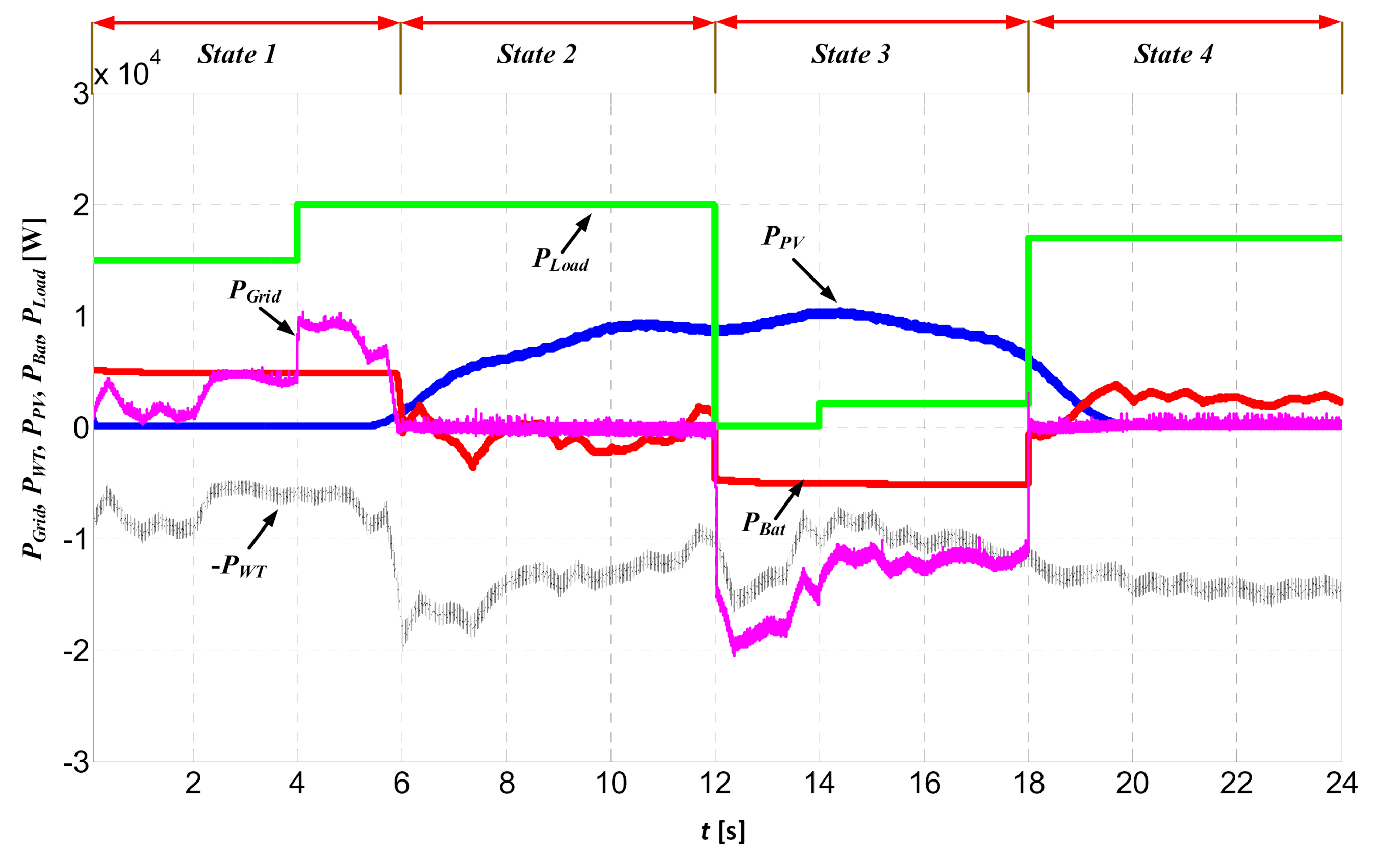
In the
Figure 24, the simulation runs of the power flows between particular parts of the considered Hybrid Renewable Energy System are presented. In the simulation, the complex HRES system presented in
Figure 3 and the simulation data given in
Section 6 have been included. For the simulation purposes, the operation time of the hybrid system was divided into four separate states: State 1, 2, 3, and 4. For individual states, different values of the load power consumptions as well as different levels of solar radiation and wind conditions were assumed, respectively.
In State 1, it is assumed that the PV system is out of operation (PPV = 0) and the load power consumption PLoad is high. Because the power of the wind system is smaller than the demand of load power (PWT < PLoad), the power shortage is supplemented by the battery, which operates at the rated power output in the discharging mode (PBat > 0). Despite these conditions, there is still a power shortage, which can only be eliminated by taking additional power from the grid (PGrid > 0).
In State 2, it is assumed that the PV system is in operation (PPV > 0), the wind system is in operation (PWT > 0), and the load power consumption PLoad is high. Because the sum of the power of the wind system and the power of the PV system is greater or equal to the load power (PWT + PPV ≥ PLoad), there is no need to take power from the grid (PGrid = 0). In the time intervals, when there is a surplus of generator and PV power over the load power, the battery works in the charging mode, i.e., with power consumption (PBat < 0). The system operation in this state is similar to the operation of the stand-alone system.
In State 3, it is assumed that the PV system is in operation (PPV > 0), the wind system is in operation (PWT > 0), and the load power consumption PLoad is small or equal to zero. Because the sum of the power of the wind system and the power of the PV system is greater than the demanded load power (PWT + PPV > PLoad), the part of surplus of generator and PV power over the load power is used for charging the battery with rated power (PBat < 0). The remaining part of the surplus power is the power recovered to the grid (PGrid < 0).
State 4 is similar to State 2, with the exception that the battery is operating in the discharging mode (PBat > 0).
The conducted simulation tests confirmed the purposefulness of using HRES systems and good operational properties of its subsystems. The overall structure of the hybrid energy system, consisting of a wind/PV/battery energy system, provides a good and reliable energy system. All sources of energy in the system can supply the power, and if any decrease in power occurs, it can be compensated through other sources. When the generated power is in excess, it can be stored in a battery or transferred to the AC grid. The considered renewable hybrid system can provide a continuous power supply to the load even in the case of low wind speeds or low value of solar irradiations.
7. Conclusions
In this paper, analysis and simulation studies of complex hybrid renewable energy system (HRES) have been performed. The considered system consists of wind turbine system with PMSG generator, photovoltaic panels system, and battery energy storage system. The multi-converter DC-coupled architecture of HRES was investigated.
The system is capable of ensuring the desired power flow to the loads under various operating conditions of renewable energy sources. The combined analysis of the considered HRES system is far more complex than separate study of individual components of the system, usually presented in the literature. The performed studies of the combined system can be treated as some original contributions of the authors.
The considered control algorithm of PMSG with machine side converter was based on Rotor Field Oriented Control with including TSR algorithm of MPPT. For control of the grid side converter, the Direct Power Control method has been applied. The applied DPC control is able to accurately maintain the DC link voltage value in accordance with the reference value and to adjust the desired power flows between the grid and the system. In the control of operation of the PV system, the MPPT algorithm based on P&O algorithm has been implemented. This algorithm allows us to obtain the maximum value of PV produced power for different levels of solar irradiation and ambient temperature.
The developed energy management strategies enable the proper operation of both the wind energy system and photovoltaic energy system under various environmental conditions while maintaining power supply demand of the load side at the required amount. In order to store the surplus power, the converter system with battery energy storage has been included and connected to the common DC link. This system accurately supports the wind and solar system in the case of high demand or low demand of the load power. The results of the performed simulations confirmed that the studied hybrid renewable energy system has appropriate technical and energetic properties and performances. The considered renewable hybrid system can provide a continuous power supply to the load even in the case of low wind speeds or low value of solar irradiations. In the case of surplus power from the wind turbine system or photovoltaic panels system, the excess power will be stored in the battery system. If the battery is fully charged, the excess power is fed back to the AC grid. Simulation results confirmed the good of the control system for the wind turbine with direct-driven PMSG, PV panels, and battery energy system.


