Article

Locational Marginal Pricing and Daily Operation Scheduling of a Hydro-Thermal-Wind-Photovoltaic Power System Using BESS to Reduce Wind Power Curtailment

by
Roberto Felipe Andrade Menezes
,
Guilherme Delgado Soriano
and
Ronaldo Ribeiro Barbosa de Aquino
*
Department of Electrical Engineering, Federal University of Pernambuco (UFPE), Recife 50740-533, Brazil
*
Author to whom correspondence should be addressed.
Energies 2021, 14(5), 1441; https://doi.org/10.3390/en14051441
Submission received: 15 February 2021 / Revised: 1 March 2021 / Accepted: 3 March 2021 / Published: 6 March 2021
(This article belongs to the Section A3: Wind, Wave and Tidal Energy)

Abstract

:
The Daily Operation Scheduling (DOS) gets new challenges while a large-scale of renewable energy is inserted into the power system. In addition to the operation, the power variability of these sources also causes a problem in the hourly pricing, represented here by Locational Marginal Pricing (LMP). Therefore, new applications, such as energy shifting, offer greater efficiency to the system, minimizing the negative effects caused by wind power curtailment (WPC). This paper shows the LMP formation in the DOS of the hydro-thermal-wind-photovoltaic power system with a battery energy storage system and the reduction of WPC. Here, the wind and photovoltaic power plants are designed to be dispatched, not mandatory, to be able to cut the generation, and the insertion of Distributed Generation is considered. Moreover, to solve the DOS problem, the interior-point method is used. Additionally, the DC optimal power flow, used to represent the DOS in addition to the representation of the electric grid, is modeled with an iterative approach. The analysis is made in an IEEE 24-bus system with data from Brazil. Lastly, the results of simulations are presented and discussed, demonstrating the effectiveness of the optimization to reduce the WPC, the total operation cost, and to provide the LMP curve.

1. Introduction

A power system operation with a large scale of renewable and intermittent sources may face new obstacles due to the dynamic performance of these sources during the day [1]. Some of these challenges, such as wind power curtailment (WPC), can be overcome by energy storage systems. In this regard, the pricing of hydro-thermal-wind-photovoltaic (HTWP) power systems and the introduction of a battery energy storage system (BESS) in the Daily Operation Scheduling (DOS) should be adopted and analyzed.
As seen in [2,3], for instance, a large scale of wind power generation is being integrated into the electricity grid in Brazil, and some problems may appear. One of them is the WPC, which cut off part of the available wind power generation. This problem occurs when there is congestion in the transmission grid or when the wind power exceeds the difference between the load demand and the minimum generation needed to maintain the stability of the system.
Other situations can cause the reduction of wind power generation in power systems with a significant number of wind farms. In addition to that, this paper explores the effect of Distributed Generation (DG) on the load demand curve and the ramp rate of the thermal power generation.
To reduce such a problem and improve power grid operation, the works of [4,5,6,7] apply BESS as an option. In this paper, the main application of BESS is to provide an energy time-shift in DOS.
With several sources in a complex power system, the DOS aims to establish a daily generation of each source to attend the load demand optimally and safely for each hour of the day, always for the next day. Furthermore, for the Brazilian national independent system operator, the DOS is a short-term problem with a horizon of up to 2 weeks, with hourly discretization. In this case, more details about the power system are provided, such as, for example, the constraints related to the generating machines and the electric grid, allowing greater reproducibility of the operation by the agents. Plus, the DOS problem can be represented by the DC optimal power flow (DCOPF) problem to explore properties of the real problem, as seen in [8].
This work is justified as a result of progressive energy market deregulation in some countries with a significant number of wind power plants (WPPs) in HTWP systems and continental-size, like Brazil. In this scenario, it is expected that the energy pricing policy is the main target, as seen in [9,10,11,12]. Then, an economic signal that should be applied to the day-ahead electricity market is the Locational Marginal Pricing (LMP). This signal is determined by the iteration between the source and the load demand, to get the supply of the cheapest energy source, considering losses and congestion of the transmission grid.
However, for HTWP systems, wind and photovoltaic electricity generation are rarely assessed for economic reasons or as a decision variable for the DCOPF problem, as seen in [13,14,15,16,17,18]. Therefore, this work considers the pricing in the DOS of HTWP systems with the wind and photovoltaic power generation as being variables of the problem and they are modeled with zero-cost. In addition to that, an analysis of the BESS effect to reduce the total operation cost and the WPC is proposed. Plus, the modeling of the DOS problem allows a partial supply of WPP (with power curtailment) due to the safe operation requirements [19,20,21].
The DCOPF, which represents the DOS problem, is solved using the predictor–corrector primal-dual Interior Point Method (IPM). To consider the loss of the system, a modified method, based on [22,23,24,25], is used to calculate the LMP. The test system is a modified version of the IEEE 24-bus that may represent Brazil.
In Brazil, the Energy Research Company forecasts that the average load demand will grow 3.2% per year until 2030, as seen in [26]. In this country, several generation ventures are being built to assist load demand, mainly wind farms. According to [27], the installed wind power generation capacity has increased from 25 MW in 2005 to 15.762 GW in 2020.
In this scenario, the northeast subsystem stands out with more than 85% of the wind power generation capacity, with the states of Bahia and Rio Grande do Norte contributing the most to this type of generation. Furthermore, since 2018 there has been a record of the entire subsystem being served by wind power energy and still being able to export a certain amount of energy [27].
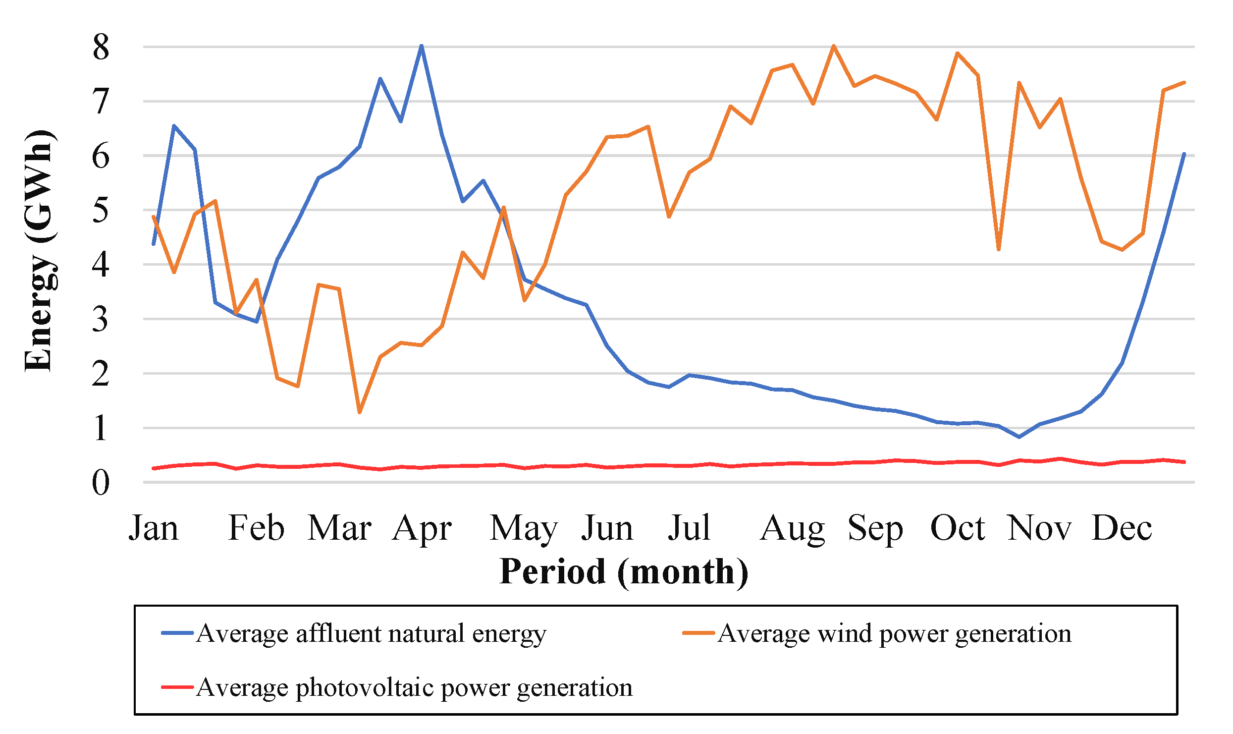
Moreover, there is a positive fact that the wind power seasonality in the northeast subsystem is complementary to the water profile. In Figure 1, it is possible to observe this complementarity through the curves of the average affluent natural energy and the average wind power generation in 2019 [27]. Although photovoltaic generation is not complementary to either of the two sources mentioned above, its growth has been gaining prominence in recent years. Solar irradiation in the northeastern region of Brazil does not have a characteristic variation over the year as the wind power generation, as can be seen in [28].
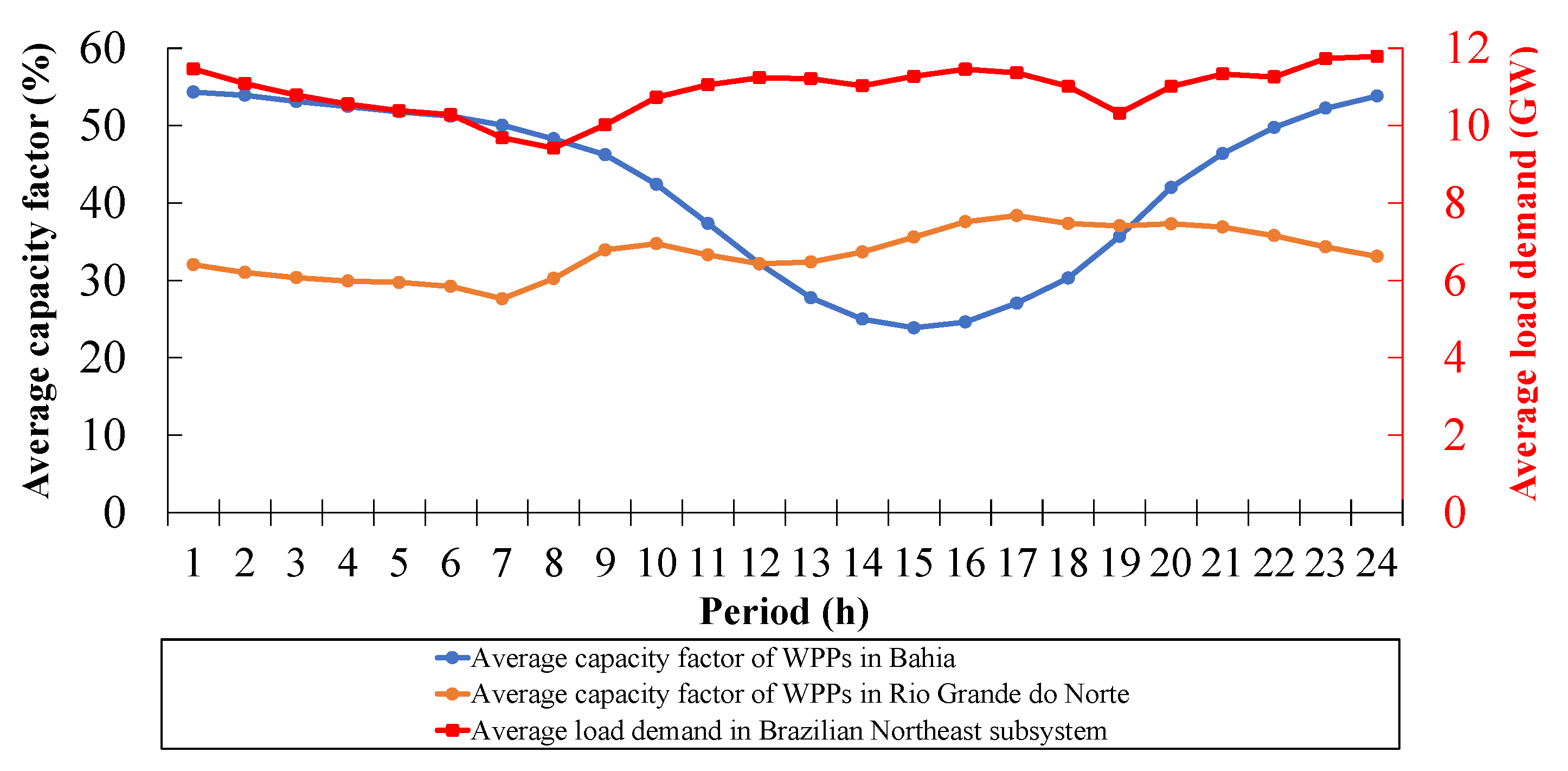
This complementarity is a reason that brings security to the energy supply. In addition, wind power generation is spread across the northeast subsystem, which causes a difference in wind behavior during the day. Figure 2 shows the average hourly capacity factor curves of WPPs in the states of Bahia (inland) and Rio Grande do Norte (coast) in 2019, as well as the daily profile of average load demand curve for the northeast subsystem, in the same year [27].
The WPC has been strongly discussed in the literature on thermal-based systems. Yet, for hydro-based systems predominantly, as in Brazilian ones, the power depends on river inflows and reservoir storage levels. In the driest period, this may cause a risk of energy deficit, as can be seen in [8,29]. Therefore, in this case, the priority is to use the available wind or photovoltaic power. Furthermore, the continental dimensions of Brazil and the fact that the power system is regionally connected make the country even more dependent on hydrological and wind regimes. This point causes an interdependence among the subsystems and is necessary to avoid WPC for energy security, economic and strategic reasons [18].
More specifically, the main contribution of this paper is to present an analysis in which the wind power generation, modeled as a variable and with the help of BESS, performs an efficient WPC in the DOS of HTWP systems. Thus, a new contribution is provided, since the analysis shown here may be an economical solution.
Following, in Section 2 is described the DOS formulation used in HTWP systems with BESS and the WPC, and it is shown how the losses were included in the DCOPF problem to calculate the LMP values by an iterative method. The studied cases and results are shown in Section 3. Finally, in Section 4 are presented discussions and the conclusion of the study, respectively.

2. Materials and Methods

The DOS problem aims to minimize the operation costs, and the decision variables are time-linking. In other words, the modeling used here is assembled so that the solution of the problem is found considering the variable for the first hour of the day and the last one. The mathematical formulation of the DOS problem considered here is described below.
Following, the t index represents each hour of the day, and the maximum length is T = 24 . In addition to that, the i index represents each bus of the system, and the Ω i is the set of buses.

2.1. Hydroelectric Power Plants

The operational limits of Hydroelectric Power Plants (HPPs) depend on the turbine flow limits and the levels of downstream and upstream, according to [30]. However, to simplify the problem, hydraulic variables are omitted in this model. This way, the operational limits of the HPPs are represented by constraints:
P i , m i n H P i , t H P i , m a x H i Ω i , t = 1 , 2 , , T ,
where P i , t H is the HPP dispatch at the bus i in period t; P i , m i n H and P i , m a x H are the minimum and maximum operating limits of the HPP at the bus i, respectively.

2.2. Thermoelectric Power Plants Constraints

The operational limits of Thermoelectric Power Plants (TPPs) are represented by constraints:
P i , m i n T P i , t T P i , m a x T i Ω i , t = 1 , 2 , , T ,
where P i , t T is the TPP dispatch at the bus i in period t; P i , m i n T and P i , m a x T are the minimum and maximum operating limits of the TPP at the bus i, respectively.
In addition to that, according to [30], maximum ramp rate constraints for the increase and decrease of TPP generation are enforced as operative features that couple two consecutive periods. Thus, in some cases, it is not possible to admit an abrupt variation in the power generated in short intervals of time. Mathematically, ramp rate constraints are modeled by:
R i P i , t T P i , t 1 T R i i Ω i , t = 1 , 2 , , T ,
where R i is the maximum ramp rate of the TPP at the bus i. In this formulation, we consider the ramp down and ramp up constraints to be the same value.

2.3. Wind Power Plants Constraints

Wind power generation has a dynamic behavior according to the location where the wind farms are installed. This variability promotes several studies to represent this generation as a variable of the model in the DOS problem. For this, it is considered the hourly wind power forecast is the maximum limit that this variable can achieve [18,31,32,33].
In addition, the operational limits, represented by the predicted wind power for each hour of the day, allow a partial or total WPC. This modeling may be considered in a regional context, as seen in [34,35,36]. Thus, the geographic diversification of WPP can smooth out the fluctuations in wind power generation, making it more predictable. Finally, the wind power variables and your limits can be represented by:
0 P i , t W P i , t , e x p W i Ω i , t = 1 , 2 , , T ,
where P i , t W and P i , t , e x p W are the wind power generation and the expected production at the bus i in period t, respectively.

2.4. Photovoltaic Power Plants Constraints

The power generation of a photovoltaic power plant (PPP) also has a dynamic behavior according to the location where the solar farms are installed. Therefore, here, it is considered the hourly solar power forecast as the maximum limit that this variable can achieve [37]. The photovoltaic power variables and the limits can be represented by:
0 P i , t P P i , t , e x p P i Ω i , t = 1 , 2 , , T ,
where P i , t P and P i , t , e x p P are the photovoltaic power generation and the expected production at the bus i in period t, respectively.

2.5. Battery Energy Storage Systems Constraints

As it was previously mentioned, the use of BESS can be an alternative to reduce the WPC. Therefore, when there is surplus wind power energy, the amount of energy that would be cut, now it can be stored. For this, the BESS acts as load demand, when there is an excess of wind power generation, and provide power injection, alternatively.
The stored energy helps to reduce peaks and valleys of the load demand curve. Thus, the BESS discharge energy quickly in some situations: when the hourly price is higher than when the energy had been stored; when the system requires additional power to meet the load demand; and when it is necessary to relieve the transmission system.
The characteristics of BESS were modeled here, such as proposed in [33,38,39,40]. The energy capacity of BESS is generally defined according to the type of technology used to conserve the energy, and the constraints are represented by:
E i , m i n E i , t E i , m a x i Ω i , t = 1 , 2 , , T ,
where E i , t is the energy stored at the bus i in period t; E i , m i n and E i , m a x are the minimum and maximum storage capacities at the bus i, respectively. The energy stored available is:
E i , ( t + 1 ) = 1 γ i E i , t P i , t D / η i P i , t C η i · Δ t i Ω i , t = 1 , 2 , , T , Δ t = 1 h ,
where γ i is the BESS self-discharge rate at the bus i; η i is the BESS efficiency at the bus i; P i , t D and P i , t C are the BESS discharging and charging at the bus i in period t, respectively.
Furthermore, the term State of Charge (SOC) defines, in percentage, the level of energy stored in BESS. The constraints of these variables are defined by:
S i , t = E i , t / E i , m a x i Ω i , t = 1 , 2 , , T ,
where S i , t is the SOC at the bus i in period t, and its limits, that increase the useful life of BESS, are defined by:
S i , m i n S i , t S i , m a x i Ω i , t = 1 , 2 , , T ,
where S i , m i n and S i , m a x are the minimum and maximum SOC of BESS at the bus i, respectively. This way, relating (8) and (9), it is possible to obtain new limits for stored energy through:
S i , m i n E i , m a x E i , t S i , m a x E i , m a x i Ω i , t = 1 , 2 , , T .
Finally, as can be seen in [40], the charging and discharging power variables can be related to the variable P i , t S , described by:
P i , t S = P i , t D P i , t C i Ω i , t = 1 , 2 , , T .
This is allowed since P i , t D * and P i , t C * are solutions of DCOPF problem, and:
P i , t C * P i , t D * = 0 i Ω i , t = 1 , 2 , , T .
Therefore, it is possible to represent charging and discharging limits separately in two variables, respectively, by:
0 P i , t C P i , m a x C i Ω i , t = 1 , 2 , , T ,
and
0 P i , t D P i , m a x D i Ω i , t = 1 , 2 , , T ,
where P i , m a x C and P i , m a x D are the BESS charging and discharging limits at the bus i, respectively.

2.6. Energy Balance Constraint

The energy balance constraint is responsible for supplying the load demand and guaranteeing the use of all energy generated. This constraint is defined by:
i Ω i P i , t H + P i , t T + P i , t W + P i , t S = i Ω i D i , t , t = 1 , 2 , , T ,
and
i Ω i D i , t = i Ω i D i , t , e x p G t , t = 1 , 2 , , T ,
where D i , t and D i , t , e x p are the net and expected load demands at the bus i in period t, respectively; G t is the DG in period t.
The DG is modeled here as a reduction in expected system load demand in a certain period. Thus, it is a generation that cannot be controlled by the power system, but we can use it with an expected daily curve.

2.7. Transmission Limits Constraints

The transmission system has constraints related to the system security that influence the operating decisions. In this work, the DC power flow is modeled using the Power Transfer Distribution Factors (PTDF) matrix [41], and it is represented by:
P T D F k , i = Δ F k / Δ P i i Ω i , t = 1 , 2 , , T ,
where P T D F k , i is the element of the PTDF matrix; Δ F k is the power flow variation at the k transmission line due the injected or extracted power Δ P i at the bus i; Ω k is the set of transmission lines.
In addition to that, the PTDF matrix contains the participation of power injection factors in the composition of the flows in the system transmission lines. This matrix can be defined by:
PTDF = Y · A A T · Y · A 1 ,
where Y is the primitive admittance matrix and A is the reduced system incidence matrix. Therefore, the inequality constraints that define the capacity of the transmission system are:
F k , m a x i Ω i P T D F k , i P i , t H + P i , t T + P i , t W + P i , t S D i , t F k , m a x k Ω k , t = 1 , 2 , , T ,
where F k , m a x is the capacity of the transmission line k.

2.8. Objective Function

The objective of the DOS problem is to minimize the total operating cost related to the fuel cost from scheduled TPP. However, it is necessary to define a priority order when the system is faced with the possibility to choose the energy provided from other sources. For HPP and BESS, the energy is considered with a null unitary cost. Therefore, a priority factor ϵ that the IPM will choose the WPP or the PPP as a priority source is proposed here. This technique was created to avoid the WPC and based on the environmental value of the water.
The priority factor ϵ is a value that does not interfere in the IPM to find the best solution. Then, the objective function of the problem may be represented by:
min Z = t = 1 T i Ω i c i P i , t T + ϵ P i , t W + P i , t P ,
where c i is the cost of fossil-fuel generator i, and it is adopted ϵ = −10 5 R$/MWh.

2.9. DCOPF with Losses and the LMP

In this subsection, the calculations of the system losses and the LMP for DCOPF are described. It can be done with an iterative method, but, different from what is described in [22,23,24,25], this work considers the dimension of the problem to achieve the solution.
To simplify the development of the method, the ramp rate and energy storage constraints are disregarded. In addition to that, the active power injection at the bus i in period t is represented by the new variable P i , t G defined by:
P i , t G = P i , t H + P i , t T + P i , t W + P i , t P + P i , t S i Ω i , t = 1 , 2 , , T .
Thus, (15) and (19) can be rewritten, respectively, as:
i Ω i P i , t G = i Ω i D i , t , t = 1 , 2 , , T ,
and
F k , m a x i Ω i P T D F k , i P i , t G D i , t F k , m a x k Ω k , t = 1 , 2 , , T .
Lastly, the active power injection limits are defined by the constraints:
P i , m i n G P i , t G P i , m a x G i Ω i , t = 1 , 2 , , T .

2.9.1. System Losses Evaluation

Most DCOPF studies ignore electrical losses. In these cases, the energy price and the congestion price follow a linear model with a null loss price. However, system losses need to be considered in LMP.
To represent the system losses, the components Marginal Loss Factor (MLF) and Marginal Delivery Factor (MDF) are used, which are defined, respectively, by:
M L F i , t = Δ P t L / Δ P i , t G i Ω i , t = 1 , 2 , , T ,
and
M D F i , t = 1 M L F i , t i Ω i , t = 1 , 2 , , T ,
where P t L is the total system losses that can be represented by:
P t L = k Ω k R k F k , t 2 , t = 1 , 2 , , T ,
where R k is the resistance of transmission line k.
Thus, we can represent the power flow through the PTDF matrix and obtain a new equation for the MLF:
M L F i , t = 2 k Ω k P T D F k , i R k F k , t i Ω i , t = 1 , 2 , , T .
In this case, the MLF can be positive or negative. When positive, it means that the increase of the power injection at bus can increase the system losses. When negative, the increased injection on the bus can reduce system losses.
It has been observed in [22] that the MDF may double losses. Furthermore, in the same work it is proved that, in this model, an offset should be the estimated total system losses. Therefore, (22) can be rewritten by:
i Ω i M D F i , t P i , t G = i Ω i M D F i , t D i , t P t , e s t L , t = 1 , 2 , , T ,
where P t , e s t L is the offset or total system losses.
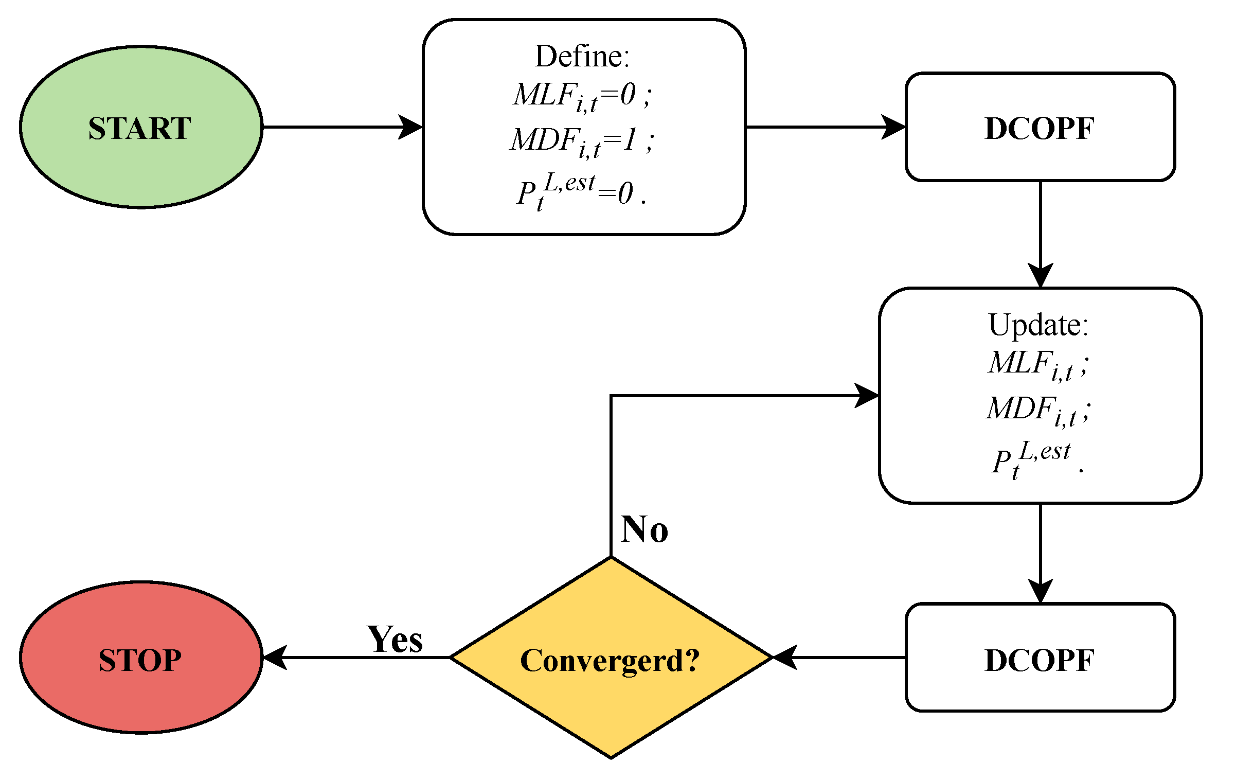
As shown in (28), the MLF values depend on the power flow in the transmission lines. To overcome this obstacle, the DCOPF problem is solved firstly without considering the MLF ( M L F i , t = 0, M D F i , t = 1 and P t L , e s t = 0). Therefore, with the solution found, the MLF values can be estimated and the DCOPF problem is solved again. This iterative process is repeated until the convergence stop criteria is reached. This entire process can be seen in the flowchart shown in Figure 3.
This method converges when:
P i , t , m G P i , t , ( m 1 ) G n ζ i Ω i , t = 1 , 2 , , T , ζ 10 3 ,
or
Z m Z ( m 1 ) n ζ i Ω i , t = 1 , 2 , , T , ζ 10 3 ,
where m is the iteration of the method and n is the the number of power system buses.

2.9.2. LMP Evaluation

After obtaining the DCOPF solution, the LMP can be calculated for any system bus from the Lagrange function L t :
L M P k , i = Δ L t / Δ D i , t i Ω i , t = 1 , 2 , , T ,
and
L t = i Ω i c i P i , t T + ϵ P i , t W + P i , t P λ t M D F i , t P i , t G D i , t + P t , e s t L k Ω k π k , t , m i n P T D F k , i D i , t P i , t G + F k , m a x k Ω k π k , t , m a x P T D F k , i P i , t G D i , t F k , m a x , t = 1 , 2 , , T ,
where λ t is the Lagrange multiplier related to the energy balance restriction; π k , t , m i n is the Lagrange multiplier related to the lower limit constraint; π k , t , m a x is the Lagrange multiplier related to the upper limit constraint.
Therefore, the LMP is calculated by:
L M P i , t = λ t M D F i , t k Ω k π k , t , m i n P T D F k , i + k Ω k π k , t , m a x P T D F k , i i Ω i , t = 1 , 2 , , T .

2.9.3. Fictitious Nodal Demand for System Losses

In (23), the power flow assumes a network without electrical losses, and the energy balance constraint, in (29), requires that the total generation be greater than the total load demand due to system losses. This leads to a mismatch effect, in a way that all losses appear in bus reference, as proven in [22]. Thus, it is necessary to represent the losses in the transmission lines.
To solve this problem, we implemented the Fictitious Nodal Demand (FND) concept to represent the electrical losses of the transmission lines connected to a bus. Hence, the FND is responsible for distributing system losses for each line of the network, aside from mitigating the mismatch effect. In this case, the losses of the transmission line are divided into two halves at respective buses. Thus, each half represents an increase in load demand at that bus. Finally, FND can be represented by:
F N D i , t = k Ω j 0 , 5 R k F k , t 2 i Ω i , t = 1 , 2 , , T ,
where Ω j is the set of transmission lines connected to bus i.
Now, the power flow will also be limited by the FND:
F k , m a x i Ω i P T D F k , i P i , t G D i , t F N D i , t F k , m a x k Ω k , t = 1 , 2 , , T .
Additionally, some steps in the iterative process, shown in Figure 3, are modified to integrate the FND: the second step, that initializes the marginal loss variables, should now consider F N D i , t = 0 , and the step of updating these variables should now evaluate F N D i , t .
Considering the DOS problem presented here, the next step is to verify solutions of operation and pricing.

3. Results and Discussion

The study is performed using a system based on the IEEE 24-bus power system [42]. In addition to that, the problem was solved by predictor-corrector primal-dual IPM designed in MATLAB R2018a on a desktop with an Intel Core i7-4790 and 32GB RAM.

3.1. Study System

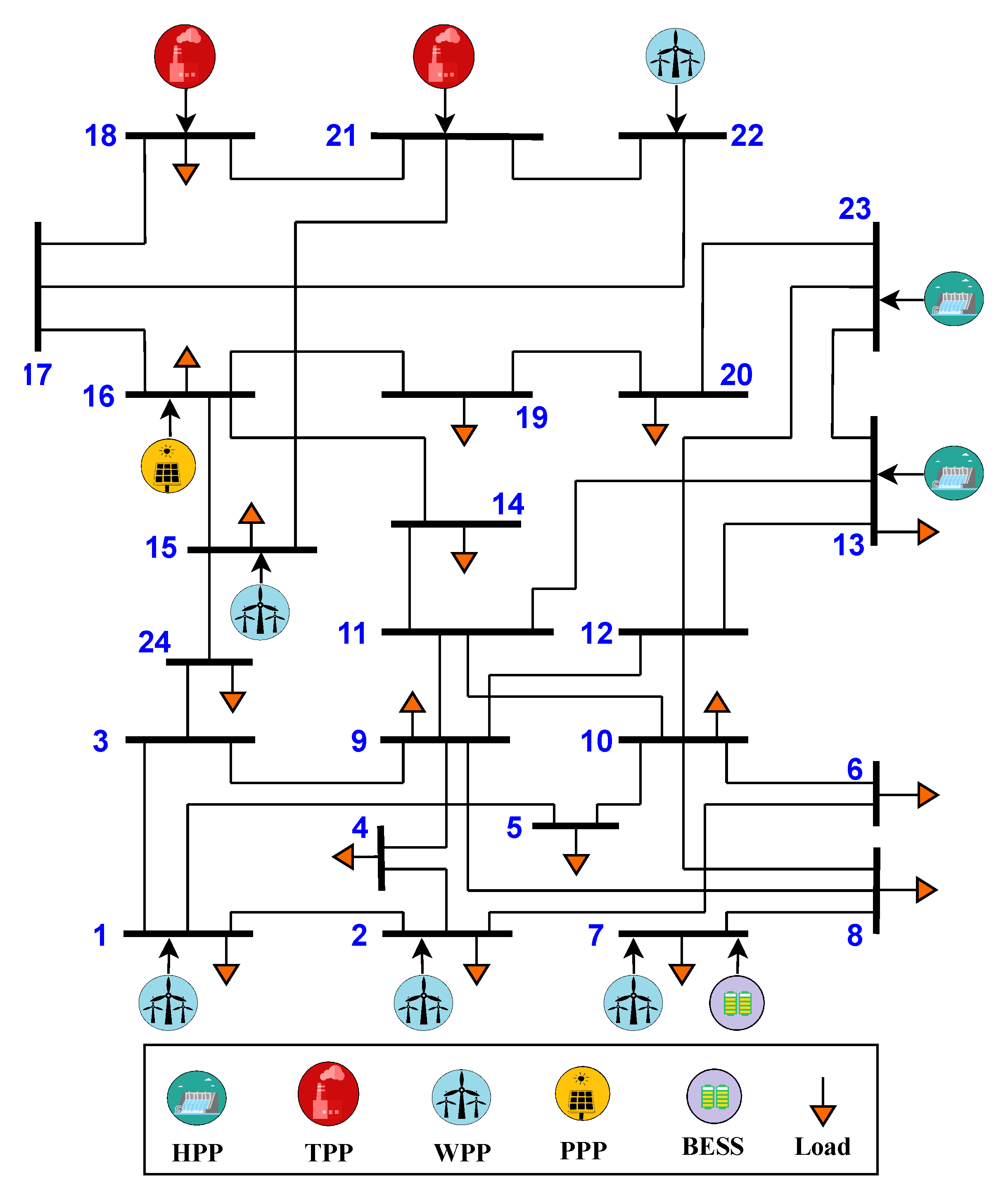
The pricing and DOS of HTWP systems are performed on an hourly basis. Therefore, the modified IEEE 24-bus power system was adjusted to better adapt to the actual conditions of Brazil’s northeast subsystem. This modification includes the data of the mix generation and decreased transmission lines capacity. Consequently, the modified system has two HPPs, two TPPs, five WPPs, one PPP, 34 transmission lines, and 17 load demand buses, and its diagram is shown in Figure 4.
A comparison between the power installed capacity of the original IEEE 24-bus and the modified one, with the respective sources, can be seen in Table 1. Furthermore, to match the total installed power capacity of the modified IEEE 24-bus power system with the original, the difference was distributed equally among the sources, as seen in Table 2.
The characteristics of the TPPs and the HPPs are based on real plants of the Brazilian power system [27], and they are reported in Table 3.
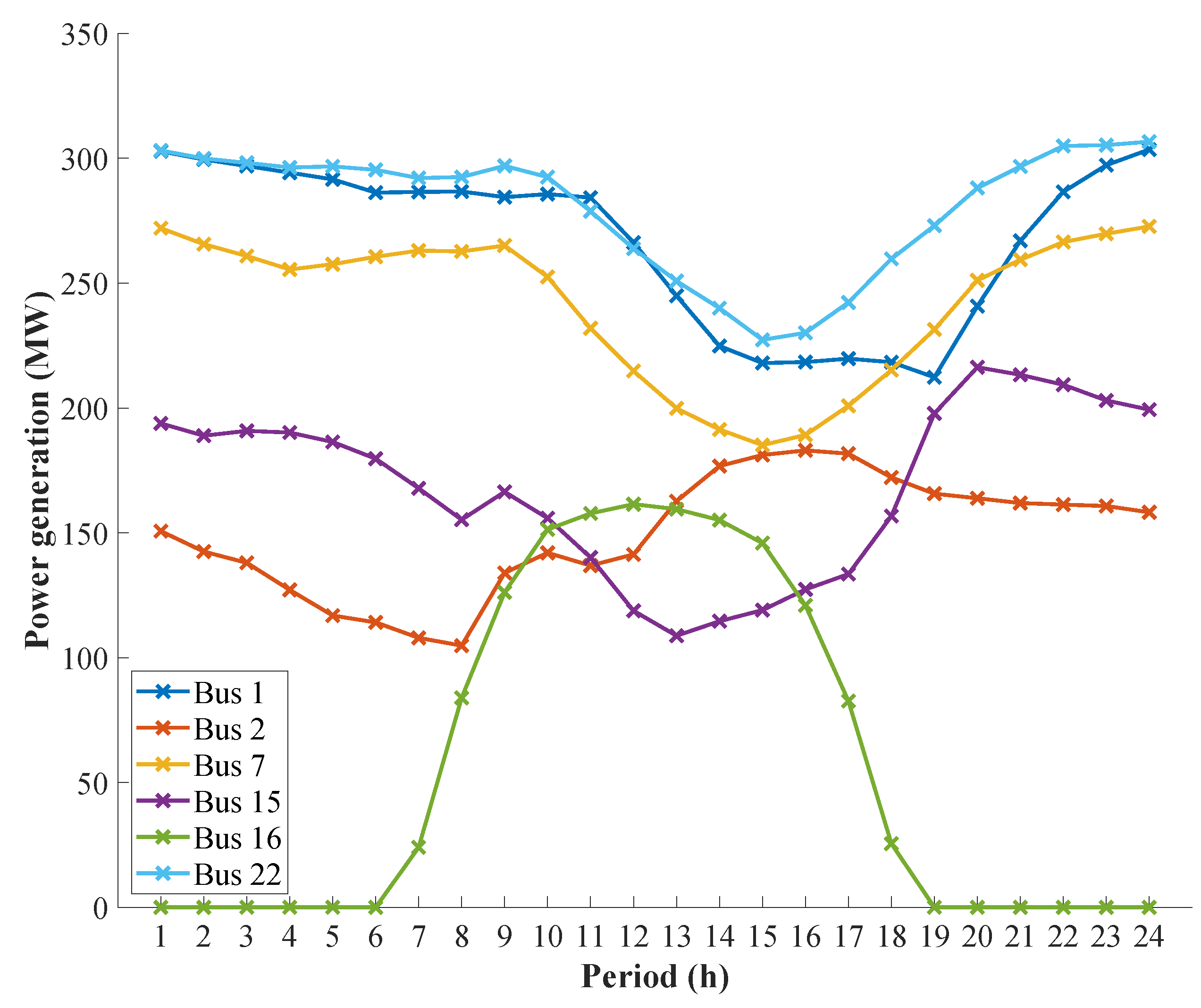
The data of the WPPs and PPPs are also based on real plants of the Brazilian northeast subsystem [27], and the wind farms are geographically distributed by The States to promote complementarity of the source. The wind and photovoltaic power generation values used to define P i , e x p W and P i , e x p P , respectively, are based on the average generation curves of the Brazilian system from August (highest annual average) of 2019, which can be seen in Figure 5.
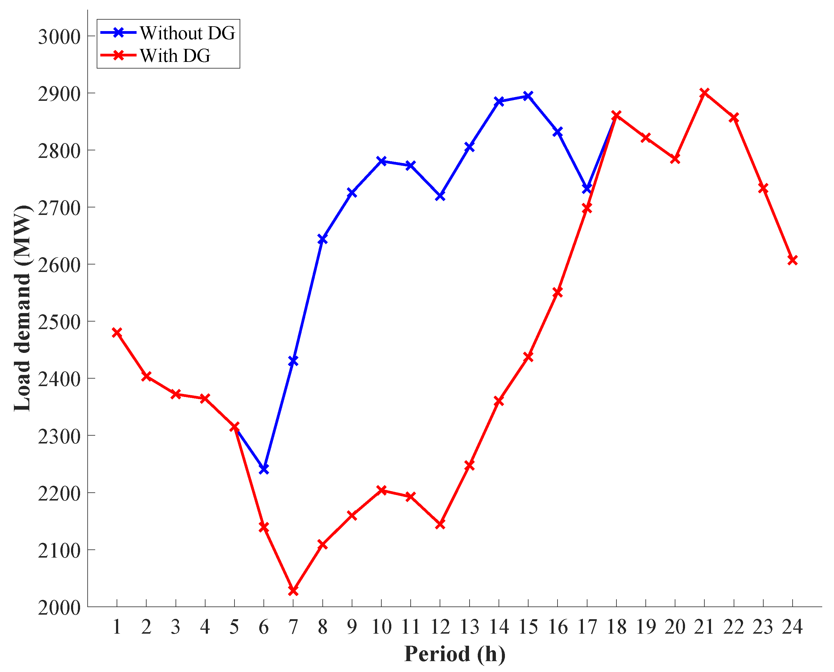
The load demand curve is shown in Figure 6, and it is obtained from historical data of the Brazilian Northeast subsystem from 21 August 2019 (highest average daily load demand). Therefore, it is possible to normalize the values and then multiply by 2900 MW to adapt with the modified IEEE 24-bus power system. However, for each hour, the load demand is distributed in percentages as the load bus in the power system.
To verify the effect of DG on the system in the coming years, a curve, based on data from photovoltaic generation in the northeast subsystem [26,27], was also normalized and multiplied by a factor that decreases 20% of the load demand curve from 6:00 a.m. to 6:00 p.m. This effect, caused by DG, is also shown in Figure 6.
Regarding transmission lines, this modified IEEE 24-bus power system has changed in the capacity of transmission, in which they are reduced by 15% from original values.
The following two cases are considered: in the first case, BESS was not used in the modified IEEE 24-bus power system; in the second case, BESS was connected to the bus that featured the WPC to observe the effect on results found in the first case.

3.2. DOS and Reduction of WPC

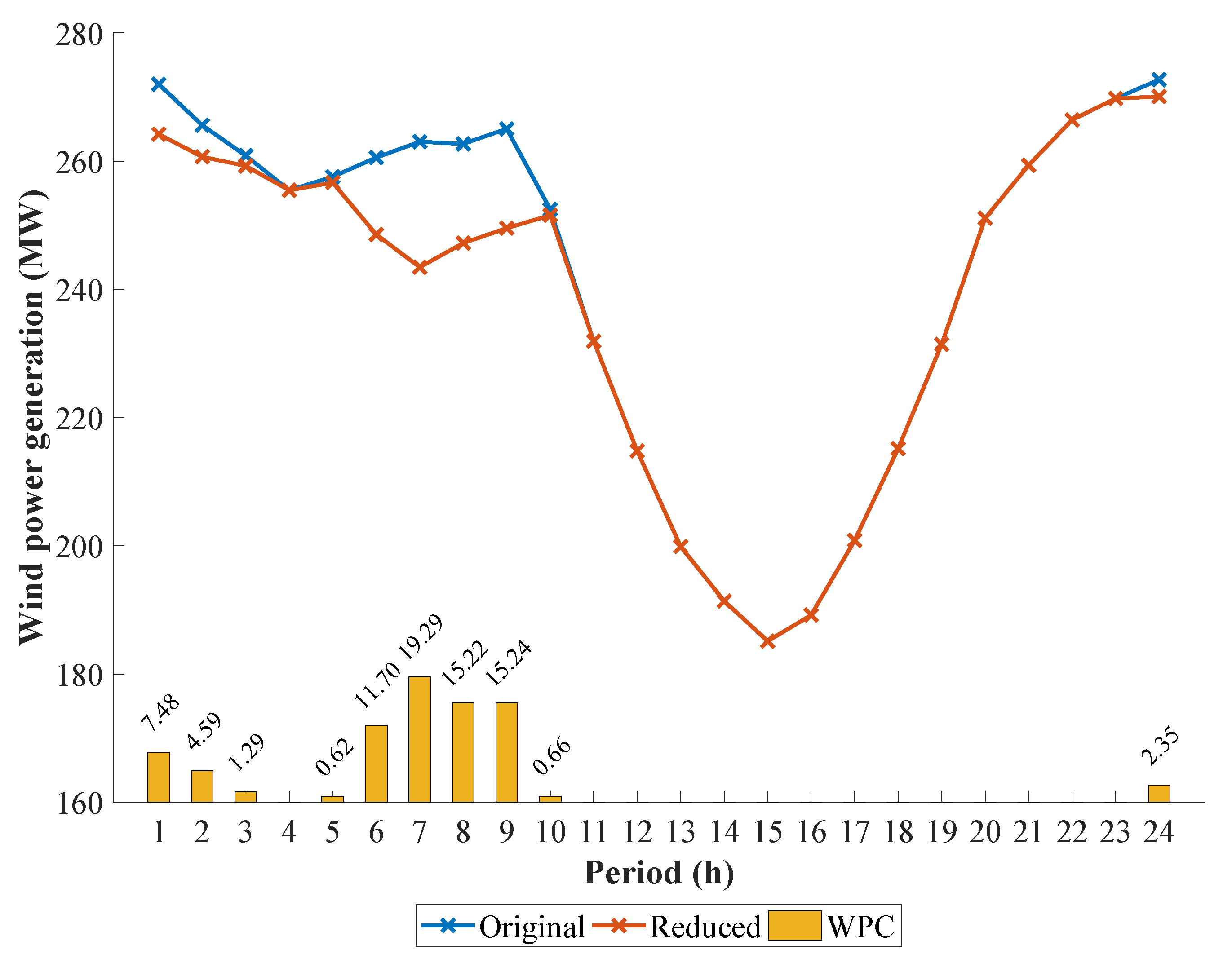
In Case 1, bus 7 of the modified IEEE 24-bus system presents the WPC, as can be seen in Figure 7. Ten out of 24 h there is a reduction in the production, totaling 78.44 MW at the end of the day. The highest curtailment period is from 6 a.m. to 9 a.m., when the net load demand, previously mentioned, is the lowest, and the wind and photovoltaic power generation are above their average (Table 4).
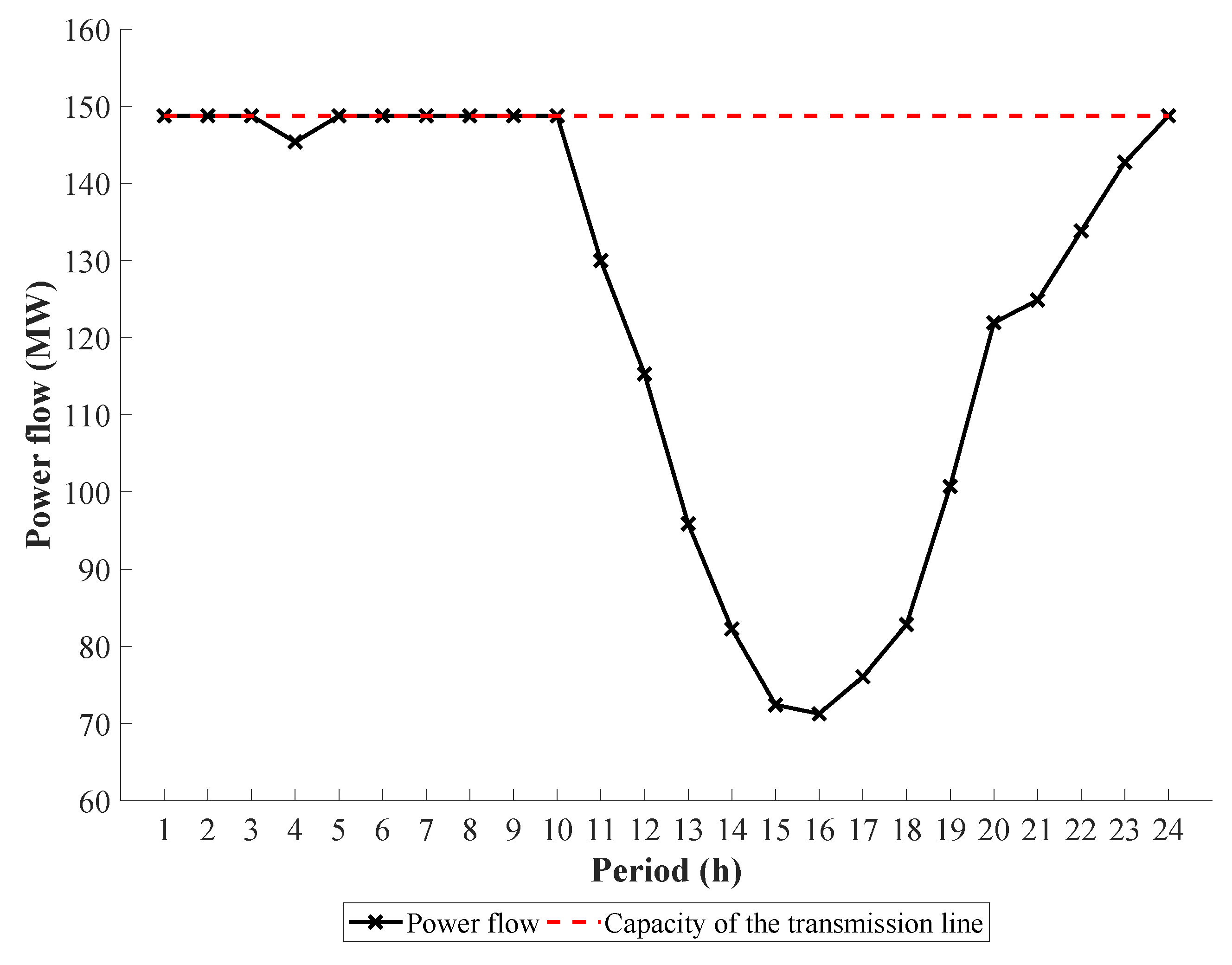
The WPC is found because transmission line 11, which connects buses 7 and 8, is congested, as can be seen in Figure 8 with the power flow solution. Then, in this case, it is necessary to reduce the power supply by the WWP of bus 7 not to exceed the safety limit of the transmission line. Thereby, the solution found by IPM is to use the cheapest source that will not compromise the problem constraints and will be able to supply the necessary load demand.
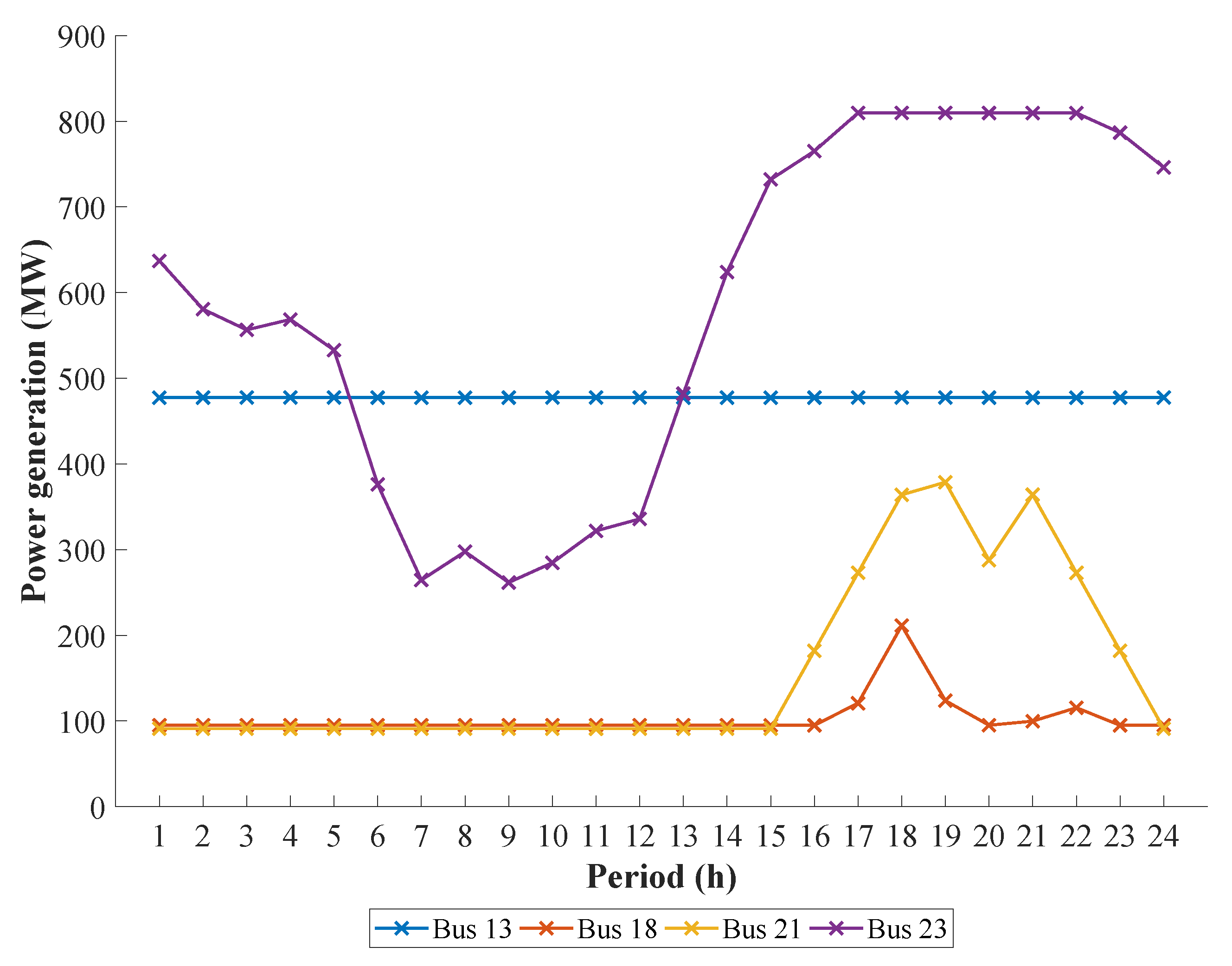
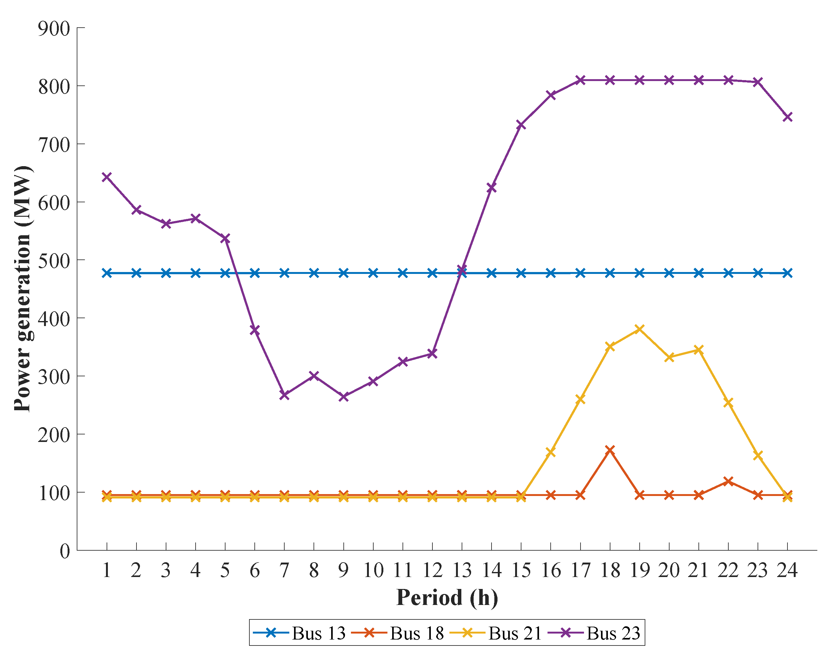
As can be seen in Figure 9, the source responsible to supply the load demand due to the WPC is the HPP from bus 23, since it is the only one among the conventional ones that have a dynamic performance in the first 13 h of the day. This same source manages to generate its total capacity in the second half of the day. This is explained by the fact that the same source is cheaper than TPPs, and the other HPP, on bus 18, has already had its maximum power generation all day long. According to the second half of the day in Figure 5, the renewable sources tend to have a lower generation average than the first half. For this reason, the TPPs must leave their minimum value and start to operate with higher values, respecting the ramp rate constraints. Therefore, the TPP from bus 21 can reach generation values close to its maximum (Figure 9). However, the TPP from bus 18, which is more expensive, can reach higher values than its minimum, but only in five moments of the day.
As the WPC occurs on the WPP located at bus 7, this location is chosen to place the BESS in Case 2. Furthermore, to be able to store an amount of energy equivalent to the WPC, it was decided to use higher storage capacity systems, which have already been implemented. Therefore, the BESS used has a Lithium Nickel Manganese Cobalt Oxides (Li-NMC) technology, and the parameters selected for this system can be seen in Table 5.
In Case 2, the WPC at bus 7 disappears, and the BESS performance for this to occur can be seen in Figure 10. In this study, it was considered that the initial state of storage is the minimum value. Consequently, the battery charges until 5:00 p.m., and it is at this time that the power supplied by PPP from bus 16 loses strength (Figure 5), the WPP at bus 7 is still close to its minimum value (also seen in Figure 5), and the load demand comes close to its peak value (Figure 6). From this time forth, BESS begins to discharge the stored power energy during the day until 8:00 p.m. Finally, without stored energy and with WPPs with values above the average (Table 4), the solution found by IPM is to store energy again up to 37% of BESS capacity and discharge it to the minimum value until the end of the day.
It can also be seen in Figure 11 that the power flow in Case 2 decays when BESS needs to store energy again at 8:00 p.m. In addition to that, unlike the result of Case 1 (Figure 8), the transmission line capacity is only reached at two times of the day, which leaves this part of the system looser.
Observing the power generation in Case 2 (Figure 12), there is a small increase in the power supplied by the HPPs. On average, bus 13 presented a reduction of 0.05 MWh, and bus 23 an increase of 3.67 MWh, as seen in Table 6. As for TPPs, they had a reduction in the energy generated. This fact can be explained since the objective of the problem is to minimize the operating cost of the sources. Therefore, BESS performs successfully in its function of storing cheaper energy and using it at times when the supply was previously made by the most expensive sources. Then, still observing Figure 12 and Table 6, there was a reduction, on average, in the power generation of TPPs, where bus 18 showed a reduction of 3.96 MWh, and bus 21 a reduction of 2.05 MWh.
In summary, even though the power generation of intermittent sources is present throughout the analyzed period, in a specific bus there was a waste of power that could be generated, causing an impact on the system operation. We noticed that the inclusion of BESS, with the appropriate characteristics, managed to solve this problem by reducing WPC. Although there is no significant change in the generation of conventional power sources, the decrease found in the results causes a reduction in operating costs, as will be seen below.

3.3. Operating Cost

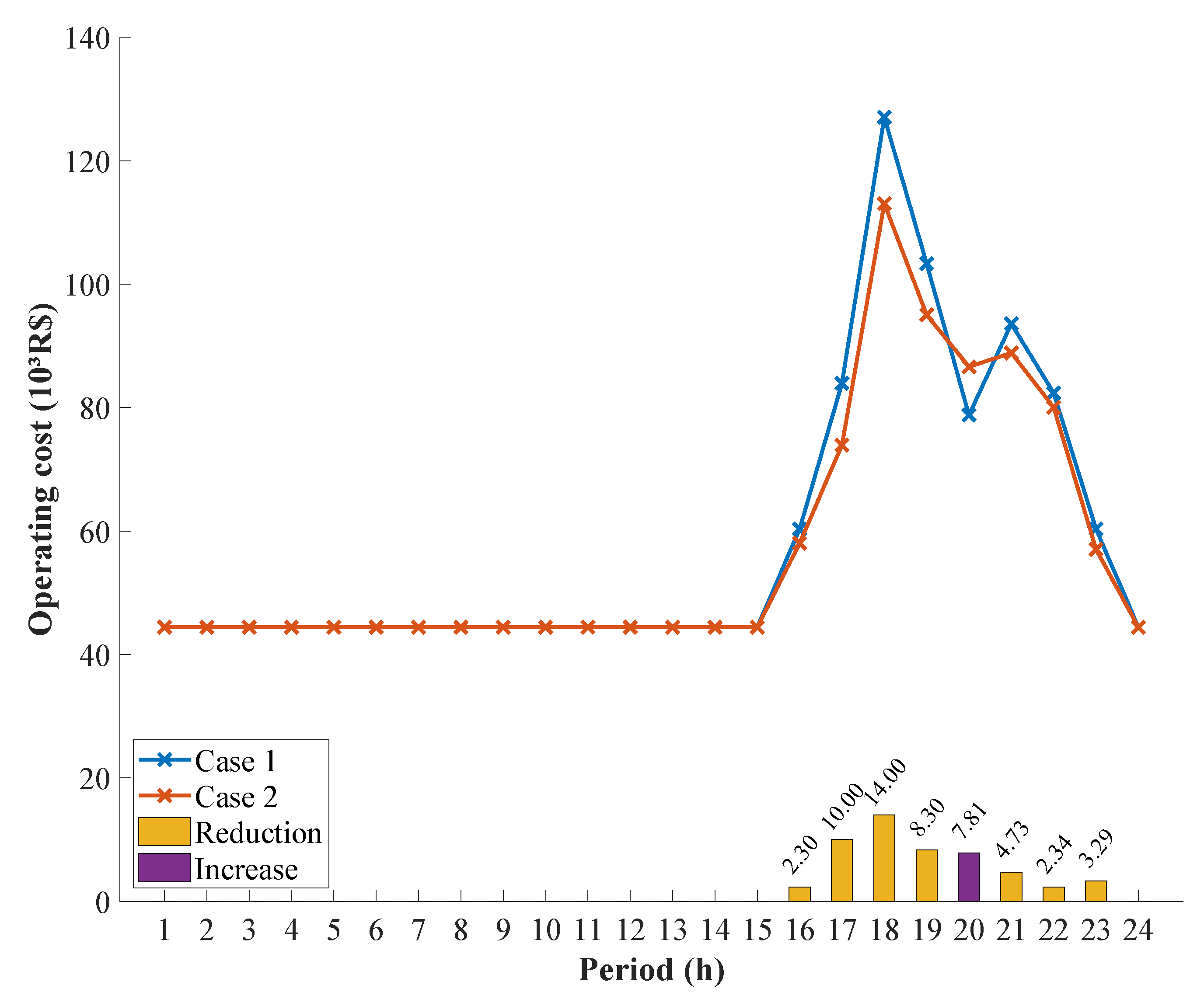
For most of the day, the operating cost in Case 2 is close to Case 1, as can be seen in Figure 13. However, during 7 h of the day, there is a reduction, and just in one hour, there is an increase. Analyzing the moments when the operating cost reduction occurs, the greatest variation is observed from 5:00 p.m. to 7:00 p.m. This can be explained since BESS discharges all the energy stored up to that moment during this interval. This causes a reduction in the generation of TPPs.
Continuing analyzing Figure 13 once more, 8:00 p.m. is the moment when there is an increase in the operating cost. The solution found requires that energy is stored up to 37% of the BESS capacity (Figure 10). Wind power solves this problem, and it is necessary to use the cheapest TPP (at bus 21) to supply the load demand. It can be observed that at this same time there is a drop in the power flow in the transmission line 11 from Case 2 (Figure 11), which indicates that the energy stored in BESS comes primarily from WPP on the same bus.
The reduction in the operating cost can also be seen through the analysis of the total value at the end of the day, which is reported in Table 7. It is possible to observe that the total operating cost was reduced by R$ 37,145.20 due to the use of BESS.

3.4. LMP

The LMP can be obtained for each of the buses in the system. However, due to the high number of buses, it was decided to represent this signal price through its average value. Therefore, the curves to be presented are the average LMP.
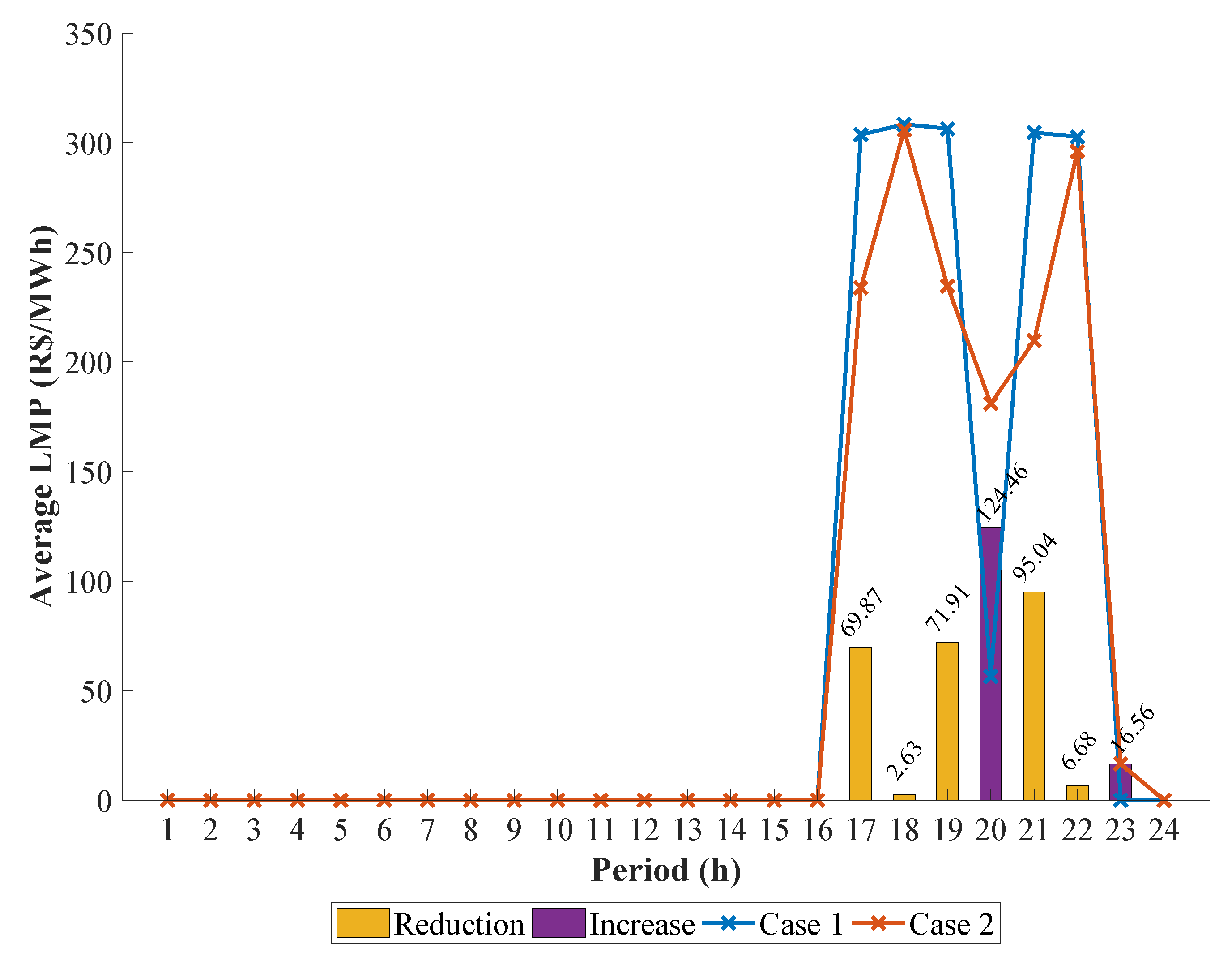
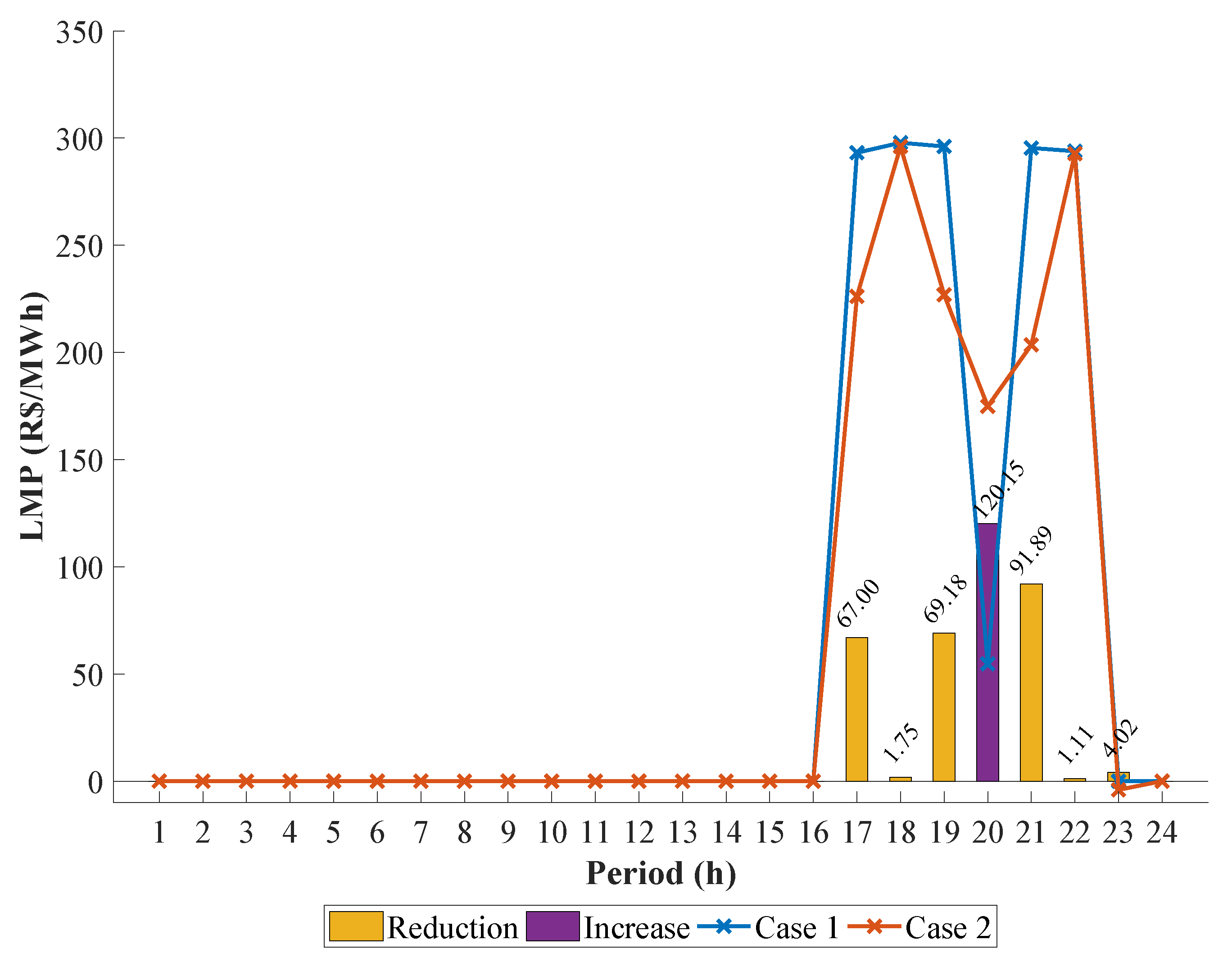
Analyzing the average LMP, it is possible to interpret the displacement of the energy stored during the day to reduce the pricing. In the first sixteen hours, the performance of the average LMP in Case 1 and Case 2 is equal to zero, as can be seen in Figure 14. The interpretation for this is that the system still offers a zero-cost dispatch distribution higher than the demand required at these times.
Analyzing the period from 4:00 p.m. to 11:00 p.m., in Figure 14, it is possible to understand the interference of charging and discharging of BESS in the average LMP. The energy that was previously wasted in Case 1, and now is stored by BESS in Case 2, is dispatched to reduce the five highest price points. In addition, it is observed that at 8:00 p.m. and 11:00 p.m. there was an increase in the average LMP value. However, this addition from one case to the other does not compromise the reduction of prices in the daily analysis.
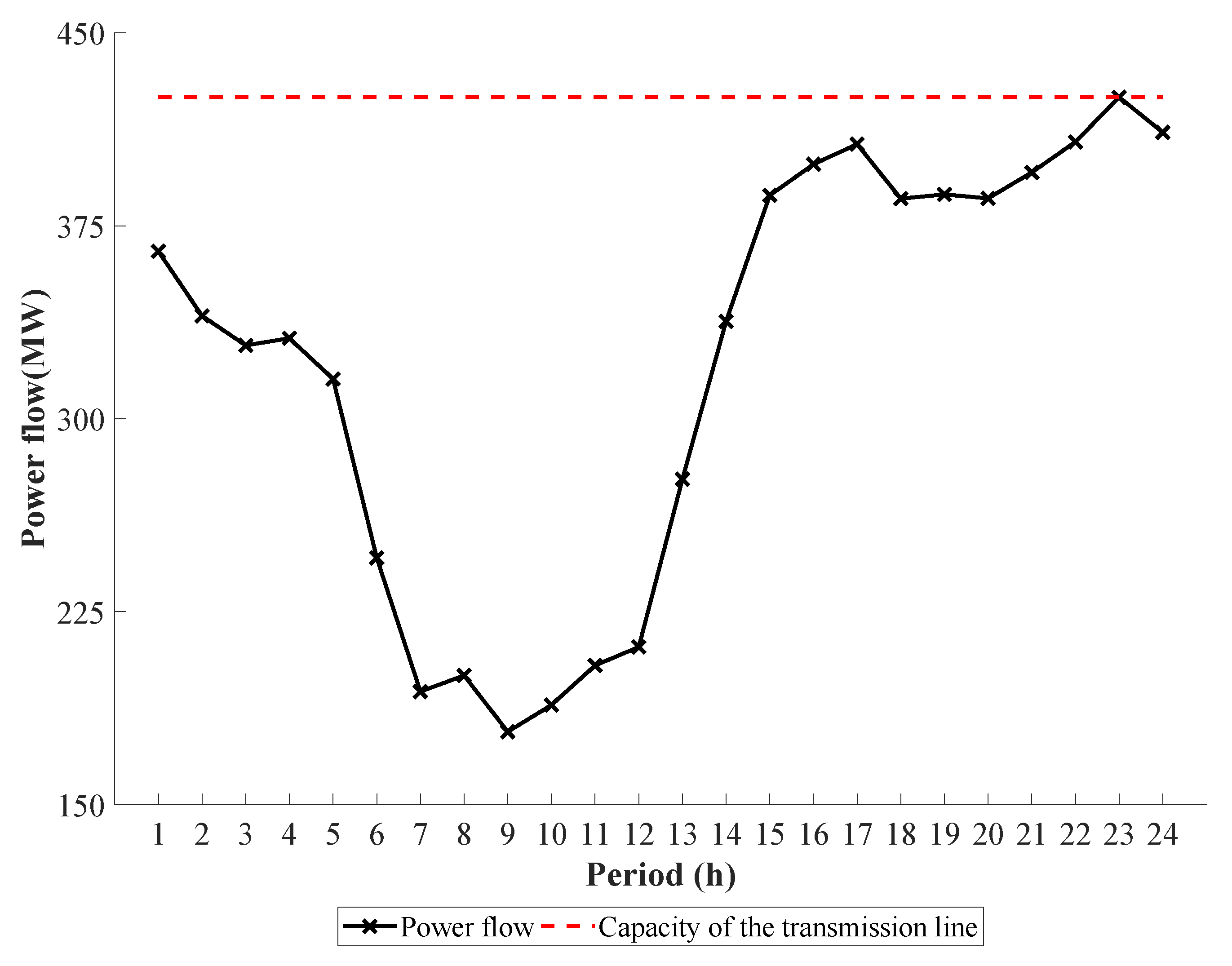
In the individual analysis of the LMP curves per bus, in Case 2, a negative value appears at 11:00 p.m. on bus 20, as shown in Figure 15. In this case, the energy previously dispatched from BESS makes TPP from bus 21 generates less energy power by TPP from bus 21, which is limited by its ramp rate constraint. To supply the demand at this time, an increase in the HPP from bus 23 was necessary, which caused the congestion of the transmission line 33 connecting buses 20 to 23 (Figure 16). The constraint at this time was significant making the cost paid for congestion and losses higher than the energy portion of the LMP.
The negative LMP for bus 20 (Figure 16) is the impact factor on the marginal cost of daily operation. Economically measured by technical aspects of plant operation and transmission line constraints, the negative value is an incentive sign for the consumption specifically at this bus. Hence, there is a financial benefit when the negative LMP occurs.

4. Conclusions

This paper considered the DOS in an HTWP power system with a high intake of wind power energy, which can be wasted due to the existing constraints in the optimization problem. WPP was modeled as a priority over other sources since its operating cost is equal to zero and promotes less environmental impact. In addition, WPPs may also control the power dispatch.
To reduce the WPC, it was proposed to use BESS on the same bus that the problem arises. In addition to being able to store the wasted energy, the storage system also promotes the benefit of relieving overloaded transmission lines. For this, it was observed that BESS fulfilled the role of shifting energy over time, as expected. Thus, the energy was stored during the period when there was less demand to be dispatched in moments of great load requests from the system.
The results for the modified IEEE 24-bus system showed that WPC can impact the operating costs. This is explained as other sources with a considerable cost must operate as a replacement for WPPs to supply the energy demand. It was observed that the use of BESS could promote a 2.65% reduction in operating costs in the analyzed case. As the analyzed system is a genuine reduction of the Brazilian power electric system, larger systems can generate even greater reductions.
In addition to reducing WPC and operating cost, the BESS used also impacted the average LMP, which signal prices were reduced to higher value times. This caused the appearance of a negative signal part in part of the system due to an overload in one of the transmission lines, indicating how susceptible the system can be.
We conclude that the modeling of WPP as a variable of the problem in cases in which there is a great intake of wind can promote better analysis of the WPC. This makes it possible to use storage energy systems to assist the elimination of WPC and other problems, such as the reduction of operating costs and daily signal prices.
We suggest for future work a further investigation of other energy storage technologies, the use of stochastic models for forecasting variables, and a study about the sensitivity of the signal prices with the presence of BESS in the power system. These additional analyses can promote an improvement in the results found here and open new study paths.

Author Contributions

Conceptualization, R.F.A.M., G.D.S., and R.R.B.d.A.; methodology, R.R.B.d.A.; software, R.F.A.M. and G.D.S.; validation, R.R.B.d.A.; formal analysis, R.R.B.d.A.; investigation, R.F.A.M. and G.D.S.; resources, R.R.B.d.A.; data curation, R.F.A.M. and G.D.S.; writing—original draft preparation, R.F.A.M.; writing—review and editing, R.F.A.M., G.D.S., and R.R.B.d.A.; visualization, R.F.A.M.; supervision, R.R.B.d.A.; project administration, R.R.B.d.A.; funding acquisition, R.R.B.d.A. All authors have read and agreed to the published version of the manuscript.

Funding

This work was supported by Brazilian Coordination for the Improvement of Higher Education Personnel (CAPES) and Federal University of Pernambuco (UFPE) through the PROPG 03/2020 announcement.

Institutional Review Board Statement

Not applicable.

Informed Consent Statement

Not applicable.

Data Availability Statement

We applied our proposed approach to the case study inspired by the IEEE 24-bus test system data. We used the adapted version of the IEEE 24-bus test system data, which the data can be found in this link https://drive.google.com/drive/folders/1TB32ywqKnwdsPEhifn6KY3XQ2OVSuxIf?usp=sharing [26,27,42,43] (accessed on 16 February 2020).

Conflicts of Interest

The authors declare no conflict of interest.

Abbreviations

The following abbreviations are used in this manuscript:
BESSBattery Energy Storage System
DCOPFDC Optimal Power Flow
DGDistributed Generation
DOSDaily Operation Scheduling
FNDFictitious Nodal Demand
HPPHydroelectric Power Plant
HTWPHydro-Thermal-Wind-Photovoltaic
IPMInterior Point Method
Li-NMCLithium Nickel Manganese Cobalt Oxides
LMPLocational Marginal Pricing
MDFMarginal Delivery Factor
MLFMarginal Loss Factor
PPPPhotovoltaic Power Plant
PTDFPower Transfer Distribution Factors
SOCState of Charge
TPPThermoelectric Power Plants
WPCWind Power Curtailment
WPPWind Power Plant

References

  1. Calif, R.; Schmitt, F.; Duran, O.M. −5/3 Kolmogorov turbulent behavior and Intermittent Sustainable Energies. In Sustainable Energy; Zobaa, A., Aleem, S.A., Afifi, S.N., Eds.; Intech: Rijeka, Croatia, 2016. [Google Scholar] [CrossRef]
  2. de Jong, P.; Kiperstok, A.; Sanchez, A.S.; Dargaville, R.; Torres, E. Integrating large scale wind power into the electricity grid in the Northeast of Brazil. Energy 2016, 100, 401–415. [Google Scholar] [CrossRef]
  3. de Jong, P.; Dargaville, R.; Silver, J.; Utembe, S.; Kiperstok, A.; Torres, E. Forecasting high proportions of wind energy supplying the Brazilian Northeast electricity grid. Energy 2017, 195, 538–555. [Google Scholar] [CrossRef]
  4. Boicea, V.A. Energy storage technologies: The past and the present. Proc. IEEE 2014, 11, 1777–1794. [Google Scholar] [CrossRef]
  5. Zhao, H.; Wu, Q.; Hu, S.; Xu, H.; Rasmussen, C.N. Review of energy storage system for wind power integration support. Appl. Energy 2015, 137, 545–553. [Google Scholar] [CrossRef]
  6. Farhadi, M.; Mohammed, O. Energy storage technologies for high-power applications. IEEE Trans. Ind. Appl. 2016, 52, 1953–1961. [Google Scholar] [CrossRef]
  7. Hu, X.; Zou, C.; Zhang, C.; Li, Y. Technological developments in batteries: A survey of principal roles, types, and management needs. IEEE Power Energy Mag. 2017, 15, 20–31. [Google Scholar] [CrossRef]
  8. Finardi, E.C.; Scuzziato, M.R. Hydro unit commitment and loading problem for day-ahead operation planning problem. Int. J. Electr. Power 2013, 44, 7–16. [Google Scholar] [CrossRef]
  9. Pereira, M.G.; Camacho, C.F.; Freitas, M.A.V.; da Silva, N.F. The renewable energy market in Brazil: Current status and potential. Renew. Sustain. Energy Rev. 2012, 16, 3786–3802. [Google Scholar] [CrossRef]
  10. Nogueira, L.A.H.; Cardoso, R.B.; Cavalcanti, C.Z.B.; Leonelli, P.A. Evaluation of the energy impacts of the energy efficiency law in Brazil. Energy Sustain. Dev. 2015, 24, 58–69. [Google Scholar] [CrossRef]
  11. Guerra, J.B.S.O.A.; Dutra, L.; Schwinden, N.B.C.; de Andrade, S.F. Future scenarios and trends in energy generation in Brazil: Supply and demand and mitigation forecasts. J. Clean. Prod. 2015, 103, 197–210. [Google Scholar]
  12. Dranka, E.G.; Ferreira, P. Planning for a renewable future in the Brazilian power system. Energy 2018, 164, 496–511. [Google Scholar] [CrossRef]
  13. Fu, Y.; Li, Z. Different Models and Properties on LMP Calculations. In Proceedings of the IEEE Power Engineering Society General Meeting, Montreal, QC, Canada, 18–22 June 2006; pp. 1–11. [Google Scholar]
  14. Ela, E.; Edelson, D. Participation of wind power in LMP-based energy markets. IEEE Trans. Sustain. Energy 2012, 3, 777–783. [Google Scholar] [CrossRef]
  15. Zhao, Z.; Wu, L. Impacts of high penetration wind generation and demand response on LMPs in day-ahead market. IEEE Trans. Smart Grid 2014, 5, 220–229. [Google Scholar] [CrossRef]
  16. Yan, X.; Gu, C.; Li, F.; Wang, Z. LMP-based pricing for energy storage in local market to facilitate PV penetration. IEEE Trans. Power Syst. 2018, 33, 3373–3382. [Google Scholar] [CrossRef]
  17. Zhong, J. Power System Economic and Market Operations; CRC Press: Boca Raton, FL, USA, 2018; pp. 136–167. [Google Scholar]
  18. Cotia, B.P.; Borges, C.L.T.; Diniz, A.L. Optimization of wind power generation to minimize operation costs in the daily scheduling of hydrothermal systems. Int. J. Electr. Power 2019, 113, 539–548. [Google Scholar] [CrossRef]
  19. Xiong, W.; Wang, Y.; Mathiesen, B.V.; Zhang, X. Case study of the constraints and potential contributions regarding wind curtailment in Northeast China. Energy 2016, 110, 55–64. [Google Scholar] [CrossRef]
  20. Qi, Y.; Zhang, N.; Huang, Y.; Wang, Y.; Wang, W.; Liu, C. Wind power curtailment sequence characteristic analysis. J. Eng. 2017, 2017, 1662–1665. [Google Scholar] [CrossRef]
  21. Li, H.; Wang, X.; Li, F.; Wang, Y.; Yu, X. A robust day-ahead electricity market clearing model considering wind power penetration. Energies 2018, 11, 1772. [Google Scholar] [CrossRef] [Green Version]
  22. Li, F.; Bo, R. DCOPF-based LMP simulation: Algorithm, comparison with ACOPF, and sensitivity. IEEE Trans. Power Syst. 2007, 22, 1475–1485. [Google Scholar] [CrossRef]
  23. Li, F.; Bo, R. Small Test Systems for Power System Economic Studies. In Proceedings of the IEEE Power Engineering Society General Meeting, Minneapolis, MN, USA, 25–29 July 2010; pp. 1–4. [Google Scholar]
  24. Li, F. Fully reference-independent LMP decomposition using reference independent loss factors. Electr. Pow. Syst. Res. 2011, 81, 1995–2004. [Google Scholar] [CrossRef]
  25. Boonchuay, C.; Tomsovic, K.; Li, F.; Ongsakul, W. Robust Optimization-Based DC Optimal Power Flow for Managing Wind Generation Uncertainty. In Proceedings of the AIP Conference, Las Vegas, NV, USA, 6–8 August 2012; pp. 31–35. [Google Scholar]
  26. Energy Research Office. Available online: https://www.epe.gov.br/pt/publicacoes-dados-abertos/publicacoes/plano-decenal-de-expansao-de-energia-2030 (accessed on 29 December 2020).
  27. Brazilian National System Operator. Available online: http://www.ons.org.br/Paginas/resultados-da-operacao/historico-da-operacao/ (accessed on 29 December 2020).
  28. de Lima, F.J.L.; Martins, F.R.; Costa, R.S.; Gonçalves, A.R.; dos Santos, A.P.P.; Pereira, E.B. The seasonal variability and trends for the surface solar irradiation in northeastern region of Brazil. Sustain. Energy Technol. Assess. 2019, 35, 335–346. [Google Scholar]
  29. dos Santos, S.P.; de Aquino, R.R.B.; Neto, O.N. A proposal for analysis of operating reserve requirements considering renewable sources on supergrids. Electr. Eng. 2020, 1–12. [Google Scholar] [CrossRef]
  30. Wood, A.J.; Wollenberg, B.F.; Sheble, G.B. Power Generation, Operation, and Control; John Wiley & Sons: New York, NY, USA, 2012; pp. 18–19. [Google Scholar]
  31. Hozouri, M.A.; Abbaspour, A.; Fotuhi-Firuzabad, M.; Moeini-Aghtaie, M. On the use of pumped storage for wind energy maximization in transmission-constrained power systems. IEEE Trans. Power Syst. 2014, 30, 1017–1025. [Google Scholar] [CrossRef]
  32. Zheng, L.; Hu, W.; Lu, Q.; Min, Y. Optimal energy storage system allocation and operation for improving wind power penetration. IET Gener. Transm. Dis. 2015, 9, 2672–2678. [Google Scholar] [CrossRef] [Green Version]
  33. Imani, M.H.; Niknejad, P.; Barzegaran, M.R. Implementing time-of-use demand response program in microgrid considering energy storage unit participation and different capacities of installed wind power. Electr. Power Syst. Res. 2019, 175, 1–10. [Google Scholar]
  34. Roques, F.; Hiroux, C.; Saguan, M. Optimal wind power deployment in Europe: A portfolio approach. Energy Policy 2010, 38, 3245–3256. [Google Scholar] [CrossRef] [Green Version]
  35. Dowds, J.; Hines, P.; Ryan, T.; Buchanan, W.; Kirby, E.; Apt, J.; Jaramillo, P. A review of large-scale wind integration studies. Renew. Sustain. Energy Rev. 2015, 49, 768–794. [Google Scholar] [CrossRef]
  36. Böhme, G.S.; Fadigas, E.A.; Soares, D.; Gimenes, A.L.V.; Macedo, B.C. Wind speed variability and portfolio effect: A case study in the Brazilian market. Energy 2020, 207, 1–20. [Google Scholar] [CrossRef]
  37. Yin, Y.; Liu, T.; He, C. Day-ahead stochastic coordinated scheduling for thermal-hydro-wind-photovoltaic systems. Energy 2019, 187, 1–13. [Google Scholar] [CrossRef]
  38. Lueken, R.; Apt, J. The effects of bulk electricity storage on the PJM market. Energy Syst. 2014, 5, 677–704. [Google Scholar] [CrossRef]
  39. Fang, X.; Li, F.; Wei, Y.; Cui, H. Strategic scheduling of energy storage for load serving entities in locational marginal pricing market. IET Gener. Transm. Dis. 2016, 10, 1258–1267. [Google Scholar] [CrossRef]
  40. Zhang, Y.; Rahbari-Asr, N.; Duan, J.; Chow, M. Day-ahead smart grid cooperative distributed energy scheduling with renewable and storage integration. IEEE Trans. Sustain. Energy 2016, 7, 1739–1748. [Google Scholar] [CrossRef]
  41. Yan, X.; Gu, C.; Wyman-Pain, H.; Li, F. Capacity share optimization for multiservice energy storage management under portfolio theory. IEEE Trans. Ind. Electron. 2019, 66, 1598–1607. [Google Scholar] [CrossRef]
  42. Grigg, C.; Wong, P.; Albrecht, P.; Allan, R.; Bhavaraju, M.; Billinton, R.; Chen, Q.; Fong, C.; Haddad, S.; Kuruganty, S.; et al. The IEEE Reliability Test System-1996. A report prepared by the Reliability Test System Task Force of the Application of Probability Methods Subcommittee. IEEE Trans. Power Syst. 1999, 14, 1010–1020. [Google Scholar] [CrossRef]
  43. Platte River Power Authority. Battery Energy Storage Technology Assessment; Platte River Power Authority: Fort Collins, CO, USA, 2017. [Google Scholar]

Short Biography of Authors

Energies 14 01441 i001Roberto Felipe Andrade Menezes was born in Aracaju, Brazil, in 1988. He received the B.S. and M.Sc. degrees in Electrical Engineering from the Federal University of Sergipe, Aracaju, SE, Brazil, in 2013 and 2017, respectively. He is currently working toward a Ph.D. degree at the Federal University of Pernambuco, Recife, PE, Brazil. His main research interests are the integration of renewable energy resources, battery energy storage systems, smart grids, optimization, and electricity markets.
Energies 14 01441 i002Guilherme Delgado Soriano was born in Recife, Brazil, in 1989. He received the B.S. and M.Sc. degrees in Electrical Power Engineering from the Federal University of Pernambuco, Recife, PE, Brazil, in 2013 and 2016, respectively. He is currently working toward a Ph.D. degree at the Federal University of Pernambuco, Recife, PE, Brazil. His major interests are in the area of renewable energy, power system planning, and optimal power flow.
Energies 14 01441 i003Ronaldo Ribeiro Barbosa de Aquino was Born in Recife, Brazil, in 1962. He received the B.S. and M.Sc. degrees in Electrical Engineering from the Federal University of Pernambuco, Recife, PE, Brazil, in 1983 and 1995, respectively, and the D.Sc. degree from the Federal University of Paraiba, Brazil, in 2001. Since 1995 he has been with the Federal University of Pernambuco. He is currently an Associate Professor IV and was Head of the Department of Electrical Engineering at the Federal University of Pernambuco in the periods Feb/2001–Feb/2005 and Oct/2014–Oct/2018. His research interests are with applications of artificial intelligence tools such as artificial neural networks, adaptive neuro-fuzzy inference systems, echo state network to power systems, and control systems. The applications are related to the electrical load and wind forecasting, economic load dispatch, insulators diagnosis, and industrial control systems focused on energetic efficiency.
Figure 1. Comparison among average affluent natural energy, average wind power generation, and average photovoltaic power generation in 2019. Data source: [27].
Energies 14 01441 g001
Figure 2. Average hourly capacity factor of wind power plants (WPPs) in states of Bahia (inland) and Rio Grande do Norte (coast), and daily profile of average load demand in the Brazilian northeast subsystem in 2019. Data source: [27].
Energies 14 01441 g002
Figure 3. DC optimal power flow (DCOPF) iterative method considering system losses.
Energies 14 01441 g003
Figure 4. Diagram of modified IEEE 24-bus power system.
Energies 14 01441 g004
Figure 5. Wind and photovoltaic power generation values. Data source: [27].
Energies 14 01441 g005
Figure 6. Load demand curve along the day with and without Distributed Generation (DG). Data source: [26,27].
Energies 14 01441 g006
Figure 7. Wind power generation and wind power curtailment (WPC) of bus 7 in Case 1.
Energies 14 01441 g007
Figure 8. Power flow at transmission line 11 in Case 1.
Energies 14 01441 g008
Figure 9. Hydro and thermal power generation values in Case 1.
Energies 14 01441 g009
Figure 10. Behavior of BESS at bus 7 in Case 2.
Energies 14 01441 g010
Figure 11. Power flow at transmission line 11 in Case 2.
Energies 14 01441 g011
Figure 12. Hydro and thermal power generation values in Case 2.
Energies 14 01441 g012
Figure 13. Operating costs in Case 1 and Case 2.
Energies 14 01441 g013
Figure 14. Average Locational Marginal Pricing (LMP) in Case 1 and Case 2.
Energies 14 01441 g014
Figure 15. LMP in Case 1 and Case 2 at bus 20.
Energies 14 01441 g015
Figure 16. Power flow at transmission line 33 in Case 2.
Energies 14 01441 g016
Table 1. Installed power capacity of the original and modified IEEE 24-bus system. Data source: [27,42].
BusInstalled Power Capacity of the
Original IEEE 24-Bus System (MW)
Installed Power Capacity of the
Modified IEEE 24-Bus System (MW)
1192 (TPP)188 (WPP)
2192 (TPP)167 (WPP)
7300 (TPP)257 (WPP)
13591 (TPP)462 (HPP)
15215(TPP)200 (WPP)
16155 (TPP)145 (PPP)
18400 (TPP)381 (TPP)
21400 (TPP)365 (TPP)
22300 (TPP)291 (WPP)
23660 (TPP)794.2 (HPP)
Table 2. Final installed power capacity of the modified IEEE 24-bus.
BusInstalled Power Capacity of the
Modified IEEE 24-Bus System (MW)
Location (Brazilian State)
1203.5 (WPP)Piauí
2182.5 (WPP)Ceará
7272.5 (WPP)Bahia
13477.5 (HPP)Bahia
15215.5 (WPP)Rio Grande do Norte
16160.5 (PPP)Bahia
18396.5 (TPP)Pernambuco
21380.5 (TPP)Ceará
22306.5 (WPP)Bahia
23809.7 (HPP)Bahia
Table 3. Characteristics of the Thermoelectric Power Plant (TPP) and the Hydroelectric Power Plant (HPP). Data source: [27].
BusSource P i , min (MW) P i , max (MW) R i (MW) c i (R$/MWh)
13HPP115.5477.53620
18TPP95396.595300
21TPP91380.591174.84
23HPP198.5809.7611.20
Table 4. Summary of wind and photovoltaic power generation values. Data source: [27].
BusMinimum (MW)Maximum (MW)Average (MW)
1212.29303.5267.36
2104.82183.02149.39
7185.12270.36238.17
15108.77216.3168.03
160161.4758.09
22227.28306.66280.46
Table 5. Parameters of battery energy storage system (BESS) at bus 7 in Case 2. Data source: [43].
Parameter E i , max P i , max C P i , max D γ i η i S i , min S i , max
Value150 MWh50 MW50 MW2%95%10%90%
Table 6. Variation of the hydro and thermal power generation between Case 1 and Case 2, on average.
Bus13182123
Variation (MWh)−0.05+3.67−3.96−2.05
Table 7. Operating cost variation between Case 1 and Case 2.
Case 1Case 2Variation (R$)
R$1,400,237.52R$1,363,092.32−37,145.20
Publisher’s Note: MDPI stays neutral with regard to jurisdictional claims in published maps and institutional affiliations.