Article

Analysis and Simulation of an Absorption Cooling System Using a Latent Heat Storage Tank and a Tempering Valve

1
Centro de Investigación en Ingeniería y Ciencias Aplicadas, Universidad Autónoma del Estado de Morelos, Av. Universidad 1001, Cuernavaca 62209, Morelos, Mexico
2
Facultad de Ingeniería, Universidad Autónoma de Baja California, Blvd. Benito Juárez y Calle de la Normal s/n, Insurgentes Este, Mexicali 21280, Baja California, Mexico
*
Author to whom correspondence should be addressed.
Energies 2021, 14(5), 1376; https://doi.org/10.3390/en14051376
Submission received: 6 February 2021 / Revised: 26 February 2021 / Accepted: 27 February 2021 / Published: 3 March 2021

Abstract

:
The energy consumption for space cooling is growing faster than for any other end-use in buildings, more than tripling between 1990 and 2016. Energy efficiency is an important topic in the drive to reduce the consumption of electricity, particularly in air conditioning. This paper presents a simulation of an absorption cooling system with a parabolic trough collector under dynamic conditions using TRaNsient SYstem Simulation (TRNSYS) software. The thermal analysis seeks to evaluate a storage tank at three different configurations: (1) sensible heat, (2) latent heat, and (3) latent heat incorporating a tempering valve. The latent heat storage tank is a rectangular heat exchanger using MgCl2·6H2O as the phase change material, programmed in EES software; in addition, water and synthetic organic fluid were analyzed as heating fluids. The process was analyzed while varying the solar collector area from 20 to 40 m2 and the storage tank volume from 0.25 to 0.75 m3. The results showed that the solar collector of configuration 1 is unable to satisfy the energy demand. Configuration 2 can satisfy the demand with water and a storage tank volume above 0.50 m3 and 30 m2, while configuration 3 can satisfy the demand above 0.50 m3 and 20 m2 with water.

1. Introduction

The use of air conditioners and electric fans in buildings is responsible for nearly 20% of the total electricity consumption around the world. This consumption is increasing due to demographic growth and the fact that more people naturally wish to live under comfortable temperature [1]. Renewable energy initiatives have been implemented in many countries to reduce greenhouse emissions. However, the problem associated with some renewable energies such as solar and wind is that they are only available for a finite period of time [2].
Energy storage has become an important complement to renewable energy technology systems. Thermal energy storage is a technology that stocks thermal energy that can be used at a later date for heating or cooling applications [3]. Absorption chillers are an interesting technology used to acclimatize spaces; however, they are not able to economically compete with conventional cooling (vapor compression). Therefore, moving forward, the research and development (R&D) projects must optimize the cycle, minimize parasitic losses, improve the auxiliary system, numerous controls and operation aspects, and improve the design and integration of thermal storage [4].
Sensible heat is commonly used in storage tanks for absorption systems when radiation is not available. This is a significant drawback because they require large spaces and heavy tanks. Phase change materials (PCMs) have recently been used in absorption cooling systems to reduce the size of the tanks because it can save more thermal energy in smaller spaces because of the latent heat. Fan et al. [5] presented a numerical study of a shell-and-tube heat exchanger as a latent heat storage tank (LHST) using hydroquinone, combined with a solar-driven H2O/LiBr double-effect absorption system. The phase change was numerically solved using the enthalpy method. The results indicated that natural convection cannot be neglected in the solidification process; in addition, the peak cooling demand (100 kW) was satisfied by only using 12.55 m3 of LHST and parabolic trough collectors for a 2400 m2 office building.
Pintaldi et al. [6] analyzed the benefits of using sensible (water and oil) and latent (KNO3/NaNO3 and AlSn) storage systems coupled with a triple effect chiller operation. The thermal energy is provided through the parabolic trough collector at 200 °C using a vertical shell and tube heat exchanger as storage tank. The results showed that the latent heat storage systems obtained high storage efficiencies compared to sensible heat storage systems since the reduced storage sizes yielded lower heat losses. Alternatively, solar collectors had a higher yield using a sensible heat storage medium.
Zhou et al. [7] numerically and experimentally analyzed a single/double hybrid effect (SDHE) absorption system composed of linear Fresnel reflector solar collector arrays. A shell and tube heat exchanger was used as a thermal storage tank to store molten salt. The coefficient of operation was varied from 0.73 to 1.09 when the operation mode of the SDHE switched from single effect to double. Meanwhile, the inlet temperature of hot water increased from 141.5 to 155.4 °C. The optimized region of the solar collector area and thermal storage capacity were within the ranges of 900–1100 m2 and 5.0–8.5 m3, respectively.
At present, sensible heat storage tanks are usually used in absorption chillers due to the relatively low cost, easy design, and high heat capacity of water. PCMs have not yet been widely adopted in designs in this field; however, it is a promising candidate to reduce the size of the storage tank material for solar absorption cooling systems [4]. This paper presents a thermal analysis of a single-stage LiBr-H2O absorption chiller heated by a parabolic trough collector (PTC) using three configurations in order to evaluate the efficiency of the system: (a) sensible heat (SHST), (b) latent heat (LHST) storage tank and (c) LHST with a tempering valve. The LHST is modeled in two dimensions and transition conditions. In addition to water, synthetic organic fluid was analyzed as a heating fluid.

2. Latent Heat Storage Tank Model Development

A rectangular heat exchanger was chosen as the LHST. It consisted of three flat containers that included a phase change material (PCM) and four channels in which heating fluid (HF) flows were used to extract or supply energy (see Figure 1). The following assumptions were made in the development of the mathematical model:
  • the PCM is homogeneous and isotropic;
  • the thermophysical properties of the PCM are independent of temperature;
  • the phase change of the PCM is assumed to be isothermal;
  • the thermal resistance of the metal wall of the plates is insignificant;
  • the temperatures of the input and output heating fluid are considered well mixed.
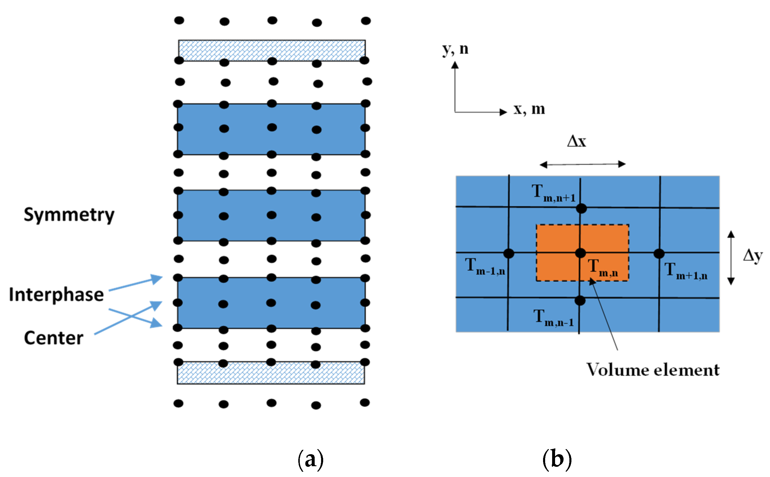
The mathematical model was solved by a finite difference scheme; each node was discretized in time in two dimensions, as shown in Figure 2a. Symmetry was considered to simplify the simulation and reduce the number of nodes by half. The m and n subscripts are the node counts in the x and y directions (Figure 2b).

2.1. Governing Equations

The following equations are the governing conservation equations expressed in the finite difference formulation in transient conditions, solved using the implicit method:
Heating fluid
m HF Cp HF ( T m 1 , n i + 1 T m , n i + 1 ) + m HF Cp HF ( T m + 1 ,   n i + 1 T m , n i + 1 ) + h HF i + 1 Δ A y ( T m , n + 1 i + 1 T m , n i + 1 ) + h HF i + 1 Δ A y ( T m , n 1 i + 1 T m , n i + 1 ) = ρ HF Cp HF Δ V ( T m , n i + 1 T m , n i ) Δ t
where m, T, Cp, h and ρ are the flow rate (kg/s), temperature (°C), heat capacity (kJ/kg °C), convection heat transfer coefficient of the heating fluid (kW/m2 °C) and density (kg/m3), respectively; ΔAy and ΔV are the area in the y direction and volume element, respectively. T m , n i and T m , n i + 1 are the temperatures of node m, n at times ti = iΔt and ti+1 = (i+1)Δt, respectively. Δt is the step time.
PCM container
Center. The energy balance is carried out in the center of the PCM container (see Figure 2a) as follows:
k PCM Δ A x ( T m 1 , n i + 1 T m , n i + 1 ) Δ x +   k PCM Δ A x ( T m + 1 , n i + 1 T m , n i + 1 ) Δ x +   k PCM Δ A y ( T m , n + 1 i + 1 T m , n i + 1 ) Δ y +   k PCM Δ A y ( T m , n 1 i + 1 T m , n i + 1 ) Δ y = ρ PCM Cp PCM Δ V ( T m , n i + 1 T m , n i ) Δ t ,
where Δx and Δy are the nodal points spaced throughout the rectangular mesh (see Figure 2b) and k is the thermal conductivity (kW/m °C).
Interphase. The energy balance is carried out between the PCM container and heating fluid.
k PCM Δ A x ( T m 1 , n i + 1 T m , n i + 1 ) Δ x + k PCM Δ A x ( T m + 1 , n i + 1 T m , n i + 1 ) Δ x + h HF i + 1 Δ A y ( T m , n + 1 i + 1 T m , n i + 1 )   + k PCM Δ A y ( T m , n 1 i + 1 T m , n i + 1 ) Δ y = ρ PCM Cp PCM Δ V ( T m , n i + 1 T m , n i ) Δ t
Lost energy. This is the energy lost between the insulated wall and the environment:
k INS Δ A x ( T m 1 , n i + 1 T m , n i + 1 ) Δ x + k INS Δ A x ( T m + 1 , n i + 1 T m , n i + 1 ) Δ x + U i + 1 Δ A y ( T ENV i + 1 T m , n i + 1 ) + h HF i + 1 Δ A y ( T m , n 1 i + 1 T m , n i + 1 ) = ρ INS Cp INS Δ V ( T m , n i + 1 T m , n i ) Δ t
U i + 1 = 1 1 h ENV + th INS k INS
where th is the thickness (m) and the subscript INS and ENV represent the insulation and environment; U is the overall heat transfer coefficient from insulation to the environment.
The Nusselt number (Nu) inside the channel in the HF [8] for a Reynold number <2800 is calculated as:
Nu HF =   0.03 Dh L RePr 1 + 0.016 ( Dh L RePr ) 2 / 3
The Nusselt number for natural convection [8] from the insulating wall to the environment for the horizontal plate and 107 < Ra < 1011 is calculated as:
Nu ENV = 0.15 Ra 1 / 3
where Re, Pr and Ra are the Reynolds, Prandtl and Rayleigh numbers. Dh and L are the hydraulic diameter and longitude of the channel.
The PCM can be classified as organic (paraffin and nonparaffin) or inorganic (salt hydrates, salt composites, metallic alloys) [9]. Some advantages of using hydrate salts are the high density of volumetric latent heat (around 350 MJ/m3), higher thermal conductivity than organic compounds and lower cost than paraffin and other organic compounds [2,10]. On the other hand, some disadvantages are chemical instability, the loss water during every heating cycle, the fact that some salts are chemically aggressive towards the structure material and low conductivity [11]. Table 1 presents a comparison of some thermal properties of organic and salt hydrate compounds.
It is difficult to identify the most appropriate PCM to satisfy the requirements of the process [9]; however, MgCl2·6H2O was selected as the PCM because it met the minimum temperature in the generator (111 °C) of the absorption cooling system and due to the suitability of the thermophysical properties according to the data.

2.2. Mathematical Model Validation

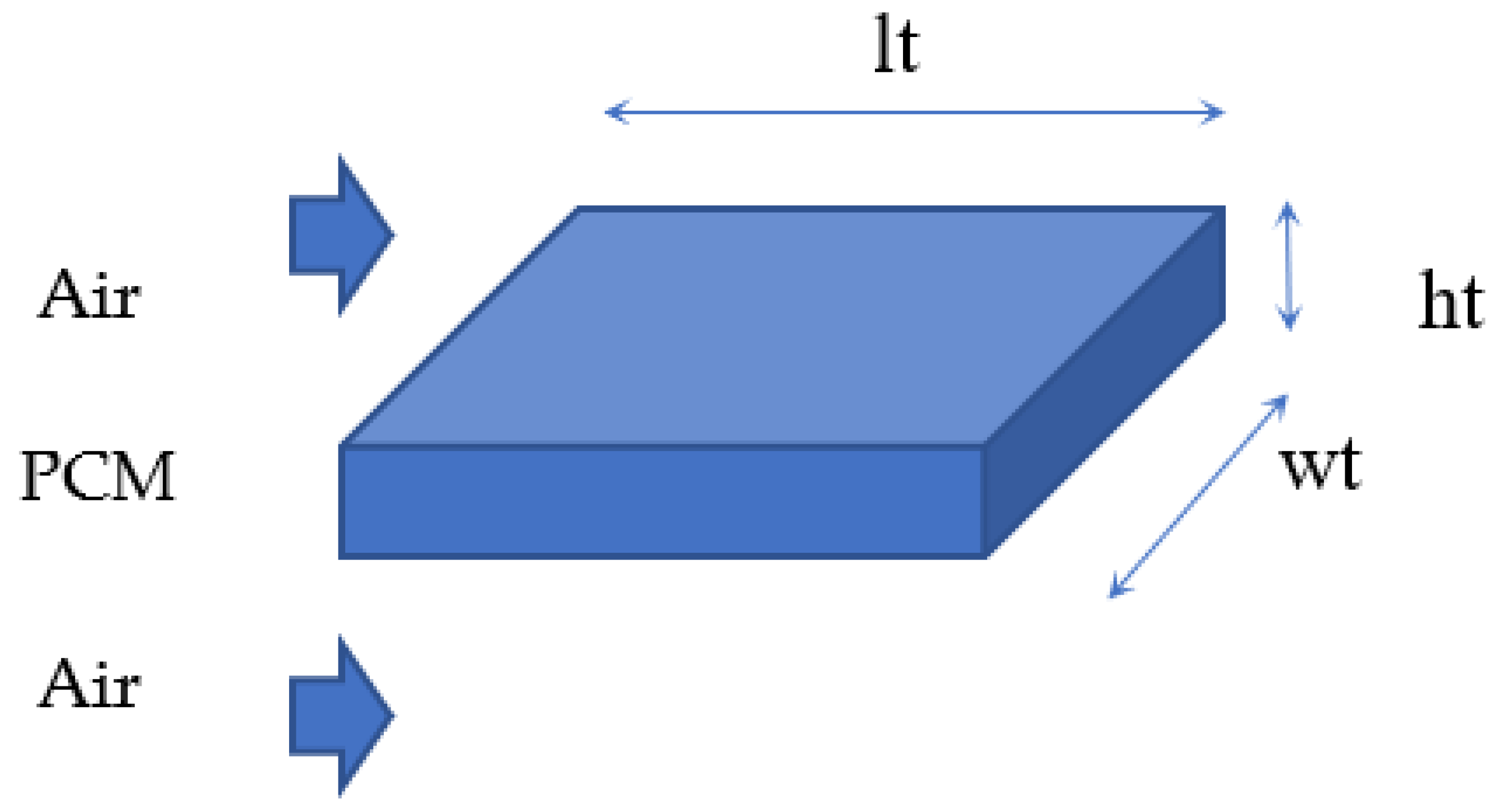
The simulation was validated with experimental data obtained by Zivkovic and Fujii [13] because its geometry was similar and the heating fluid (air) flowed in the sides of the container; moreover, a hexahydrate salt was also used as the PCM (CaCl2·6H2O). The rectangular container had a length (lt) and width (wt) = 0.1 m, and the height (ht) varied from 0.01 to 0.02 m (see Figure 3). Air flowed in the sides of the PCM as the heating medium.
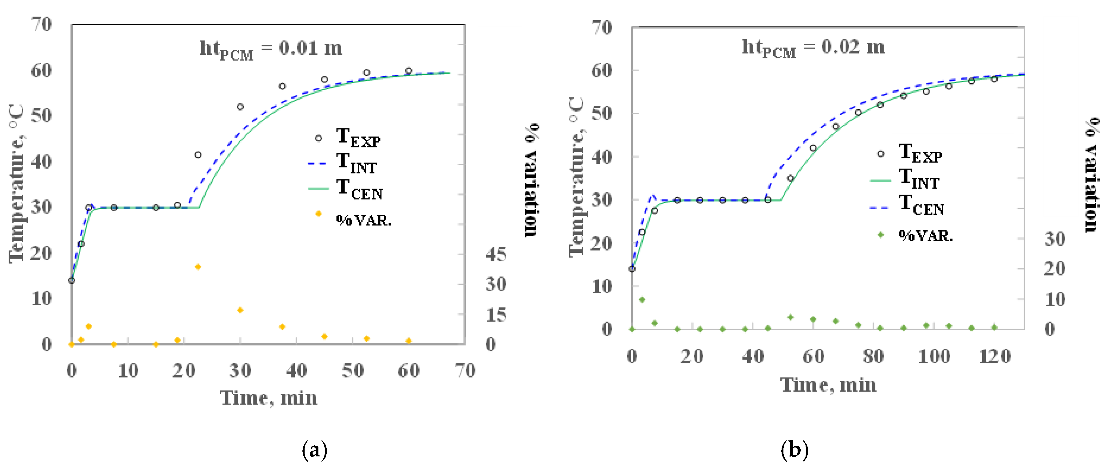
Figure 4 shows the temperature profiles at the output of the PCM container as a function of time. The initial temperature was 14 and 60 °C for the PCM container and air, respectively. The figure shows that the phase change finished after 20.70 and 22.67 min in the interphase (TINT) and center (TCEN) of the PCM, respectively, for htPCM = 0.01 m, and 45 and 49 min for ht = 0.02 m. This time delayed in the interphase and center occurred because the phase change was obtained first in the interphase, so the temperature is constant and heat transfer from the interphase and the center was low. Once the phase change finished in the interphase, the temperature started to increase and heat transfer increased from the interphase and center, and the phase change was completed within a short period of time. Moreover, it could be observed that the temperature increased faster in the liquid phase than in the vapor phase due mainly to the thermal conductivity. The temperature differences obtained between the experimental values (TEXP) and the simulation (in the center) were lower than 10% (see Figure 4); only two points yielded values higher than 15% at the beginning of the liquid phase at htPCM = 0.01 m, caused mainly by the lack of thermophysical properties in the phase change zone. However, similar temperature behavior was detected; moreover, the phase change time between the experimental data and simulation was less than 5 minutes for both thicknesses.

3. Methodology

The present study considers the cooling of a building via an H2O-LiBr single-stage absorption cooling system (ACS) using a parabolic trough collector which supplies thermal energy to the storage tank (SHST), as can be seen in Figure 5a. There are two main circuits: solar collector (red line) and cooling (magenta line). In the solar collector circuit, heating fluid is pumped from the SHST into the PTC and returned to the SHST. In the cooling circuit, the same heating fluid is sent to the auxiliary system to control the supply temperature to the generator component of the ACS and return to the tank. The auxiliary system consists of a heating system (HS) and a dissipating system (DS) in order to control the input temperature in the generator of the ACS from 111.0 to 116.1 °C.
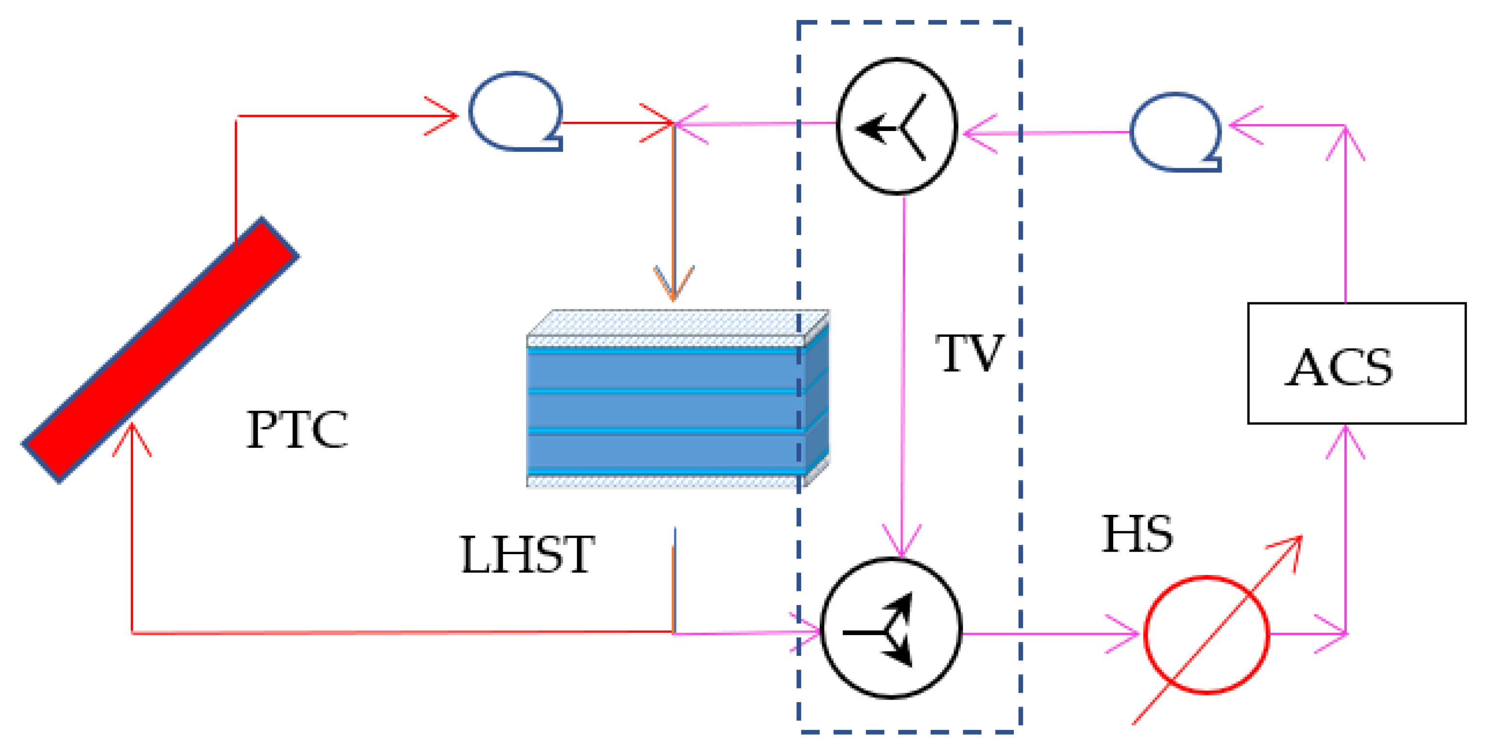
Three configurations are evaluated: the first uses a sensible heat storage tank (SHST), which means that there is no phase change (Figure 5a). The second configuration uses a latent heat storage tank (LHST), as can be seen in Figure 5b. Configuration 3 (Figure 6) uses an LHST and introduces a tempering valve (TV) that eliminates the dissipating system. The TV consist of a diverter and a mixer component and its objective is to keep the input temperature at the maximum range of operation (111 °C) when the temperature of the storage tank is higher than the limit of operation of the ACS. The function consists of mixing the stream resulting from the high temperature of the storage tank with a relatively low temperature stream coming from the ACS, changing the flow rates of each stream.

3.1. Operation Time

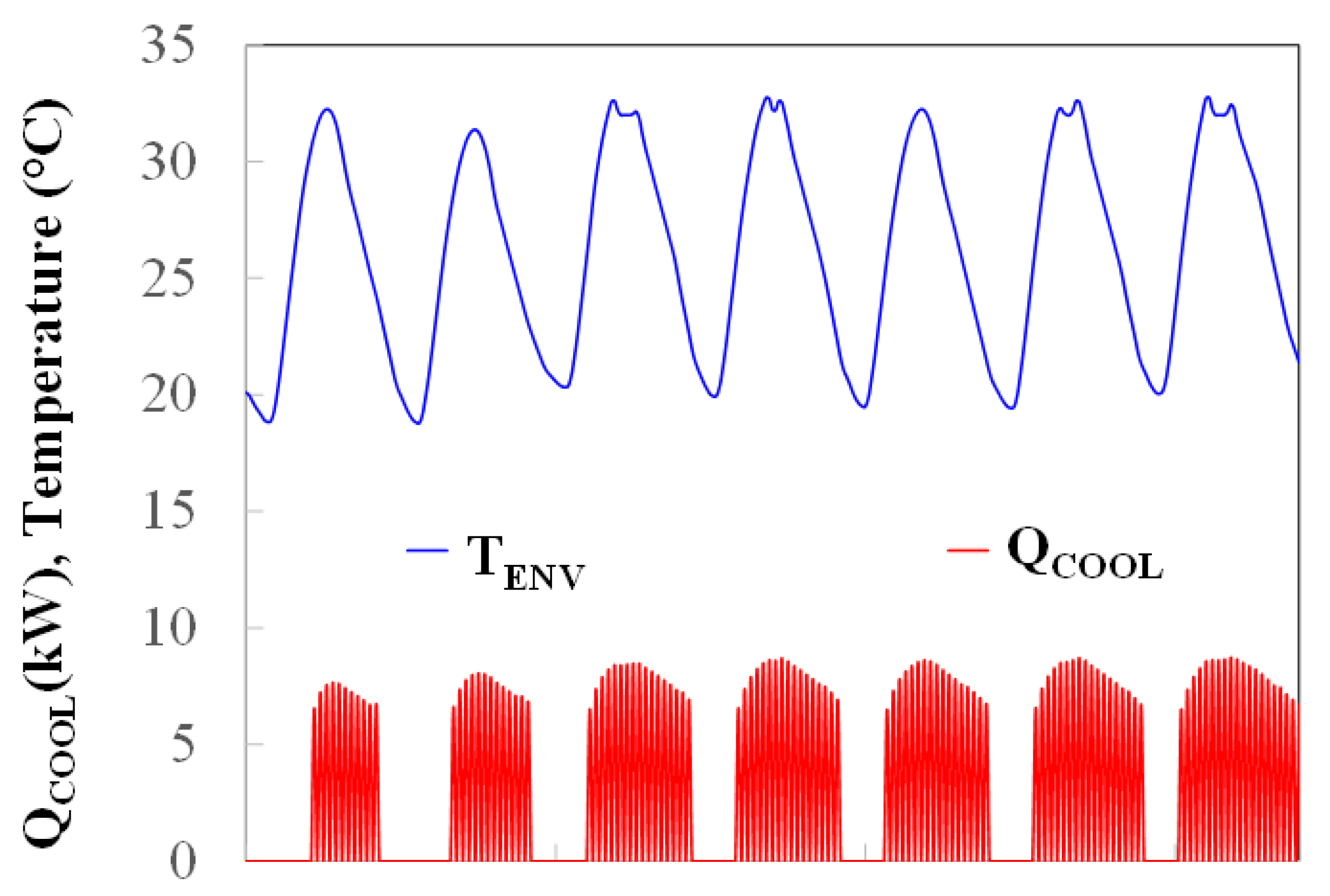
An analysis of the environmental conditions was carried out in order to select the time of operation of the ACS. Type 15-2 (weather data) was built in the TRaNsient SYstem Simulation (TRNSYS) software to simulate the environmental conditions of Temixco City, Morelos, Mexico. A typical week in summer was selected from 1996 to 2164, as Figure 7 shows. The environmental temperature (TENV) oscillates from around 32 to 20 °C (blue line). A building was simulated in a previous work [14]; some building characteristics are shown in Table 2. The maximum cooling demand (red line) was 8 kW. In addition, the figure shows that the cooling heat load is somewhat lower on the first day than on the others, which presents the opportunity to store energy in the storage tank.

3.2. Solar Cooling System Simulation

The TRNSYS [15] software was used to simulate the solar chiller for cooling a building. Figure 8 shows a schematic diagram of the process with the implementation of the TV (configuration 3). There are four main circuits: the solar collector (red line), heating tank (magenta line), chilled water (blue line), and cooling water (green line). In the solar collector circuit, a heating fluid is pumped (Type 3d-3) from a storage tank (Type 66a, programmed in the Equation Engineering Solver software [16]) into the PTC (Type 1288) and returned to the tank. In the heating storage circuit, the heating fluid is pumped (Type 3d-4) from the storage tank to the tempering valve (Type 62, programmed in Excel software) to the ACS (Type 107-2) to supply energy to the generator. When the temperature of the storage tank is lower than the minimum temperature of the working operation of the ACS, a heater (Type 6) is turned on.
The chilled water circuit is used to control the temperature of the building (Type 56) using a cooling thermostat (Type 1503) at 25 °C ± 1 °C. The chilled water is pumped (Type 3d) from the evaporator from the ACS (Type 107-2) to a heat exchanger (Type 91) and exchanges heat with the airflow rate (Type 3d-2) from the building and returns to the ACS. Finally, the cooling water circuit is used to extract the heat load from the condenser and absorber of the ACS. A water flow rate is pumped (Type 3d-5) from the ACS, and it is sent to a cooling tower (Type 510) which decreases its temperature, and it is returned to the chiller.
The pump in the solar circuit is controlled by Type 2b, and it is turned off when the output is higher than the input temperature of the storage tank or when the temperature of the tank reaches a maximum temperature of operation, namely 180 °C, to avoid high pressure when water is used as the heating fluid. The thermostat (Type 1503) controls the pumps in the heating tank, chilled water and cooling water circuits.
Details of the mathematical model of the heating tank, cooling and chilled water circuit can be found in Cerezo et al. [14]. Table 3 shows the parameters of the parabolic trough collector [17].
The solar fraction (SF) is defined in Equation (8).
SF = Q SC Q SC + Q HS
QSC and QHS represent the energy of the solar collector and the heating system in kJ.

4. Results

4.1. Thermal Analysis of the LHST

The storage tank was studied with two types of heating fluid: water and synthetic organic (SO) fluid [18]. Both heating fluids were analyzed because the PTC should supply temperatures up to 117°C to the PCM to reach a fusion latent state; then, the pressure vapor should present problems using water. Table 4 lists some of the thermal properties of the heating fluids. The pressure vapor of the SO is negligible compared to water; however, the thermal conductivity and heat capacity are lower than those of water.
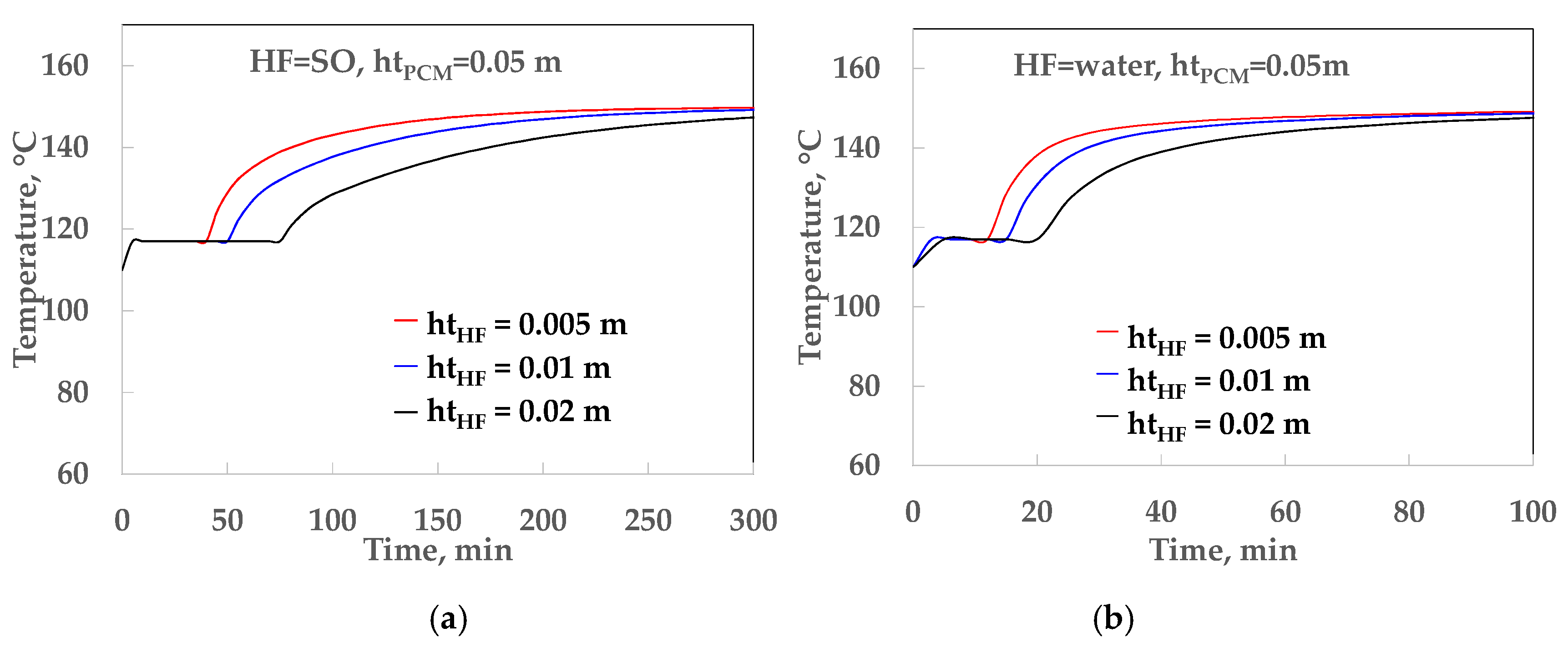
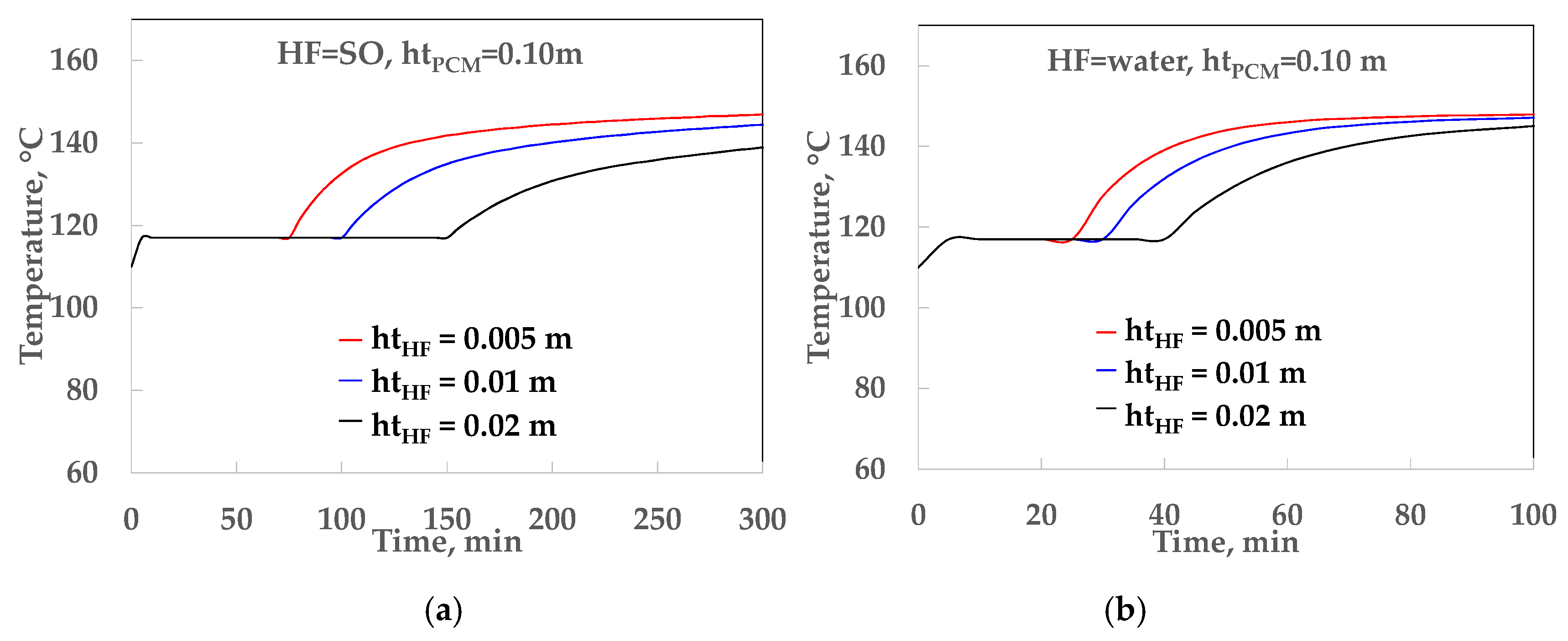
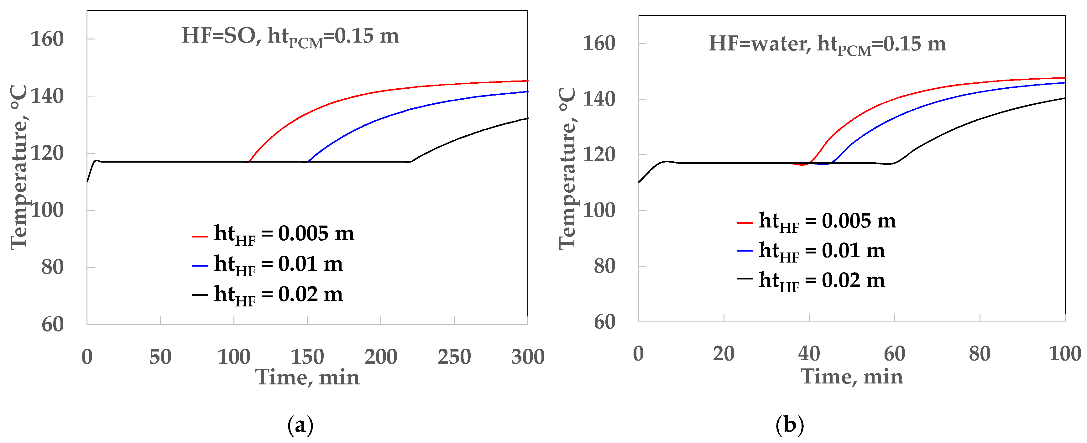
Figure 9, Figure 10 and Figure 11 show the temperature profiles of the heating fluids over time for an LHST with a geometry of length = 3 m and width = 0.5 at different heights for HF (htHF) and PCMs (htPCM). Figure 9 shows the temperature profile at htPCM = 0.05 m. It can be observed that when htHF is reduced, the phase change time is shorter and finishes at 40, 50 and 75 min for htHF = 0.005, 0.01 and 0.02 m, respectively, for SO. In the case of water, the phase change time is reduced significantly: it takes 12, 15 and 20 min to complete the process. Figure 10 and Figure 11 illustrate similar behavior to that shown in Figure 9; however, much more time is needed to complete phase change. A value of htHF = 0.005 m was used for the simulation of the absorption cooling system.
It was observed that water requires less phase change time than SO, due to the thermal resistance (TR) in the heating fluid. Table 5 shows the thermal resistances inside the LHST at different htPCM at a flow rate of 1200 kg/min, which corresponds to a convection transfer coefficient (hHF) of 0.09 and 0.52 kW/m2 °C for SO and water, respectively. It can be seen that the global heat transfer (U) is almost doubled when htPCM is 0.05 m for SO (0.050 kW/m2 °C) and water (0.094 kW/m2 °C); however, the difference in U values is reduced when htPCM is 0.15 m (0.027 and 0.035 kW/m2 °C). The U values were affected more noticeably by the water than SO. The reduction in U values ranged from 0.050 to 0.027 kW/m2 °C for SO and 0.094 to 0.035 kW/m2 °C when htPCM was increased. This means that the thermal resistance was more dominant in SO than water, because the convective resistance was lower in water than SO.
The storage tank sizes selected for this study were 0.25, 0.50 and 0.75 m3, which correspond to htPCM of 0.049, 0.10 and 0.16 m, respectively, at fixed widths of 0.5 m and lengths of 3 m.

4.2. Thermal Analyses of the Absorption Cooling System

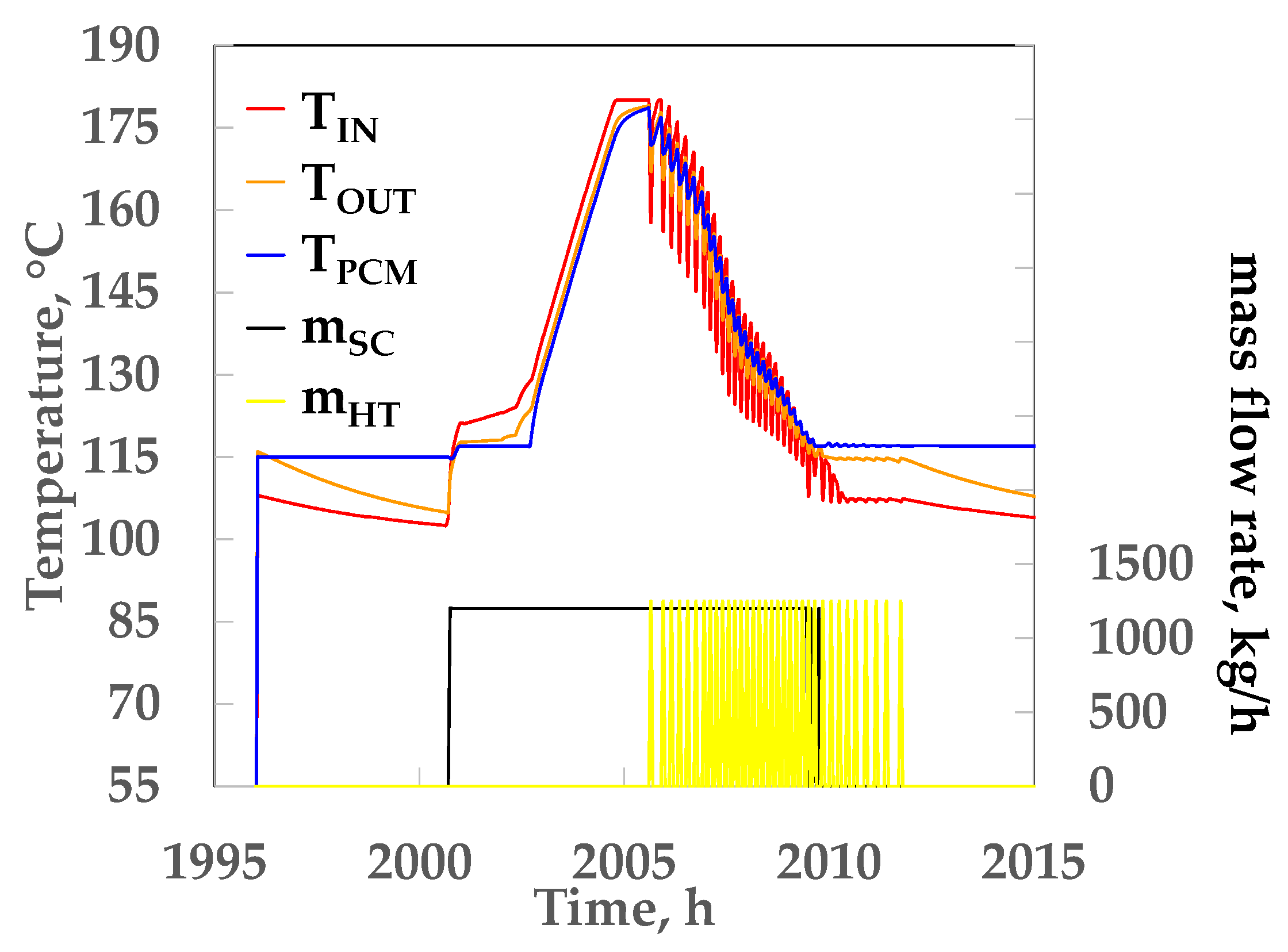
Figure 12 shows the behavior of the temperature and flow rates of the LHST from 1995 to 2015 h (around a day) for water, at a storage tank volume of 0.25 m3 and 20 m2 of the solar collector area. The operation of the solar absorption cooling system with LHST in dynamic condition can be explained in three steps: (1) only the solar collector flow rate (black line) is activated, (2) both the solar collector and the heating tank (yellow line) flow rate are activated and (3) heating tank flow rate is activated. The initial temperature of the PCM (TPCM) was 115 °C. In step 1, the input (red line) and output (orange line) temperatures started to increase at around 2001 h. The input (TIN) and output (TOUT) temperatures are the average temperatures of the solar collector and the heating tank circuits (described in Section 3.2). When the TPCM (blue line) reached 117 °C, the phase change began and lasted around two hours, after which the liquid phase started and the temperature began to increase. The second step started at around 2006 h when the flow rate of the solar collector and heating tank circuits entered the storage tank; then, the temperatures started to oscillate because the heating circuit flow rate was switched off or on every 12 or 18 min, depending on the ACS. The energy of the solar collector and storage tank was supplied to the generator of the ACS and temperatures started to decrease. The solar collector was switched off at around 2010 h and the third step began, with the energy supplied to the ACS coming from the storage tank or the heating system (when TOUT was less than 111 °C), and the process was completed at 2012 h.
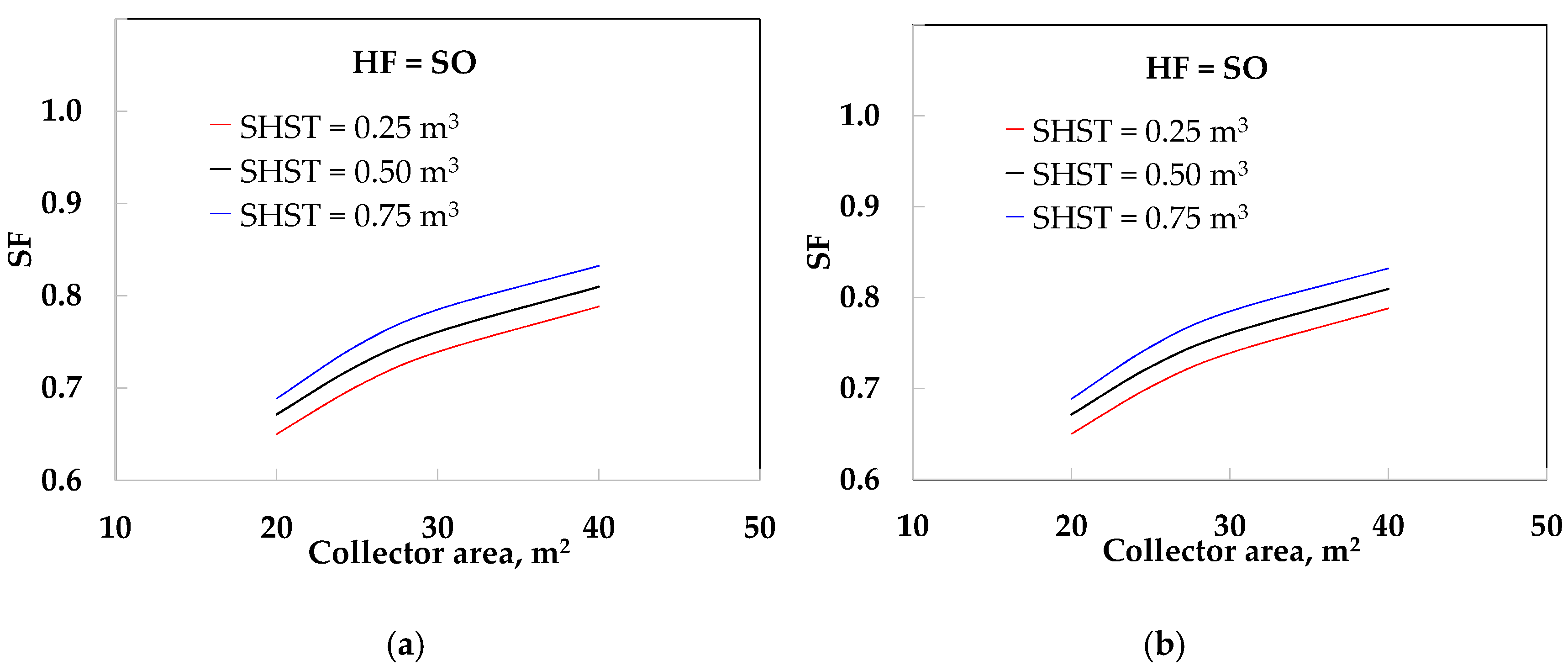
Figure 13 and Figure 14 show the behavior of the solar fraction when varying the solar collector area from 20 to 40 m2 at different sizes and with different heating fluids, using an SHST and LHST, respectively. The solar fraction increased when the storage tank size and solar collector area were increased in all cases. Figure 13 shows that the solar fraction (SF) increased from 0.65 to 0.79 for SO and from 0.66 to 0.80 for water at a storage tank volume of 0.25 m3, and it increased from 0.69 to 0.83 for SO and from 0.71 to 0.86 for water at 0.75 m3. The SF of the water yielded slightly better results (between 1.1 and 2.5%) than SO, because the heat capacity of the water was larger than that of SO (see Table 4) and the storage tank stored more energy. As is known, SHST is the conventional medium used to store thermal energy for absorption cooling systems. The energy used by the heating system was 5680 MJ for SO and 5120 MJ for water at 0.75 m3 with 40 m2, while the dissipation energy (waste energy) in the system amounted 1420 MJ for SO and 1640 MJ for water.
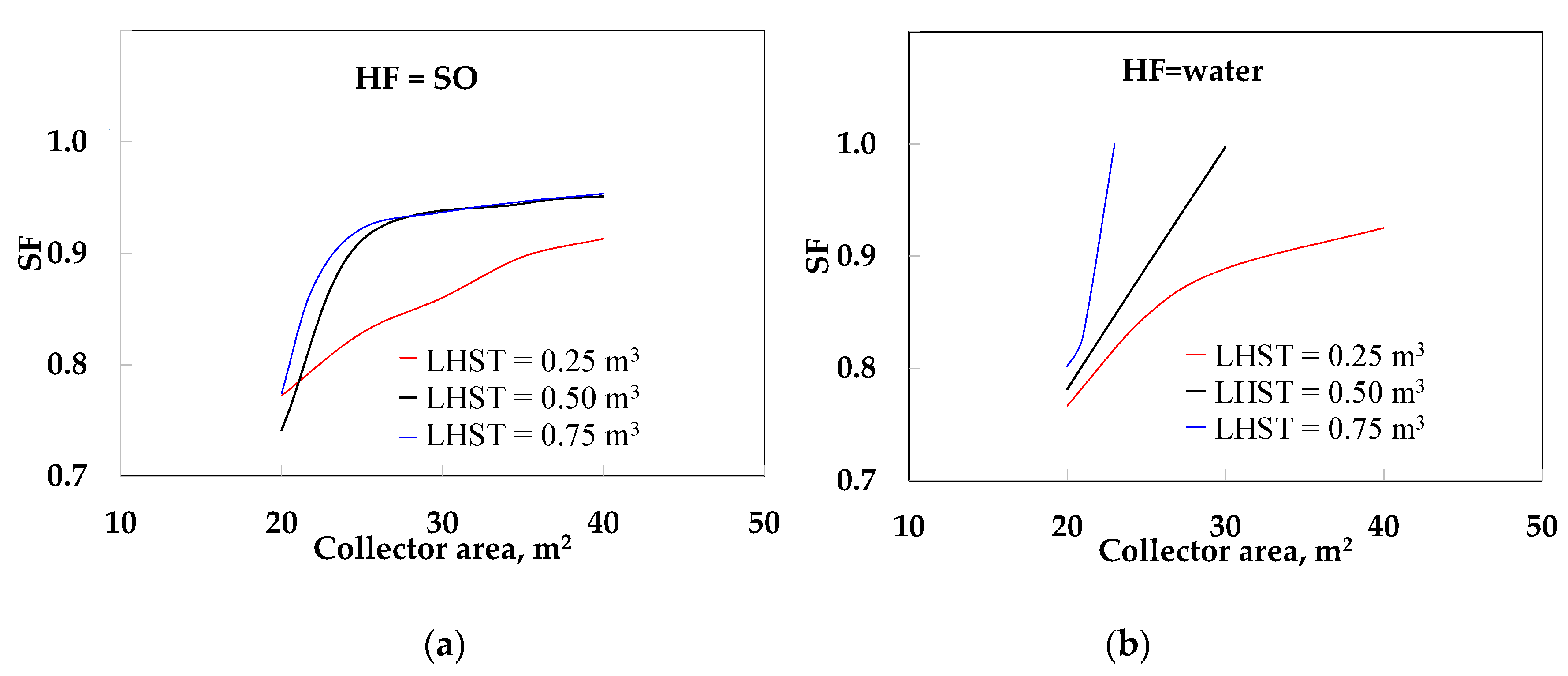
Figure 14a shows that the SF increased almost linearly from 0.77 to 0.91 for SO at 0.25 m3 from 20 to 40 m2. However, the SF increased rapidly from 0.74 to 0.93 and 0.77 to 0.93 for SO from 20 to 30 m2 at 0.50 and 0.75 m3, respectively. After this, similar values (from 0.93 to 0.95) were obtained at 0.50 and 0.75 m3 from 30 to 40 m2 due to the high thermal resistance in both the PCM and the HF. When water was used, the SF increased quickly from 0.77 to 0.89 from 20 to 30 m2 at 0.25 m3, and reached a maximum value of 0.93 at 40 m2 (slightly higher than SO under similar conditions) because the capacity to store energy was not sufficient to maintain the minimum working temperature of the ACS. However, when the LHST volume was 0.50 and 0.75 m3, the SF was 1.0 at 30 and 23 m2 of solar collector area, respectively. This is because the thermal resistance in HF was reduced from 11.11 to 1.92 m2 °C/kW (see Table 5). This improved the heat transfer of the LHST and the output temperature was higher than the minimum temperature required in the generator of the ACS (111 °C) and the heating system was not necessary. Moreover, water yielded better values of solar energy than SO because the input temperature in the PTC was lower than that when using SO.
Figure 15 shows the SF as a function of the solar collector area using the TV (configuration 3). The SF increased from 0.85 to 0.94 for SO at 0.25 m3 from 20 to 40 m2. Similar values of SF (0.90 to 0.96) were obtained for both 0.50 and 0.75 m3. However, when water was used, the SF increased from 0.88 to 0.99 at 0.25 m3, while the SF was 1.0 for 0.50 and 0.75 m3 when the collector area was greater than 20 m2.
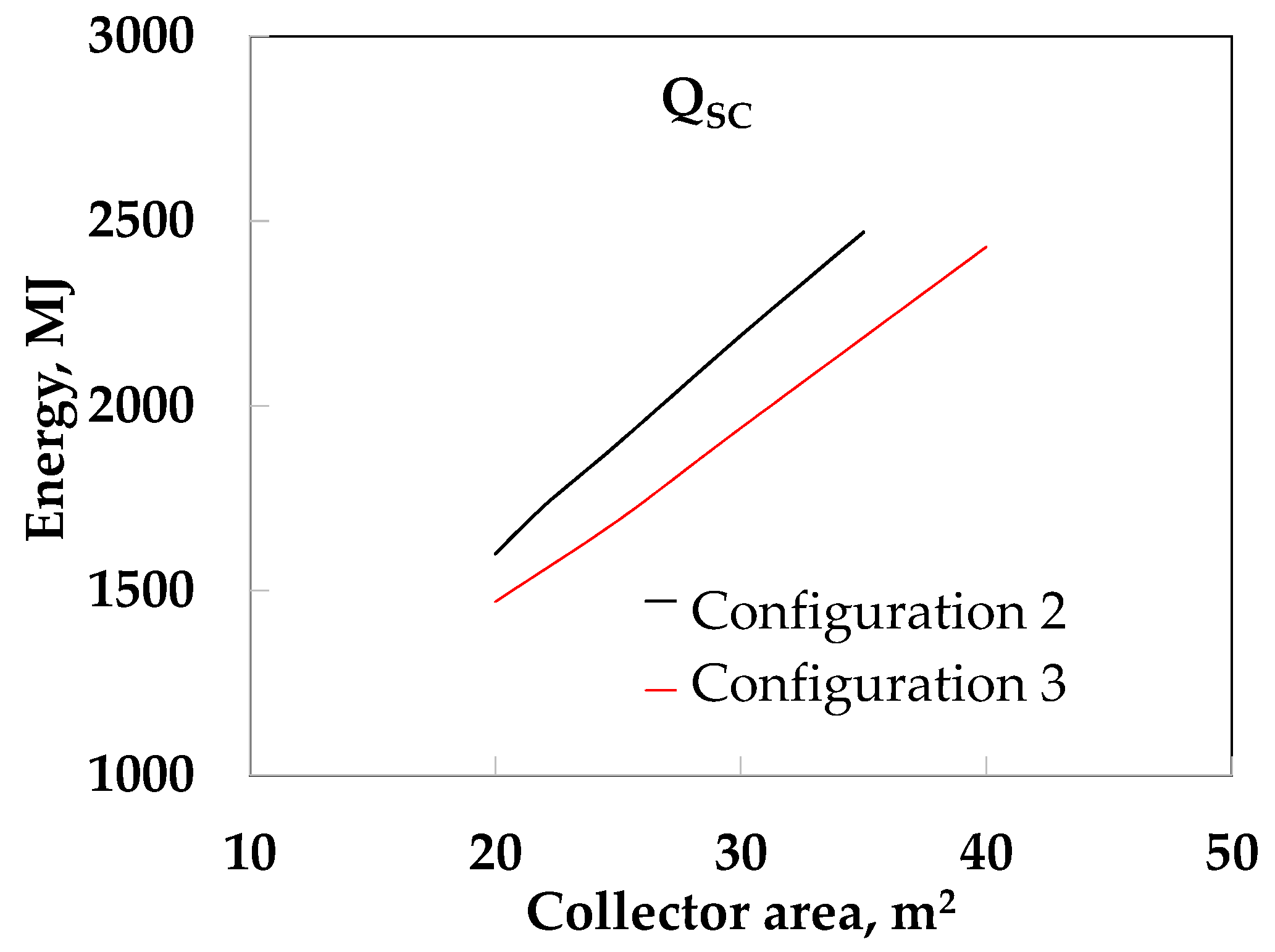
The SF yielded higher values with configuration 3 than configuration 2, mainly with a lower solar collector area, because it utilized the waste energy generated by the DS. The increment in the SF was slightly higher with configuration 3 than configuration 2 using SO above 30 m2; however, when water was used, the SF was very significant. This is because water extracted more energy than SO, and more energy remained stored in the storage tank with SO and it was not used when the absorption cooling system was activated. However, configuration 3 obtained a lower amount of solar energy from the solar collector than configuration 2 (see Figure 16) because the storage tank from configuration 3 reached a higher temperature than that in configuration 2 and reduced the efficiency of the solar collectors.

5. Discussion

Solar absorption cooling systems usually use sensible heat to store thermal energy in tanks because they are easy to build and the heat transfer is high because hot and cold streams are mixed directly, while LHST can store a large amount of energy due to the latent heat, but it is limited in terms of the thermal diffusion because the thermal conductivity in both PCM and HF is very low; however, the heat transfer can be improved by reducing the PCM thickness and increasing the convection transfer coefficient in HF, reducing the height of the channel.
The results of our study showed that the use of latent heat is more suitable than sensible heat. The use of water obtained better heat transfer of the LHST than SO, mainly due to the thermal conductivity; however, vapor pressure started to increase at temperatures above 100 °C, and the construction material in this case is more expensive. The advantages of the SO are the lower density compared to water and the very low vapor pressure (0.17 bar at 200 °C), which means that the thickness of the material can be reduced; however, the viscosity is almost three times higher than that of water and the convection resistance is high, which means that the solar collectors cannot satisfy the energy demand. The use of a corrugated plate heat exchanger could be used to improve the efficiency of the heat exchanger.
The ACS still cannot compete with compression vapor systems because the coefficient of operation is lower. This means that the ACS requires a greater energy supply; moreover, the necessity of cooling in the building is greater after roughly 3 pm due to the thermal inertial (depending on the building structure), when the solar radiation starts to decrease. Solar energy storage is crucial for absorption cooling systems. Sensible heat storage tanks commonly used in ACS cannot fulfill the energy requirements, necessitating external energy input from the auxiliary system; in addition, they are larger and heavy. However, our results showed that the energy supply to the ACS can rely only on the solar collector for the use of the LHST, which can store sufficient energy in small spaces as reported by Fan et al. [5]. This is a very important aspect to consider in order to increase the interest in this kind of sustainable technology.

6. Conclusions

This paper presented a thermal analysis of an absorption cooling system using three configurations: (1) an SHST, (2) an LHST, and (3) using LHST and TV; moreover, water and SO were tested as types of heating fluid. The following conclusions were made:
  • The use of SHST (configuration 1) yielded a solar fraction ranging from 0.65 to 0.79 and 0.69 to 0.83 for SO at 0.25 and 0.75 m3 storage tank volume, respectively, from 20 to 40 m2 of solar collector area, while a solar fraction from 0.66 to 0.80 and 0.71 to 0.86 was obtained for water under similar conditions.
  • The use of LHST (configuration 2) yielded better SF values than the use of SHST. When SO was used the SF increased almost linearly from 0.77 to 0.91 at 0.25 m3 from 20 to 40 m2, while the SF increased quickly at around 0.74 to 0.93 at 0.50 and 0.75 m3, respectively, from 20 to 30 m2. After this, similar values (from 0.93 to 0.95) were obtained, due to the high thermal resistance in both the PCM and the HF. When water was used, we obtained a maximum value of SF = 0.93 at 0.25 m3. However, the SF was 1.0 at 0.50 and 0. 75 m3 at 30 and 23 m2, respectively. This is because the thermal resistance in HF was reduced and improves the heat transfer of the LHST.
  • Configuration 3 (LHST and TV) yielded better results than configuration 2 because it used the waste energy generated by the DS (configuration 2). When SO was used, the SF increased from 0.85 to 0.94 at 0.25 m3. The SF obtained similar values (0.90 to 0.96) at 0.50 and 0.75 m3. When water was used, the SF increased from 0.88 to 0.99 at 0.25 m3; however, the SF was 1.0 at 0.5 and 0.75 m3, when the collector area was more than 20 m2.

Author Contributions

J.C. and F.L. carried out the mathematical model of the LHST, R.J.R. and A.R. developed the simulation of the ACS in TRNSYS, and F.L. supplied and analyzed the PTC. All authors have read and agreed to the published version of the manuscript.

Funding

This research received no external funding.

Institutional Review Board Statement

Not applicable.

Informed Consent Statement

Not applicable.

Conflicts of Interest

The authors declare no conflict of interest.

Nomenclature

Aarea: m2
DSdissipation system
Ddiameter
F´(τα)collector (F´) (transmittance) (absorptance) product
hconvective heat transfer coefficient, kW/m2 °C
HFheating fluid
HSheating system
Htheight
kthermal conductivity, kW/m °C
LHSTlatent heat storage tank
ltlength
mmass flow rate, kg/s
NuNusselt number
PCMphase change material
PrPrantl number
PTCparabolic trough collector
RaRayleigh number
ReReynolds number
SHSTsensible heat storage tank
Ttemperature, °C
ttime, s
ththickness
Qenergy
Uoverall heat transfer coefficient, kW/m2 °C
Vvolume, m3
wtwidth
Subscript
CENcenter
ENVenvironment
INSinsulating
INTinterphase between PCM container and HF
SCsolar collector
Hhydraulic

References

  1. The Organization for Economic Co-Operation and Development. Available online: https://www.oecd.org/about/publishing/TheFutureofCooling2018Corrigendumpages.pdf (accessed on 2 February 2021).
  2. Mofijur, M.; Mahlia, T.M.; Silitonga, A.S.; Ong, H.C.; Silakhori, M.; Hasan, M.H.; Putra, N.; Ashrafur, S.M. Phase Change Materials (PCM) for Solar Energy Usages and Storage: An Overview. Energies 2019, 12, 3167. [Google Scholar] [CrossRef] [Green Version]
  3. Sarbu, I.; Sebarchievici, C. A Comprehensive Review of Thermal Energy Storage. Sustainability 2018, 10, 191. [Google Scholar] [CrossRef] [Green Version]
  4. Shirazia, A.; Taylor, R.A.; Morrison, G.L.; White, S.D. Solar-powered absorption chillers: A comprehensive and critical review. Energy Convers. Manag. 2018, 171, 59–81. [Google Scholar] [CrossRef]
  5. Fan, Z.; Infante, C.A.; Mosaffa, A.H. Numerical modelling of high temperature latent heat thermal storage for solar application combining with double-effect H2O/LiBr absorption refrigeration system. Sol. Energy 2014, 110, 398–409. [Google Scholar] [CrossRef]
  6. Pintaldi, S.; Sethuvenkatraman, S.; White, S.; Rosengarten, G. Energetic evaluation of thermal energy storage options for high efficiency solar cooling systems. Appl. Energy 2017, 188, 160–177. [Google Scholar] [CrossRef]
  7. Zhou, L.; Li, X.; Zhao, Y.; Dai, Y. Performance assessment of a single/double hybrid effect absorption cooling system driven by linear Fresnel solar collectors with latent thermal storage. Sol. Energy 2017, 151, 82–94. [Google Scholar] [CrossRef]
  8. Cengel, Y.A. Heat and Mass Transfer: A Practical Approach, 2nd ed.; Mc Graw-Hill Professional: New York, NY, USA, 2007. [Google Scholar]
  9. Cárdenas, B.; León, N. High temperature latent heat thermal energy storage: Phase change materials, design considerations and performance enhancement techniques. Renew. Sustain. Energy Rev. 2013, 27, 724–737. [Google Scholar] [CrossRef]
  10. Chejne, F. Solar Thermal Energy Storage Using Magnesium Chloride Hexahydrate. Ph.D. Thesis, Universidad Nacional de Colombia, Medellín, Colombia, 2007. (In Spanish). [Google Scholar]
  11. Kenisarin, M.; Mahkamov, K. Solar energy storage using phase change materials. Renew. Sustain. Energy 2007, 11, 1913–1965. [Google Scholar] [CrossRef]
  12. Höhlein, S.; König, A.; Brüggemann, D. Thermophysical characterization of MgCl2·6H2O, xylitol and erythritol as phase change materials (PCM) for Latent Heat Thermal Energy Storage (LHTES). Materials 2017, 10, 444. [Google Scholar] [CrossRef] [PubMed] [Green Version]
  13. Zivkovic, B.; Fujii, I. An analysis of isothermal phase change of phase change material within rectangular and cylindrical containers. Sol. Energy 2001, 70, 51–61. [Google Scholar] [CrossRef]
  14. Cerezo, J.; Romero, R.J.; Ibarra, J.; Rodríguez, A.; Montero, G.; Acuña, A. Dynamic simulation of an absorption cooling system with different working mixtures. Energies 2018, 12, 259. [Google Scholar] [CrossRef] [Green Version]
  15. Solar Energy Laboratory. TRNSYS 18, A Transient System Simulation Program. Available online: http://sel.me.wisc.edu/trnsys (accessed on 2 February 2021).
  16. Klein, S.A. EES, Engineering Equation Solver; Professional Version; FChart Software: Madison, WI, USA, 2017; Available online: http://www.fchart.com/ees/ (accessed on 2 February 2021).
  17. Technical Data. Solar Concentration Model LH-3-2M, Solar Rating & Certification Corporation 2018. Available online: https://solar-rating.org/ (accessed on 2 February 2021).
  18. Dowthermtm Q Technical Data Sheet. Available online: https://www.dow.com/content/dam/dcc/documents/en-us/productdatasheet/176/176-01467-01-dowtherm-q-tds.pdf?iframe=true (accessed on 2 February 2021).
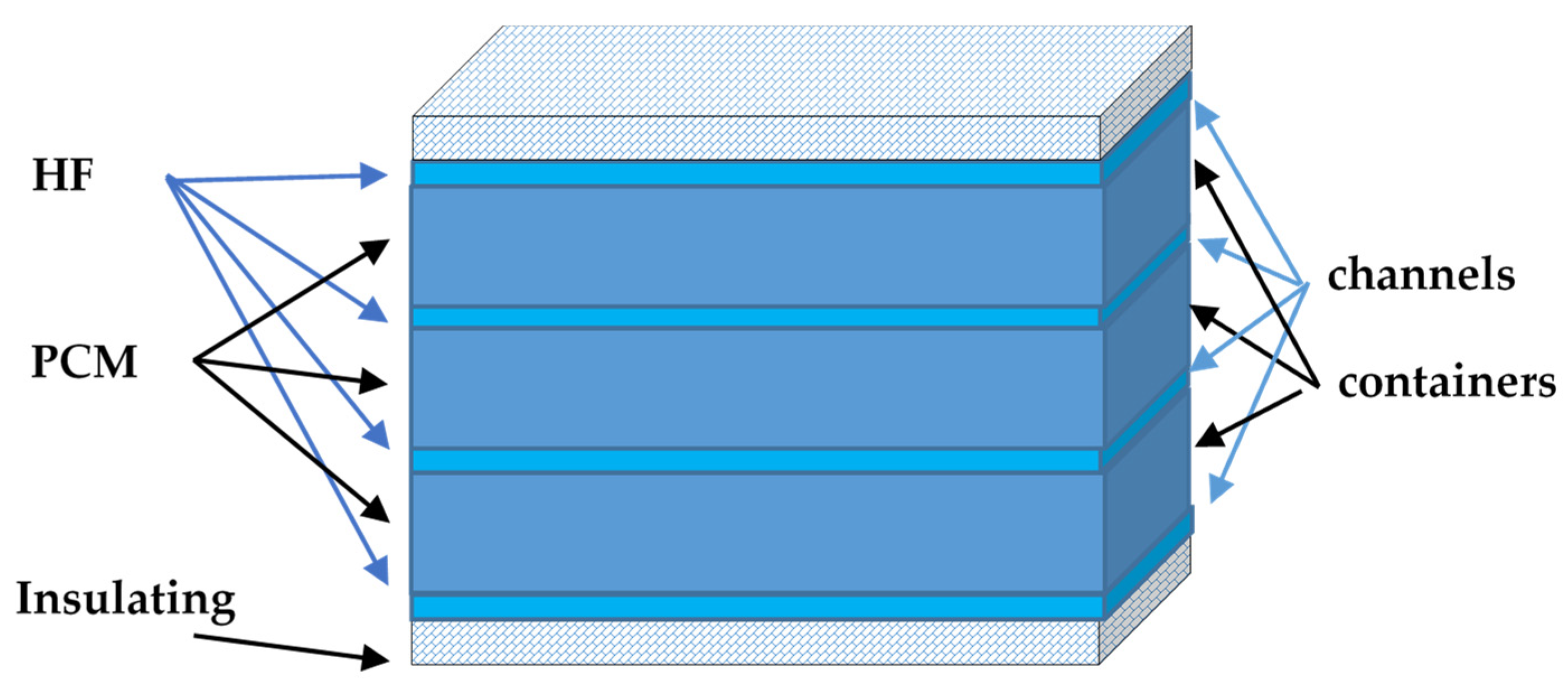
Figure 1. Schematic of the rectangular latent heat storage tank.
Energies 14 01376 g001
Figure 2. Schematic discretization of (a) the rectangular container of the LHST; (b) the volume element of a node (m, n).
Energies 14 01376 g002
Figure 3. Validation of the rectangular container with CaCl2·6H2O.
Energies 14 01376 g003
Figure 4. Validation of the simulation of a rectangular container at a PCM height of (a) 0.01 m and (b) 0.02 m.
Energies 14 01376 g004
Figure 5. Solar cooling system with (a) sensible heat and (b) latent heat storage tank.
Energies 14 01376 g005
Figure 6. Solar cooling system with latent heat storage tank and a tempering valve.
Energies 14 01376 g006
Figure 7. Environmental temperature behavior over one week.
Energies 14 01376 g007
Figure 8. Diagram of the solar cooling system in TRaNsient SYstem Simulation (TRNSYS).
Energies 14 01376 g008
Figure 9. Temperature profile over time for a height of PCM = 0.05 m using (a) SO and (b) water.
Energies 14 01376 g009
Figure 10. Temperature profile over time for a height of PCM = 0.10 m using (a) SO and (b) water.
Energies 14 01376 g010
Figure 11. Temperature profile over time for a height of PCM = 0.15 m using (a) SO and (b) water.
Energies 14 01376 g011
Figure 12. Temperature profiles and flow rates of LHST for water at 0.25 m3 and 20 m2.
Energies 14 01376 g012
Figure 13. Solar fraction as a function of parabolic trough collector (PTC) collector area for sensible heat storage tank (SHST) (configuration 1) using (a) SO and (b) water.
Energies 14 01376 g013
Figure 14. Solar fraction as a function of PTC collector area for LHST (configuration 2) using (a) SO and (b) water.
Energies 14 01376 g014
Figure 15. Solar fraction against PTC collector area for LHST with a tempering valve (configuration 3) using (a) SO and (b) water.
Energies 14 01376 g015
Figure 16. Solar energy against solar collector area at LHST volume of 0.75 m3.
Energies 14 01376 g016
Table 1. Thermophysical properties of some Phase change materials (PCMs) [9,10,12,13].
CompoundMelting
Temperature,
°C
Heat of Fusion,
kJ/kg
Thermal
Conductivity,
W/m °C
Density, kg/m3
Inorganic
MgCl2·6H2O117168.60.69 (solid)
0.57 (liquid)
1569 (solid)
1450 (liquid)
Mg(NO3)2·6H2O89162.00.61 (solid)
0.49 (liquid)
1636 (solid)
1550 (liquid)
CaCl2·6H2O29190.81.09 (solid)
0.53 (liquid)
1710 (solid)
1530 (liquid)
Organic
Paraffin wax64173.60.346 (solid)
0.167 (liquid)
916 (solid)
790 (liquid)
Naphthalene80147.70.341 (solid)
0.132 (liquid)
1145 (solid)
976 (liquid)
Table 2. Building characteristics.
ConceptQuantity
North and south wall35 m2
Ceiling and floor75 m2
West and east wall12.5 m2
4 windows1 m2
Air change of ventilation6 h−1
Table 3. Parabolic trough collector data.
ParameterValue
F’(τα)0.611
Collector efficiency coefficient, C11.42
Collector efficiency coefficient, C20.021
Collector efficiency coefficient, C30.0
Collector efficiency coefficient, C40.0
Collector efficiency coefficient, C56.653
Collector efficiency coefficient, C60.0
Table 4. Thermal properties of water and synthetic organic.
Property at 120 °CWaterSynthetic Organic
Heat capacity, kJ/kg °C4.251.97
Thermal conductivity, kW/m °C0.670.11
Pressure vapor, bar1.980.01
Density, kg/m3943.2889.8
Viscosity, centipoise0.230.62
Table 5. Thermal resistances (TRs) in the latent heat storage tank (LHST).
HFhHF,
kW/m2 °C
htPCM,
m
TRHF,
m2 °C/kW
TRPCM,
m2 °C/kW
U,
kW/m2 °C
SO0.090.0511.118.770.050
SO0.090.1011.1115.540.035
SO0.090.1511.1126.320.027
water0.520.051.928.770.094
water0.520.101.9217.540.051
water0.520.151.9226.320.035
Publisher’s Note: MDPI stays neutral with regard to jurisdictional claims in published maps and institutional affiliations.