Article

Design and Analysis of a While-Drilling Energy-Harvesting Device Based on Piezoelectric Effect

1
Faculty of Engineering, China University of Geosciences, Wuhan 430074, China
2
Research Institute No. 717, Shipbuilding Industry Corporation, Wuhan National Laboratory for Optoelectronics, Wuhan 430074, China
*
Author to whom correspondence should be addressed.
Energies 2021, 14(5), 1266; https://doi.org/10.3390/en14051266
Submission received: 3 February 2021 / Revised: 22 February 2021 / Accepted: 22 February 2021 / Published: 25 February 2021

Abstract

:
A while-drilling energy harvesting device is designed in this paper to recovery energy along with the longitudinal vibration of the drill pipes, aiming to serve as a continuous power supply for downhole instruments during the drilling procedure. Radial size of the energy harvesting device is determined through the drilling engineering field experience and geological survey reports. A piezoelectric coupling model based on the selected piezoelectric material was established via COMSOL Multiphysics numerical simulation. The forced vibration was analyzed to determine the piezoelectric patch length range and their best installation positions. Modal analysis and frequency response research indicate that the natural frequency of the piezoelectric cantilever beam increased monotonously with the increase of the piezoelectric patch’ thickness before reaching an inflection point. Moreover, the simulation results imply that the peak voltage of the harvested energy varied in a regional manner with the increase of the piezoelectric patches. When the thickness of the piezoelectric patches was 1.2–1.4 mm, the designed device gained the best energy harvest performance with a peak voltage of 15–40 V. Works in this paper provide theoretical support and design reference for the application of the piezoelectric material in the drilling field.

1. Introduction

Human society’s demand for energy has been increasing since the 20th century. Drilling engineering plays an important and irreplaceable role in the exploration and exploitation of coal, oil, geothermal and other energy resources. With the increase of the drilling depth and the complexity of the borehole structure, measurement while drilling (MWD) system and other downhole equipment has become an essential and auxiliary means to ensure the security and successfully accomplishment of an exploration and exploitation activity [1,2]. For example, the mud pulse MWD system is widely used in oil drilling. The electromagnetic MWD system for gas drilling has made substantial progress in recent years [3]. These underground MWD systems and other downhole equipment are usually powered by lithium batteries at present [4]. However, as the drilling depth increases, the underground environment becomes complex and has characteristics of high temperature and high pressure [5]. The complex underground environment would affect the lithium batteries’ performance, resulting in a greatly shortened power supply time and even power supply failure. Another alternative power supply method is known as the downhole turbine generators for its advantages of large power generation and high-temperature resistance [6]. However, downhole turbine generators have a complex structure and certain restrictions on mud flow rate. Moreover, the turbine would be easily damaged for large flow rates [7]. How to provide a continuous and stable energy supply for downhole equipment and MWD systems while drilling has become a new research hotspot [8].
Vibration energy is usually developed to provide power for wireless microelectronics equipment owing to the advantage of widespread energy, simple structure, high-energy-density, stable output, and easy integration [9]. During the drilling procedure, as the drill bit penetrates into the rock formation, the drill bit is subjected to reaction forces from the rock formation. Thus, the drill pipe would generate recoverable elastic deformation in the axial direction, namely longitudinal vibration, is produced [10]. Characteristics of this longitudinal vibration are highly related to the rock stiffness coefficient and natural frequency of the drill pipe [11]. Thus, the drilling activity would be continuous and relatively stable in the stratum with the same or similar lithology. If the energy along with longitudinal vibration of the drill pipe could be harvested, it would be a new approach to provide power for the MWD system and the other downhole equipment.
The unique property of the piezoelectric material has gained extensive attention since it was first discovered in the 20th century. The energy conversion principle of the piezoelectric vibration energy harvester is based on the piezoelectric effect, which can convert mechanical energy into electrical energy [12]. In other words, under the action of external forces, piezoelectric material would have a deformation. The deformation would result in a decrease of bound charge spacing and polarization strength between the internal positive and negative poles [13]. Thus, the free charge originally absorbed at the electrode would be released, resulting in a phenomenon of discharge [14,15,16].
In the aspect of using piezoelectric materials to collect and harvest vibration energy, various studies have been carried out in recent years. Gong Junjie and Ruan Zhilin [17] et al. investigated the influence of the external excitation’s frequency and amplitude on the power generation capacity of a multi-layer cantilever piezoelectric power generation device through finite element model analysis. J. Rastegar showed that the piezoelectric materials could be used in low-frequency vibration environments [18]. Wang Qiang [19] analyzed a force-electric equivalent model of the piezoelectric materials under vibration conditions and proved that the piezoelectric materials could be used in irregular vibration environments. Varadha et al. explored and reported a wind-driven thin-film piezoelectric energy harvester for both parallel and reticulate venation as well as for without venation [20]. Subbaramaiah et al. designed a vibration-sourced piezoelectric harvester for battery-powered smart road sensor systems [21].
The above research has shown that the piezoelectric material plays an increasingly important role in plenty of fields, including electronics, sound, light and transportation and so on. However, there are no reports about the applications of piezoelectric materials in the drilling field so far. The research mentioned above provides a certain theoretical foundation to the piezoelectric vibration energy harvester into drilling engineering. Compared with turbine power generation [6], piezoelectric energy collection and harvesting devices may generate less electricity. However, the piezoelectric energy collection method has plenty of advantages, such as that its power generation principle is simpler, and it has no special requirements on the drilling fluid. Obviously, it is an economical and environmental protection power generation method. Employment of the piezoelectric energy collection approach to the drilling industry could not only solve the problem of continuous power supply of downhole instruments well but also would develop a new application field and development space for the piezoelectric materials.
Due to the limitations of materials, the power generation capacity of the piezoelectric energy collection device is limited [22]. In order to increase the power generation capacity, the traditional piezoelectric energy harvesting approach mostly employed long cantilever beam structures to increase the size of the piezoelectric plate [23]. However, the annular space of a drilling borehole is usually limited [24]. Therefore, the commonly used long cantilever beam structure is difficult to be directly applied in drilling engineering. In addition, space for the drilling fluid should be ensured in the drilling engineering, for the drilling fluid serve many purposes, including transmitting power to the bit and returning the drilled cuttings to the surface [25]. Thus, enclosed shell of the commonly used long cantilever beam structure could not provide flow path for the drilling fluid. Obviously, the traditional piezoelectric energy harvesting structures need to be modified to make it more suitable for the actual drilling working conditions. Therefore, a new type of the drilling-while energy recovery device based on the piezoelectric material is designed and analyzed in this paper. Moreover, optimum size of the device, the optimum location and thickness of the piezoelectric plate, and the power generation performance are studied and determined based on COMSOL Multiphysics numerical simulations.
The remainder of this paper is organized as follows: Section 2 conducts the structural and functional design of the while-drilling energy harvesting device. Then, the principle and physical model of the power generation is established in detail in Section 3. Section 4 describes the piezoelectric design and analysis in detail, in which the Piezo material selection, length and position design of the piezoelectric element and the thickness analysis and optimization of the piezoelectric patches are discussed. Finally, the paper is closed by recapitulating salient points and concluding remarks in Section 5.

2. Structural and Functional Design of the While-Drilling Energy Harvesting Device

The structure and main components of the while-drilling energy harvesting device were designed as shown in Figure 1 and Figure 2. The device consists of three main structures, namely the cylinder upper-end, the cylinder bottom-end and the energy-capturing plate. Each structure is made up of several components, as shown in Table 1. As it is a downhole energy recovery device during the drilling activity, the device needs to undertake the part function of the drill pipe. In order to prevent underground accidents such as fracture, rod pipe stripping, some components (such as shells and joints) should have the same material and structure with the connecting upper and lower drill pipe.
During assembly, the inner race of the captive harvesting block is first connected to the lower well casing by a fixed thread. Then, the upper well casing is put into the lower well casing, and the upper and lower well casing is connected by an interference fit connection. Finally, the cylinder body upper-end and bottom-end are connected as a whole with fixing thread. The proposed device is connected to the drill pipe via the upper and lower drill pipe joints. The structure and size of joints in the device are designed to be consistent with that of the female and male screw of the drill pipe. The upper and lower well casing tubes are welded to the inner surface of the shell, which has a through-hole with the same inner diameter as that of the drilling pipe. Thus, a flow path for the drilling fluid could be provided by this through-hole for the proposed device. In addition, the whole device could transmit torque when drilling and protect internal components in complex downhole environments. When the drill bit penetrates into the rock formation, the bit vibrates longitudinally under the rock reaction. The drill pipe connected to the drill bit thus also has a longitudinal vibration. The longitudinal vibration of the drill pipe transfers from the lower drill pipe joint to the lower well casing and then to the energy harvesting plate. Under the amplification effect of the annular mass block, the cantilever beam attached with the piezoelectric plate vibrates and generates deformation. The deformation drives the piezoelectric plate to generate a positive piezoelectric effect, resulting in a charge release phenomenon. The generated electric energy is stored through the capacitor attached to the inner ring. In this way, the energy generated along with the longitudinal vibration of the drill pipe is converted and collected as electric energy.
From the above structural design and analysis, it is obvious that the proposed device improves the structure of the traditional piezoelectric vibration-energy collection device. It adopted a plate-type energy-capture structure together with a barrel shell structure to make full use of the annular space of the borehole. The proposed device could assume all the functions of a drill pipe in the drilling process. In other words, the device could accomplish the energy conversion and collection work without affecting the normal drilling operations. Moreover, each component of the device is mainly connected to other components through a thread connection. The proposed device owns plenty of advantages, such as has a simple structure, dis-assembly and repair convenience, and could be easily adapted to the site’s complex working environment.

3. Principle and Physical Model of Power Generation

Piezoelectric materials perform force-electricity conversion through the normal piezoelectric effect [26]. The piezoelectric strain constant of a certain material, d, is a physical constant related to the strain direction. It is the axial vibration of the piezoelectric materials that mainly works; thus, constant of this energy harvesting device is donated as d 33 . The piezoelectric square can be obtained under mechanical freedom and electrical short circuit, namely the first boundary condition [27].
S = S E T + d 33 T E
D = d 33 T + ε T E
In which D and E are the electric displacement (C/m2) and electric field intensity (N/C), respectively. The strain and stress of the piezoelectric patches are donated as S and T, respectively.   d 33 represents for axial piezoelectric constant matrix. S E stands for flexibility matrix. Moreover, ε T represents electric constant matrix.
The proposed device described above has a circular structure composed of four symmetrically distributed cantilever beams. The geometries, sizes, and materials of the four cantilevers are exactly the same as each other. Therefore, it is suitable to analyze one of the cantilever beams to simplify the analysis procedure. The energy generation component structure can be simplified and considered as a typical mass elasto-resistance model. According to the vibration situation and Newton’s second law, the dynamic equation can be obtained as following [28,29]:
K e q P ( t ) + θ V ( t ) = M e q S ¨ ( t ) + ζ e q S ˙ ( t ) + K e q S ( t )
In the above equation, K e q ,   M e q   and ζ e q stand for the equivalent stiffness, equivalent mass and equivalent displacement of a cantilever beam attached with the piezoelectric patches, respectively. θ is the electromechanical coupling coefficient of the selected piezoelectric material. V ( t ) stands for the output voltage.   P ( t ) stands for the external excitation. The external excitation is the cantilever beam displacement near the end of the inner ring, which is caused by the drilling pipe vibration environment. S ( t ) represents for the displacement at one end of the mass block.

4. Radial Dimension Design of the Proposed Device

The device works while drilling in the borehole; therefore, its radial size is limited by the borehole’s radial size. In order to leave space for the return fluid and cuttings, the shell diameter is designed smaller than the outside diameter of the bit. Moreover, in order to reduce the scraping and collision with the borehole walls, centralizers are essential for the bottom hole assembly. As the API standards are mostly used in the drilling construction for petroleum, geothermal and other fields, appropriate sizes can be selected according to actual construction requirements.
In order to ensure the general applicability of the results, the shell diameter is set as 320.7 mm for subsequent analysis and calculation. The outer diameter of the drilling bit used together with the designed device should be larger. To ensure smooth flow of the drilling fluid, the bore diameter of the well pipe should be the same as that of the through-hole in the shell but slightly lower than the drill pipe diameter. Because of the interference fit connection, the inner diameter of the lower well pipe should be slightly larger than the outer diameter of the upper one. The internal well pipe does not undertake torque transfer or other mechanical functions. Thus, the wall thickness of the well pipe can be correspondingly reduced. Under the condition of using a standard drill pipe with an outer diameter of 139.7 mm, the radial size of each component is designed as shown in Table 2.

5. Piezoelectric Design and Analysis

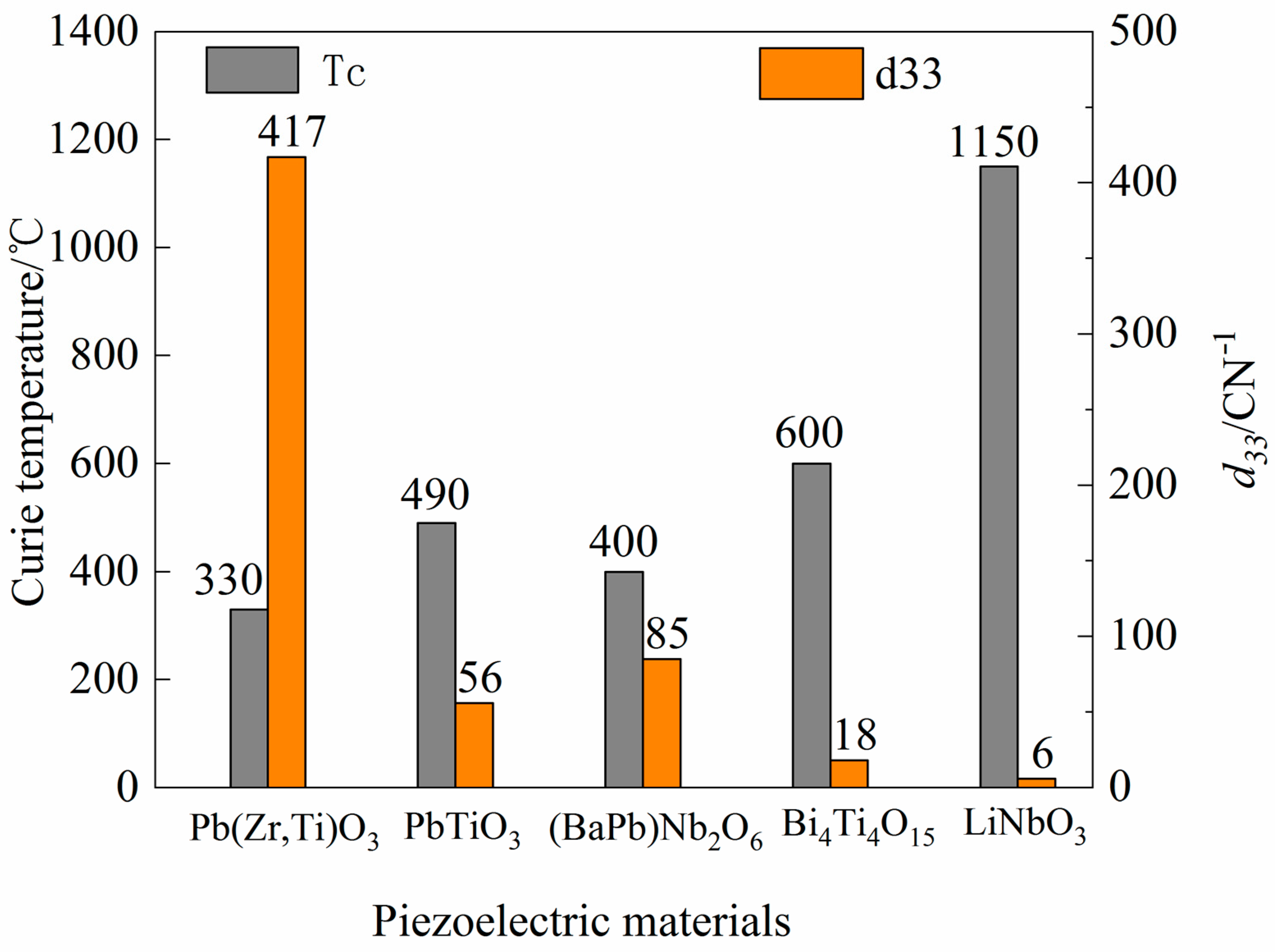
5.1. Piezo Material Selection

The energy harvesting procedure is realized by the piezoelectric materials in this work. As the drilling depth increase, the downhole working device usually encounters a high-temperature environment due to the influence of the geothermal gradient. When designing the energy harvest device for downhole equipment, it must be ensured that the piezoelectric element would not be depolarized by the impact of the high temperature. Therefore, the Curie temperature of the material should be more than twice the ambient temperature [30]. Curie temperature Tc and d33 values of several common high-temperature piezoelectric materials are shown in Figure 3. The piezoelectric material Pb(Zr,Ti)O3, known as PZT piezoelectric ceramics, owns good piezoelectric properties and a high dielectric constant, thus has been used extensively now. PbTiO3 is also a piezoelectric ceramics and is a promising high-temperature piezoelectric material with high piezoelectric properties and good anisotropy. However, PbTiO3 has manufacturing difficulties for microcracks appearance and polarization difficulty in its sintering process. (BaPb)Nb2O6 has a high hydrostatic piezoelectric performance and has been widely used in the field of ultrasonic nondestructive testing and medical diagnosis, but also has some disadvantages, such as low piezoelectric property, low electromechanical coupling coefficient and sintering difficulty. Bi4Ti4O3 has an interestingly layered structure and has strong spontaneous polarization, high resistivity, piezoelectric anisotropy and good temperature stability. However, Bi4Ti4O3 has low piezoelectric activity, and its manufacturing quality is difficult to guarantee. LiNbO3 combines high Curie temperature and large piezoelectric properties but is sensitive to heat and has poor thermal stability.
Geological survey data show that the geothermal gradient in most areas of China is 1.4–3.0 °C/100 m. The geothermal temperature at 5000 m underground is mostly 105–160 °C, and the geothermal temperature in some areas, such as Qaidam Basin, could even reach 165 °C. Most completion depths of the present drilling activities reach less than 5000 m. Figure 1 indicates that the Curie temperature of these materials could basically meet the requirements. For materials shown in Figure 1, the material Pb(Zr,Ti)O3 (PZT piezoelectric ceramics) has a low Curie temperature and a small range of applicable temperature and a far higher d33 value than other materials. In other words, PZT piezoelectric ceramics occupies an obvious advantage in terms of electrical performance. In addition, PZT piezoelectric ceramic is the most widely used commercialized piezoelectric material. These advantages are conducive to mass production, the maintenance and replacement of the piezoelectric plates for the designed device. Taking comprehensive considerations, PZT piezoelectric ceramic is selected as the material of the piezoelectric plate described in Section 2. Other materials could be selected under special conditions with abnormal temperatures, such as ultra-deep drilling and dry, hot rock drilling.

5.2. Length and Position Design of Piezoelectric Element

According to the piezoelectric Equations (1) and (2) in Section 3, the electric charge generated by the piezoelectric patches is proportional to the stress under a certain external field intensity. Therefore, the region with the greatest stress of the cantilever beam should be taken into consideration when designing the length and attachment position of the piezoelectric patches.
The forced vibration of the mass block and cantilever beam caused by the longitudinal vibration of the drill pipe is a key part of realizing energy harvest. The longitudinal frequency signal of the drilling pipe could be obtained via vibration signal analysis based on fast Fourier transform once after the signal is detected by the frequency detection system [31,32]. The longitudinal vibration frequency of the drill pipe varies when drilling in different formations because of the diverse hardness of different formations. According to the instrument detection results, the longitudinal vibration frequency of the drill pipe is around 10 Hz during conventional drilling. Geometric dimensioning parameters of cantilever beam and mass block are designed as shown in Table 2. Materials of cantilever beam would affect the power generation capacity because the natural frequency with different materials is different. Thus, the strain of the piezoelectric plate under the same vibration condition differs, leading to different power generation capacities. Therefore, the most widely used material for the piezoelectric cantilever beam, beryllium copper, is selected in this work.
COMSOL Multiphysics numerical simulation software was employed to analyze the forced vibration. The meshing is divided through physical field control using COMSOL software. Conventional triangular meshing is used in the cantilever beam part, and the piezoelectric plate part is a grid with encryption meshes. The complete grid model contains 16,339 domain elements, 6796 boundary elements and 582 edge elements, as illustrated in Figure 4. As to the boundary conditions, the far end face of the cantilever beam and the part in contact with the piezoelectric plate are set as the fixed end. The initial velocity field and structural displacement field are set to be Zero. The piezoelectric material is set as the stress–charge type, and elastic matrix and coupling matrix are set as material library control. The multi-physical field adopts the built-in “piezoelectric effect” module in COMSOL, and the coupling interface is set as solid mechanics and electric field.
The stress nephogram of the cantilever beam under the harmonic disturbance of 10 Hz was obtained, as shown in Figure 5. It is obvious from Figure 5 that the stress in the radial direction presents an obvious division between the stress concentration area and the low-stress area. Moreover, a stress gradient transition zone exists between the two regions. According to the position of stress concentration area and transition area, the strain gauge should adhere to the side close to the inner ring. Moreover, the coverage range should be between 0 and 26 mm. In this paper, a strain gauge length of 24 mm was selected for subsequent calculation and analysis. Figure 4 shows that there is an area of the low-stress zone near the fixed end. In order to avoid adhesion in this area, the strain gauge adheres to an area 2 mm away from the inner ring. Because of the limited size, the strain gauge area should be increased as much as possible after the length design is completed. Thus, the strain gauge width is set to be the same as that of the cantilever beam. Design parameters of the piezoelectric cantilever beam are shown in Table 3.

5.3. Thickness Analysis and Optimization of Piezoelectric Patches

The device’s energy harvesting function is mainly accomplished by the axial deformation of the piezoelectric element for energy conversion. When the material and aspect ratio are determined, thickness variation of the piezoelectric element would have a major influence on the performance of energy conversion and harvesting. The variation trend of the natural frequency and the open-circuit voltage of the piezoelectric cantilever beam along with the piezoelectric plate thickness changes are investigated via numerical simulation.

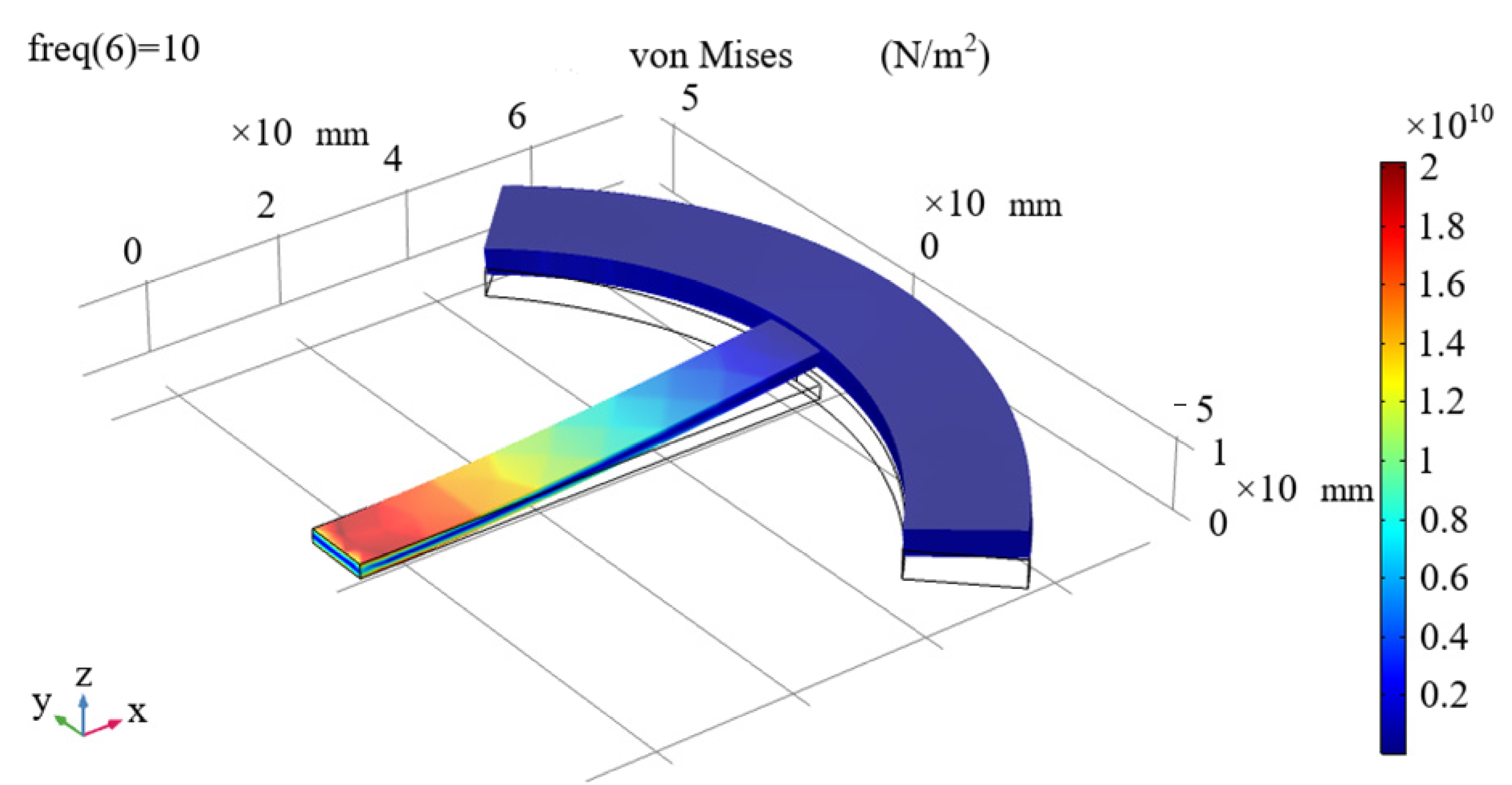
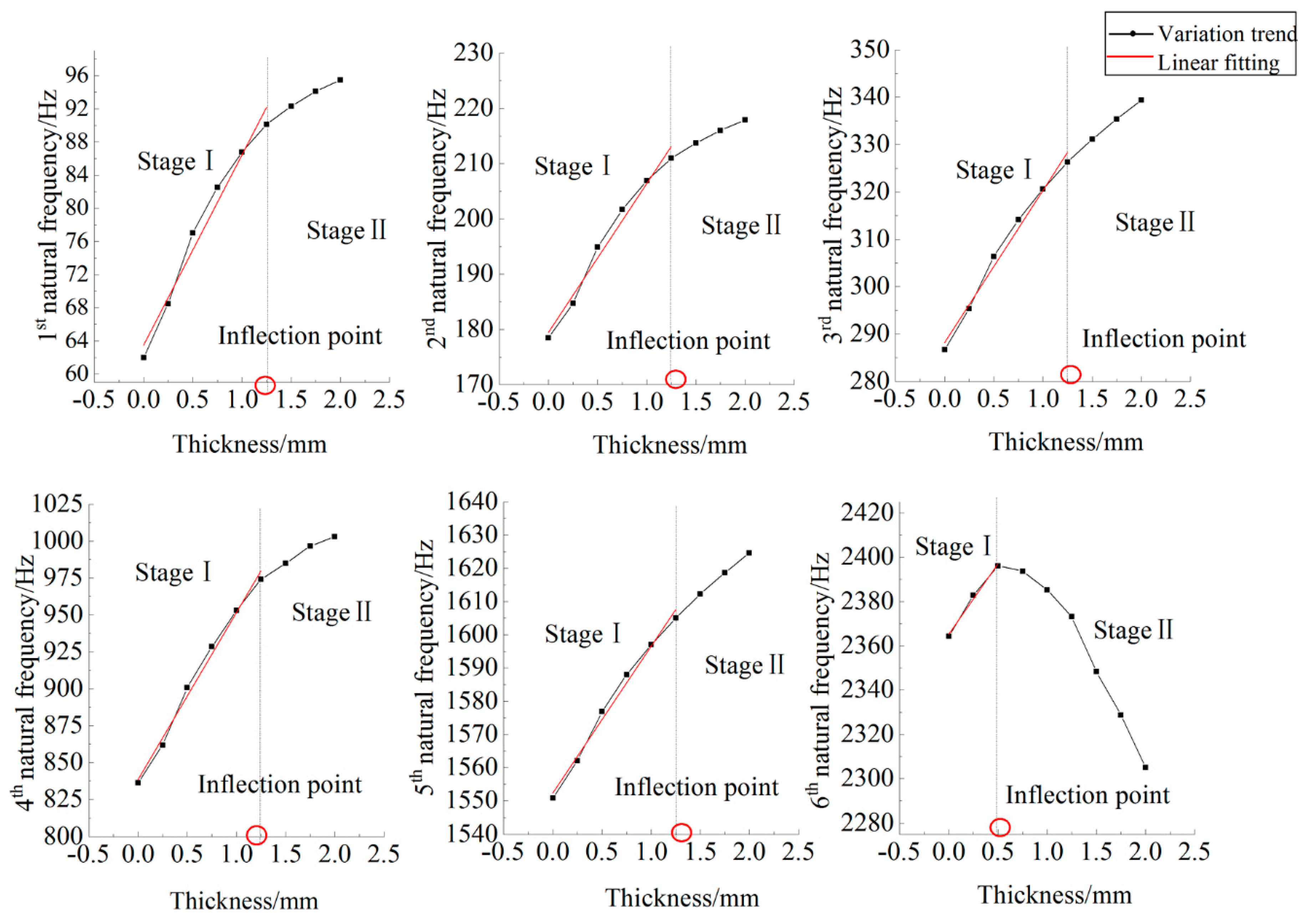
5.3.1. Natural Frequency Variation Analysis

Since the energy generating performance of the proposed device is related to the vibration produced in the actual working process [33,34]. The natural frequency of each order of the piezoelectric cantilever beam could be obtained through modal analysis. Natural frequency variation analysis is conducive to select an appropriate working model for the energy harvesting device and avoiding harmful mode [35]. Meanwhile, research on the variation trend of the natural frequency of the piezoelectric cantilever beam with the thickness of the piezoelectric patches could also provide some reference for the design and selection of the piezoelectric patches. The natural frequency variation analysis is conducted by employing COMSOL Multiphysics computer simulation.
The piezoelectric coupling model of beryllium copper substrate and PZT-5A piezoelectric plate was established by COMSOL Multiphysics software. The design parameters are shown in Table 3. Within the thickness range of 0.25–2 mm with the piezoelectric plate, eight groups of gradient simulation experiments were conducted with a thickness increment of 0.25 mm. At the same time, the piezoelectric plate thickness was set to be zero 0 (non-adherent piezoelectric patches) in the control group. The characteristic frequency was investigated. Moreover, the simulation results show that the excitation frequency (drill pipe vibration frequency) with 10 Hz is smaller than the first-order natural frequencies. Thus, the excitation response could be the largest for the first-order modal. The response becomes weaker with the increase of modes order. The first three to fifth-order frequencies are selected in most studies. However, the energy harvest device is applied in complex underground working conditions. The external vibration frequency is high in certain conditions when the drilling trip occurs. Thus, the first six order frequencies are selected in our work. The trend of the first six order natural frequencies of the piezoelectric coupling model varies along with the thickness of the piezoelectric patches is shown in Figure 6.
As Figure 6 infers, the variation trend of the first six order natural frequencies of the piezoelectric cantilever beam along with the increase of the piezoelectric plate thickness could be basically divided into two periods, namely the rapid growth stage and the constancy or decline period.
Rapid growth stage. In the initial stage, there is a positive correlation between the natural frequency of the piezoelectric cantilever and piezoelectric thickness. The natural frequency of the piezoelectric cantilever increases rapidly with the increase of the piezoelectric thickness until the thickness reaches an inflection point (which is marked with a red circle in Figure 6). The inflection points for the natural frequencies in Figure 6 differ. To be specific, the inflection points are 1.25, 1.25, 1.25, 1.25, 1.25 and 0.5, respectively.
Constancy or decline period. When the piezoelectric plate thickness reaches the inflection point, the natural frequency of the piezoelectric cantilever beam tends to be constancy or decline slowly with the increase of the piezoelectric plate thickness. There is also a decreasing trend of the natural frequency with the increase of thickness in some other orders.
The piezoelectric coupling model before and after the inflection point thickness is also analyzed. For the stage of rapid growth, the piezoelectric cantilever beam is in a good working state. The device mainly modified the piezoelectric cantilever beam structure to harvest the longitudinal vibration energy. The thickness of the piezoelectric plate will affect the power generation performance. When the externally applied load reaches the natural frequencies of each order, resonance occurs, resulting in the largest deformation and the largest power generation. Thus, the variation law of the natural frequency with thickness can be obtained by fitting the scatter points in Figure 6. The linear fitting equation of the natural frequency–thickness of each order in the working state could be obtained by fitting the scatter points, as shown in Table 4. These fitting equations could serve as a reference for optimization design, and the appropriate piezoelectric thickness could be selected according to the natural frequency requirements.
Stress on the piezoelectric plate decreases significantly after its thickness value reaches the inflection point. In the stable or descending stage, the thickness value of the piezoelectric plate becomes large. In this situation, the vibration of the cantilever beam is unable to force the piezoelectric plate to produce enough deformation. Moreover, the motion mode essentially changes to the vibration of the cantilever beam, with the two ends of the piezoelectric plate as the fixed constraints. As a result, the increase of the natural frequency becomes slow, and an inflection point appears in the trend graph. Stress on the piezoelectric plate is too small to generate enough electric charge after its thickness reaches an inflection point; the generator module of the designed energy harvesting device could not work normally. Therefore, the thickness of the piezoelectric plate should not exceed the inflection point in practical design.
It is obvious from Figure 6 that the first-order natural frequency is distributed between 60 and 100 Hz, slightly higher than the peak longitudinal vibration frequency of the drill pipe in the drilling process (which is in the range of 50–65 Hz) [32]. The first-order mode of vibration is an ideal working mode while drilling. The excitation response could be the largest for the first-order modal. Compared to the first three order modes of vibration, the natural frequency of the fourth to sixth-order increases significantly. Excessively high vibration frequency in such a working environment would cause damage to the piezoelectric strain gauge to a certain extent; thus, it should be avoided as far as possible.

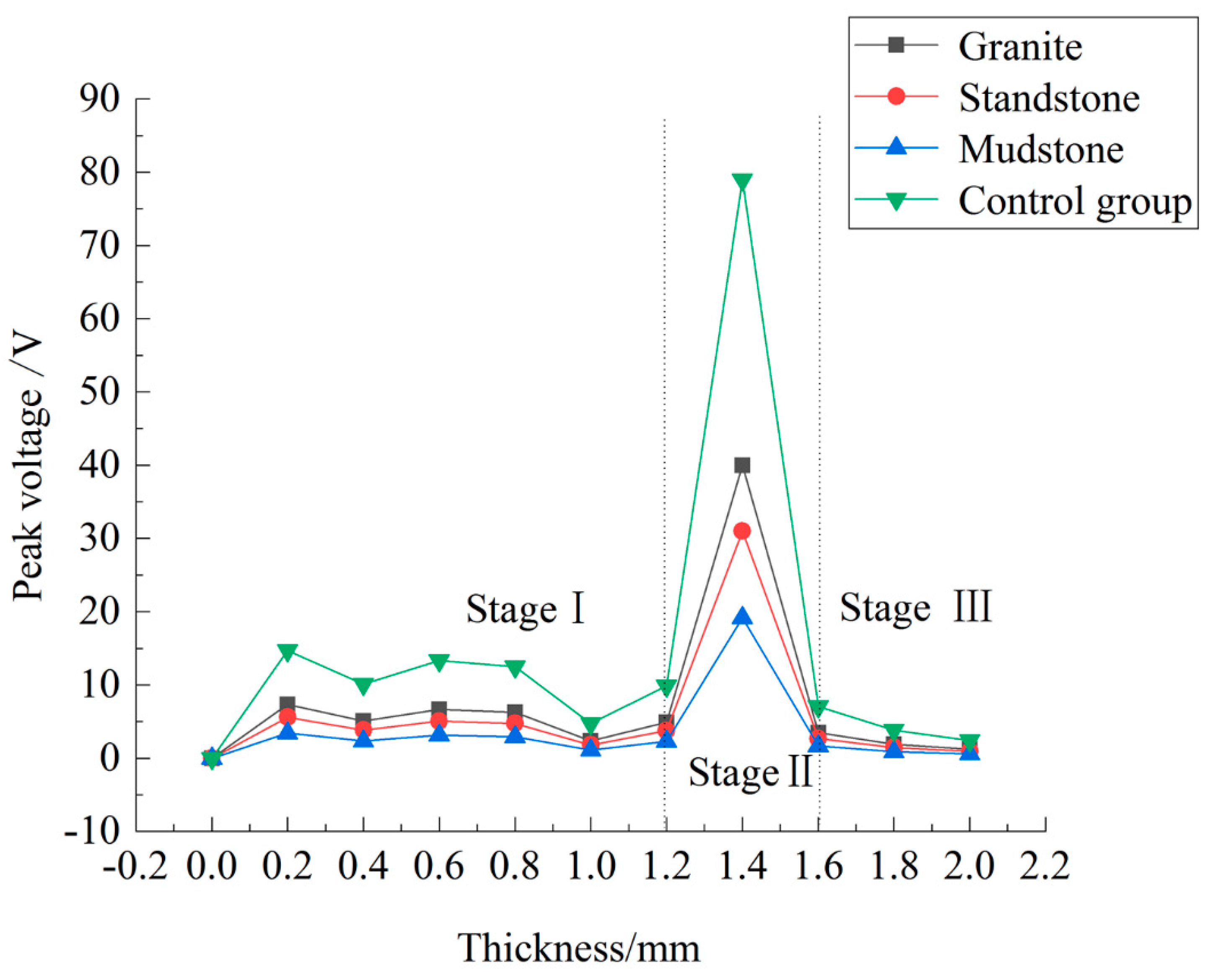
5.3.2. Peak Voltage and Energy Generation Performance Analysis

The hardness of the formation encountered by the bit would be different as the drilling progresses. Therefore, the acceleration of longitudinal vibration of the drill pipe is different due to the difference in strata hardness. Three common drilling rock formations, i.e., mudstone layer, sandstone layer and granite layer, are taken into consideration to investigate energy generation performance in this paper. Vibration loads with accelerations of 0.47 m/s2, 0.76 m/s2 and 1 m/s2, respectively, are set to simulate the working conditions of the drill pipe when drilling in these three formations. Moreover, the vibration load with the acceleration of 2 m/s2 is conducted as the control group.
The COMSOL Multiphysics software was employed to conduct multifield coupling analysis of the piezoelectric device module on the basis of the original solid mechanics module. The upper and lower surfaces of the piezoelectric patches were, respectively, arranged as grounding and terminal. The damping type was set to be an isotropic loss factor. Moreover, the external circuit load resistance R L was set to be 10 kΩ. The external circuit load resistance could also be set to be other values. The peak value of the open-circuit voltage will change, but the trend will be the same. It is clear from Section 5.3.1 that the device’s main working mode is the first-order mode, and Figure 5 obviously indicates that the natural frequency is within 100 Hz. Therefore, the collection range was set to be 0–100 Hz, and the collection step length was set to be 10 Hz for multifield coupling analysis in this section. After frequency response analysis was conducted, the trend of the peak voltage of the piezoelectric cantilever beam varies along with different piezoelectric patches thickness could be gained, and it is shown in Figure 7.
Figure 7 indicates that the generated peak voltage variation trend roughly shows three segments along with the increase of the piezoelectric plate thickness. The first segment is the region that thickness of the piezoelectric plate is within a range of 0–1.2 mm. In this region, the peak voltage trend and the change of thickness seem to be unrelated. Moreover, the voltage fluctuates around a low-level value. The second segment is the region where the thickness of the piezoelectric plate is within the range of 1.2–1.6 mm. In this section, the peak voltage first surges rapidly with the increase of thickness and follows with a high and a sharp decline until it reaches a low value. Moreover, the last segment is the region that thickness of the piezoelectric plate is within the range of 1.6–2 mm. The peak voltage in this region decreases with the increase of the piezoelectric thickness and finally tends to be stable at a low level. In the discharging process, the piezoelectric plate is regarded as a rectifier diode in the ideal state. Ignoring the tube voltage drop, harmonic effect and internal resistance ripple voltage [22], the electrical equation can be obtained as follows:
C p = ε T s h p
U 0 = 2 I m R L π + 2 ω C p R L
In which ω is the excitation angular frequency, rad/s. C p   stands for the equivalent capacitance, and S is the cross-sectional area of the piezoelectric plate. From the above equations that the open-circuit voltage U 0 is positively correlated with the piezoelectric thickness h p with a constant current I m . However, the piezoelectric plate thickness increase would change the motion mode and causes the current I m to go down. Therefore, the peak voltage does not change monotonously with the thickness of the piezoelectric patches but fluctuates and reaches the extreme value near an equilibrium point. The thickness value of the inflection point at the first-order vibration mode shown in Figure 6 overlaps the thickness range of the curve segments in stage II shown in Figure 7. It could be inferred that the electrical parameters of the piezoelectric cantilever beam reach a balance near the inflection point. The inflection point is also a critical point where the motion mode of the piezoelectric cantilever beam changes. At the inflection point, the energy harvesting device has the best performance.
Figure 7 shows that the open-circuit voltage peak of the piezoelectric cantilever beam is roughly within the range of 15–40 V, which basically meets the supply voltage demand of the downhole measuring instruments. However, from the frequency response analysis results, the peak current of a single arm of the cantilever beam is only 8 mA. In other words, the device’s discharge patterns belong to the “high voltage and low current” discharge. Moreover, peak current is greatly affected by the vibration frequency of the drill pipe, leading to an unstable discharge. Compared with a direct power supply, it is more feasible to collect and store capacitors attached to the inner ring for a downhole environment. In the first-order mode, the power of a single energy-capturing plate is about 2.64 W, which shows an inadequate capacity to supply power separately. However, it could be used as auxiliary equipment for battery pack or turbine generator when multiple energy-capturing plates are configured to increase power generation. Moreover, at present, piezoelectric energy harvesting is still in the exploration and research stage. With the development of materials science and structural optimization in the future, the power generation performance of the device could be greatly improved.

6. Conclusions

A while-drilling energy harvesting device was designed to serve as a continuous power supply for downhole equipment by employing the piezoelectric energy collection approach to the drilling industry. The designed device could not only harvest the longitudinal vibration energy produced in the drilling activity but also undertake drill pipe functions. The traditional piezoelectric cantilever beam structure was adopted to adapt to the limited annular space of a drilling borehole. A built-in through-hole was designed to provide a flow path for the drilling fluid. Thus, the device could transform the mechanical energy of longitudinal vibration into electrical energy without affecting the normal drilling process. COMSOL Multiphysics simulations were conducted to investigate the performance of the designed device by taking characteristics of engineering practice into consideration. Simulation results indicated that its natural frequency was 60–100 Hz, which satisfies the requirement of the actual working condition of the drill pipe vibration. The gained peak voltage with different working environments was about 15–40 V, and the obtained peak current was about eight mA. The energy generation performance analysis indicated that the designed device could be used as auxiliary equipment for the power supply. Further research could be conducted on how to improve the structure to integrate multiple groups of energy exchanging elements to get better power generation performance.

Author Contributions

Z.L. designed the device structure and simulation experiments; T.W. and Z.L. carried out the simulation anlysis; J.Z. wrote the manuscript; B.D. and G.C. provided advice on the writing of abstract and conclusions; B.D., H.T., J.Z., and G.C. made a significant contribution to the revision of manuscript. All authors have read and agreed to the published version of the manuscript.

Funding

This research was funded by The National Key Research and Development Programs of China grant number 2019YFB1504201, 2019YFB1504203, and 2019YFB1504204, the National Nature Science Foundation of China under grant NO.51505439, the Research Fund for the Doctoral Program of Higher Education of China under grant no. 2014M562085.

Institutional Review Board Statement

“Not applicable.” for studies not involving humans.

Informed Consent Statement

“Not applicable.” for studies not involving humans.

Data Availability Statement

Data sharing not applicable.

Conflicts of Interest

The authors declare that they have no known competing financial interests or personal relationships that could have appeared to influence the work reported in this paper.

References

  1. Berro, M.J.; Reich, M.; Estevez, M.A.G.; Kruger, U.; Kruger, K.; Jaksch, K.; Giese, R.; Eggemann, K.; Zandi-Nia, A. Robust Unidirectional OFDM-Communication System: Integration in a Drill String and Measurements of the Autarkic System. Oil Gas-Eur. Mag. 2016, 42, 183–189. [Google Scholar]
  2. Zhang, X.S.; Zhang, H.X.; Guo, J.S.; Zhu, L.Z. Auto measurement while drilling mud pulse signal recognition based on deep neural network. J. Pet. Sci. Eng. 2018, 167, 37–43. [Google Scholar] [CrossRef]
  3. Berro, M.J.; Reich, M. Laboratory investigations of a hybrid mud pulse telemetry (HMPT)—A new approach for speeding up the transmitting of MWD/LWD data in deep boreholes. J. Pet. Sci. Eng. 2019, 183, 106374. [Google Scholar] [CrossRef]
  4. Liu, K.M. Model and control method of a downhole electromagnetic transmitter for EM-MWD system. J. Pet. Sci. Eng. 2020, 192, 107210. [Google Scholar] [CrossRef]
  5. Wang, C.L. Bionic design and test of polycrystalline diamond compact bit for hard rock drilling in coal mine. Adv. Mech. Eng. 2020, 12, 1–6. [Google Scholar] [CrossRef]
  6. Huo, A.Q.; He, Y.Y.; Wang, Y.L.; Tang, N.; Cheng, W.B. Study of Downward Communication Receiver in Rotary Steerable Drilling Tool Based on Turbine Generator. In Proceedings of the 29th Chinese Control Conference, Beijing, China, 29–31 July 2010; Chen, J., Ed.; Institute of Electrical and Electronics Engineers: New York, NY, USA, 2010; pp. 4210–4213. [Google Scholar]
  7. Zhang, X.D.; Lu, H.P.; Li, B. 2140. Parameters matching analysis of the stator and rotor for downhole asymmetric turbine generator. J. Vibroeng. 2016, 18, 3512–3523. [Google Scholar] [CrossRef]
  8. Lu, C.H.; Jiang, G.S.; Wang, Z.Q.; Wang, J.H.; Wang, C.L. The development of and experiments on electromagnetic measurement while a drilling system is used for deep exploration. J. Geophys. Eng. 2016, 13, 824–831. [Google Scholar] [CrossRef]
  9. Stojčev, M.K.; Kosanović, M.R.; Golubović, L.R. Power management and energy harvesting techniques for wireless sensor nodes. In Proceedings of the 9th International Conference on Telecommunication in Modern Satellite, Cable, and Broadcasting Services, Niš, Serbia, 7–9 October 2009; pp. 65–72. [Google Scholar]
  10. Liu, S.W.; Fu, M.X.; Jia, H.S.; Li, W.B.; Luo, Y.F. Numerical simulation and analysis of drill rods vibration during roof bolt hole drilling in underground mines. Int. J. Min. Sci. Technol. 2018, 28, 877–884. [Google Scholar] [CrossRef]
  11. Sun, H.Y.; Zhang, A.; Li, H. Experimental study and dynamic characteristics analysis of partially liquid-filled annulus tubes. PLoS ONE 2018, 13, e0209011. [Google Scholar] [CrossRef]
  12. Qin, Y.; Wang, S.; Wei, T.T.; Chen, R. A wide band nonlinear dual piezoelectric cantilever energy harvester coupled by origami. Smart Mater. Struct. 2021, 30, 19. [Google Scholar] [CrossRef]
  13. Deng, J.; Guasch, O.; Zheng, L.; Song, T.T.; Cao, Y.S. Semi-analytical model of an acoustic black hole piezoelectric bimorph cantilever for energy harvesting. J. Sound Vibr. 2021, 494, 17. [Google Scholar] [CrossRef]
  14. Anton, S.R.; Sodano, H.A. A review of power harvesting using piezoelectric materials (2003–2006). Smart Mater. Struct. 2007, 16, R1–R21. [Google Scholar] [CrossRef]
  15. Cui, G.; Pei, S.; Rui, Z.; Dou, B.; Ning, F.; Wang, J. Whole process analysis of geothermal exploitation and power generation from a depleted high-temperature gas reservoir by recycling CO2. Energy 2021, 217, 119340. [Google Scholar] [CrossRef]
  16. Wu, J.G.; Xiao, D.Q.; Zhu, J.G. Potassium-Sodium Niobate Lead-Free Piezoelectric Materials: Past, Present, and Future of Phase Boundaries. Chem. Rev. 2015, 115, 2559–2595. [Google Scholar] [CrossRef]
  17. Gong, J.J.; Ruan, Z.L.; Li, K.; Bian, Y. Study on the Generating Performance of a Novel Piezoelectric Generator with Multilayer Cantilevers. J. Mech. Eng. 2014, 50, 135–140. [Google Scholar] [CrossRef]
  18. Rastegar, J.; Pereira, C.; Nguyen, H.L. Piezoelectric-based power sources for harvesting energy from platforms with low frequency vibration. In Smart Structures and Materials 2006: Industrial and Commercial Applications of Smart Structures Technologies; White, E.V., Davis, L.P., Eds.; Society of Photo Optical: Washington, DC, USA, 2006; Volume 6171. [Google Scholar]
  19. Wang, Q. Research of Vibration Energy Harvesting Based on Piezoelectric Material. Master Thesis, Jiangsu University, Zhenjiang, China, 2008. [Google Scholar]
  20. Varadha, E.; Kumar, S.R.; Jain, X.S.A. Wind-Driven Leaf-Like Thin-Film Piezoelectric Harvester for Low Wind Applications. J. Vib. Eng. Technol. 2021, online. [Google Scholar] [CrossRef]
  21. Subbaramaiah, R.; Al-Jufout, S.A.; Ahmed, A.; Mozumdar, M.M. Design of Vibration-Sourced Piezoelectric Harvester for Battery-Powered Smart Road Sensor Systems. IEEE Sens. J. 2020, 20, 13940–13949. [Google Scholar] [CrossRef]
  22. Erturk, A.; Inman, D.J. An experimentally validated bimorph cantilever model for piezoelectric energy harvesting from base excitations. Smart Mater. Struct. 2009, 18, 025009. [Google Scholar] [CrossRef]
  23. Avvari, P.V.; Yang, Y.W.; Soh, C.K. Long-term fatigue behavior of a cantilever piezoelectric energy harvester. J. Intell. Mater. Syst. Struct. 2017, 28, 1188–1210. [Google Scholar] [CrossRef]
  24. Shu, B.; Ma, B.S.; Lan, H.T. Cuttings Transport Mechanism in a Large-Diameter HDD Borehole. J. Pipeline Syst. Eng. Pract. 2015, 6, 04014017. [Google Scholar] [CrossRef]
  25. Caenn, R.; Chillingar, G.V. Drilling fluids: State of the art. J. Pet. Sci. Eng. 1996, 14, 221–230. [Google Scholar] [CrossRef]
  26. Beeby, S.P.; Tudor, M.J.; White, N.M. Energy harvesting vibration sources for microsystems applications. Meas. Sci. Technol. 2006, 17, R175–R195. [Google Scholar] [CrossRef]
  27. Ottman, G.K.; Hofmann, H.F.; Bhatt, A.C.; Lesieutre, G.A. Adaptive piezoelectric energy harvesting circuit for wireless remote power supply. IEEE Trans. Power Electron. 2002, 17, 669–676. [Google Scholar] [CrossRef] [Green Version]
  28. Chang, C.E.; Tran, V.H.; Wang, J.B.; Fuh, Y.K.; Lin, L.W. Direct-Write Piezoelectric Polymeric Nanogenerator with High Energy Conversion Efficiency. Nano Lett. 2010, 10, 726–731. [Google Scholar] [CrossRef] [PubMed]
  29. Erturk, A.; Inman, D.J. A distributed parameter electromechanical model for cantilevered piezoelectric energy harvesters. J. Vib. Acoust. Trans. ASME 2008, 130, 041002. [Google Scholar] [CrossRef]
  30. Minh, N.Q. Ceramic Fuel-Cells. J. Am. Ceram. Soc. 1993, 76, 563–588. [Google Scholar] [CrossRef]
  31. Hu, J.; Tang, Y.G.; Li, S.X. Vibration test and assessment for an ocean drilling rig derrick: Taking the ZJ50/3150DB drilling rig as an example. Pet. Explor. Dev. 2013, 40, 126–129. [Google Scholar] [CrossRef]
  32. Abdo, J.; Al-Sharji, H. Investigation of vibration effects on friction and axial force transfer of buckled rod constrained in a horizontal cylinder. Tribol. Int. 2015, 92, 317–327. [Google Scholar] [CrossRef]
  33. Song, S.G.; Dalguer, L.A. Importance of 1-point statistics in earthquake source modelling for ground motion simulation. Geophys. J. Int. 2013, 192, 1255–1270. [Google Scholar] [CrossRef] [Green Version]
  34. Roy, N.; Sahu, R.B. Site specific ground motion simulation and seismic response analysis for microzonation of Kolkata. Geomech. Eng. 2012, 4, 1–18. [Google Scholar] [CrossRef]
  35. Hsiao, Y.Y.; Chang, W.C.; Chen, S.L. A mathematic model of thermoelectric module with applications on waste heat recovery from automobile engine. Energy 2010, 35, 1447–1454. [Google Scholar] [CrossRef]
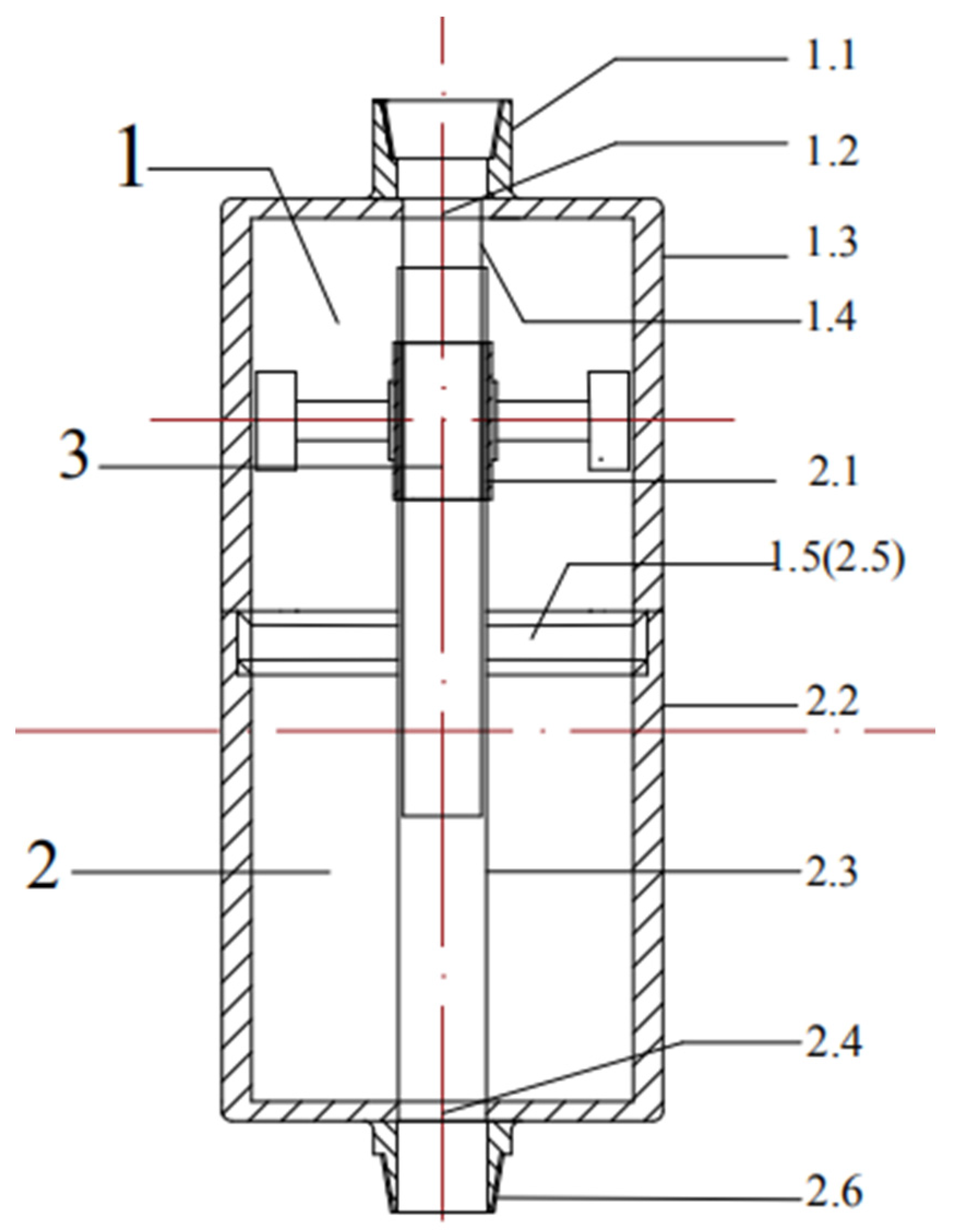
Figure 1. Structure and main components of the while-drilling energy harvesting device. 1.1—upper drill pipe joint, 1.2—through-hole, 1.3—upper shell, 1.4—upper well casing, 1.5—female screw, 2.1—fixing thread, 2.2—lower shell, 2.3—lower well casing, 2.4—through-hole, 2.5—male screw, 2.6—lower drill pipe joint.
Energies 14 01266 g001
Figure 2. Schematic diagram of energy-capturing plate structure; 3.1—inner race, 3.2—capacitor, 3.3—cantilever beam with the piezoelectric element, 3.4—mass block.
Energies 14 01266 g002
Figure 3. Comparison of properties of common high-temperature piezoelectric materials.
Energies 14 01266 g003
Figure 4. The grid model of the cantilever beam.
Energies 14 01266 g004
Figure 5. Stress nephogram of a cantilever beam under 10 Hz frequency disturbance.
Energies 14 01266 g005
Figure 6. Variation trend of the natural frequencies with the thickness of the piezoelectric plates.
Energies 14 01266 g006
Figure 7. Thickness-peak voltage variation trend.
Energies 14 01266 g007
Table 1. Structure and main components of the device.
NO.Structure NameMain Components
1Cylinder upper-end1.1 upper drill pipe joint, 1.2 through-hole, 1.3 upper shell, 1.4 upper well casing, 1.5 female screw
2Cylinder bottom-end2.1 fixing thread, 2.2 lower shell, 2.3 lower well casing, 2.4 through-hole, 2.5 male screw, 2.6 lower drill pipe joint
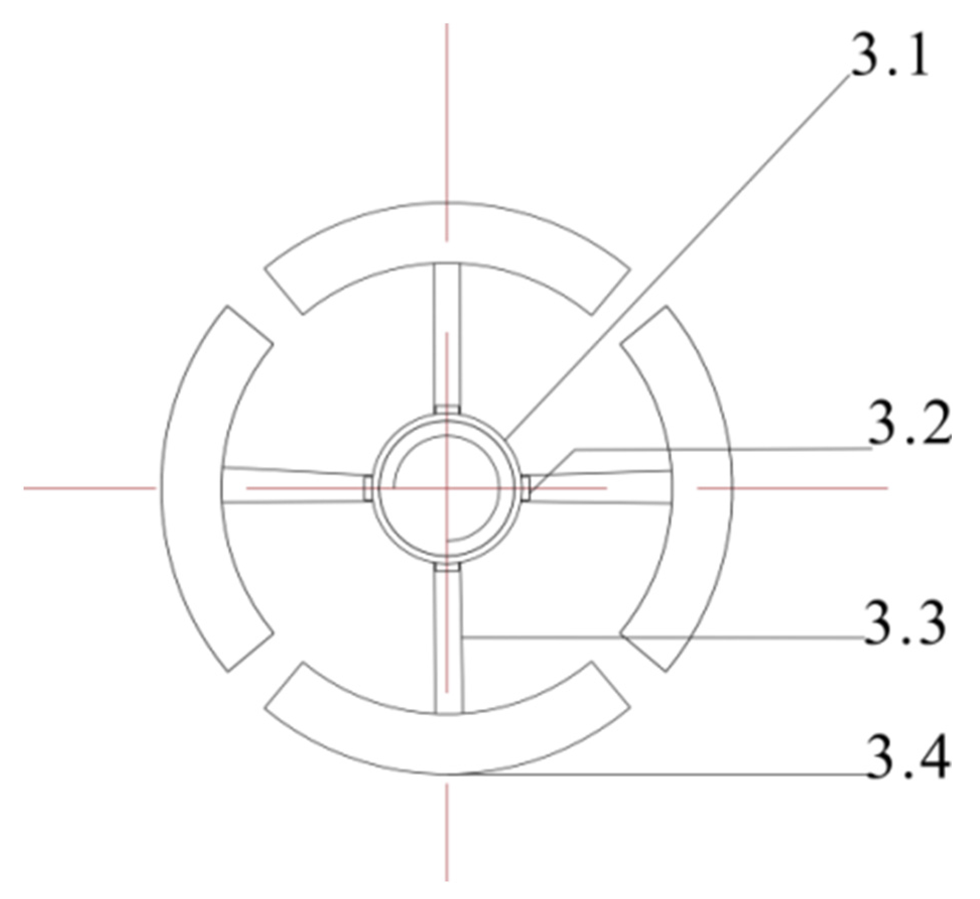
3Energy capturing plate3.1 inner race, 3.2 capacitor, 3.3 cantilever beam with the piezoelectric element, 3.4 mass block
Table 2. Radial dimensions of main components.
Component ParametersOuter Diameter of ShellShell ThicknessOuter Diameter of Well CasingThrough HoleOuter Diameter of Internal RingCantilever BeamMass Block
Size (mm)320.79.85116 (upper well casing)
123 (lower well casing)
112 (upside)
118 (bottom)
1277015
Table 3. Design parameters of the piezoelectric cantilever beam.
Cantilever BeamPiezoelectric Patches
MaterialsBeryllium copperPZT-5A
Length (mm)7024
Width (mm)1010
Thickness (mm)2To be optimized
Young’s modulus (GPa)12859
Poisson’s ratio0.30.272
Density (kg/m3)82507750
Table 4. Linear fitting equations of the natural frequency and thickness of each order.
OrderFirst-OrderSecond OrderThird OrderFourth OrderFifth OrderSix Order
Fitted equationY = 22X + 63Y = 26X + 179Y = 32X + 288Y = 113X + 838Y = 44X + 1552Y = 63X + 2365
Publisher’s Note: MDPI stays neutral with regard to jurisdictional claims in published maps and institutional affiliations.

