Available Transfer Capability Enhancement by FACTS Devices Using Metaheuristic Evolutionary Particle Swarm Optimization (MEEPSO) Technique
Abstract
1. Introduction
1.1. General
1.2. Literature Survey
1.3. Gaps in the Research
- There is an absence of a comparison of intelligent techniques with the conventional methods and power world simulator results. Additionally, there is very least literature available on the use of Power World Simulator, an upcoming power system software, like MATLAB [2,9,28,29,30,31,32,33,34,35,36,37,39,40,41,42,43,44,46,51,52,53,56,57].
1.4. Contributions
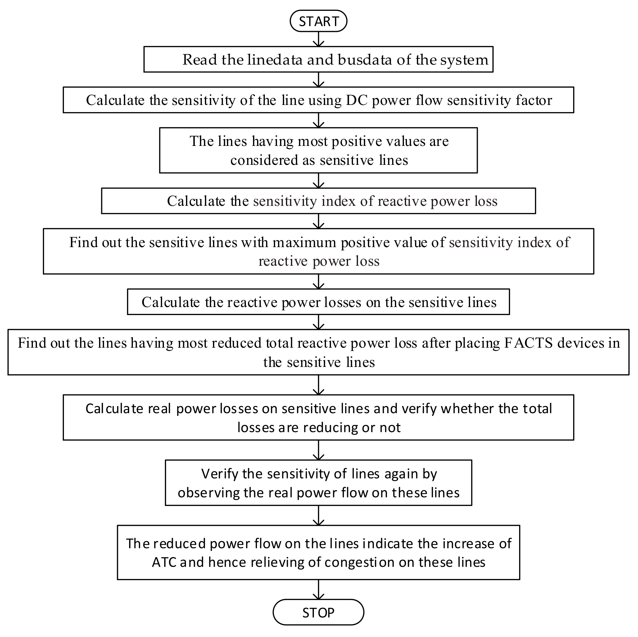
- The placement and location optimization of FACTS device to increase the ATC. An innovative method of determining the optimum location of FACTS devices while using the Sensitivity and Power loss-based Congestion Reduction (SPCR) method has been put forward. The Sensitivity and Power loss-based Congestion Reduction (SPCR) method proposes a technique of finding the optimal location of FACTS devices by adopting the technique of first calculating the sensitivity of all the lines in the considered system and then observing the reduction of reactive and real power losses in the most sensitive lines. The lines having reduced losses are verified again by observing the reduction in real power flows. Because the reduction in power flow by placing FACTS devices in these lines will ensure the increase of ATC in these lines and, hence, there will be less congestion in the system. For this, the two factors viz., DC power flow sensitivity factor, and Reactive Power loss reduction factor is calculated when considering contingencies.
- The calculation of enhanced ATC. A new technique for optimizing the value of ATC is proposed, namely MEEPSO (Metaheuristic Evolutionary Particle Swarm Optimization). It is a metaheuristic technique, as it makes not many or no suppositions about the issue being streamlined and it can look through enormous spaces of up-and-comer arrangements. Additionally, MEEPPSO does not utilize the inclination of the issue being advanced, which implies that it does not necessitate that the improvement issue is differentiable, as is required by exemplary streamlining techniques. MEEPSO technique is used, which gives a higher rate of convergence and helps in optimizing the value of ATC. The acceleration parameters c1 and c2 are elected, both equal to value 2 and inertia weights, is fixed at 1, is at 1.2, compensation is sustained at 50%. The number of iterations is 200 and the number of particles is 50. The calculations are executed beneath MATLAB 2017b milieu.
- Power World Simulator software is used for reckoning ATC besides the results are compared with conventional techniques employing MATLAB software. MATLAB software is a very well-established software, but, with time, pristine software should be advanced. The authors have exploited the Simulator GOS Education 21 version of Power World Simulator software to validate and authenticate the results achieved from MATLAB.
1.5. Organization of Paper
2. Definition of Problem and Modeling
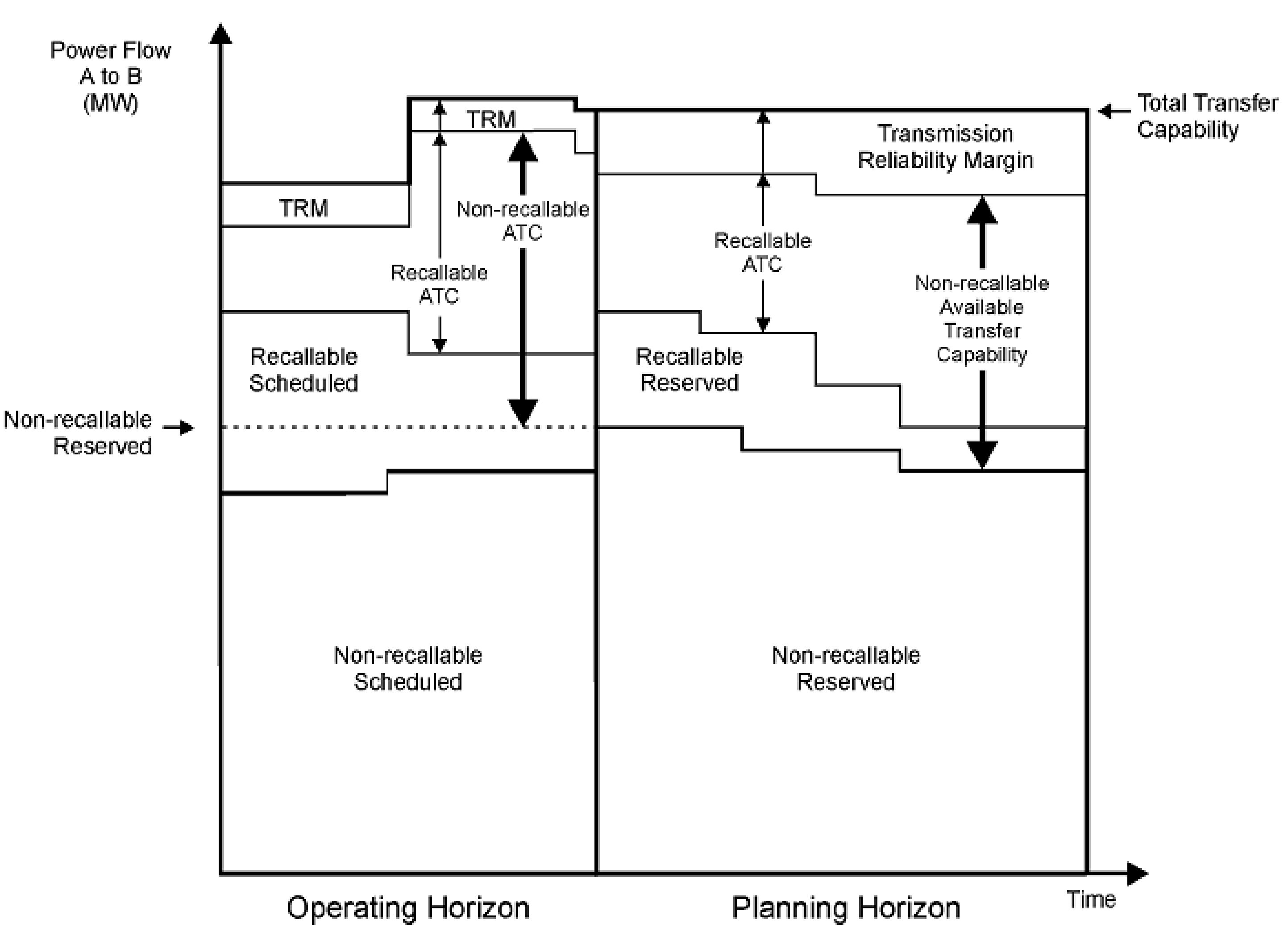
2.1. Importance of Available Transfer Capability
2.2. ATC Determination Using Linear Sensitivity Factors
2.3. Algorithm for Calculation of ATC Using ACPTDF
- Step 1: Calculate the line flow sensitivity factors
- Step 2: Consider an n-node system having as PV buses and as PQ buses.
- Step 3: Bus 1 is the slack bus. Change in flow for an arbitrary line can be evaluated by sensitivity analysis, as follows:
- Step 4: Transacted Power is between bus to bus :
- Step 5: By the N-R Load Flow:
- Step 6: ATC can be calculated, as given below:
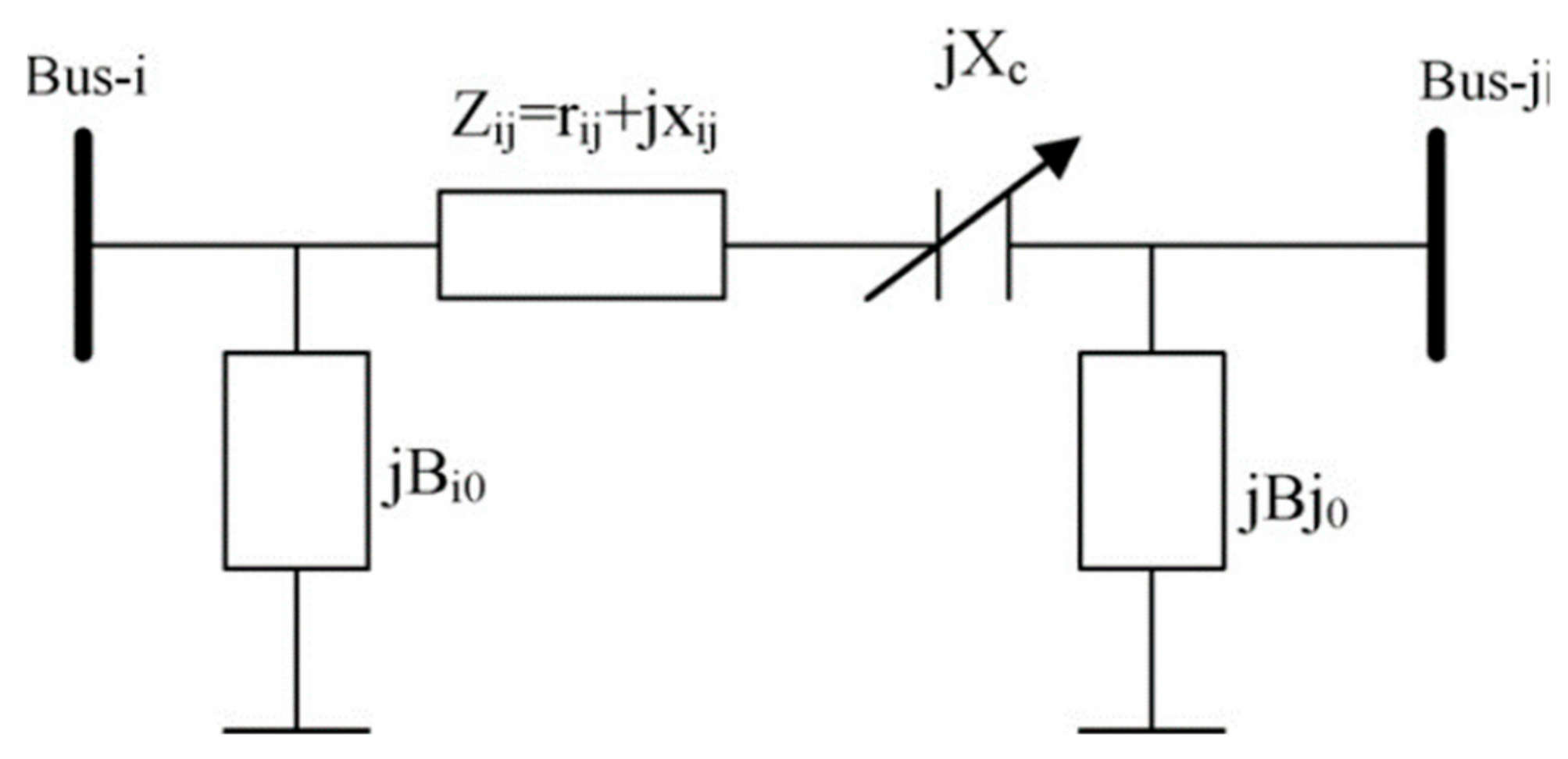
2.4. Use of Flexible Alternating Current Transmission Systems (FACTS)
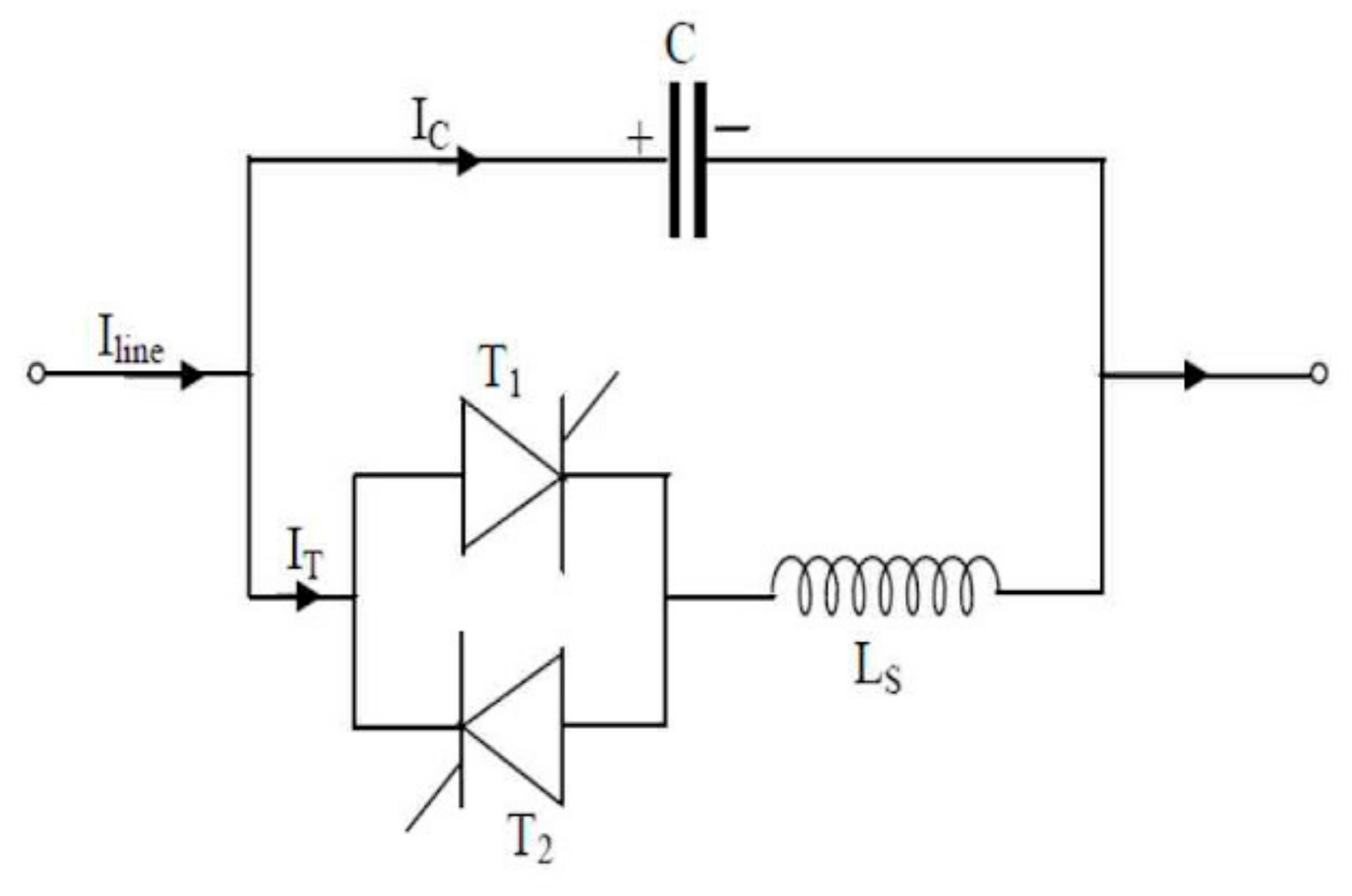
2.5. Thyristor Controlled Series Compensator (TCSC)
2.6. Optimal Location of FACTS Device Using Sensitivity and Power Loss Based Congestion Reduction (SPCR) Method
2.6.1. DC Power Flow Sensitivity Factor Method
2.6.2. Reactive Power Loss Reduction Method
2.6.3. Criteria for Finding the Location of TCSC:
- (a)
- Firstly, for the DC power flow sensitivity factor method, the TCSC device should be located on a line comprising the highest positive DC power flow sensitivity factor, .
- (b)
- Secondly, for the reactive power loss reduction method, the TCSC device should be located on a line that comprises the highest positive reactive power loss sensitivity index, .
2.7. Metaheuristic Evolutionary Particle Swarm Optimization (MEEPSO)
2.7.1. Building of Algorithm
- Step 1: for each particle initialize the position of a particle with a uniformly distributed random vector.
- Step 2: initialize the best-acknowledged position of the particle to its initial position, .
- Step 3: if , then update the swarm’s best-known position, .
- Step 4: initialize the velocity of the particle.while a termination criterion is not met.
- Step 5: for each particle and for each dimension , pick random numbers .
- Step 6: update the velocity of the particle,
- Step 7: update the position of the particle.
- Step 8: if , then update the best-known position of the particle
- Step 9: if , then update the swarm’s best-acknowledged position.
2.7.2. Parameter Choice
- the previous velocity;
- the distance from the position where the particle attained its greatest fitness (personal best, ); and,
- the distance from the particle that accomplished the best fitness among all of the particles (global best, ).
2.8. Power World Simulator (PWS):
3. Results and Discussion
3.1. Placement and Location Optimization of FACTS Device to Increase the ATC
- calculation of values of DC power flow sensitivity factor;
- evaluation of values of reactive power loss sensitivity index and reactive power losses by placing TCSC;
- comparison of total reactive power losses plus real power losses on sensitive lines;
- judgement of total real power losses after placing TCSC on sensitive lines;
- assessment of real power flows besides reactive and real power losses at different locations of TCSC;
- appraisal of total real power losses after placing TCSC on sensitive lines; and,
- comparison of real power flows at different locations of TCSC.
3.1.1. Case 1: 6 Bus System
3.1.2. Case 2: 30 Bus System
3.2. Calculation of Enhanced ATC
- Definition of input parameters in the MEEPSO and initialization of velocity.
- Setting the maximum limit of TCSC compensation and velocity.
- Calculation of ATC.
- Calculation of fitness function and objective function.
- Calculation of particle best position and global best position.
3.2.1. Case 1: 6 Bus System
3.2.2. Case 2: 30 Bus System
4. Conclusions
5. Future Scope
Author Contributions
Funding
Institutional Review Board Statement
Informed Consent Statement
Data Availability Statement
Conflicts of Interest
Nomenclature
| Abbreviation | Full Form |
| ATC | Available Transfer Capability |
| FACTS | Flexible A.C. Transmission Systems |
| SPCR | Sensitivity and Power loss-based Congestion reduction method |
| MEEPSO | Metaheuristic Evolutionary Particle Swarm Optimization |
| TCSC | Thyristor Controlled Series Compensator |
| TTC | Total Transfer Capability |
| TRM | Transmission Reliability Margin |
| CBM | Capacity Benefit Margin |
| ETC | Existing Transmission Commitment |
| ACPTDF | AC Power Transfer Distribution Factor |
| NATC | Non-recallable ATC |
| RATC | Recallable ATC |
| TCSC reactance | |
| AC Power Transfer Distribution Factor for the line between buses i and j when a transaction is taking place between buses m and n | |
| Available Transfer Capability between buses m and n | |
| DCPTDF | DC Power Transfer Distribution Factor |
| complex power flowing between bus i and j | |
Real complex power flowing between bus i and j | |
Imaginary complex power flowing between bus i and j | |
| the voltage at the bus | |
| the current flowing between buses i and j | |
| change in real power | |
| incremental change in real power concerning the change in angle | |
| change in voltage angle | |
| Mismatch vector of change in power at bus m | |
| Mismatch vector of change in power at bus n | |
| Transacted power | |
| Full Jacobian in polar coordinates | |
| The maximum thermal limit of the line ij | |
| The minimum thermal limit of the line ij | |
| Maximum transfer limit values for each line in the system | |
| PTDF | Power Transfer Distribution Factor |
References
- Kumar, A. Available Transfer Capability Determination and Congestion Management in Competitive Electricity Markets; Indian Institute of Technology: Kanpur, India, 2003. [Google Scholar]
- Mohammed, O.O.; Mustafa, M.W.; Mohammed, D.S.S.; Otuoze, A.O. Available transfer capability calculation methods: A comprehensive review. Int. Trans. Electr. Energy Syst. 2019, 29. [Google Scholar] [CrossRef]
- Rama Susmitha, K.; Rao, G.S. Determination of ATC by using DCPTDF and ACPTDF methods. Int. J. Appl. Eng. Res. 2017, 12, 339–344. [Google Scholar]
- Grijalva, S.; Sauer, P.W.; Weber, J.D. Enhancement of linear ATC calculations by the incorporation of reactive power flows. IEEE Trans. Power Syst. 2003, 18, 619–624. [Google Scholar] [CrossRef]
- Dobson, I.; Greene, S.; Rajaraman, R.; DeMarco, C.L.; Alvarado, F.L.; Zimmerman, R. Electric Power Transfer Capability: Concepts, Applications, Sensitivity, Uncertainty; PSERC: Phillips Hall Ithaca, NY, USA, 2001. [Google Scholar]
- Hojabri, M.; Hizam, H.; Mariun, N.; Abdullah, S.M. Comparative analysis of ATC probabilistic methods. J. Am. Sci. 2010, 6, 4–7. [Google Scholar]
- Albatsh, F.M.; Mekhilef, S.; Ahmad, S.; Mokhlis, H.; Hassan, M.A. Enhancing power transfer capability through flexible AC transmission system devices: A review. Front. Inf. Technol. Electron. Eng. 2015, 16, 658–678. [Google Scholar] [CrossRef]
- Magaji, N.; Mustafa, M.W.; Muda, Z.B. Determination of best location of UPFC device for damping oscillation. Eur. J. Sci. Res. 2010, 41, 203–211. [Google Scholar]
- Hassan, M.O.; Cheng, S.J.; Zakaria, Z.A. Staedy state modeling of static synchronous compensator and thyristor control series compensator for power flow analysis. Inf. Technol. J. 2009, 8, 347–353. [Google Scholar] [CrossRef]
- Ghawghawe, N.D.; Thakre, K.L. Computation of TCSC reactance and suggesting criterion of its location for ATC improvement. Electr. Power Energy Syst. 2009, 31, 86–93. [Google Scholar] [CrossRef]
- Rashidinejad, M.; Farahmand, H.; Fotuhi-firuzabad, M.; Gharaveisi, A.A. ATC enhancement using TCSC via artificial intelligent techniques. Electr. Power Syst. Res. 2008, 78, 11–20. [Google Scholar] [CrossRef]
- Gaur, D.; Mathew, L. Optimal placement of FACTS devices using optimization techniques: A review. IOP Conf. Ser. Mater. Sci. Eng. 2018, 331. [Google Scholar] [CrossRef]
- Huang, G.M.; Yan, P. TCSC and SVC as Re-dispatch tools for congestion management and TTC improvement. In Proceedings of the 2002 IEEE Power Engineering Society Winter Meeting, New York, NY, USA, 27–31 January 2002; Volume 1, pp. 660–665. [Google Scholar]
- Pankajam, T.P.; Srinivasa, R.J.; Amarnath, J. ATC enhancement with FACTS devices considering reactive power flows using PTDF. Int. J. Electr. Comput. Eng. 2013, 3, 741–750. [Google Scholar] [CrossRef]
- Ou, Y.; Singh, C. Improvement of total transfer capability using TCSC and SVC. Proc. IEEE Power Eng. Soc. Transm. Distrib. Conf. 2001, 2, 944–948. [Google Scholar] [CrossRef]
- Yadav, N.K. Implementation of FACTS device for enhancement of ATC using PTDF. Int. J. Comput. Electr. Eng. 2011, 3, 343–348. [Google Scholar] [CrossRef]
- Schnurr, N.; Wellssow, W.H. Determination and enhancement of the available transfer capability in FACTS. 2001 IEEE Porto Power Tech Proc. 2001, 4, 34–39. [Google Scholar] [CrossRef]
- Gupta, S.K.; Singh, M.; Sharma, H.D. Enhancement of ATC using UPFC under deregulated environment. J. Power Electron. Power Syst. 2016, 6, 66–72. [Google Scholar]
- Alam, A.; Abido, M.A. Parameter optimization of shunt FACTS controllers for power system transient stability improvement. In Proceedings of the 2007 IEEE Lausanne Power Tech, Lausanne, Switzerland, 1–5 July 2007; pp. 1–6. [Google Scholar]
- Nireekshana, T.; Rao, G.K.; Raju, S.S. Available transfer capability enhancement with FACTS using Cat Swarm Optimization. Ain Shams Eng. J. 2016, 7, 159–167. [Google Scholar] [CrossRef]
- Luo, X.; Patton, A.D.; Singh, C. Real power transfer capability calculations using multi-layer feed-forward neural networks. IEEE Trans. Power Syst. 2000, 15, 903–908. [Google Scholar] [CrossRef]
- Pandey, S.N.; Pandey, N.K.; Tapaswi, S.; Srivastava, L. Neural network-based approach for ATC estimation using distributed computing. IEEE Trans. Power Syst. 2010, 25, 1291–1300. [Google Scholar] [CrossRef]
- Jain, T.; Singh, S.N.; Srivastava, S.C. Fast static available transfer capability determination using radial basis function neural network. Appl. Soft Comput. J. 2011, 11, 2756–2764. [Google Scholar] [CrossRef]
- Zhang, Q.; Benveniste, A. Wavelet networks. IEEE Trans. Neural Netw. 1992, 3, 889–898. [Google Scholar] [CrossRef]
- Zhang, J.; Walter, G.G.; Miao, Y.; Ngai, W.; Lee, W. Wavelet neural networks for function learning. IEEE Trans. Signal Process. 1995, 43, 1485–1497. [Google Scholar] [CrossRef]
- Billings, S.A.; Wei, H. A new class of wavelet networks for nonlinear system identification. IEEE Trans. Neural Netw. 2005, 16, 862–874. [Google Scholar] [CrossRef]
- Ma, X.W. Overview and literature survey of fuzzy set theory in power systems. IEEE Trans. Power Syst. 1995, 10, 1676–1690. [Google Scholar]
- Jang, J.-S.R.; Sun, C.-T.; Mizutani, E. Neuro-Fuzzy and Soft Computing; a Computational Approach to Learning and Machine Intelligence, 6th ed.; Prentice-Hall: Upper Saddle River, NJ, USA, 1997. [Google Scholar]
- Zimmermann, H.J. Fuzzy programming and linear programming with several objective functions. Fuzzy Sets Syst. 1978, 1, 45–55. [Google Scholar] [CrossRef]
- Miranda, V.; Saraiva, J.T. Fuzzy modelling of power system optimal load flow. IEEE Trans. Power Syst. 1992, 7, 843–849. [Google Scholar] [CrossRef]
- Ramesh, V.C.; Li, X. A fuzzy multiobjective approach to contingency constrained OPF. IEEE Trans. Power Syst. 1997, 12, 1348–1354. [Google Scholar] [CrossRef]
- Khairuddin, A.B.; Ahmed, S.S.; Mustafa, M.W.; Zin, A.A.M.; Ahmad, H. A novel method for ATC computations in a large-scale power system. IEEE Trans. Power Syst. 2004, 19, 1150–1158. [Google Scholar] [CrossRef]
- Kim, S.; Kim, M.K.; Park, J. Consideration of multiple uncertainties for evaluation of available transfer capability using fuzzy continuation power flow. Electr. Power Energy Syst. 2008, 30, 581–593. [Google Scholar] [CrossRef]
- Hahn, T.K.; Kim, M.K.; Hur, D.; Park, J.; Yoon, Y.T. Evaluation of available transfer capability using fuzzy multi-objective contingency-constrained optimal power flow. Electr. Power Syst. Res. 2008, 78, 873–882. [Google Scholar] [CrossRef]
- Lai, L.L.; Ma, J.T.; Yokoyama, R.; Zhao, M. Improved genetic algorithms for optimal power flow under both normal and contingent operation states. Electr. Power Energy Syst. 1997, 19, 287–292. [Google Scholar] [CrossRef]
- Paranjothi, S.R.; Anburaja, K. Optimal power flow using refined genetic algorithm. Electr. Power Compon. Syst. 2002, 30, 1055–1063. [Google Scholar] [CrossRef]
- Devaraj, D.; Yegnanarayana, B. Genetic-algorithm-based optimal power flow for security enhancement. IEE Proc.-Gener. Transm. Distrib. 2005, 152, 899–905. [Google Scholar] [CrossRef]
- Bakirtzis, A.G.; Biskas, P.N.; Zoumas, C.E.; Petridis, V. Optimal power flow by enhanced genetic algorithm. IEEE Trans. Power Syst. 2002, 17, 229–236. [Google Scholar] [CrossRef]
- Yuryevich, J.; Wong, K.P. Evolutionary programming based optimal power flow algorithm. IEEE Trans. Power Syst. 1999, 14, 1245–1250. [Google Scholar] [CrossRef]
- Gan, D.; Thomas, R.J.; Zimmerman, R.D. Stability-constrained optimal power flow. IEEE Trans. Power Syst. 2000, 15, 535–540. [Google Scholar] [CrossRef]
- Chen, L.; Tada, Y.; Okamoto, H.; Tanabe, R.; Ono, A. Optimal operation solutions of power systems with transient stability constraints. IEEE Trans. Circuits Syst. I Fundam. Theory Appl. 2001, 48, 327–338. [Google Scholar] [CrossRef]
- Richter, C.W.; Sheble, G.B. Genetic algorithm evolution of utility bidding strategies for the competitive marketplace. IEEE Trans. Power Syst. 1998, 13, 256–261. [Google Scholar] [CrossRef]
- Richter, C.W.; Sheble, G.B.; Ashlock, D. Comprehensive bidding strategies with genetic programming/finite state automata. IEEE Trans. Power Syst. 1999, 14, 1207–1212. [Google Scholar] [CrossRef]
- Gountis, V.P.; Bakirtzis, A.G. Bidding strategies for electricity producers in a competitive electricity marketplace. IEEE Trans. Power Syst. 2004, 19, 356–365. [Google Scholar] [CrossRef]
- Othman, M.M.; Mohamed, A.; Hussain, A. Available transfer capability assessment using evolutionary programming based capacity benefit margin. Int. J. Electr. Power Energy Syst. 2006, 28, 166–176. [Google Scholar] [CrossRef]
- Abido, M.A. Optimal power flow using particle swarm optimization. Electr. Power Energy Syst. 2002, 24, 563–571. [Google Scholar] [CrossRef]
- Mo, N.; Zou, Z.Y.; Chan, K.W.; Pong, T.Y.G. Transient stability constrained optimal power flow using particle swarm optimisation. IET Gener. Transm. Distrib. 2007, 1, 476–483. [Google Scholar] [CrossRef]
- Yumbla, P.E.O.; Ramirez, J.M.; Coello Coello, C.A. Optimal power flow subject to security constraints solved with a particle swarm optimizer. IEEE Trans. Power Syst. 2008, 23, 33–40. [Google Scholar] [CrossRef]
- Zhao, B.; Guo, C.X.; Cao, Y.J. A multiagent-based particle swarm optimization approach for optimal reactive power dispatch. IEEE Trans. Power Syst. 2005, 20, 1070–1078. [Google Scholar] [CrossRef]
- Clerc, M.; Kennedy, J. The particle swarm—Explosion, stability, and convergence in a multidimensional complex space. IEEE Trans. Evol. Comput. 2002, 6, 58–73. [Google Scholar] [CrossRef]
- Farahmand, H.; Rashidinejad, M.; Gharaveici, A.A.; Shojaee, M. An application of hybrid heuristic approach for ATC enhancement. In Proceedings of the 2006 Large Engineering Systems Conference on Power Engineering, Halifax, NS, Canada, 26–28 July 2006; pp. 125–130. [Google Scholar]
- Karthiga, M.M.; Raja, S.C.; Venkatesh, P. Enhancement of available transfer capability using TCSC devices in deregulated power market. In Proceedings of the International Conference on Innovations in Power and Advanced Computing Technologies [i-PACT2017], Vellore, India, 21–22 April 2017; Volume 17, pp. 1–7. [Google Scholar]
- Farahmand, H.; Masoud, R.; Akbar, G.A. A combinatorial approach of real GA & Fuzzy to ATC enhancement. Turkey J. Electr. Eng. 2007, 1, 77–88. [Google Scholar]
- Esmaili, H.; Ramezani, Y.; Hemmatyar, A.M.A. ATC enhancement using SSSC, a case study of harmony search vs PSO. J. Basic Appl. Sci. Res. 2012, 2, 3416–3425. [Google Scholar]
- Sudheer, T.S.; Kakinada, J.; Ananthapur, J. Optimal location of the facts devices using the sensitivity approach for the enhancement of ATC and voltage profile in deregulated power system. Int. J. Comput. Appl. 2013, 76, 32–38. [Google Scholar]
- Mat, N.; Othman, M.M.; Musirin, I.; Mohamed, A.; Hussain, A. Determination of Available Transfer Capability (ATC) Considering Integral Square Generator Angle (ISGA). In Proceedings of the 2nd WSEAS International Conference on Circuits, Systems, Signal and Telecommunications (CISSTș08), Systems, Acapulco, Mexico, 25–27 January 2008; pp. 126–131. [Google Scholar]
- Ramezani, M.; Member, S.S.; Haghifam, M.; Member, S.S.; Singh, C.; Seifi, H.; Moghaddam, M.P. Determination of capacity benefit margin in multiarea power systems using particle swarm optimization. IEEE Trans. Power Syst. 2009, 24, 631–641. [Google Scholar] [CrossRef]
- Tsai, C.Y.; Lu, C.N. Bootstrap application in ATC estimation. IEEE Power Eng. Rev. 2001, 21, 40–42. [Google Scholar] [CrossRef]
- Shi, Y.; Eberhart, R. A modified particle swarm optimizer. In Proceedings of the IEEE International Conference on Evolutionary Computiation, Anchorage, AK, USA, 20–22 May 1998; pp. 69–73. [Google Scholar]
- Eberhart, R.; Kennedy, J. Particle swarm optimization. Proc. IEEE Int. Conf. Neural Networks 1995, 21, 1942–1948. [Google Scholar] [CrossRef]
- Kennedy, J. Particle swarm: Social adaptation of knowledge. Proc. IEEE Conf. Evol. Comput. ICEC 1997, 303–308. [Google Scholar] [CrossRef]
- Kennedy, J.; Eberhart, R.C. Swarm Intelligence, 1st ed.; Morgan Kaufmann: Burlington, MA, USA, 2001. [Google Scholar]
- Poli, R. An Analysis of Publications on Particle Swarm Optimisation Applications; Department of Computer Science, University of Essex: Colchester, UK, 2017. [Google Scholar]
- Poli, R. Analysis of the publications on the applications of particle swarm optimisation. J. Artif. Evol. Appl. 2008, 2008. [Google Scholar] [CrossRef]
- Bonyadi, R.M.; Michalewicz, Z. Particle swarm optimization for single objective continuous space problems: A review mohammad. Evol. Comput. 2017, 25. [Google Scholar] [CrossRef] [PubMed]


| Line No. | |
|---|---|
| 1 | 0.013 |
| 2 | 0.004 |
| 3 | −0.02 |
| 4 | −0.53 |
| 5 | −0.02 |
| 6 | −0.03 |
| 7 | 0.584 |
| 8 | 0.475 |
| 9 | 0 |
| 10 | −0.02 |
| 11 | 0.416 |
| Line No. | |
|---|---|
| 1 | −0.0006 |
| 2 | −0.1533 |
| 3 | −0.0901 |
| 4 | −0.0007 |
| 5 | −0.2363 |
| 6 | −0.0457 |
| 7 | −0.0762 |
| 8 | −0.0821 |
| 9 | −0.4504 |
| 10 | −0.0005 |
| 11 | 0.0007 |
| Line | Reactive Power Losses without TCSC | Reactive Power Losses with TCSC Placed in Line 1 | Reactive Power Losses with TCSC Placed in Line 4 | Reactive Power Losses with TCSC Placed in Line 7 | Reactive Power Losses with TCSC Placed in Line 8 | Reactive Power Losses with TCSC Placed in Line 10 | Reactive Power Losses with TCSC Placed in Line 11 |
|---|---|---|---|---|---|---|---|
| 1 | −4.058 | −4.115 | −4.061 | −4.050 | −4.052 | −4.058 | −4.051 |
| 2 | −1.167 | −1.234 | −1.168 | −1.164 | −1.169 | −1.162 | −1.176 |
| 3 | −3.680 | −3.741 | −3.667 | −3.707 | −3.717 | −3.686 | −3.755 |
| 4 | −6.587 | −6.588 | −6.588 | −6.585 | −6.588 | −6.587 | −6.588 |
| 5 | 1.365 | 1.405 | 1.369 | 1.355 | 1.350 | 1.365 | 1.337 |
| 6 | −2.530 | −2.513 | −2.520 | −2.553 | −2.567 | −2.531 | −2.603 |
| 7 | −3.833 | −3.823 | −3.807 | −3.924 | −3.827 | −3.836 | −3.760 |
| 8 | −2.586 | −2.573 | −2.603 | −2.582 | −2.651 | −2.584 | −2.690 |
| 9 | 3.225 | 3.226 | 3.197 | 3.096 | 3.183 | 3.227 | 3.398 |
| 10 | −7.752 | −7.751 | −7.750 | −7.756 | −7.760 | −7.753 | −7.768 |
| 11 | −5.820 | −5.820 | −5.820 | −5.819 | −5.830 | −5.818 | −5.851 |
| TCSC Place (Lines) | Total Reactive Power Losses without TCSC | Total Reactive Power Losses with TCSC |
|---|---|---|
| 1 | −33.425 | −33.527 |
| 4 | −33.425 | −33.4214 |
| 7 | −33.425 | −33.690 |
| 8 | −33.425 | −33.627 |
| 10 | −33.425 | −33.4266 |
| 11 | −33.425 | −33.509 |
| Line | Real Power Losses without TCSC | Real power Losses with TCSC Placed at Line 1 | Real Power Losses with TCSC Placed at Line 4 | Real Power Losses with TCSC Placed at Line 7 | Real Power Losses with TCSC Placed at Line 8 | Real Power Losses with TCSC Placed at Line 10 | Real Power Losses with TCSC Placed at Line 11 |
|---|---|---|---|---|---|---|---|
| 1 | 0.176 | 0.158 | 0.1742 | 0.180 | 0.179 | 0.1759 | 0.179 |
| 2 | 0.747 | 0.737 | 0.74698 | 0.748 | 0.747 | 0.74873 | 0.745 |
| 3 | 0.677 | 0.666 | 0.6802 | 0.670 | 0.668 | 0.67483 | 0.659 |
| 4 | 0.031 | 0.031 | 0.03078 | 0.031 | 0.031 | 0.03101 | 0.031 |
| 5 | 1.722 | 1.734 | 1.72399 | 1.717 | 1.714 | 1.72204 | 1.708 |
| 6 | 0.538 | 0.542 | 0.54154 | 0.531 | 0.527 | 0.53768 | 0.516 |
| 7 | 0.506 | 0.508 | 0.51544 | 0.476 | 0.509 | 0.50541 | 0.530 |
| 8 | 1.247 | 1.250 | 1.23884 | 1.249 | 1.218 | 1.24738 | 1.202 |
| 9 | 1.076 | 1.076 | 1.07032 | 1.050 | 1.068 | 1.07633 | 1.110 |
| 10 | 0.016 | 0.016 | 0.01701 | 0.015 | 0.015 | 0.01508 | 0.015 |
| 11 | 0.039 | 0.039 | 0.03937 | 0.042 | 0.037 | 0.03982 | 0.030 |
| TCSC Place (Lines) | Total Real Power Losses without TCSC | Total Real Power Losses with TCSC |
|---|---|---|
| 1 | 6.77575 | 6.75901 |
| 4 | 6.77575 | 6.77867 |
| 7 | 6.77575 | 6.70832 |
| 8 | 6.77575 | 6.71365 |
| 10 | 6.77575 | 6.77421 |
| 11 | 6.77575 | 6.72544 |
| Line | Real Power Flow without TCSC | Real Power flow with TCSC Placed at Line 1 | Real Power flow with TCSC Placed at Line 4 | Real Power flow with TCSC Placed at Line 7 | Real Power flow with TCSC Placed at Line 8 | Real Power flow with TCSC Placed at Line 10 | Real Power flow with TCSC Placed at Line 11 |
|---|---|---|---|---|---|---|---|
| 1 | 12.548 | 11.743 | 12.4813 | 12.619 | 13.882 | 12.5424 | 12.641 |
| 2 | 31.762 | 31.191 | 31.7434 | 31.787 | 32.262 | 31.8514 | 31.785 |
| 3 | 25.635 | 25.239 | 25.7463 | 25.543 | 24.258 | 25.5546 | 25.505 |
| 4 | −2.293 | −2.186 | −1.7645 | −2.601 | 1.5803 | −2.3334 | −2.193 |
| 5 | 43.440 | 44.000 | 43.5348 | 43.345 | 41.543 | 43.5864 | 43.262 |
| 6 | 17.222 | 17.408 | 17.376 | 17.082 | 14.769 | 17.1521 | 16.996 |
| 7 | 23.363 | 23.479 | 23.7377 | 22.82 | 25.135 | 23.3214 | 23.758 |
| 8 | 25.068 | 25.185 | 24.8182 | 25.154 | 19.097 | 25.0268 | 24.691 |
| 9 | 50.077 | 50.068 | 49.6172 | 49.684 | 44.755 | 50.0788 | 50.555 |
| 10 | 2.7340 | 2.7190 | 2.8072 | 2.6650 | 1.416 | 2.6596 | 2.5900 |
| 11 | −1.819 | −1.922 | −1.7298 | −2.026 | 1.671 | −1.7787 | −1.343 |
| Line No. | ||
|---|---|---|
| 1 | −1.7892 | 0.5022 |
| 2 | −0.4472 | 0.3153 |
| 3 | −0.1018 | 0.2506 |
| 4 | −0.3803 | 0.3206 |
| 5 | −0.2001 | 0.0772 |
| 6 | 3.4922 | 0.171 |
| 7 | 6.6495 | −0.2954 |
| 8 | 0.2636 | 0.0777 |
| 9 | 2.1356 | −0.0752 |
| 10 | 2.5852 | 0.0644 |
| 11 | 10.4489 | −0.9943 |
| 12 | 0.5046 | 0.6298 |
| 13 | 0.0695 | −0.0001 |
| 14 | 4.6528 | 0.0000 |
| 15 | 0.4842 | 0.7747 |
| 16 | 0.8399 | 0.0003 |
| 17 | 2.9897 | 0.0854 |
| 18 | 1.0709 | 0.2574 |
| 19 | 7.3753 | 0.3006 |
| 20 | 9.6101 | 0.0563 |
| 21 | 2.0937 | 0.2951 |
| 22 | 2.2205 | 0.1704 |
| 23 | 0.6347 | 0.17 |
| 24 | 2.5254 | 0.1688 |
| 25 | 1.0705 | −0.1648 |
| 26 | 1.223 | −0.2909 |
| 27 | 1.0185 | −0.1837 |
| 28 | 1.2278 | −0.1124 |
| 29 | 1.2848i | −0.2004 |
| 30 | 3.1627i | 0.0613 |
| 31 | 11.1062 | −0.3365 |
| 32 | 1.2400 | 0.0604 |
| 33 | 1.5269 | −0.2700 |
| 34 | 0.7036 | 0.0002 |
| 35 | 0.4730 | −0.2677 |
| 36 | 0.3341 | 0.2869 |
| 37 | 1.0920 | 0.0004 |
| 38 | 0.2544 | 0.0003 |
| 39 | 0.1222 | 0.0000 |
| 40 | 0.1393 | 0.6300 |
| 41 | 0.2663 | 0.2530 |
| Line | Reactive Power Losses without TCSC | Reactive Power Losses with TCSC Placed at Line 11 | Reactive Power Losses with TCSC Placed at Line 12 | Reactive Power Losses with TCSC Placed at Line 15 | Reactive Power Losses with TCSC Placed at Line 31 |
|---|---|---|---|---|---|
| 1 | 11.13451 | 11.12571 | 11.13942 | 11.12366 | 11.1241 |
| 2 | 7.53579 | 7.52316 | 7.50126 | 7.52690 | 7.52638 |
| 4 | 1.50751 | 1.50424 | 1.49965 | 1.50506 | 1.50495 |
| 11 | 1.42692 | 1.35439 | 1.18628 | 1.45551 | 1.46557 |
| 12 | 1.10438 | 1.07069 | 0.87069 | 1.10878 | 1.11779 |
| 15 | −0.0913 | −0.12165 | −0.12085 | −0.12268 | −0.12308 |
| 19 | −0.20679 | −0.20856 | −0.20908 | −0.20852 | −0.20866 |
| 20 | −0.18536 | −0.19069 | −0.19756 | −0.18957 | −0.18869 |
| 31 | −0.19328 | −0.19655 | −0.19768 | −0.19647 | −0.19798 |
| TCSC Place (Lines) | Total Reactive Power Losses without TCSC | Total Reactive Power Losses with TCSC |
|---|---|---|
| 11 | 22.03238 | 21.86074 |
| 12 | 22.03238 | 21.47213 |
| 15 | 22.03238 | 22.00267 |
| 31 | 22.03238 | 22.02039 |
| Line | Real Power Losses without TCSC | Real Power Losses with TCSC Placed in Line 11 | Real Power Losses With TCSC Placed in Line 12 | Real Power Losses with TCSC Placed in Line 15 | Real Power Losses with TCSC Placed in Line 31 |
|---|---|---|---|---|---|
| 1 | 5.41374 | 5.41092 | 5.41531 | 5.41027 | 5.41041 |
| 2 | 2.83736 | 2.83486 | 2.82975 | 2.83571 | 2.83559 |
| 4 | 0.77990 | 0.77914 | 0.77769 | 0.77938 | 0.77935 |
| 11 | 0.00781 | 0.00747 | 0.00667 | 0.00795 | 0.00800 |
| 12 | 0.00235 | 0.00230 | 0.00194 | 0.00236 | 0.00238 |
| 15 | 0.00094 | 0.00072 | 0.00073 | 0.00071 | 0.00071 |
| 19 | 0.00604 | 0.00521 | 0.00467 | 0.00528 | 0.00516 |
| 20 | 0.01188 | 0.01012 | 0.00723 | 0.01062 | 0.01100 |
| 31 | 0.00611 | 0.00523 | 0.00472 | 0.00528 | 0.00461 |
| TCSC Place (Lines) | Total Real Power Losses without TCSC | Total Real Power Losses with TCSC |
|---|---|---|
| 11 | 9.06613 | 9.05597 |
| 12 | 9.06613 | 9.04871 |
| 15 | 9.06613 | 9.05756 |
| 31 | 9.06613 | 9.05721 |
| Line | Real Power flow without TCSC | Real Power Flow with TCSC Placed in Line 11 | Real Power flow with TCSC Placed in Line 12 | Real Power Flow with TCSC Placed in Line 15 | Real Power Flow with TCSC Placed in Line 31 |
|---|---|---|---|---|---|
| 1 | 178.02707 | 177.98063 | 178.05303 | 177.9698 | 177.97217 |
| 2 | 83.70249 | 83.67309 | 83.59858 | 83.68524 | 83.68349 |
| 4 | 77.96646 | 77.96907 | 77.90455 | 77.97841 | 77.97695 |
| 11 | 28.67239 | 28.05487 | 26.51498 | 28.94278 | 29.02952 |
| 12 | 15.86664 | 15.68053 | 14.41164 | 15.91052 | 15.96439 |
| 15 | 10.24171 | 9.02014 | 9.05466 | 8.97577 | 8.95846 |
| 19 | 1.66163 | 1.5503 | 1.45953 | 1.56275 | 1.54264 |
| 20 | 3.8824 | 3.59592 | 3.02208 | 3.6869 | 3.75377 |
| 31 | 2.12521 | 1.97072 | 1.86432 | 1.98284 | 1.84347 |
Publisher’s Note: MDPI stays neutral with regard to jurisdictional claims in published maps and institutional affiliations. |
© 2021 by the authors. Licensee MDPI, Basel, Switzerland. This article is an open access article distributed under the terms and conditions of the Creative Commons Attribution (CC BY) license (http://creativecommons.org/licenses/by/4.0/).
Share and Cite
Gupta, D.; Jain, S.K. Available Transfer Capability Enhancement by FACTS Devices Using Metaheuristic Evolutionary Particle Swarm Optimization (MEEPSO) Technique. Energies 2021, 14, 869. https://doi.org/10.3390/en14040869
Gupta D, Jain SK. Available Transfer Capability Enhancement by FACTS Devices Using Metaheuristic Evolutionary Particle Swarm Optimization (MEEPSO) Technique. Energies. 2021; 14(4):869. https://doi.org/10.3390/en14040869
Chicago/Turabian StyleGupta, Divya, and Sanjay Kumar Jain. 2021. "Available Transfer Capability Enhancement by FACTS Devices Using Metaheuristic Evolutionary Particle Swarm Optimization (MEEPSO) Technique" Energies 14, no. 4: 869. https://doi.org/10.3390/en14040869
APA StyleGupta, D., & Jain, S. K. (2021). Available Transfer Capability Enhancement by FACTS Devices Using Metaheuristic Evolutionary Particle Swarm Optimization (MEEPSO) Technique. Energies, 14(4), 869. https://doi.org/10.3390/en14040869


