1. Introduction
Among the different systems that use renewable energy, wind power generation is highlighted, where wind as the primary energy source is free and renewable. Wind power systems are characterized by being a variable energy source due to the wind speed depending on weather conditions. In addition, wind power systems operate under conditions of variable velocity, maximum extraction of wind energy, minimum losses in the energy conversion process, and comply with the connection standards within a utility grid. Therefore, these operating conditions represent a technological challenge in the design of the control system applied to wind power systems. It is common practice to emulate in a laboratory the wind turbine operation by means of an electric motor that tracks the output velocity from a virtual wind system and thus replaces the turbine. Consequently, using a wind turbine emulator, the infrastructure related to the wind turbine is avoided, such as the wind tunnel and the turbine, among other components needed for the operation of a real wind system.
In this sense, some works regarding wind turbine emulators based on electrical machines have been reported in the specialized literature. In [
1], a four-quadrant dynamometer is used, while the permanent magnet synchronous motor (PMSM) is applied in [
2,
3,
4,
5] and the induction motor is used in [
6,
7,
8]. However, most emulators reported are based on the DC motor due to the flexibility in its operation and simplicity in the design and implementation of its control systems. In [
9], a simple closed loop control based on the hysteresis band is presented. Fuzzy logic control techniques and first-order sliding modes are used in [
10,
11], respectively. Additionally, a classical PI control has been widely used to regulate the DC motor velocity [
12,
13,
14,
15,
16,
17]. This controller has some disadvantages such as high overshoot, sensitivity to the parameter variation, and maintaining a steady-state error. All previous reported controllers use a velocity sensor to solve the problem of velocity tracking, which raises the cost of construction and increases friction losses. In addition, velocity sensors reduce reliability due to the growth in the number of mechanical components.
The main motivation in this work is to emulate the operation of a small-scale wind turbine by means of a DC motor that is driven by a robust velocity controller, does not use a mechanical speed sensor, and does not depend on any motor parameter. For the implementation and validation of the wind turbine emulator, the DC motor is coupled with a dynamometer that configures the electromagnetic torque of an electric generator which is contained in a virtual wind system. Our proposal lays the foundations for a future work to emulate a whole wind system connected to the electricity grid through a DC motor directly coupled to an electric generator, which is controlled to maximize the capture of energy from the wind and connect the power generated to the utility grid. Therefore, the emulation of the wind system avoids including the infrastructure related to the wind turbine, the wind tunnel, and the accessories needed for the operation of a real wind system on a small scale.
The main contribution of this research consists in providing a methodology for the design and physical implementation of a wind turbine emulator through a DC motor coupled with a dynamometer that sets the generator torque from a virtual wind system. When the DC motor tracks the velocity from virtual wind system, it mimics the operation of the wind turbine. The tracking problem is solving through a sensorless robust velocity controller which is synthesized applying the state-feedback linearization technique combined with the super-twisting algorithm to configure a robust closed-loop system in the presence of load torque changes. A robust velocity observer to estimate the motor velocity is designed based on the armature current measuring, so that the velocity controller only uses an armature current sensor to perform its operation.
This article is organized as follows.
Section 2 describes the mechanical model that defines the virtual wind system.
Section 3 presents the design of a robust observer that estimates the motor velocity and that gives the sensorless characteristic to the velocity control system.
Section 4 shows the design process of the velocity controller for tracking the output velocity of a virtual wind system.
Section 5 shows the experimental results that validate the good performance of the emulator. Finally, the conclusions of the work are drawn in
Section 6.
2. Wind System Model
The wind energy is transformed into rotatory mechanical energy when the kinetic energy of the wind collides with the blades of the turbine commonly composed of three blades. The turbine is mechanically coupled to an electric generator through a gearbox whose purpose is to convet the low velocity of the turbine to the high velocity of the generator. The mechanical power developed by the wind turbine is defined by the following equation [
18]:
where
is the wind density of the place;
is the sweep area of the turbine;
is the power coefficient that defines the wind turbine efficiency, and this term is the only one that can vary influenced by a control action; and
is the wind speed raised to the cube. It is important to highlight that the amplification of power due to the increase in wind speed makes the wind power systems very attractive. The turbine torque is calculated by dividing the mechanical power (
1) by the angular velocity of the turbine, resulting in:
The power coefficient
depends on the constructive characteristics of the turbine and it varies according to the tip-speed ratio
, which is defined as the ratio of the tangential speed in the turbine tip by the wind speed, as follows:
where
represents the angular velocity of the turbine. The power coefficient curve can be approximated with the following nonlinear function [
19]:
with
where
is the pitch angle of the turbine blades and the values of constants
–
are related to the unique design of a wind turbine and are generally obtained empirically in laboratory tests. In this proposal, the stall wind turbine parameters
,
,
,
,
,
, and
were taken from Voltolini et al. [
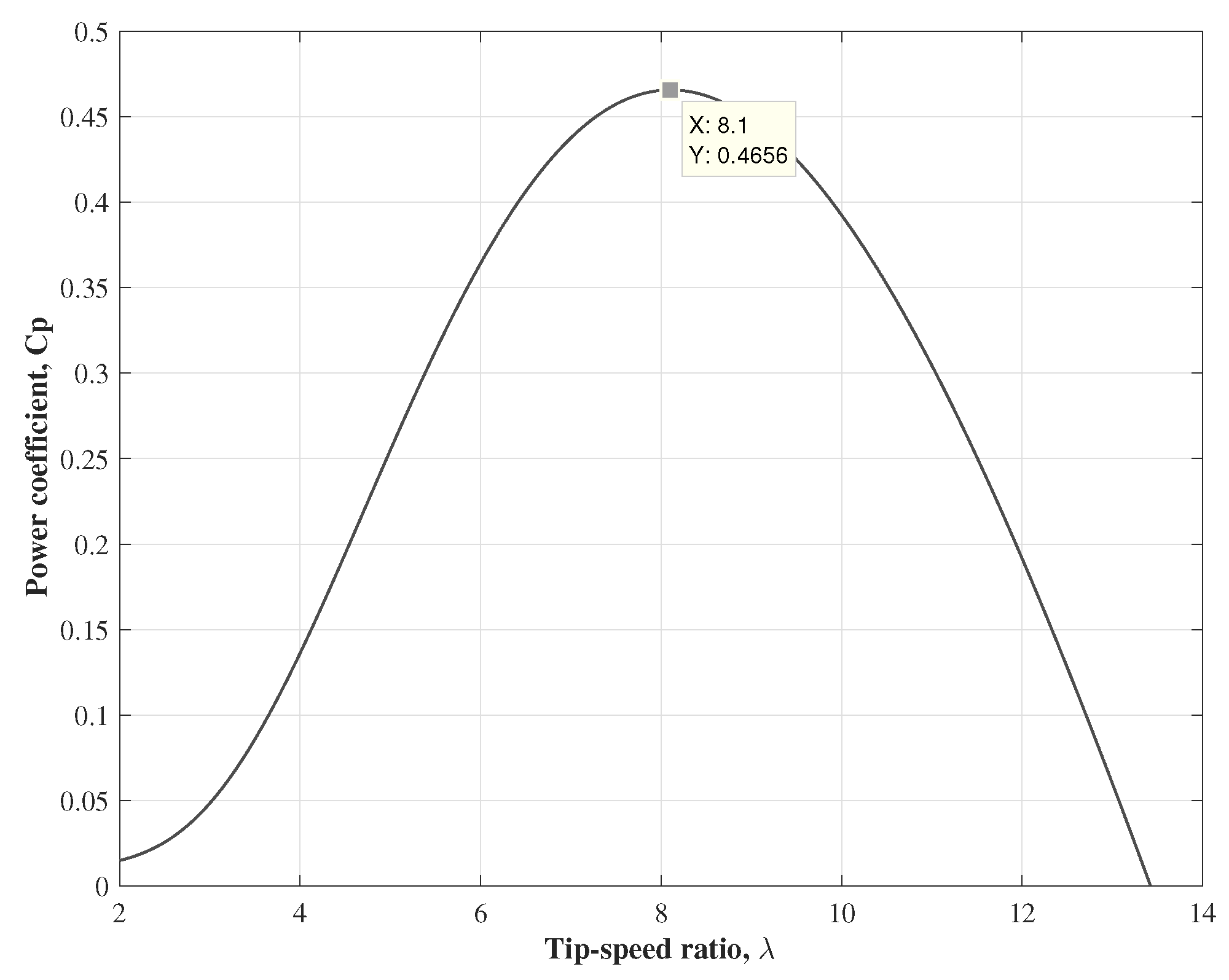
19]. The power coefficient curve is depicted in
Figure 1, where the maximum power coefficient
is
, which is related to the desired tip-speed ratio
of
. The
desired is a constant value, which is obtained when Equation (
4) is maximum
.
On the other hand, the mechanical oscillation equation of the wind system, where the torsional forces of all components coupled in the shaft train are always in balance, can be approximate by the following expression:
where the mechanical parameters are the total inertial moment
and the total frictional coefficient
. Both parameters are referred to the high velocity side of the generator with
and
where
and
are the inertial moment and frictional coefficient of the wind turbine, respectively;
and
are the inertial moment and frictional coefficient of the electric generator;
is the generator angular velocity;
is the mechanical turbine torque;
is the gearbox ratio that couples the wind turbine low velocity with the generator high velocity; and
is the generator torque which can be controlled by tracking of a reference torque.
The common control goal of a wind system consists of maximizing the wind energy capture, which is achieved by maintaining the coefficient power of the turbine power in its maximum value (
1). Then, considering that the desired tip-speed ratio (
) is reached when the coefficient power is maximized, from Equation (
3) the following relation is fulfilled:
Defining the velocity tracking error as
and using (
5), the evaluation of the tracking error derivative is calculated as:
The asymptotic convergence of the velocity tracking error can be established as
, with
[
20]. Then,
where the electric torque reference for the generator can be calculated by solving
in (
8) as:
From (
9), it is easy to see that the electric torque reference (
) used for the generator’s torque controller is a function of the time derivative of wind velocity (
), the turbine torque (
), and the generator velocity (
). On the other hand, when the generator velocity is controlled, the desired velocity (
6) is defined as the velocity reference. Therefore, in this work, a robust observer is proposed to estimate the mechanical velocity of the generator, thus avoiding the use of a velocity sensor in the emulation of the turbine operation.
3. DC Motor Velocity Observer Design
The DC motor is a very versatile electric machine to set different operation characteristics. Using the DC motor as the prime motor, a wide range of velocities can be established simply compared to other electric motors. Then, by modulating the voltage supply to armature winding, the DC motor can work from standstill to nominal velocity and by weakening the field winding velocities can be set above nominal. However, the use of a velocity sensor in closed loop velocity controllers requires wires and signal conditioning, consequently increasing the maintenance requirements. Thus, it is proposed to apply a robust observer to estimate the rotor velocity through the measuring of the armature current [
21]. The observer design is based on the DC motor model, which is a separately excited DC motor with constant magnetizing whose model is [
22]:
where the armature current
and rotor velocity
are the state variables; the mechanical input
is the load torque;
is the control input that corresponds to the voltage supplied to armature winding;
and
are the resistance and inductance of the armature winding, respectively;
and
are the frictional coefficient and inertial moment of the DC motor and the mechanical load together, respectively; and
and
are the machine constants that include the constant field current, both having the same value but different measure units. The proposal of the robust rotor velocity observer has the following form [
21]:
where
and
are the observed velocity and observed armature current, respectively;
is a constant; and
is a discontinuous input with the observation error of the armature current as argument [
23]. The observation error system is obtained from (
10) and (
11) where the observation error variables are defined as
and
. Then, this system is:
Applying the equivalent control method where
forces the current observation error to zero
in the second equation of (
12) results
. Then, substituting
in the first equation of (
12), the following homogeneous system is obtained:
where the observation velocity error convergence is established by the following expression:
and the constant
that defines the value of the pole of (
11) is calculated by:
defines the convergence rate of velocity observation and its value is selected to set a faster dynamic than the mechanical equation dynamic of DC motor (
10).
4. Sensorless DC-Motor Velocity Controller
This paper proposes a state-feedback linearization technique for transforming the DC motor model (
10) to the controllable canonical form with error variables. Thus, the velocity error variable is defined as:
where
is the velocity reference defined in (
6) as desired velocity and
is the rotor velocity. From the DC motor model (
10), the dynamics of the velocity error variable (
16) takes the form:
A second new variable
is defined as the first-order time derivative of
:
The dynamics of the second variable (
18), involving the DC motor model (
10), takes the following form:
and solving for the armature current
from (
17) and involving (
16) yields:
Using the variable (
18) and substituting the DC motor model (
10), the velocity error variable (
16), and the armature current (
20) into Equation (
19), the controllable canonical form is obtained as follows [
24]:
where
and
are the time constants of the armature winding circuit and the mechanical state equation, respectively. To propose a robust control, the following variable is used:
which defines the new system
Substituting the system (
21) into (
23) yields:
where
and
The system (
24) is the first order, thus a control law of the first order can be applied to configure a robust velocity controller. The control law used is the super-twisting algorithm, which is commonly applied in first-order systems and is characterized by providing finite time convergence toward the origin for the sliding variable and its first-order time derivative simultaneously. In addition, it generates a quasi-continuous control signal and reduces the chattering effect [
25]. Then, applying the super-twisting algorithm to the closed-loop system (
24), it takes the following form:
where
and
are the control gains and the discontinuous function commutes a high frequency for giving robustness to cancel the disturbance
of the system (
27) and steer the sliding variable and its time derivative toward the origin in finite time, simultaneously. Thus, the error velocity variable (
22) vanishes to the origin in asymptotic form and consequently the velocity control goal is achieved:
where
is the new pole that defines the vanishing rate of the velocity error. The control gains
and
are held to following restrictions:
and
where the disturbance norm is defined as
, for
. The inequalities (
29) and (
30) are defined in [
24] following the procedure established by Moreno and Osorio [
26].
It is important to remark the effective performance of the proposed sensorless velocity controller, as it is non-sensitive to the load torque changes, so that the time derivative of the velocity error
is estimated through a robust differentiator and, consequently, the load torque is not involved in the surface variable
s. The application of the robust differentiator [
24] consists of filtering the input function
and estimating its first-order time derivative
, with the quality of the time derivative function being robust in the presence of noise. The robust differentiator design includes the following auxiliary system:
being
v an input control that applies the super-twisting algorithm of sliding modes whose argument is defined by
, where
is the input function. Then, the input control forces
and
and consequently
and
with the restriction
, where
L is the Lipschitz constant. Applying the differentiator defined in (
31), the estimation of the time derivative of the velocity error variable takes the following form:
where
and
are the gains that affect the differentiator performance; thus, to guaranty the differentiator convergence, the following restrictions must be held:
and
[
27]. Nevertheless, the differentiator gains can be tuned in experimental form monitoring directly the variables
and its time derivative
to solve a tracking problem using an oscillator as reference function.
Once the synthesis of the sensorless DC motor velocity controller is performed, including the velocity observer and the robust differentiator, then the control goal to emulate the turbine operation is achieved. This allows emulating a whole wind system by coupling the DC motor with a doubly-fed induction generator, without the need to use a velocity sensor. Hence, further research can be focused on robust techniques in the controller design of the induction generator to maximize the wind energy capture and in the controller design of the power interface to connect the generated energy with the utility grid. Note that the velocity controller design applied to the DC motor is the simplest compared to other electric motors because of the simplicity of its mathematical model (
10).
5. Experimental Results
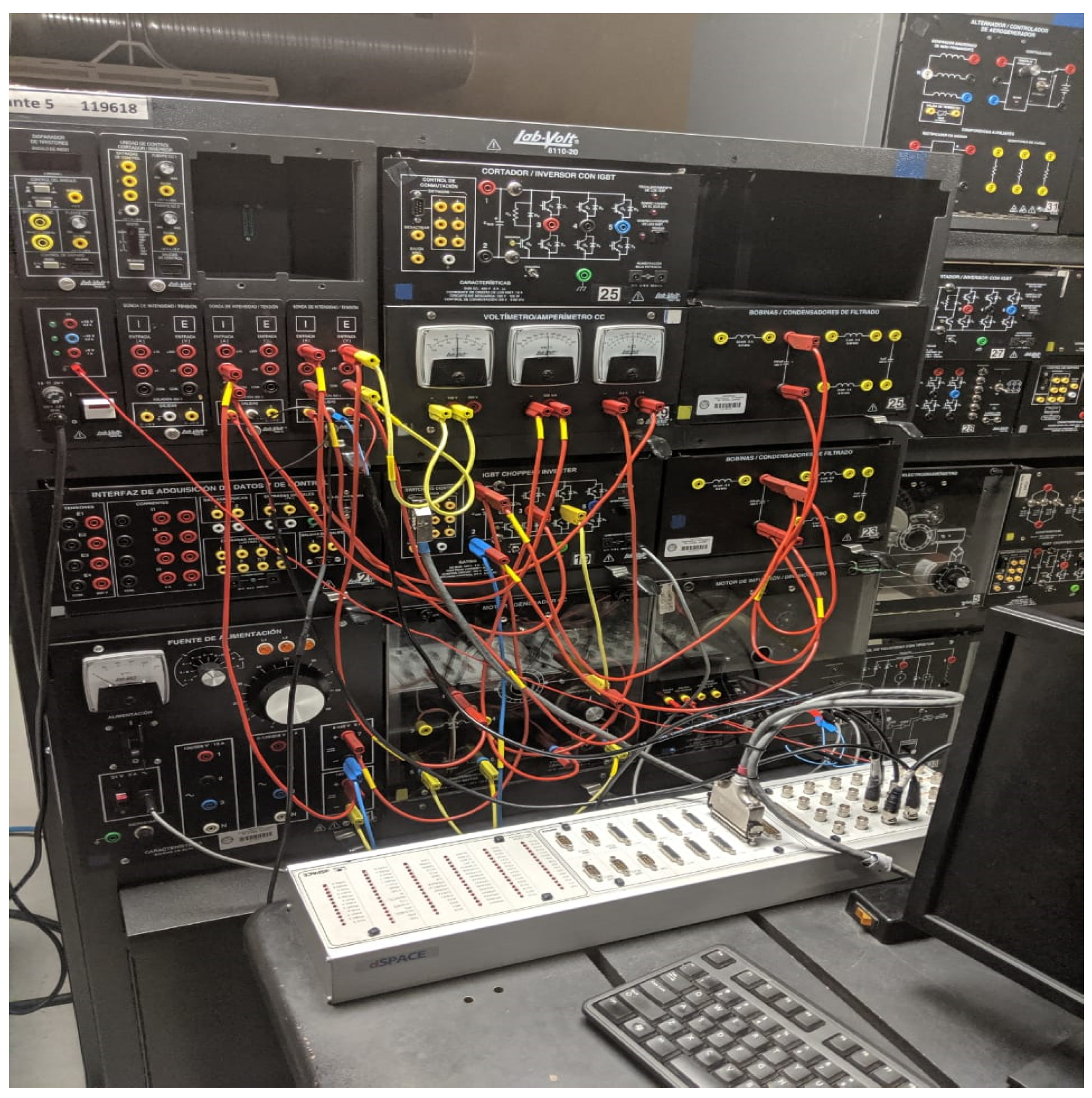
The experimental validation of the wind turbine emulator was performed in a laboratory and the emulator is composed of the following:
A separately excited DC-motor (8211-02 LabVolt) coupled with a dynamometer (8960-12 Labvolt) via a belt; the dynamometer sets its load torque from the generator data sent by a virtual wind system through an input/output interface
A virtual wind system having one input, the wind speed, and two outputs, the rotor velocity reference and the turbine torque
A sensorless DC motor velocity controller to track the output velocity of the virtual wind system; the velocity controller includes a robust sliding mode observer to estimate the rotor velocity and a robust differentiator to estimate the first-order time derivative of the velocity tracking error
The software and hardware necessary to perform the experiment, using the dSPACE 1103 kit, a power supply, AC-DC mono-phase converter, and only one sensor, to measure the armature current
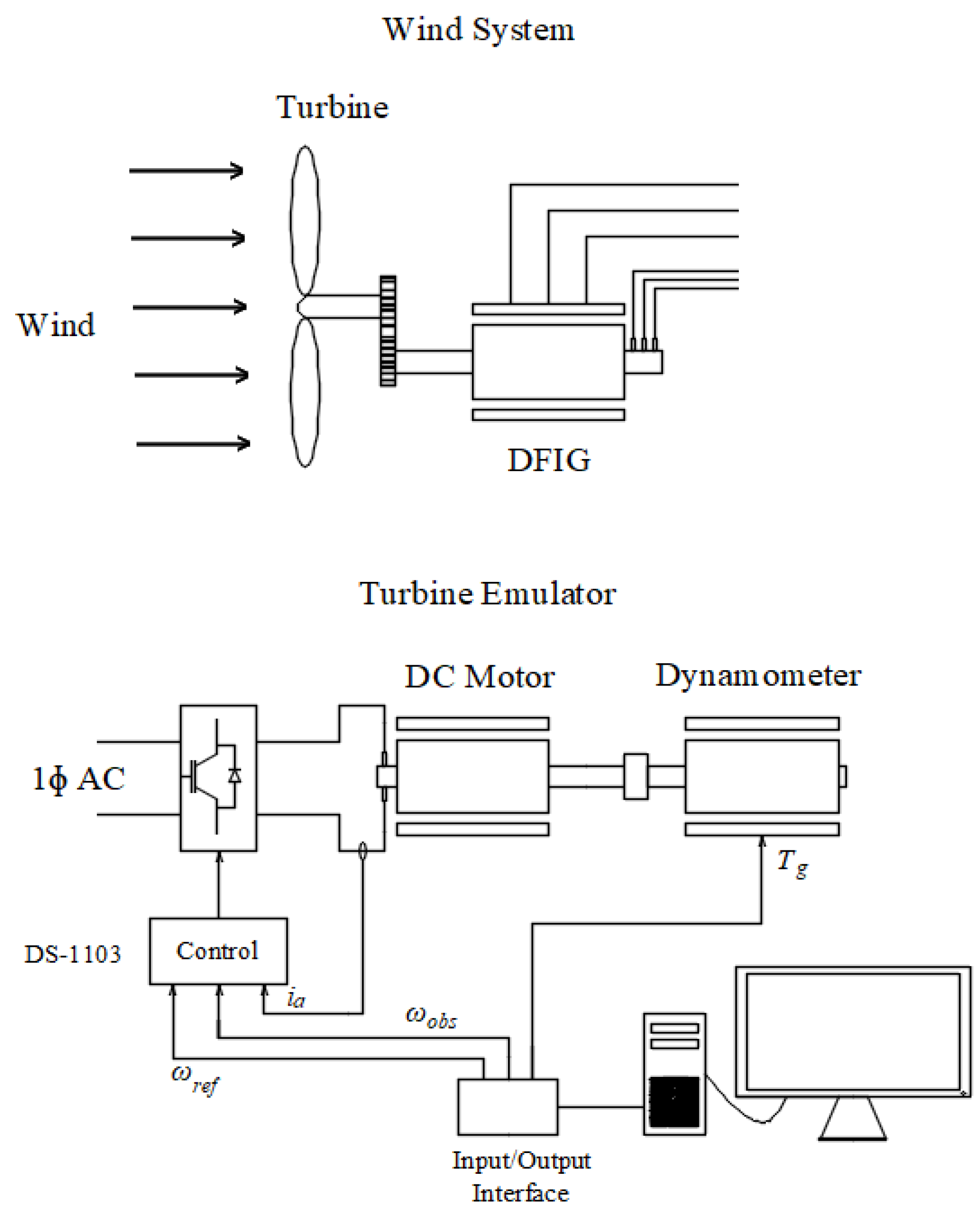
The dSPACE 1103 kit is composed of a control target, an input–output interface, and visualization software, among other components. The scheme of the wind turbine emulator is shown in
Figure 2, while the workbench where the experiment was performed is shown in
Figure 3. The wind turbine parameters are presented in
Table 1 and the nameplate data and DC motor parameters are presented in
Table 2.
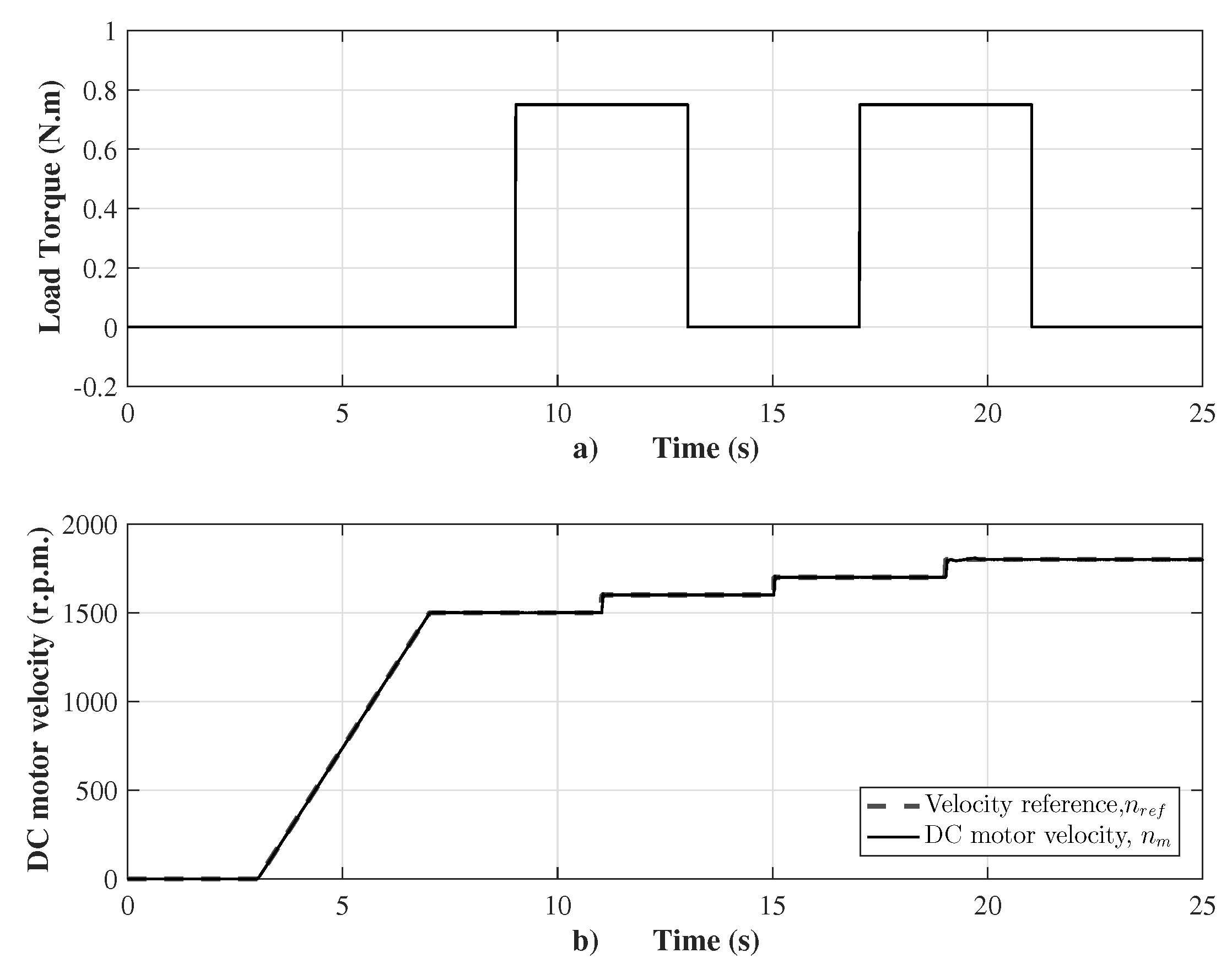
Before presenting the emulator performance, a robustness test of the proposed sensorless velocity controller was setup. The source program was codified using Simulink/Matlab with a sample time of 100 μs. The motor velocity was controlled from standstill tracking a ramp until 1500 r.p.m., and then sudden changes of the velocity reference in step form are presented together with sudden changes of the load torque by means of two pulses, as shown in
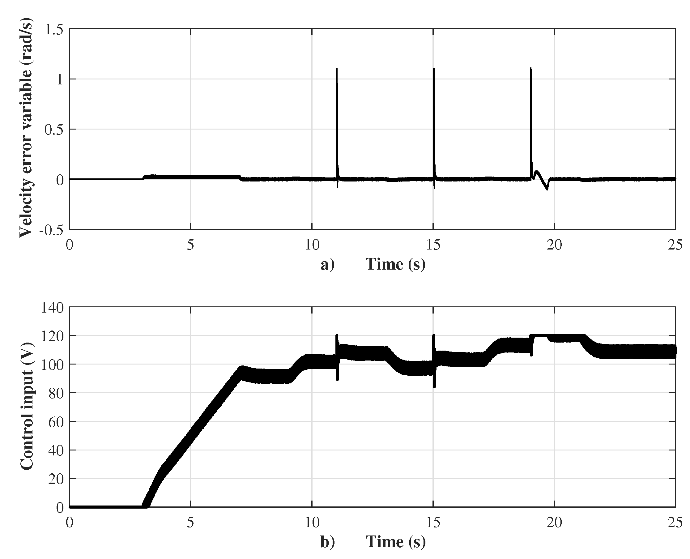
Figure 4. The ramp reference increases from the standstill with a slope of 375.1 r.p.m./s to 1500 r.p.m. with a steady state error of 0.2%, and, subsequently, in Second 11, three steps of the velocity reference with a magnitude of 100 r.p.m. during 4 s are setup. When the velocity reference changes from 1700 to 1800 r.p.m. at Second 19, the motor velocity response has a settling time of 0.76 s, an overshoot of 9%, and steady state error of 0.8%. The external disturbances appear in Second 9, with two pulses of the load torque that vary from 0 to 0.75 N.m (corresponding to a load factor of 75%) during a period of 8 s. It is important to remark that the sensorless velocity controller is robust when the load torque changes are presented due to the action of the super-twisting control law. The performance of the controller is shown in
Figure 5. The control input has average chattering of 8 V. When the velocity reference changes suddenly, a sudden change of the velocity error variable to 1.2 rad/s is presented, as shown in
Figure 5a.
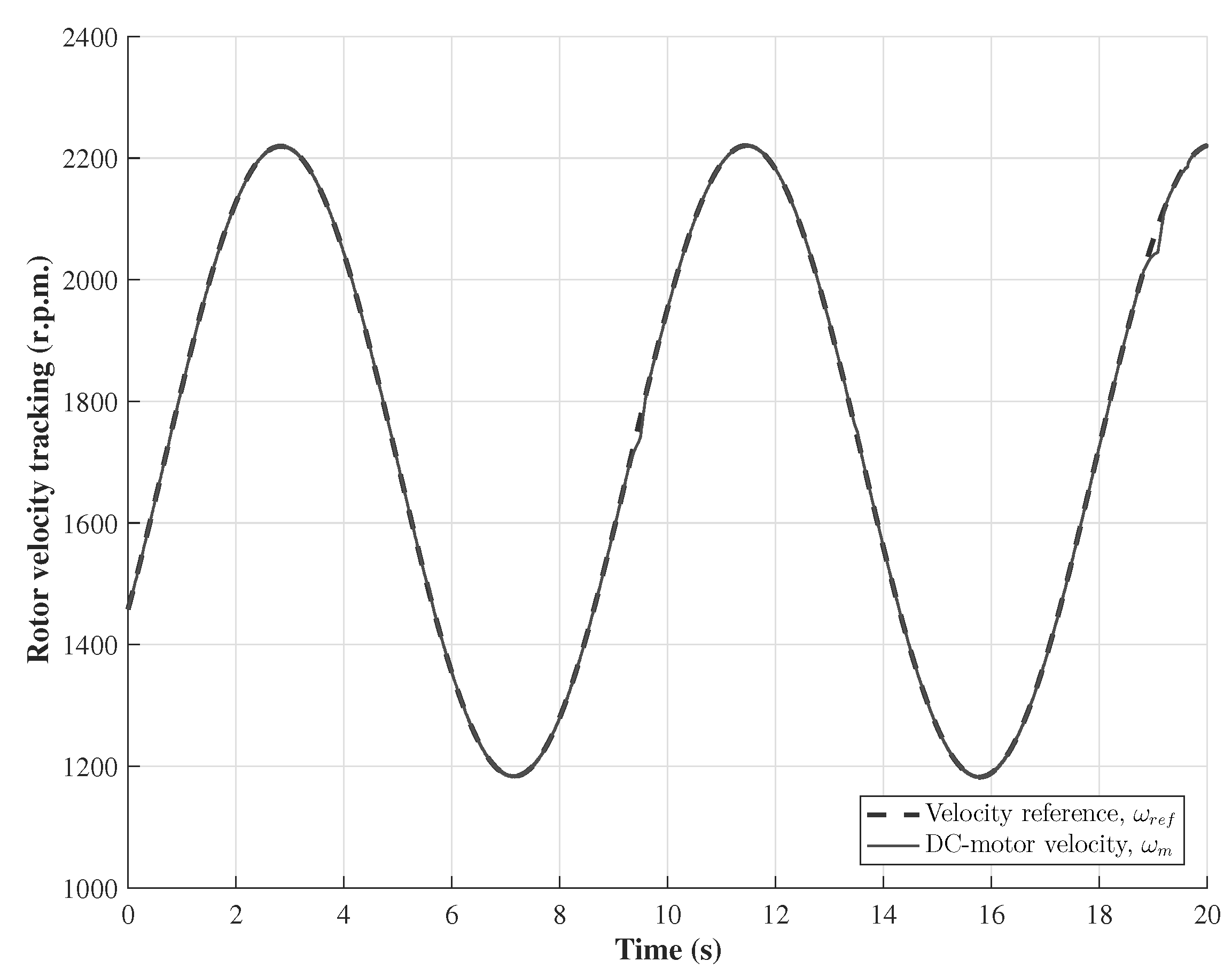
The main test corresponds to the wind turbine emulator performance, which is shown in
Figure 6. It is observed that the DC motor velocity
tracks closely the velocity reference
set by the virtual wind system, and, thus, the control goal is achieved, i.e., the emulator behaves as a wind turbine. The tracking of the oscillating velocity reference is accurate, as observed in
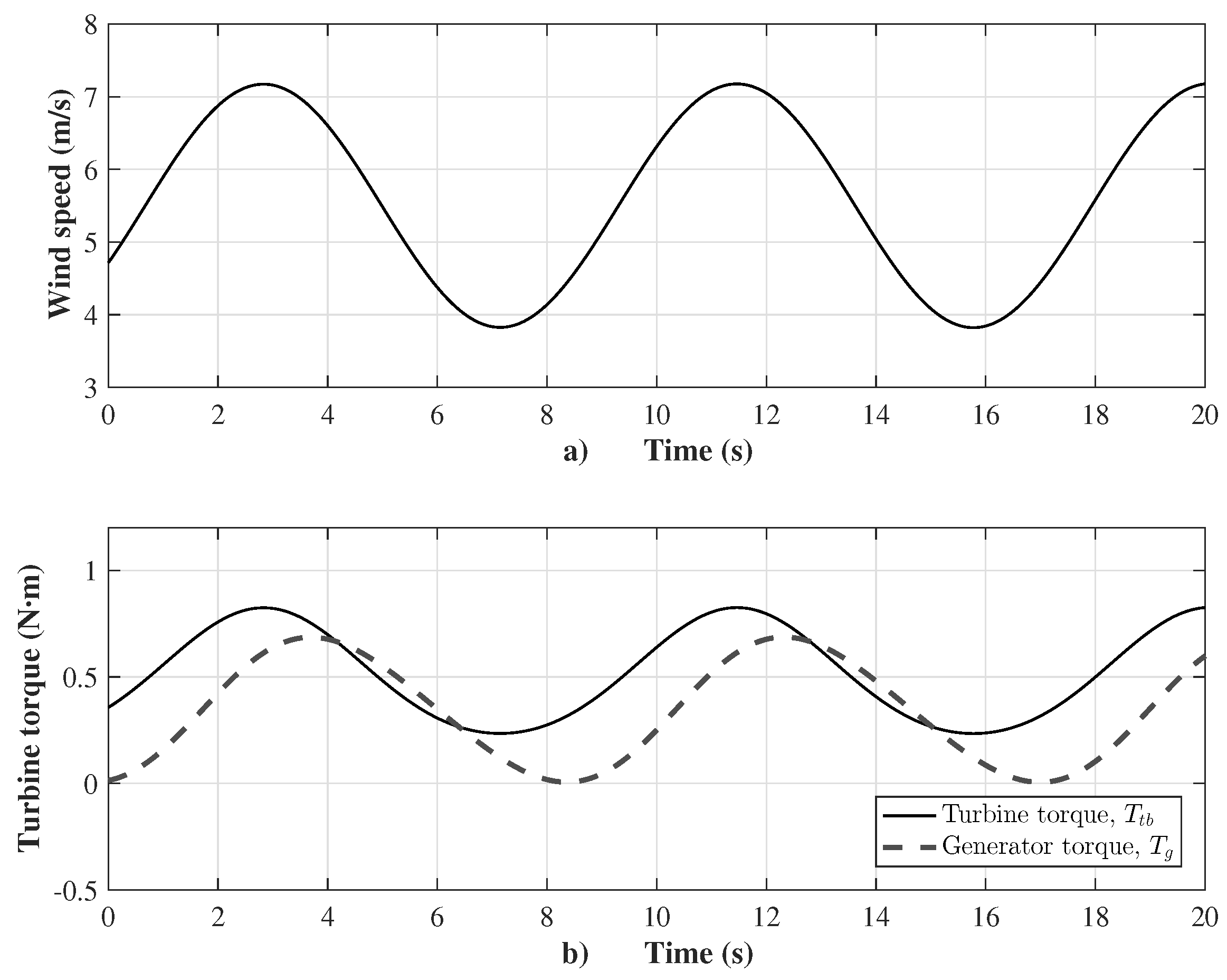
Figure 6. The velocity reference oscillates from 1186 to 2221 r.p.m. due to the wind speed, oscillating approximately from 3.8 to 7.2 m/s, with a time period of
s, as shown in
Figure 7a, being the wind speed the input of the virtual wind system. Besides, the wind velocity oscillation causes oscillation of both the wind turbine torque
(from
to
N.m) and the generator torque
(from
to
N.m); the time period of oscillation of these two signals is
s, as shown in
Figure 7b. The generator torque
is made to match with the reference torque defined in Equation (
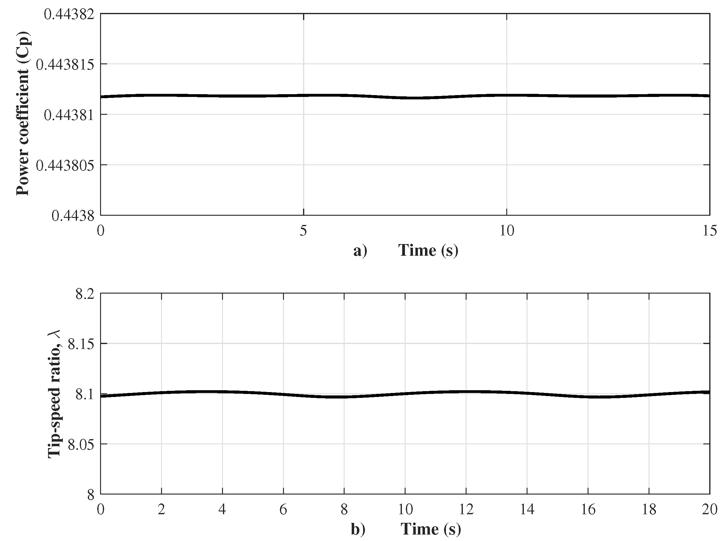
9). This mode of operation is achieved when the torque of the generator is controlled, and, consequently, the captured wind energy is maximized. Therefore, the power coefficient
maintains a value of
near its maximum value, as shown in
Figure 8a, and the corresponding desired value of tip-speed ratio
is maintained at
, as depicted in
Figure 8b.
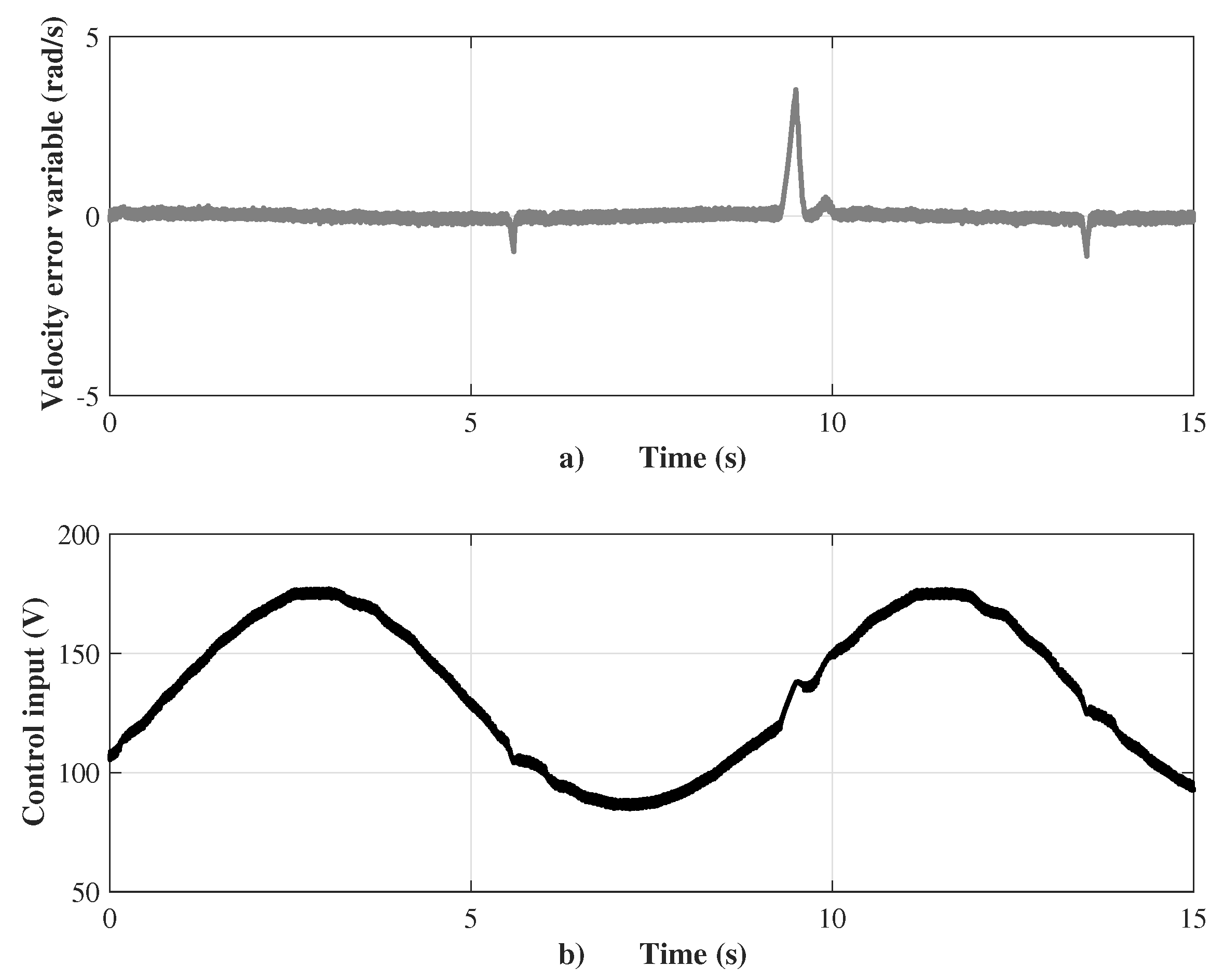
Figure 9a shows that the velocity error variable stays close to zero at high frequency, while the control input, as the voltage supply to armature winding of the DC motor, varies from
to 177 V with an average chattering of 2 V, as shown in
Figure 9b. The sensorless velocity controller applies the super-twisting control law of sliding modes (
27), which was tuned with the gains
and
, according to restrictions setting in (
29) and (
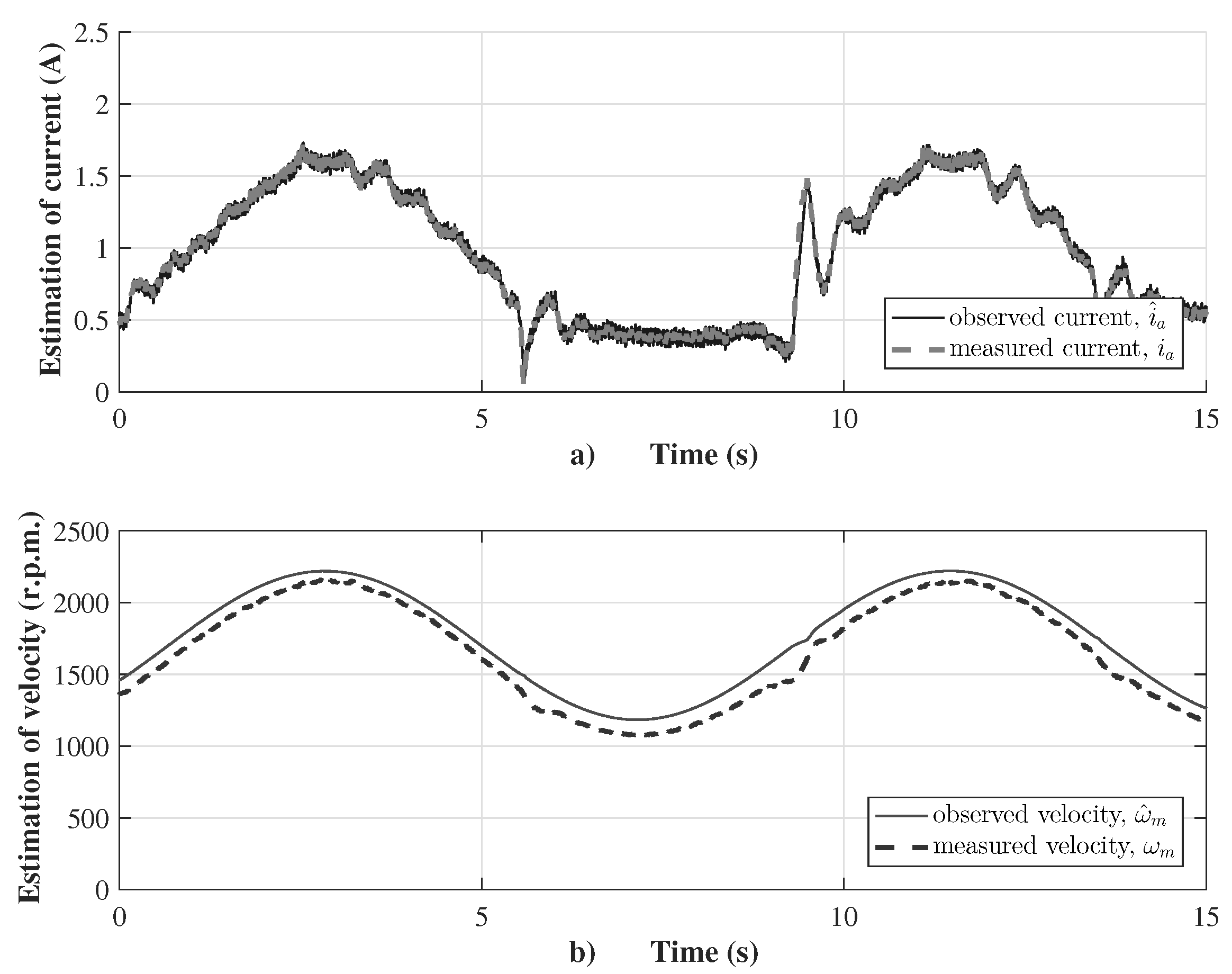
30). The velocity observer performance is shown in
Figure 10, where the observed current
is almost the same as the measured current
, as shown in
Figure 10a. This guaranties a good estimation of the velocity
via the robust observer, which is compared with the measured velocity
for validation purposes (see
Figure 10b). The robust velocity observer applies a discontinuous input of first-order sliding modes to adjust the observation variables, which was tuned with gains
to vanish the velocity estimation error to the origin, using the discontinuous input
to force the current estimation error to the origin in finite time (
12).
6. Conclusions
This article proposes a design methodology and its implementation in real-time of an emulator to the operation of a wind turbine. The proposal consists of mimicking the turbine operation through a separately excited DC motor driving by a sensorless velocity controller that tracks the output velocity of a virtual wind system. The velocity controller is distinguished by being sensorless because the rotor velocity is estimated through a robust observer and uses only the armature current measurement. In the design of the sliding variable, a robust differentiator is applied and tuned to estimate the first-order time derivative of the velocity error variable, thus avoiding its calculation that involves the load torque, which is commonly estimated via an asymptotic observer. A robust observer is proposed to estimate the rotor velocity being adjusted through a discontinuous input having as argument the armature current observation error. On the other hand, the super-twisting control law is applied to force the movement of the sliding variable and its first derivative simultaneously towards zero, and, with this, an asymptotic movement of the velocity tracking error towards zero is achieved. Experimental results are presented where a virtual wind system has one input, an oscillator-shaped wind speed, and two outputs, the wind system velocity and the electromagnetic generator torque, whose digital signal is sent to the dynamometer to establish its load torque. The validation of the proposed sensorless velocity controller is evaluated by presenting and interpreting graphic results. The tracking graph, where the motor velocity tracks the output velocity from the virtual wind system, shows that the control goal is fulfilled, which consists of emulating the turbine operation. In addition, the good performance of the robust velocity observer is validated by minimizing the estimation error of the armature current. With the emulator’s proposal, research related to wind systems can focus on the control of the electric generator, such as achieving the control goals of the wind power system, integrating the wind system operation into a smart grid, or performing stability analysis in the utility grid, among other studies.


 ,
, 


