1. Introduction
Regional energy distribution networks are increasingly supplied by renewable electricity. Production from these energy sources, such as wind and solar, is dynamic by nature. These electricity and gas networks are also connected to an increasing amount of geographically distributed energy sources (such as the abovementioned renewable electricity and biogas). Additionally, the electrification of the heat demand in the built environment leads to more dynamic demand by the users. A grid planning model was developed in [
1], investigating the interdependencies of the electricity and gas strategy of DSOs (Distribution System Operators) and the future role of the gas network in the energy system.
As a result of more dynamic supply and demand, reliable operation of these hybrid energy networks becomes more complex. In order to supply energy to the users at all times, congestion should be avoided. However, increasing the capacity of the electricity network leads to high investment costs. In [
2], a model was developed for co-planning of the expansion of electricity and gas distribution networks, incorporating investment and operation costs.
P2G (power-to-gas), for example the conversion of electricity to hydrogen using an electrolyzer, creates the opportunity to use the existing gas distribution network for energy storage, thereby reducing the peak load in the electricity network. In [
3], the implications of different P2G technologies on electricity and gas transmission networks have been assessed.
Through this integration of electricity and gas grids, additional flexibility is created to reliably deliver the energy to the users. For optimal operation of these integrated grids, timely information on supply and demand as well as identification of bottlenecks is required. The integrated operation of electricity and gas networks under uncertainty in commodity prices and energy supply and demand was investigated in [
4].
From a reliability perspective, it is important that the operational constraints, such as the transport capacity, are met. Additionally, events such as pipe failure should be handled to minimize the risk of not delivering energy to the user. Therefore, it is important to quantify risks in integrated electricity and gas networks.
Already in the design phase of the networks, insight is required to increase the security of supply and reduce investments costs. In [
5], an integrated model was applied to the operation of electricity and gas transmission networks, making better use of line pack (the amount of gas that can be stored in gas pipelines) and reducing the operational costs of the networks.
In the operational phase, the security of supply should be guaranteed using an up-to-date operational model and supply/demand profiles. In [
6], the security of supply in combined electricity and gas transmission networks is analyzed. The developed simulation tool SAInt (Scenario Analysis Interface for Energy Systems) quantifies the impact on security of supply, e.g., using the parameter energy not supplied, in both electricity and gas networks.
In this paper, firstly, a stochastic method to quantify the security of supply in electricity and gas distribution networks with a large number of geographically distributed constraints, energy suppliers and users is presented. This method has the capability to quantitatively evaluate the security of supply for individual users in these distribution networks, given the likelihood of failure of individual components (such as pipes) and constraints related to pressure boundaries and gas flow rate and composition among others. Secondly, a method for coupling electricity and gas distribution networks is proposed to assess the operational performance of hybrid energy distribution networks.
The electricity network solver (Matpower, [
7]) performance has been examined in [
8]. The background and accuracy of the gas network solver used in this study has been explained in [
9].
In
Section 2, we develop the mathematical model to solve the integrated electricity and gas networks. In
Section 2.3, we describe the security of supply method and associated KPIs (Key Performance Indicator). Finally, in
Section 3.1, the functionality of the security of the supply method is demonstrated on a real gas distribution network case study. The integrated electricity and gas network model is also demonstrated in
Section 3.2 on a hybrid energy network case study (real gas distribution network coupled to a simplified electricity network).
2. Methodology
Assessing the security of supply in hybrid energy networks requires an integrated simulation model that solves gas network equation and electricity network equation and also solves the interaction between these two models. Therefore, we use our own proprietary gas network solver (AURORA) and an open-source electricity network solver (Matpower).
2.1. Network Solvers
2.1.1. Electricity Network Solver
Matpower [
7,
10] is a package of Matlab
® M-files for solving power flow and optimal power flow problems. This solver solves a set of equations involving voltages and currents in the network based on model inputs.
The models are divided into two components (branches and buses). All transmission lines and transformers are modeled as branches. All generators and loads are modeled as power injections and power consumed at a bus.
For each bus, we compute the real power (MW), reactive power (MVar), Voltage magnitude (V) and Voltage angle (deg). Each branch contains information about real power injected (MW) from/to a bus, reactive power injected (MVar) from/to a bus and branch Current magnitude (A).
2.1.2. Gas Network Solver
AURORA is a TNO proprietary solver for computing pressure, flow and composition in a distributed gas network.
The models are divided into two components (lines and nodes). All transport pipes are modeled as lines. All gas suppliers, gas consumers, pressure reducing stations and compressors are modeled as a node.
The basic approximate steady-state equation of the pressure drop in pipelines due to friction can be computed from the mass balance and energy balance [
11]. This solver can handle both static (steady-state) and dynamic (transient) behavior of the system.
2.1.3. Hybrid Network Solver
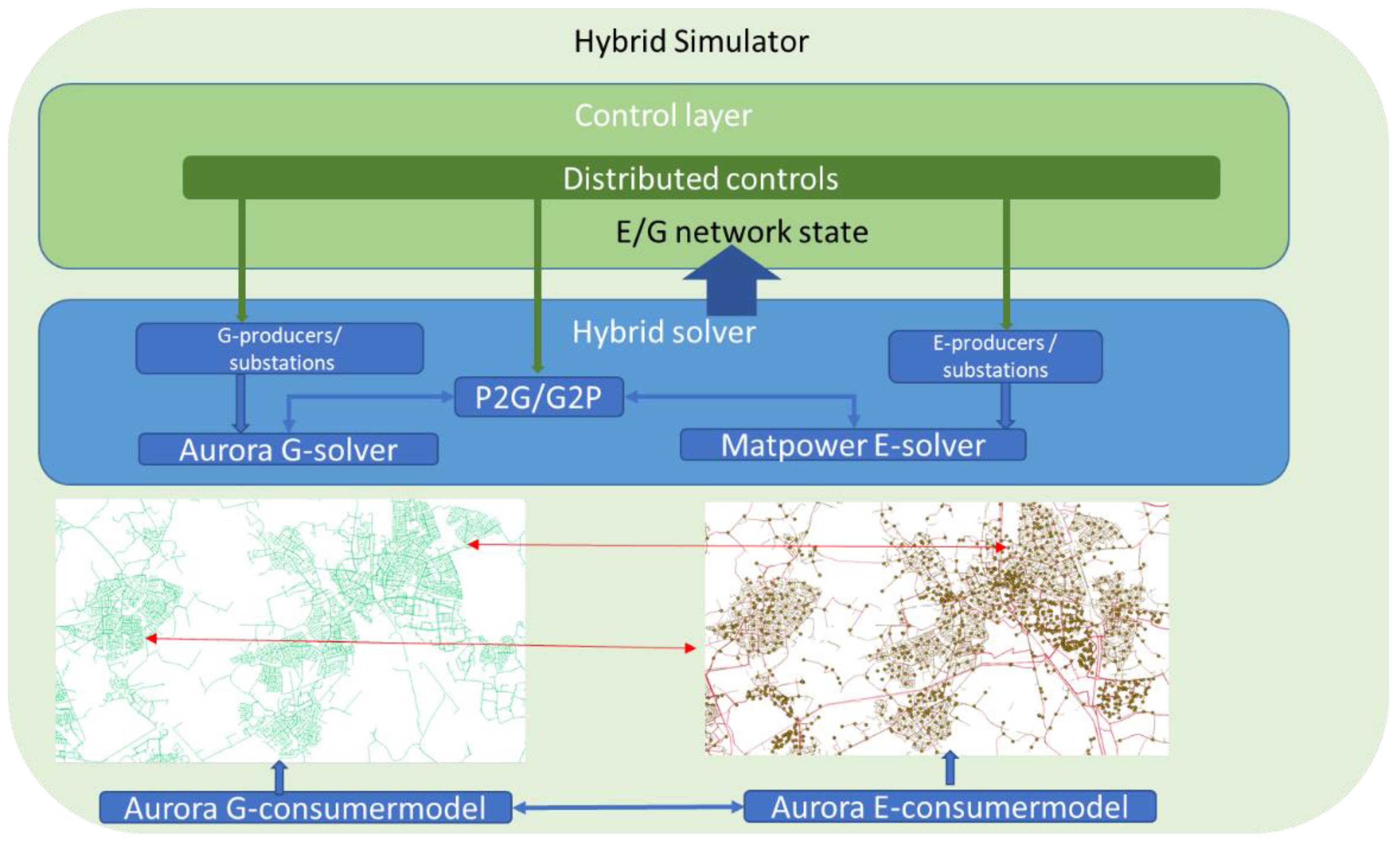
The energy/mass flows in the network are calculated by single commodity model solvers. The interaction between the different commodities (electricity or gas (E/G)) is handled by a hybrid solver. The hybrid solver manages the interaction between networks at all distributed interaction points (
Figure 1).
The interaction arises from:
Direct physical coupling (Power To Gas (P2G), Gas To Power (G2P)) conversion components in the network;
The control strategies implemented in the control layer of the simulator;
Consumer decisions on the selected mix of commodities for their energy demand.
In practice, the control strategies implemented at the different geographically distributed locations are local control strategies, using local measurements of pressure, flow, voltage or current. Interaction between the controllers is indirectly dictated by network physics and consumer behavior.
Because of the distributed nature of hybrid network interactions, especially if there are multiple conversion units, network simulation serves as an important performance evaluation tool. In case study 2, a regional network is simulated over a period of five months, using weather station data and time-dependent behavior of consumers. Already with only one Power to Gas conversion unit this leads to control strategies that need to include logic to handle bottlenecks.
2.2. Hybrid Coupling and Constraints
The gas network and the electricity network are coupled by the conversion components Power to Gas (P2G) and Gas to Power (G2P).
A P2G unit has two types of control:
QO (Output flow control), which maintains the gas output flowrate of the component based on the flow setpoint;
EI (Input power control), which maintains the power input based on the required power setpoint.
A G2P unit has 2 types of control:
QI (Input flow control), which maintains the gas input flowrate of the component based on the required flow setpoint;
EO (Output power control), which maintains power output based on the power setpoint.
As long as the conversion unit production is within the boundary conditions of each individual network, the networks can be individually simulated. More complex interactions results if one of the networks hits operational boundaries, as is conceptually depicted in
Figure 2.
Suppose P2G is on QO control with
. Neglecting line pack, the mass balance (Equation (1)) has to be satisfied:
As long as Qsupplier > 0, the results are valid. However, if Qsp > Qconsumer, then no valid solution exists, leading to a pressure build-up in the network. In practice, to avoid a shut-in of the gas network, the P2G unit has to scale down its produced gas flow, leading to a different behavior of the electricity network. The hybrid network solution, thus, depends on the control schemes for the conversion units.
The interaction in a hybrid gas/electricity network is demonstrated in case study 2 (
Section 3.2).
2.3. Security of Supply
DSOs require close to 100% delivery of demanded gas and power to its consumers. Security of supply can be expressed in terms of (1) the number of expected time interval of not being able to satisfy consumer demand over a time period of typically one year and (2) the impact that events have on consumers.
These two aspects can be combined by defining performance criteria that both weigh the time and the number of affected consumers.
A network, where all components are functioning properly, has a certain security of supply level. In practice however, performance is also affected by stochastic events, such as a pipe break, substation failure, power line failures.
The probability distribution of basic events, such as pipe breaks, depending on pipe material, age and soil conditions, or station failure probability, is usually available to the DSOs. It can be represented by a Poisson distribution, which is in turn represented by a λ-parameter, showing the expected number of events per time. In order to determine the effect of these random events on the security of supply on the network level, it is necessary to quantify network performance. To do so, a set of Key Performance Indicators (KPIs) are defined, as listed in
Table 1.
The KPIs are computed after a deterministic simulation is performed. For example, the computation of CML_P is explained. For a simulation of
n timesteps of length Δ
t minutes, a Boolean expression is calculated at each customer site
c = 1…
nc. The number of customers is
nc. The value of the Boolean expression is 1 if the local pressure,
Pt,c, is smaller than the minimum allowable pressure,
Pmin,c, at costumer
c at time
t (Equation (2)). Thus, if the condition
Pt,c <
Pmin,c is met, the value is 1; otherwise it is 0.
The expected value of a certain KPI due to a random event
X can in principle be computed using the known probability density function
fX(
x) of
X by Equation (3):
In the network case, the probability of a certain event (e.g., pipe break) depends on pipe properties, such as the length of the pipe, pipe material and pipe age, and therefore, this leads to different probabilities for the pipe break per pipe.
Direct calculation of the expected value of the KPI from the joint probability distribution is intractable. It is, therefore, replaced by a Monte Carlo method [
12], approximating the expected value by random sampling of the probability distribution functions, calculating the KPI value for each sample and computing the average value and variance of the KPI over all samples.
The network is simulated over a representative period of time to include typical weather and consumer demand variability. A large number of Monte Carlo simulations is performed, each with basic events happening according to their probability distribution. The KPIs are calculated per stochastic simulation and normalized over the period length. The estimated KPI values are more realistic than the typically used “worst case” performance used by DSOs. The method is demonstrated in case study 1 (
Section 3.1).
3. Case Studies
3.1. Gas Network Case
In this case study, we will present the results regarding security of supply in the gas network. There are two scenarios that will be assessed. The first scenario is to analyze the normal operation of the gas network during peak demand (winter period). The second scenario is to analyze the impact on customer (CML_P) due to a random pipe failure/maintenance for a 3-bar pipeline in the network.
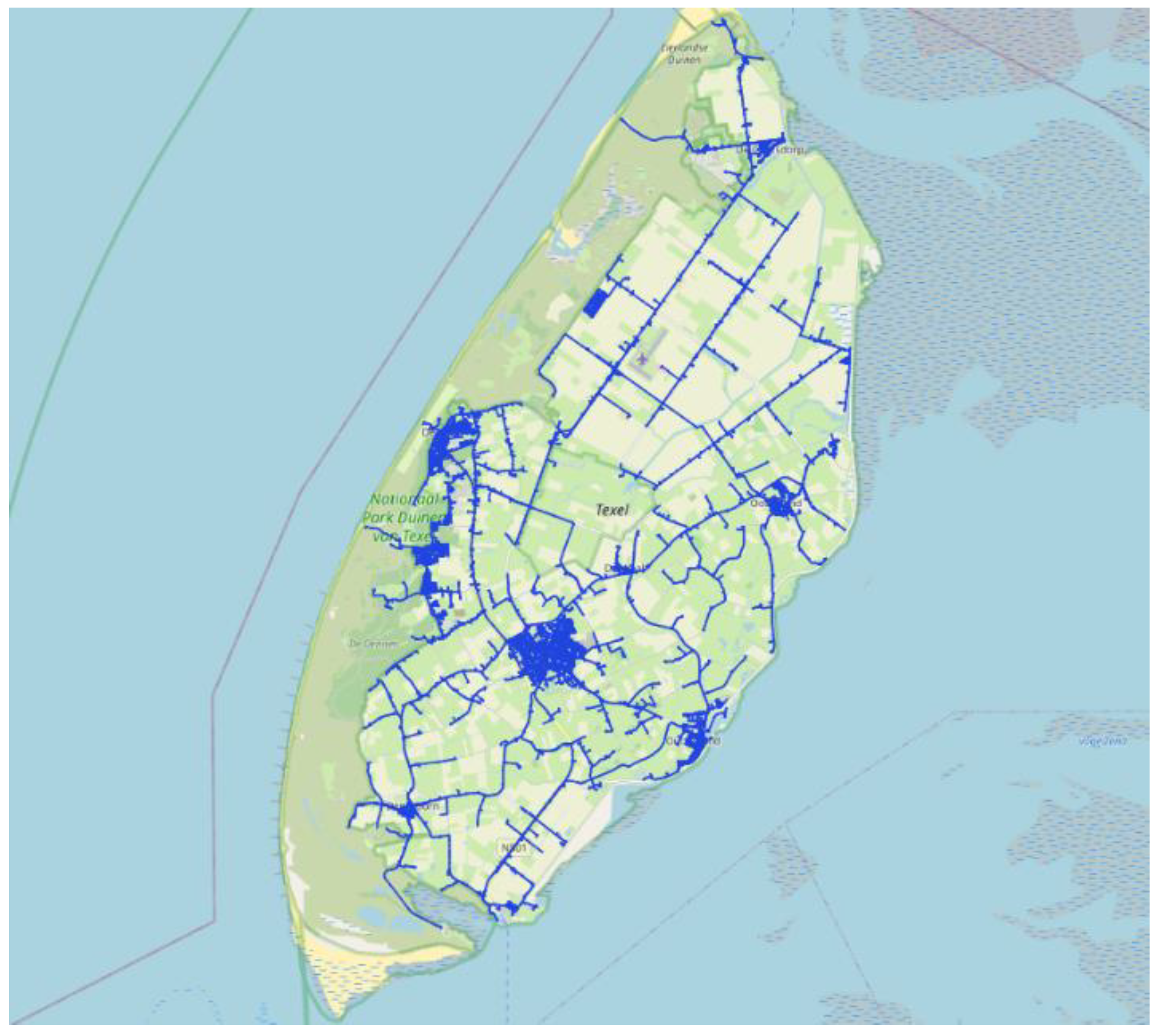
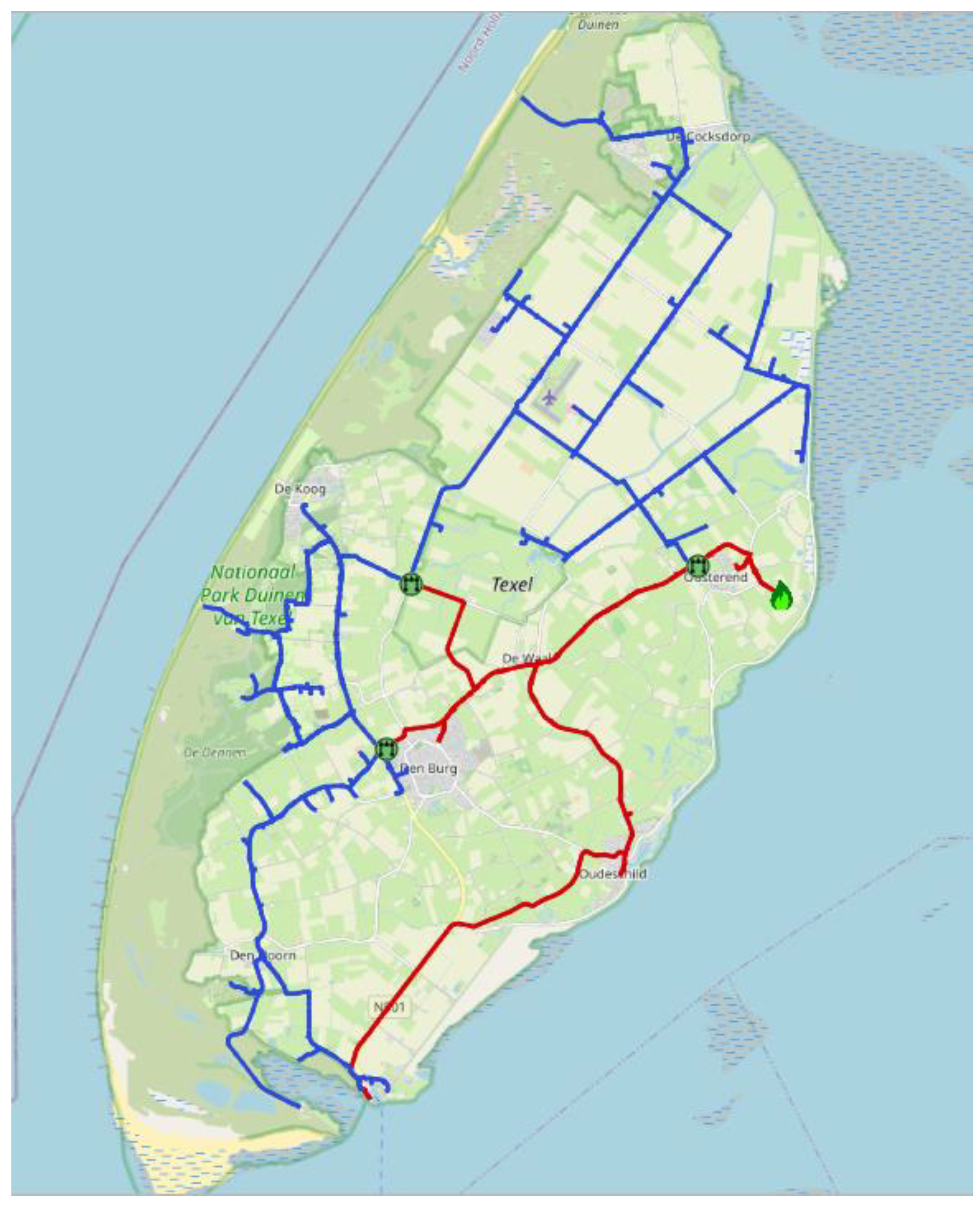
We model a gas distribution network on Texel. Texel is an island located in the province North Holland, the Netherlands. This network has more than 22,000 pipes, 8000 customers, 400 pressure reducing stations and one gas supplier injection point (
Figure 3). The network has three different pressure regions (8 bar, 3 bar and 100 mbar). The customer has a minimum required pressure of 20 mbar in the inlet of the house.
The gas network was simulated for 1 month during the winter period in February 2017. We assessed the security of supply in the gas network with normal operation and with pipe break events.
3.1.1. Normal Operation (Base Case)
This base case scenario was simulated for one month in February. There was no pipe failure/maintenance during this period.
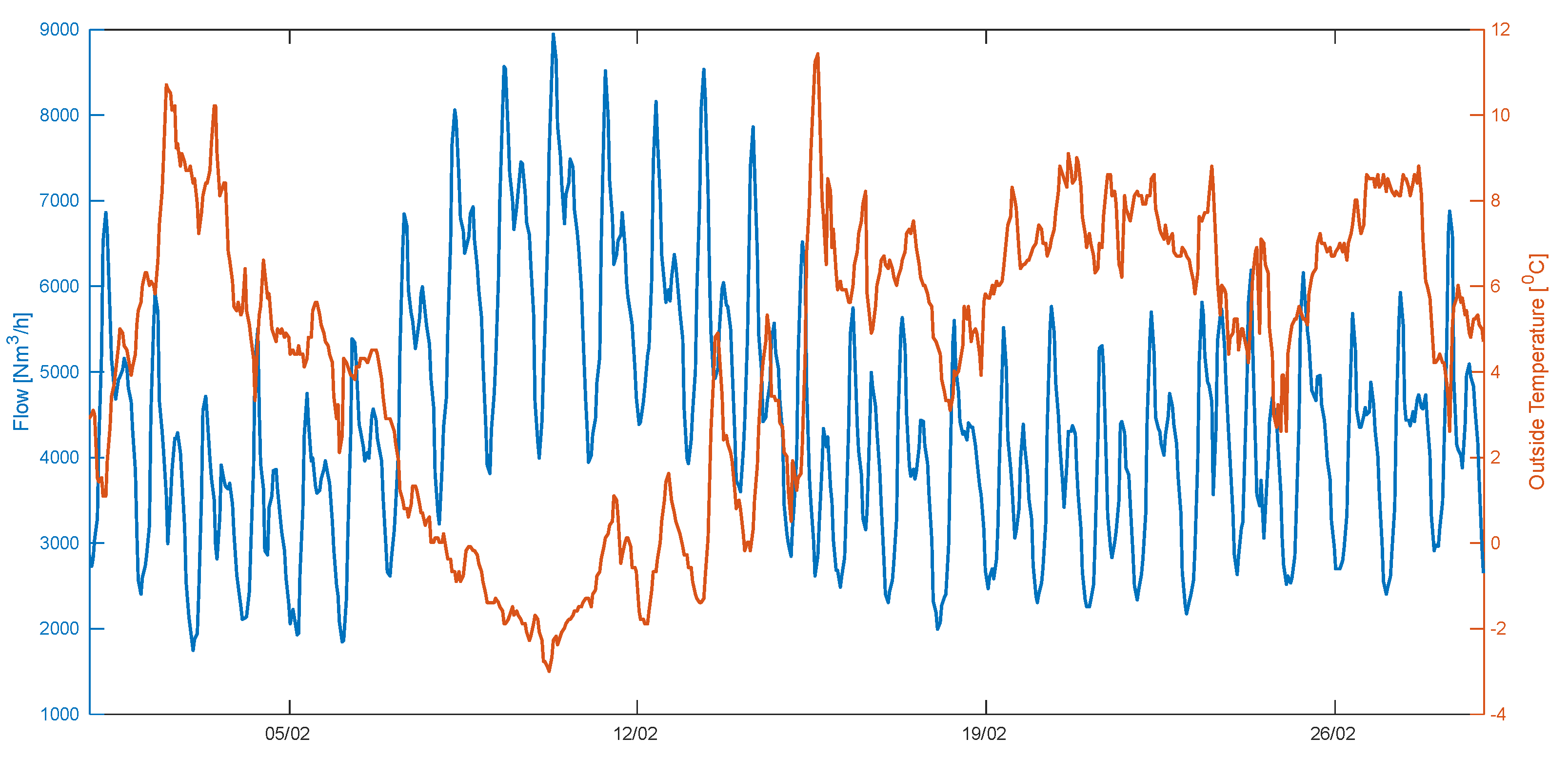
Figure 4 shows the total gas flowrate modeled by our consumer model using the DSOs’ open data from [
13] and measured weather profile from Koninklijk Nederlands Meteorologisch Instituut (KNMI) [
14] between the 1st of February 2017 and the 1st of March 2017. The maximum gas consumption in the network occurs on the 10th of February at 08:00. It is around 9000 Nm
3/h.
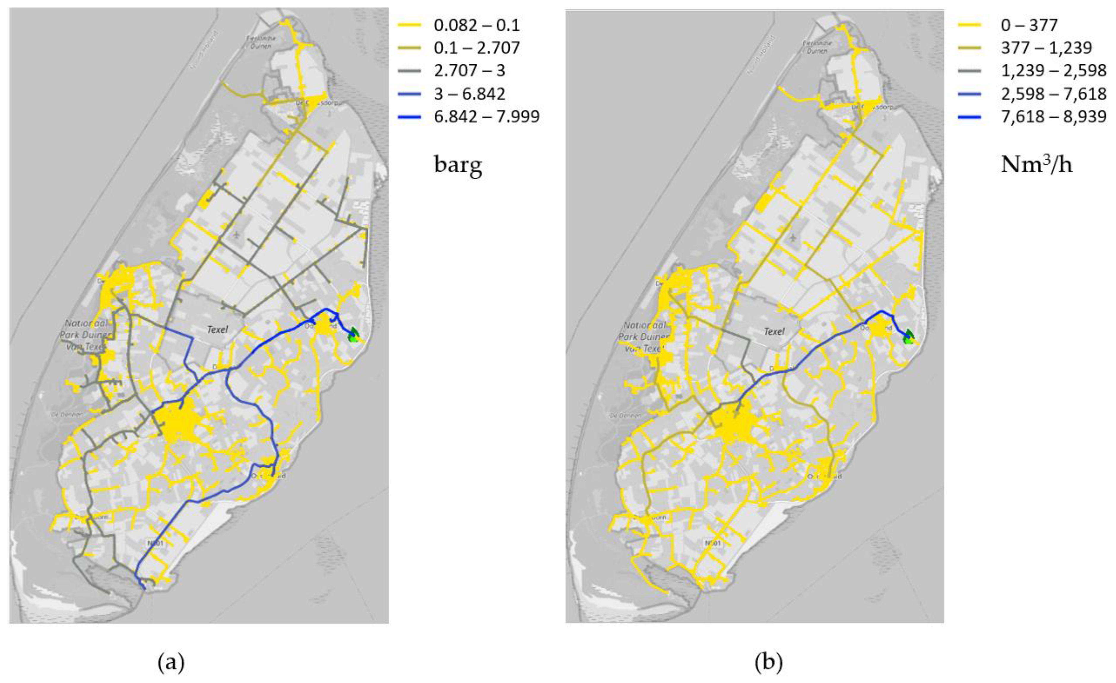
As shown in
Figure 5, the minimum pressure in the network is 82.02 mbar during the peak hour at 08:00; thus, supply to all customers is guaranteed.
3.1.2. Security of Supply at 3-bar Pipelines
The 3-bar pipelines of Texel are supplied from three pressure reducing stations from the main 8-bar network (see
Figure 6). The 8-bar pipeline to the south part of the island goes directly to the sea port. These 3-bar networks also consist of several loops.
Random pipe failures are simulated for the 3-bar network using a Monte Carlo method based on a typical failure rate presented in
Table 2, similar values have been reported by [
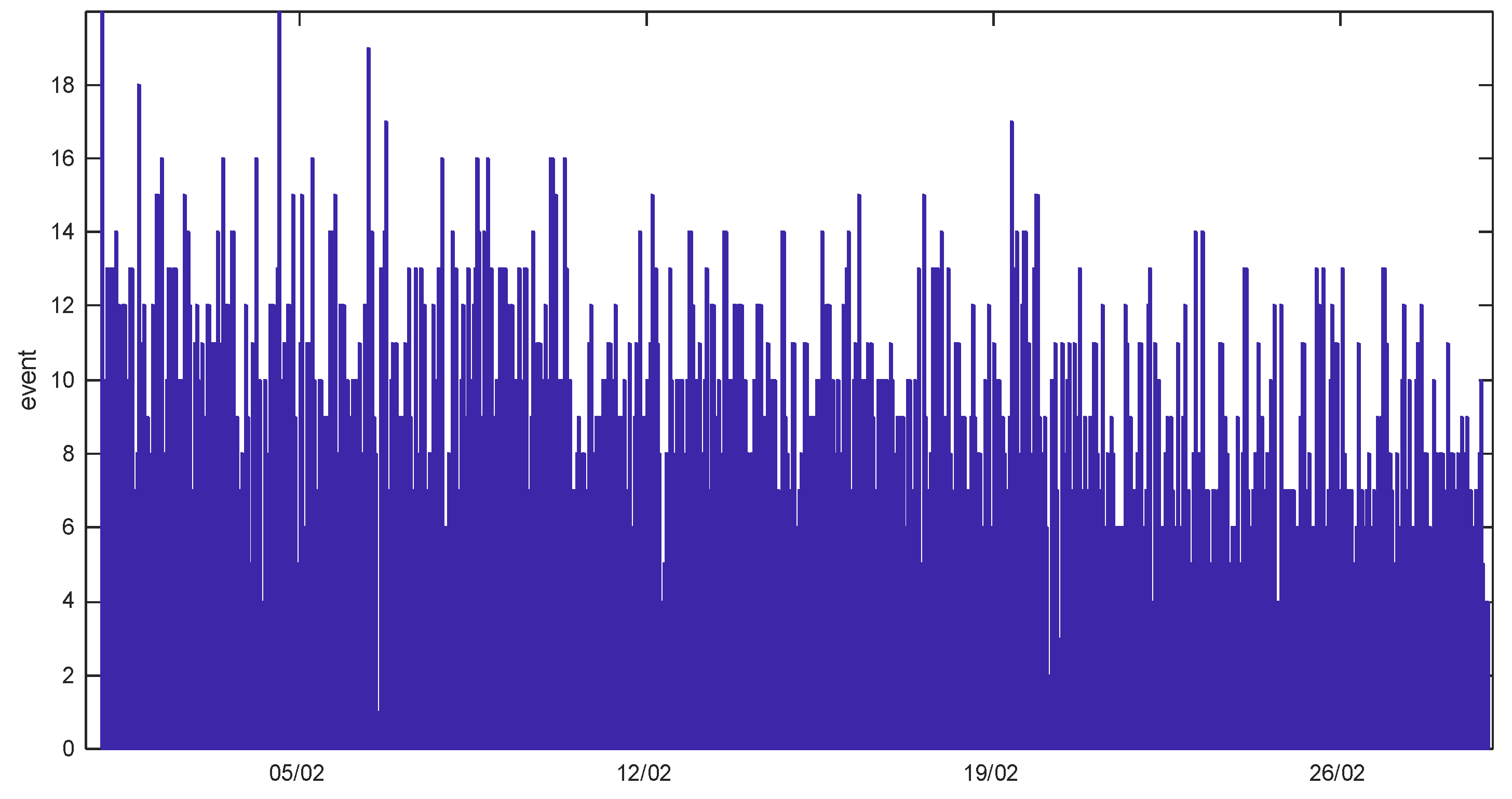
15]. This random event has a downtime period of four hours to perform a maintenance. In total, 21,000 independent simulation runs over the month of February were conducted, where in each simulation, one to several random events took place, with the probability density function for the basic event values as specified in
Table 2, resulting in zero to several events per simulation. The events distribution in time is depicted in
Figure 7.
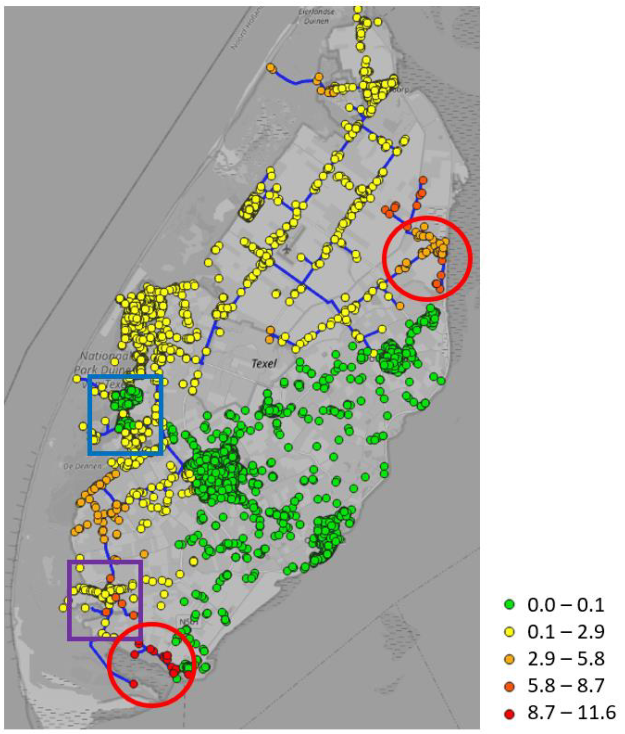
Figure 8 shows the Customer Minutes Lost (CML) for each customer due to a random pipe break event in the 3-bar network.
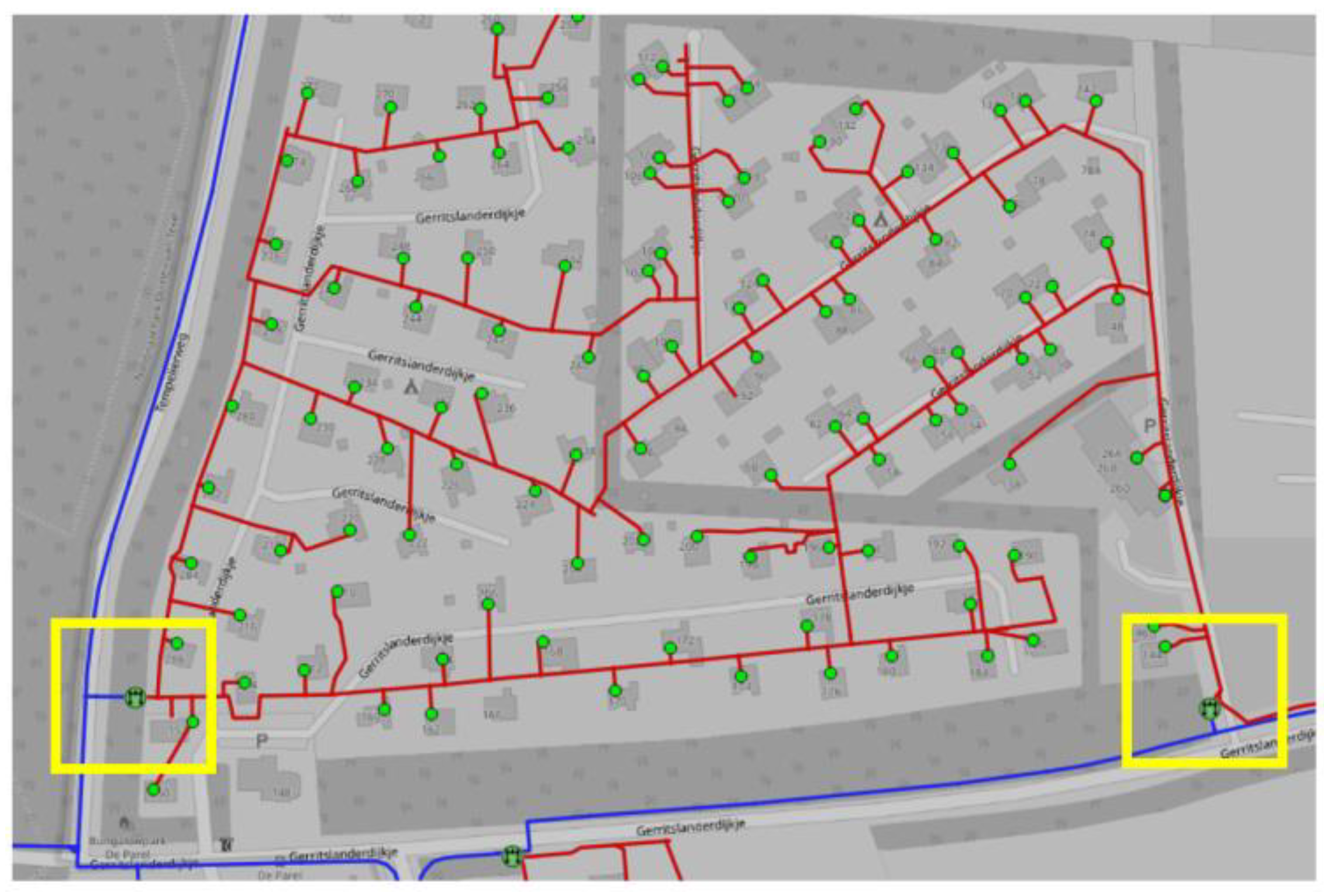
The customers located on the south-east side of the island have 0 CML, because they are directly supplied from the main 8-bar pipeline or 8 bar → 100 mbar stations. The highest CML is located in the red circle regions, but is simply explained, because these regions are supplied by a single 3-bar pipe. The customers located in the 3-bar loops have the lowest CML (yellow dot), because of network redundancy. There are two interesting regions, the customers located in the purple square and in the blue square. They both have lower CML compared to their close neighbors.
Some customers located in the blue square have 0 CML because there are two 3 bar → 100 mbar pressure reducing stations at both the east and west part of the neighborhood (see
Figure 9).
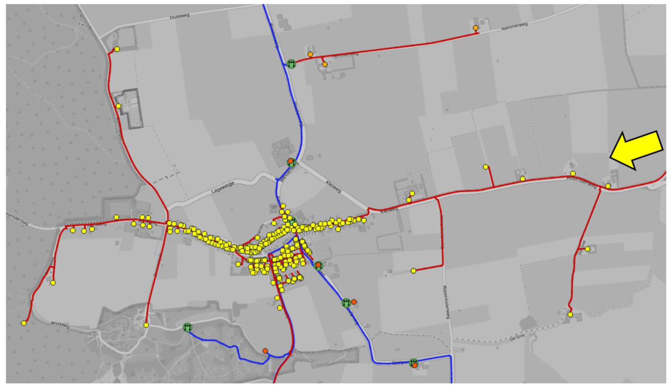
The customers located in the purple square (the south side of the island), logically should have a high CML because they are located almost at the end of a single 3 bar pipe. However, the customers in this neighborhood have a low CML because the gas is not only supplied from the 3-bar pipeline, but there is an additional 100 mbar supply entering from the east (see the yellow arrow in
Figure 10). The CML is not 0 because at peak demand times, the 100-mbar pipeline from the east is incapable to secure the minimum allowable pressure of 20 mbar.
Above, an analysis was made on security of supply for individual customers. A different perspective is to analyze which pipes have a large effect on the security of supply.
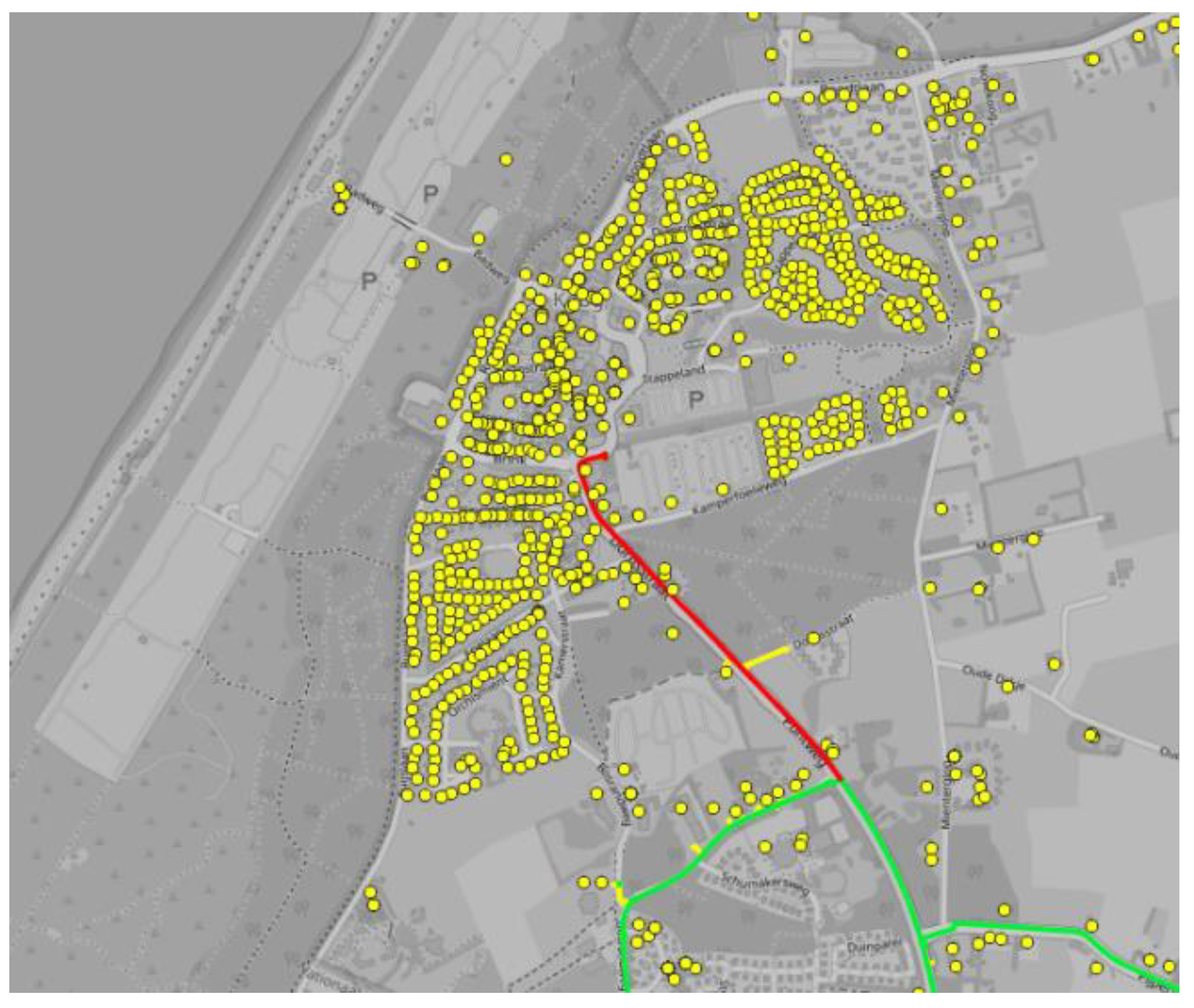
Figure 11 shows the total CML which can be attributed to each 3-bar pipe. The most critical 3-bar pipes are located in the blue square. These pipelines supply hundreds of customers and no redundancy is available (see
Figure 12). The safest pipelines are displayed in green color (0 CML). In these cases, there is a redundant 3-bar network pipe or a bypass to customers over an 8 bar–100 mbar pressure reducing station.
The calculated security of supply KPIs give insight into the most critical parts of the network w.r.t. gas supply, taking into account physical constraints and the likelihood of events. The outcome may be used for future planning and revamps of the network.
The computational time of the simulator varies and depends on the complexity of the network. For this case study, each time step can be solved in 0.5 s. It, thus, takes around 12 s for an hourly simulation in one day. More complex networks (e.g., through more loops in the network) can increase the computational time up to 20 s per timestep.
From the perspective of real-time decision making, we can use this simulator to do forecasting maintenance scenarios for the next 72 h using a demand profile based on the weather forecast. From the perspective of risk assessment analysis, running ~1000 scenarios with a maintenance duration around 3–4 h can be done in 1 h. If needed, we can parallelize the computation by splitting into several workers.
3.2. Hybrid Network Case
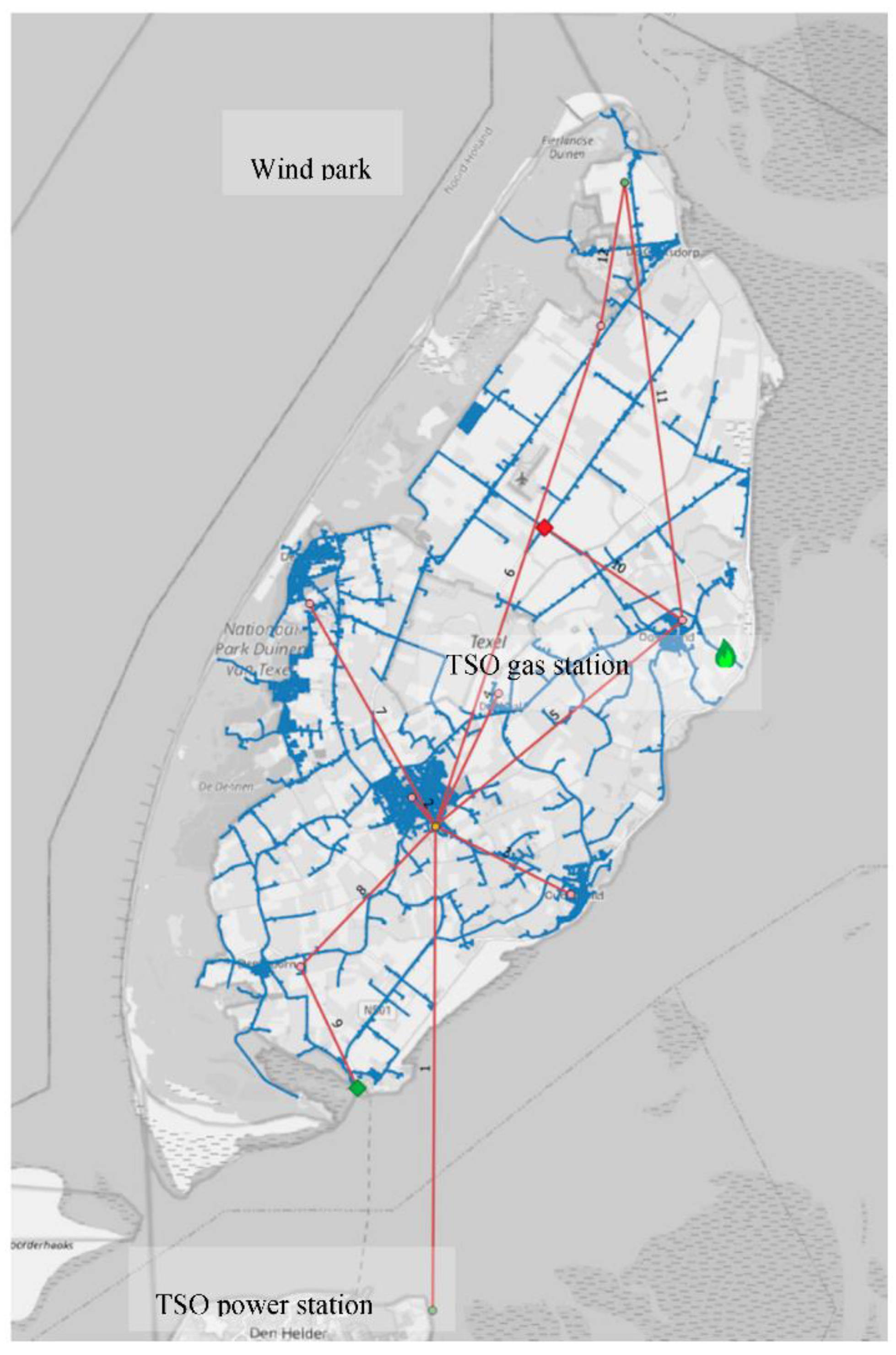
To show the use of hybrid network simulation to analyze control strategies for multicommodity solutions, a simplified version of the island electricity network is coupled to the full-scale gas network as described in the previous section. The simplified electricity network consists of the high voltage supply line for the island and a simplified medium voltage network supplying power to seven geographic regions on the island. The regional demands were derived from the actual DSO supplied data on energy demand, aggregated on demands on zip-code level. An artificial wind park was added to the electricity grid to add local electrical power generation. Interaction between the networks was modeled by adding a P2G unit and a G2P unit to the network. The network is visualized in
Figure 13.
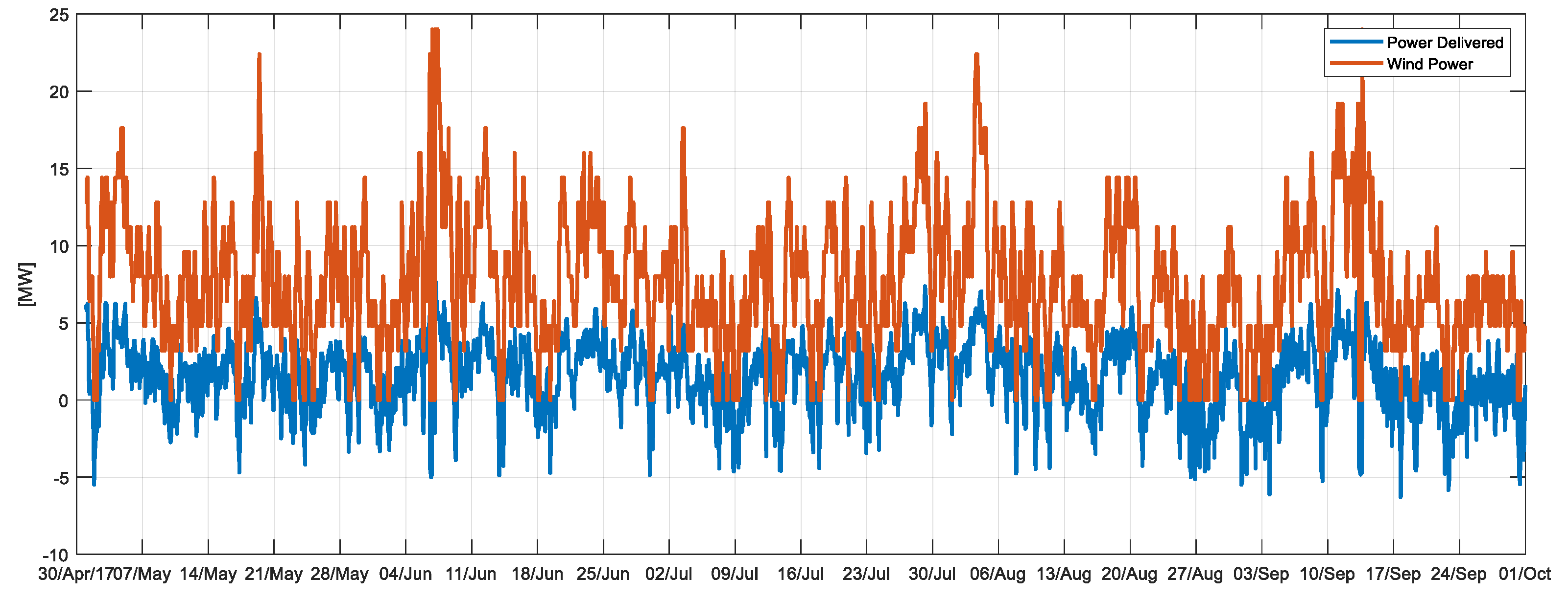
The starting point is a situation where a 24-MW wind park has been positioned in the north part of the island. When we simulated the electricity grid over a period of five months (May–October 2017) using the recorded climate data, the wind park was able to provide sufficient energy to cover 76% of the time the total power demand of the island and energy is exported to the mainland (
Figure 14).
Suppose the island decides to avoid exporting electrical power to the mainland during peak wind power periods, with possible negative pricing, and wants to be more self-supplying. It considers placing a P2G unit on the island and injects produced gas into its gas network. The Transmission System Operator (TSO) gas station operates at local pressure output control and, thus, will reduce gas injection into the gas network if demand decreases. The P2G unit will, thus, indirectly lead to decreased exported power and to a reduction of the import of gas from the high-pressure TSO gas station.
The control scheme for the P2G unit investigated here can be formulated as:
If the wind power production at any moment exceeds expected island power demand, turn on the P2G unit and produce gas with an input power setpoint of 90% of the current expected surplus power;
If the output pressure at the P2G unit exceeds the maximum allowed pressure level, scale back the input power setpoint of the P2G unit;
If the output pressure exceeds the maximum allowed pressure level shut-in the P2G unit.
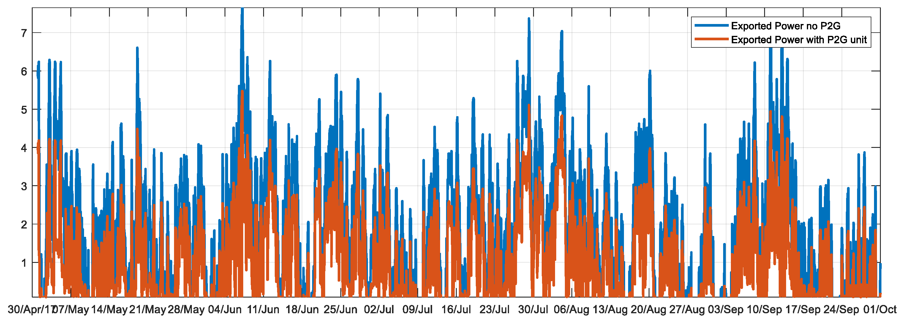
Using this control scheme, the hybrid network is simulated. Results are shown in
Figure 15.
In this test case, random events such as pipe failures and power failures are not taken into account, but only weather variability is considered (taken from a time series of weather station data), leading to variable user demand and to wind power production.
The result of the P2G unit control strategy is that the export of energy [MWh] is reduced by 46%. Total gas import is reduced by 14%. The limited effect of the P2G unit is explained by the KPI GPL_P, which indicates that in total, 39% of the time (mainly during night hours and in summer months), the P2G gas production has to be scaled back, because pressure in the gas network hits maximum limits due to low gas demand. This value is directly determined from the computed time series of the GPL_P. The output pressure -controlled TSO station is in this case incapable of maintaining allowed network pressures in parts of the network. The P2G unit in these situations, therefore, operates at lower capacity or shuts in, and consequently, the surplus electric power is exported.
The performance of the P2G unit can be improved by moving the unit to an optimal location in the gas network, with more downstream gas consumers, or by including gas storage.
4. Conclusions
In this paper, we presented a stochastic method for evaluating the security of supply in integrated electricity and gas networks. The method is applied to a coupled electricity and gas network model to assess the operational performance of hybrid energy distribution networks. The model takes into account user demand (affected by weather) and logic control of supplier and conversion units (such as P2G and G2P).
We proposed a set of KPIs to quantify the impact of events on the security of supply in the hybrid networks and to evaluate the operational performance of energy supplier and conversion units.
The calculated security of supply parameters on a real gas network give insight into the most critical parts of the network w.r.t. gas supply, taking into account physical constraints and the likelihood of events.
Hybrid simulation facilitates control design and performance evaluation of multicommodity solutions in regional networks, including the physical bottlenecks present in the grids.
The simulation model can be used for planning maintenance as well as network reinforcement or phasing out of parts of the network. This requires coupling to predictive models for supply and demand of both gas and electricity.
The quantitative method presented in this paper to assess the security of supply in regional integrated electricity and gas networks determined the operational impact for a given design. Conversely, insights in the critical parts of the networks determined from this method provide input for improved design of the networks.
Together with similar analyses on the robustness of the transmission network level and economic models presented in previous papers, system operators, governments and regulatory bodies may be assisted in increasing the security of supply in the energy infrastructure.
The evaluation of (1) the security of supply using the stochastic method in a hybrid energy network and (2) the impact of varying gas quality under dynamic supply of gas with various compositions on security of supply remains to be studied in future works.
