
Strength Tests of Hardened Cement Slurries for Energy Piles, with the Addition of Graphite and Graphene, in Terms of Increasing the Heat Transfer Efficiency


Abstract
1. Introduction
2. Energy Piles
3. Preparation and Conduct of Research
- q: heat flux flowing through the sample, Wm−2,
- λ: thermal conductivity of the sample, Wm−1K−1,
- dt/dx: temperature gradient on the isotherm flat surface in the sample, Km−1.
4. Research Results and Analysis
- σ: bending/compressive strength of the sample, MPa,
- F: the smallest force exerted by the piston on the sample surface causing bending/compression, kN,
- A: cross-sectional area, on which the piston acts during bending/compression of the sample (for bending, the strength value is calculated for the cross-sectional area A, and for compression, two strength values are calculated for the pressure plate area (compression surface) equal to 1600 mm2), mm2.
5. Conclusions
- Among the slurries tested on a hydraulic press after 28 days, the formula with the 0.1% graphene addition (formula C) turned out to be the one with definitely the best values of bending and compression strength;
- based on the research, it can be concluded that the cement slurry with the 0.1% graphene addition may be used in future field applications during deep foundation works intending to draw energy from the rock mass. Currently, primarily the high price of graphene materials limits the implementation of such a solution to general use. The use of larger than nanopowder graphene structures will presumably have a positive effect on the mechanical strength increase in the piles and the reduction of their thermal resistance;
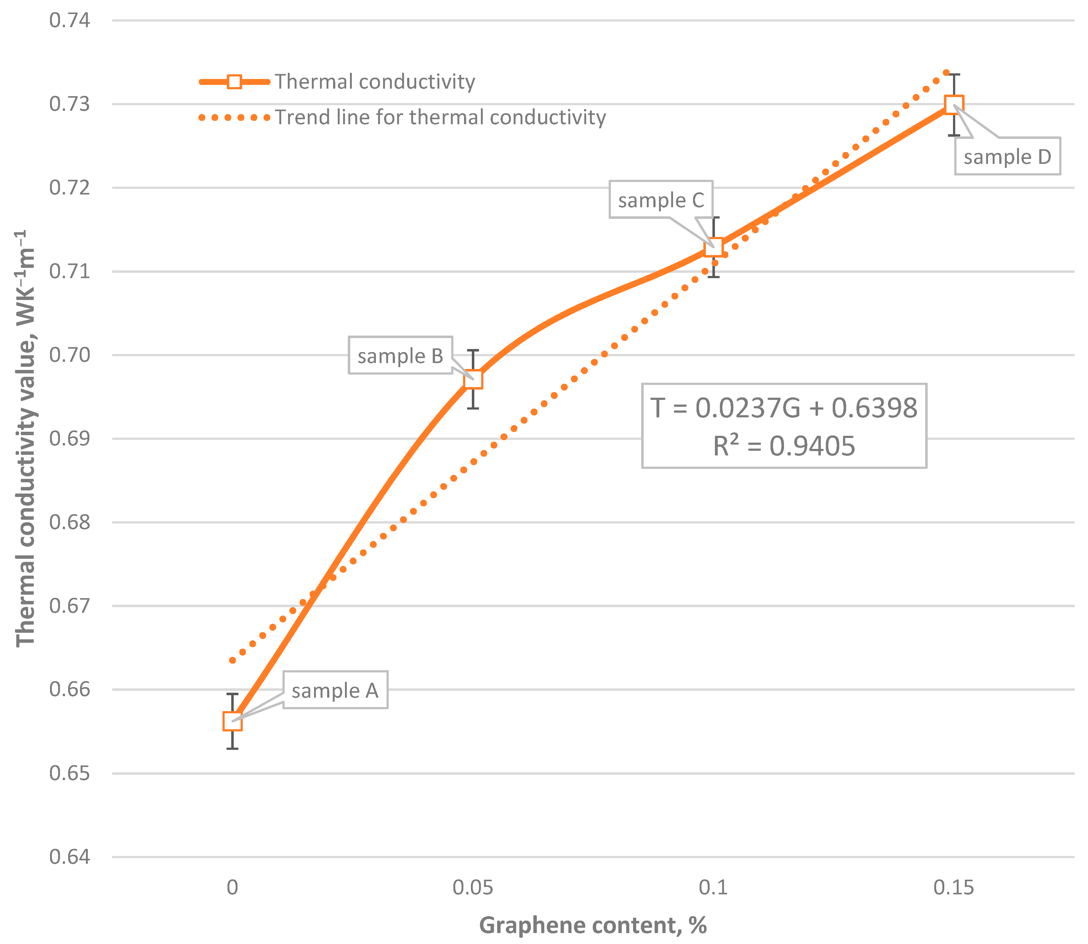
- with the growth of graphene content in the sample, the value of thermal conductivity increases; the highest value of thermal conductivity was observed for sample D;
- despite the highest thermal conductivity value of formula D, it can be concluded that formula C has the best chance of being used in energy piles.
Author Contributions
Funding
Conflicts of Interest
References
- Sapińska-Śliwa, A.; Rosen, M.A.; Gonet, A.; Kowalczyk, J.; Śliwa, T. A New Method Based on Thermal Response Tests for Determining Effective Thermal Conductivity and Borehole Resistivity for Borehole Heat Exchangers. Energies 2019, 12, 1072. [Google Scholar] [CrossRef]
- Crandall, A.C. House Heating with Earth Heat Pump. Electr. World 1946, 126/19, 94–95. [Google Scholar]
- Kemler, E.N. Methods of Earth Heat Recovery for the Heat Pump. Heat. Vent. 1947, 9/1947, 69–72. [Google Scholar]
- Ingersoll, L.R.; Adler, F.T.; Plass, H.J.; Ingersoll, A.C. Theory of Earth Heat Exchangers for the Heat Pump. ASHVE Trans. 1950, 56, 167–188. [Google Scholar]
- Sliwa, T. Wybrane systemy geotermalne w skałach suchych (Chosen geothermal systems in dry rocks). In Proceedings of the Konferencja Naukowa “Aktualny stan i perspektywy rozwoju górnictwa w aspekcie ochrony środowiska” (Conference on Current state and development prospects of mining in the aspect of environmental protection, proceedings), Dnipropetrovsk, Ukraine, 13–14 May 1996; pp. 307–312. [Google Scholar]
- Sliwa, T. Wybrane systemy geotermalne w aspekcie warunków geologicznych (Chosen geotermic systems in aspect of geology). Zeszyty Naukowe AGH Wiertnictwo Nafta Gaz. 1998, 15, 199–208. (In Polish) [Google Scholar]
- Sliwa, T.; Stryczek, S.; Wysogląd, T.; Skakuj, A.; Wiśniowski, R.; Sapińska-Śliwa, A.; Bieda, A.; Kowalski, T. Wpływ grafitu i diatomitu na parametry wytrzymałościowe stwardniałych zaczynów cementowych (Impact of graphite and diatomite on the strength parameters of hardened cement slurries). Przem. Chem. 2017, 96, 960–963. (In Polish) [Google Scholar]
- Sapińska-Śliwa, A. Efektywność Pozyskiwania ciepła z Górotworu w Aspekcie Sposobu Udostępniania Otworami Wiertniczymi (Effectiveness of Heat Recovery from Rock Mass in the Context of the Production Method by Means of Boreholes); Rozprawy Monografie Akademia Górniczo-Hutnicza im. Stanisława Staszica w Krakowie, 2019, no. 364; Wydawnictwa AGH UST: Kraków, Poland, 2019; p. 320. (In Polish) [Google Scholar]
- Sliwa, T.; Sapińska-Śliwa, A.; Knez, D.; Bieda, A.; Kowalski, T.; Złotkowski, A. Borehole Heat Exchangers, Production and Storage of Heat in the Rock Mass, Laboratory of Geoenergetics book series vol. 2, 1st ed.; Oil and Gas Foundation: Krakow, Poland, 2016; p. 177. [Google Scholar]
- Sliwa, T.; Kotyza, J. Application of Existing Wells as Ground Heat Source for Heat Pumps in Poland. Appl. Energy 2003, 74, 3–8. [Google Scholar] [CrossRef]
- Sliwa, T.; Rosen, M.A.; Jezuit, Z. Use of Oil Boreholes in the Carpathians in Geoenergetic Systems: Historical and Conceptual Review. Res. J. Environ. Sci. 2014, 8, 231–242. [Google Scholar] [CrossRef]
- Sliwa, T.; Rosen, M.A. Efficiency Analysis of Borehole Heat Exchangers as Grout Varies Via Thermal Response Test Simulations. Geothermics 2017, 69, 132–138. [Google Scholar] [CrossRef]
- Mayfield, M. ICT in BSF Environmental Challenges an Engineer’s View (presentation ppt). Available online: https://www.partnershipsforschools.org.uk/index.html (accessed on 15 January 2019).
- 14. Vasilescu, A-R. Design and Execution of Energy Piles: Validation by In-Situ and Laboratory Experiments. Doctorate Thesis, L’École Centrale de Nantes, Nantes, France, 5 December 2019.
- Sliwa, T.; Rosen, M.A. Natural and Artificial Methods for Regeneration of Heat Resources for Borehole Heat Exchangers to Enhance the Sustainability of Underground Thermal Storages: A Review. Sustainability 2015, 7, 13104–13125. [Google Scholar] [CrossRef]
- Grabowski, Z.; Pisarczyk, S.; Obrycki, M. Fundamentowanie, 5th ed.; Oficyna Wydawnicza Politechniki Warszawskiej: Warszawa, Poland, 2005; p. 228. (In Polish) [Google Scholar]
- Stryczek, S.; Gonet, A. Geoinżynieria, 1st ed.; Wydawnictwo Instytutu Gospodarki Surowcami Mineralnymi i Energią PAN: Kraków, Poland, 2000; p. 153. (In Polish) [Google Scholar]
- Sliwa, T.; Gonet, A.; Ostrowska, K. Możliwości pozyskania ciepła z ośrodka gruntowego za pośrednictwem pali nośnych (Possibility of heat extracting from ground by foundation piles). Technika Poszukiwań Geologicznych. Geotermia, Zrównoważony Rozwój 2007, 46, 85–89. (In Polish) [Google Scholar]
- Gonet, A.; Sliwa, T.; Stryczek, S.; Sapińska-Śliwa, A.; Jaszczur, M.; Pająk, L.; Złotkowski, A. Metodyka Identyfikacji Potencjału Cieplnego Górotworu Wraz z Technologią Wykonania i Eksploatacji Otworowych Wymienników Ciepła, 1st ed.; Wydawnictwa AGH: Krakow, Poland, 2011; p. 440. (In Polish) [Google Scholar]
- Schröder, B.; Hanschke, T. Energiepfhähle-umweltfreundliches Heizen und Kühlen mit geothermisch aktivierten Stahlbetonfertigpfählen. Bautechnik 2003, 80, 925–927. [Google Scholar]
- Brandl, H. Energy Foundations and Other Thermo Active Ground Structures. Geotechnique 2006, 56, 81–122. [Google Scholar] [CrossRef]
- Amis, T.; Loveridge, F. Energy Piles and Other Thermal Foundations for GSHP - Developments in UK Practice and Research. REHVA J. 2014, 32–35. [Google Scholar]
- Desmedt, J.; Hoes, H. Case Study of a BTES and Energy Piles Application for a Belgian Hospital. In Proceedings of the Proceedings ECOSTOCK 2006, New Jersey, US, The Richard Stockton College of New Jersey. 2006. Available online: http://citeseerx.ist.psu.edu/viewdoc/download?doi=10.1.1.507.2234&rep=rep1&type=pdf (accessed on 10 March 2020).
- Koene, F.G.H.; van Helden, W.G.J.; Romer, J.C. Energy Piles as Cost Effective Ground Heat Exchangers. In Proceedings of the Proceedings TERRASTOCK 2000, Stuttgart, Germany, 28 August–1 September 2000; pp. 227–232. [Google Scholar]
- Pahud, D.; Hubbuch, M. Measured Thermal Performance of the Energy Pile System of the Dock Midfield of Zurich Airport. In Proceedings of the Proceedings European Geothermal Congress 2007, Unterhaching, Germany, 30 May–1 June 2007; Available online: https://www.geothermal-energy.org/pdf/IGAstandard/EGC/2007/195.pdf (accessed on 10 March 2020).
- Poulsen, S.E.; Alberdi-Pagola, M.A.; Cerra, D.; Magrini, A. An Experimental and Numerical Case Study of Passive Building Cooling with Foundation Pile Heat Exchangers in Denmark. Energies 2019, 12, 2697. [Google Scholar] [CrossRef]
- Lennon, D.J.; Watt, E.; Suckling, T.P. Energy Piles in Scotland. In Proceedings of the Fifth International Conference Deep Found Bored Auger Piles, Frankfurt, Germany, 15 May 2009. [Google Scholar]
- Fadajev, J.; Simson, R.; Kurnitski, J.; Haghighat, F. A Review on Energy Piles Design, Sizing and Modelling. Energy 2017, 1221, 390–407. [Google Scholar] [CrossRef]
- Sung, C.; Park, S.; Lee, S.; Oh, K.; Choi, H. Thermo-Mechanical Behavior of Cast-In-Place Energy Piles. Energy 2018, 161, 920–938. [Google Scholar] [CrossRef]
- Park, S.; Lee, D.; Lee, S.; Chauchois, A.; Choi, H. Experimental and Numerical Analysis on Thermal Performance of Large-Diameter Cast-In-Place Energy Pile Constructed in Soft Ground. Energy 2017, 118, 297–311. [Google Scholar] [CrossRef]
- Sani, A.K.; Singh, R.M.; Amis, T.; Cavarretta, I. A Review on the Performance of Geothermal Energy Pile Foundation, Its Design Process and Applications. Renew. Sustain. Energy Rev. 2019, 106, 54–78. [Google Scholar] [CrossRef]
- Zhao, Q.; Chen, B.; Tian, M.; Liu, F. Investigation on the Thermal Behavior of Energy Piles and Borehole Heat Exchangers: A Case Study. Energy 2018, 1621, 787–797. [Google Scholar] [CrossRef]
- Moon, C.E.; Choi, J.M. Heating Performance Characteristics of the Ground Source Heat Pump System with Energy-Piles and Energy-Slabs. Energy 2015, 811, 27–32. [Google Scholar] [CrossRef]
- Cecinato, F.; Loveridge, F.A. Influences on the Thermal Efficiency of Energy Piles. Energy 2015, 82, 1021–1033. [Google Scholar] [CrossRef]
- Tsubaki, K.; Mitsutake, Y. Performance of Ground-Source Heat Exchangers Using Short Residential Foundation Piles. Energy 2016, 1041, 229–236. [Google Scholar] [CrossRef]
- Rychlewski, P.; Jurasz, W.; Sierant, J. Fundamenty palowe–jako elementy instalacji pozyskującej energię cieplną z gruntu w instalacjach pomp ciepła—Termopale. Inżynier budownictwa 2014, 113, 88–94. (In Polish) [Google Scholar]
- Park, S.; Lee, D.; Choi, H.J.; Jung, K.; Choi, H. Relative Constructability and Thermal Performance of Cast-In-Place Concrete Energy Pile: Coil-Type GHEX (Ground Heat Exchanger). Energy 2015, 811, 56–66. [Google Scholar] [CrossRef]
- Sliwa, T.; Sojczyńska, A.; Rosen, M.A.; Kowalski, T. Evaluation of Temperature Profiling Quality in Determining Energy Efficiencies of Borehole Heat Exchangers. Geothermics 2019, 78, 129–137. [Google Scholar] [CrossRef]
- Mousa, M.M.; Bayom, A.M.; Saghir, M.Z. Experimental and Numerical Study on Energy Piles with Phase Change Materials. Energies 2020, 13, 4699. [Google Scholar] [CrossRef]
- Lyu, W.; Pu, H.; Chen, J. Thermal Performance of an Energy Pile Group with a Deeply Penetrating U-Shaped Heat Exchanger. Energies 2020, 13, 5822. [Google Scholar] [CrossRef]
- Jalaluddin; Miyara, A.; Tsubaki, K.; Inoue, S.; Yoshida, K. Experimental Study of Several Types of Ground Heat Exchanger Using a Steel Pile Foundation. Renew. Energy 2011, 36, 764–771. [Google Scholar]
- Zarrella, A.; DeCarli, M.; Galgaro, A. Thermal Performance of Two Types of Energy Foundation Pile: Helical Pipe and Triple U-tube. Appl. Therm. Eng. 2013, 61, 301–310. [Google Scholar] [CrossRef]
- Bezyan, B.; Porkhial, S.; Mehrizi, A.A. 3-D Simulation of Heat Transfer Rate in Geothermal Pile-Foundation Heat Exchangers with Spiral Pipe Configuration. Appl. Therm. Eng. 2015, 87, 655–668. [Google Scholar] [CrossRef]
- Zhao, Q.; Liu, F.; Liu, C.; Tian, M.; Chen, B. Influence of Spiral Pitch on the Thermal Behaviors of Energy Piles with Spiral-Tube Heat Exchanger. Appl. Therm. Eng. 2017, 125, 1280–1290. [Google Scholar] [CrossRef]
- Saeidi, R.; Noorollahi, Y.; Esfahanian, V. Numerical Simulation of a Novel Spiral Type Ground Heat Exchanger for Enhancing Heat Transfer Performance of Geothermal Heat Pump. Energy Convers. Manag. 2018, 168, 296–307. [Google Scholar] [CrossRef]
- Cui, P.; Li, X.; Man, Y.; Fang, Z. Heat Transfer Analysis of Pile Geothermal Heat Exchangers with Spiral Coils. Applied Energy 2011, 88, 4113–4119. [Google Scholar] [CrossRef]
- Huang, G.; Yang, X.; Liu, Y.; Zhuang, C.; Zhang, H.; Lu, J. A Novel Truncated Cone Helix Energy Pile: Modelling and Investigations of Thermal Performance. Energy Build. 2018, 158, 1241–1256. [Google Scholar] [CrossRef]
- Go, G.H.; Lee, S.R.; Kang, H.B.; Yoon, S.; Kim, M.J. A Novel Hybrid Design Algorithm for Spiral Coil Energy Piles that Considers Groundwater Advection. Appl. Therm. Eng. 2015, 78, 196–208. [Google Scholar] [CrossRef]
- Yoon, S.; Lee, S.R.; Xue, J.; Zosseder, K.; Go, G.H.; Park, H. Evaluation of the Thermal Efficiency and a Costanalysis of Different Types of Ground Heat Exchangers in Energy Piles. Energy Convers. Manag. 2015, 105, 393–402. [Google Scholar] [CrossRef]
- Zhao, Q.; Chen, B.; Liub, B. Study on the Thermal Performance of Several Types of Energy Pile Ground Heat Exchangers: U-Shaped, W-Shaped and Spiral-Shaped. Energy Build. 2016, 133, 335–344. [Google Scholar] [CrossRef]
- Sliwa, T.; Nowosiad, T.; Vytyaz, O.; Sapińska-Śliwa, A. Study on the Efficiency of Deep Borehole Heat Exchangers. SOCAR Proc. 2016, 2, 29–42. [Google Scholar] [CrossRef]
- Olgun, C.G. Design Considerations of Energy Piles. In Proceedings of the International Bridge Conference, Pittsburgh, PA, UAS, 7 June 2011. [Google Scholar]
- Suckling, T. Geothermal Energy and Energy Piles, Stent Foundations Ltd., UK. Personal communication, 2008. [Google Scholar]
- Maca, N.; Ryżyński, G. Termopale–termoaktywne elementy posadowień obiektów budowlanych (TITAN Polska). XI Międzynarodowe Targi Geologiczne GEO-EKO-TECH. 8–9 May 2013. Available online: https://www.pgi.gov.pl/docman-tree/wydarzenia/targi/1765-geologia-2013-termopale/file.html (accessed on 22 February 2021). (In Polish)
- Skanska. Available online: www.skanska.co.uk (accessed on 15 January 2019).
- Bourne-Webb, P. Observed Response of Energy Geostructures. In Energy Geostructures Innovation in Underground Engineering; Laloui, L., Di Donna, A., Eds.; Wiley: London, UK, 2013; pp. 45–67. [Google Scholar]
- Dyrektywa Parlamentu Europejskiego i Rady 2010/31/UE z dnia 19 maja 2010 roku w sprawie charakterystyki energetycznej budynków, Dziennik Urzędowy Unii Europejskiej, L 153/13, 18.6.2010. Available online: https://eur-lex.europa.eu/legal-content/PL/TXT/PDF/?uri=CELEX:32010L0031&from=EL (accessed on 23 January 2019). (In Polish).
- Ferrantelli, A.; Fadejev, J.; Kurnitski, J. Energy Pile Field Simulation in Large Buildings: Validation of Surface Boundary Assumptions. Energies 2019, 12, 770. [Google Scholar] [CrossRef]
- Alberdi-Pagola, M.; Poulsen, S.E.; Jensen, R.L.; Madsen, S. Thermal Design Method for Multiple Precast Energy Piles. Geothermics 2019, 78, 201–210. [Google Scholar] [CrossRef]
- Caulk, R.; Ghazanfari, E.; McCartney, J.S. Parameterization of a Calibrated Geothermal Energy Pile Model. Geomech. Energy Environ. 2016, 5, 1–15. [Google Scholar] [CrossRef]
- Dupray, F.; Laloui, L.; Kazangba, A. Numerical Analysis of Seasonal Heat Storage in an Energy Pile Foundation. Comput. Geotech. 2014, 55, 67–77. [Google Scholar] [CrossRef]
- Loria, A.F.R.; Vadrot, A.; Laloui, L. Analysis of the Vertical Displacement of Energy Pile Groups. Geomech. Energy Environ. 2018, 16, 1–14. [Google Scholar] [CrossRef]
- Cristodoulides, P.; Vieira, A.; Lenart, S.; Maranha, J.; Vidmar, G.; Popov, R.; Georgiev, A.; Aresti, L.; Florides, G. Reviewing the Modeling Aspects and Practices of Shallow Geothermal Energy Systems. Energies 2020, 13, 4273. [Google Scholar] [CrossRef]
- Park, H.; Lee, S.R.; Yoon, S.; Choi, J.C. Evaluation of Thermal Response and Performance of PHC Energy Pile: Field Experiments and Numerical Simulation. Appl. Energy 2013, 103, 12–24. [Google Scholar] [CrossRef]
- Laloui, L.; Sutman, M. Experimental Investigation of Energy Piles: From Laboratory to Field Testing. Geomech. Energy Environ. 2020. [Google Scholar] [CrossRef]
- Sliwa, T.; Gonet, A. Theoretical Model of Borehole Heat Exchanger. J. Energy Resour. Technol. 2005, 127, 142–148. [Google Scholar] [CrossRef]
- Al-Khoury, R.; Kölbel, T.; Schramedei, R. Efficient Numerical Modeling of Borehole Heat Exchangers. Comput. Geosci. 2010, 36, 1301–1315. [Google Scholar] [CrossRef]
- Bauer, D.; Heidemann, W.; Diersch, H.J. Transient 3D Analysis of Borehole Heat Exchanger Modeling. Geothermics 2011, 40, 250–260. [Google Scholar] [CrossRef]
- Sliwa, T.; Gołaś, A.; Wołoszyn, J.; Gonet, A. Numerical Model of Borehole Heat Exchanger in ANSYS CFX Software. Arch. Min. Sci. 2012, 57, 375–390. [Google Scholar]
- Fadejev, J.; Kurnitski, J. Geothermal Energy Piles and Boreholes Design with Heat Pump in a Whole Building Simulation Software. Energy Build. 2015, 106, 23–34. [Google Scholar] [CrossRef]
- Loveridge, F.A.; Olgun, G.; Brettmann, T.; Powrie., W. Group Thermal Response Testing for Energy Piles. In Proceedings of the XVI European Conference for Soil Mechanics and Geotechnical Engineering, Edinburgh, UK, 13–17 September 2015; pp. 2595–2600. [Google Scholar]
- Sapińska-Śliwa, A.; Sliwa, T.; Twardowski, K.; Szymski, K.; Gonet, A.; Żuk, P. Method of Averaging the Effective Thermal Conductivity Based on Thermal Response Tests of Borehole Heat Exchangers. Energies 2020, 13, 3737. [Google Scholar] [CrossRef]
- Gehlin, S.; Eklof, C. A Mobile Equipment for Thermal Response Test. Master’s Thesis, Luleå University of Technology, Luleå, Sweden, January 1996. [Google Scholar]
- Spitler, J.D.; Gehlin, S.E.A. Thermal Response Testing for Ground Source Heat Pump Systems—An Historical Review. Renew. Sustain. Energy Rev. 2015, 50, 1125–1137. [Google Scholar] [CrossRef]
- Acuña, J.; Mogensen, P.; Palm, B. Distributed Thermal Response Test on a U-Pipe Borehole Heat Exchanger. In Proceedings of the Effstock 2009, 11th International Conference on Thermal Energy Storage, Stockholm, Sweden, 14–17 June 2009. [Google Scholar]
- Banks, D.; Withers, J.; Freeborn, R. An Overview of the Results of In-Situ Thermal Response Testing in the UK. In Proceedings of the 11th International Conference on Thermal Energy Storage for Efficiency and Sustainability, Stockholm, Sweden, 14–17 June 2009. [Google Scholar]
- Jensen-Page, L.; Loveridge, F.; Narsillio, G.A. Thermal Response Testing of Large Diameter Energy Piles. Energies 2019, 12, 2700. [Google Scholar] [CrossRef]
- Ozudogru, T.; Brettmann, T.; Olgun, G.; Martin, J.; Senol, A. Thermal Conductivity Testing of Energy Piles: Field Testing and Numerical Modeling. In Proceedings of the Geo-Congress, Oakland, CA, USA, 25–29 March 2012. [Google Scholar]
- Franco, A.; Moffat, R.; Toledo, M.; Herrera, P. Numerical Sensitivity Analysis of Thermal Response Tests (TRT) in Energy Piles. Renew. Energy 2016, 86, 985–992. [Google Scholar] [CrossRef]
- Hu, P.; Zha, J.; Lei, F.; Zhu, N.; Wu, T. A Composite Cylindrical Model and Its Application in Analysis of Thermal Response and Performance for Energy Pile. Energy Build. 2014, 84, 324–332. [Google Scholar] [CrossRef]
- Fossa, M.; Priarone, A.; Silenzi, F. Superposition of the Single Point Source Solution to Generate Temperature Response Factors for Geothermal Piles. Renew. Energy 2020, 145, 805–813. [Google Scholar] [CrossRef]
- Giergiczny, Z.; Batóg, M.; Dziuk, D.; Golda, A.; Grabski, J.; Kaszuba, S.; Sokołowski, M.; Synowiec, K.; Szuba, J.; Wąsik, M. Górażdże Cement, Kruszywa Beton - Rodzaje, Właściwości, Zastosowanie; Górażdze: Chorula, Poland, 2016; p. 399. (In Polish) [Google Scholar]
- Sapińska-Śliwa, A.; Sliwa, T.; Wiśniowski, R. Grafit i diatomit jako dodatki do zaczynów uszczelniających otwory w geotermii (Graphite and diatomite as additives for grouts for boreholes in geothermics). Przemysł Chemiczny 2017, 96, 1723–1725. (In Polish) [Google Scholar]
- API. Specification for Materials and Testing for well Cements; API SPEC 10A; American Petroleum Institute: Washington, DC, USA, December 2010. [Google Scholar]
- Polski Komitet Normalizacyjny, Przemysł Naftowy i Gazowniczy—Cementy i Materiały do Cementowania Otworów Wiertniczych—Część 2: Badania Cementów Wiertniczych; PN-EN ISO 10426-2:2006; Polski Komitet Normalizacyjny: Warszawa, Poland, 18 May 2006. (In Polish)
- Polski Komitet Normalizacyjny. In Cementy i Zaczyny Cementowe do Cementowania w Otworach Wiertniczych; PN-85-G-02320; Polski Komitet Normalizacyjny: Warszawa, Poland, 1985. (In Polish)
- FOX 50 instrument manual, LaserComp–TA Instruments, CD Version 2018.
- Polski Komitet Normalizacyjny. In Metody badania cementu—Część 1: Oznaczanie wytrzymałości; PN-EN 196-1:2016-07; Polski Komitet Normalizacyjny: Warszawa, Poland, 12 January 2018. (In Polish)
- Bai, S.; Jiang, L.; Xu, N.; Jin, M.; Jiang, S. Enhancement of Mechanical and Electrical Properties of Graphene/Cement Composite due to Improved Dispersion of Graphene by Addition of Silica Fume. Constr. Build. Mater. 2018, 164, 433–441. [Google Scholar] [CrossRef]


| w/c = 1.0 | ||||||
|---|---|---|---|---|---|---|
| Sample Name | A | B | C | D | ||
| Graphene percentage | % | 0 | 0.05 | 0.1 | 0.15 | |
| Water | g | 1500 | 1500 | 1500 | 1500 | |
| Solid ingredients | Graphene | g | 0 | 0.75 | 1.5 | 2.25 |
| Graphite | g | 300 | 300 | 300 | 300 | |
| Cement | g | 1500 | 1500 | 1500 | 1500 | |
| PSP-042 | g | 6 | 6 | 6 | 6 | |
| Sum | g | 1806 | 1806.75 | 1807.5 | 1808.25 | |
| Sample | A | ||
|---|---|---|---|
| w/c | 1.0 | 1.0 | 1.0 |
| cement, g | 1500 | 1500 | 1500 |
| water, g | 1500 | 1500 | 1500 |
| graphite, g | 300 | 300 | 300 |
| graphene 12 nm, g | 0 | 0 | 0 |
| PSP-042, g | 6 | 6 | 6 |
| sample dimensions, cm | 4 × 3.96 × 16 | 4 × 4.00 × 16 | 4 × 4.00 × 16 |
| cross-sectional area of the crushed sample, A, mm2 | 422.4 | 426.7 | 426.7 |
| minimum bending force, Fz, kN | 1.16 | 1.116 | 0.987 |
| flexural strength, σz, MPa | 2.753 | 2.615 | 2.312 |
| minimum compressive force of the 1st half, Fs1, kN | 11.007 | 10.564 | 7.771 |
| minimum compressive force of the 2nd half, Fs2, kN | 10.656 | 8.942 | 7.393 |
| compressive strength of the 1st half (A1), σs1, MPa | 6.949 | 6.603 | 4.857 |
| compressive strength of the 2nd half (A2), σs2, MPa | 6.727 | 5.589 | 4.621 |
| average bending strength, avr. σz, MPa | 2.560 | ||
| standard deviation for bending strength, MPa | 0.184 | ||
| average compressive strength, avr. σs, MPa | 5.891 | ||
| standard deviation for the compressive strength, MPa | 0.922 | ||
| Sample | B | ||
|---|---|---|---|
| w/c | 1.0 | 1.0 | 1.0 |
| cement, g | 1500 | 1500 | 1500 |
| water, g | 1500 | 1500 | 1500 |
| graphite, g | 300 | 300 | 300 |
| graphene 12 nm, g | 0.75 | 0.75 | 0.75 |
| PSP-042, g | 6 | 6 | 6 |
| sample dimensions, cm | 4 × 3.9 × 16 | 4 × 3.96 × 16 | 4 × 4.04 × 16 |
| cross-sectional area of the crushed sample, A, mm2 | 416.0 | 422.4 | 430.9 |
| minimum bending force, Fz, kN | 1.119 | 1.100 | 1.042 |
| flexural strength, σz, MPa | 2.689 | 2.605 | 2.419 |
| minimum compressive force of the 1st half, Fs1, kN | 9.486 | 9.043 | 9.283 |
| minimum compressive force of the 2nd half, Fs2, kN | 8.499 | 9.292 | 8.462 |
| compressive strength of the 1st half (A1), σs1, MPa | 6.081 | 5.709 | 5.744 |
| compressive strength of the 2nd half (A2), σs2, MPa | 5.448 | 5.866 | 5.237 |
| average bending strength, avr. σz, MPa | 2.571 | ||
| standard deviation for bending strength, MPa | 0.113 | ||
| average compressive strength, avr. σs, MPa | 5.681 | ||
| standard deviation for the compressive strength, MPa | 0.274 | ||
| Sample | C | ||
|---|---|---|---|
| w/c | 1.0 | 1.0 | 1.0 |
| cement, g | 1500 | 1500 | 1500 |
| water, g | 1500 | 1500 | 1500 |
| graphite, g | 300 | 300 | 300 |
| graphene 12 nm, g | 1.5 | 1.5 | 1.5 |
| PSP-042, g | 6 | 6 | 6 |
| sample dimensions, cm | 4 × 3.92 × 16 | 4 × 3.86 × 16 | 4 × 3.97 × 16 |
| cross-sectional area of the crushed sample, A, mm2 | 418.1 | 411.7 | 423.5 |
| minimum bending force, Fz, kN | 1.544 | 1.223 | 1.697 |
| flexural strength, σz, MPa | 3.692 | 2.971 | 4.008 |
| minimum compressive force of the 1st half, Fs1, kN | 15.127 | 14.076 | 14.657 |
| minimum compressive force of the 2nd half, Fs2, kN | 15.726 | 13.92 | 15.183 |
| compressive strength of the 1st half (A1), σs1, MPa | 9.647 | 9.117 | 9.230 |
| compressive strength of the 2nd half (A2), σs2, MPa | 10.03 | 9.015 | 9.561 |
| average bending strength, avr. σz, MPa | 3.557 | ||
| standard deviation for bending strength, MPa | 0.434 | ||
| average compressive strength, avr. σs, MPa | 9.433 | ||
| standard deviation for the compressive strength, MPa | 0.350 | ||
| Sample | D | ||
|---|---|---|---|
| w/c | 1.0 | 1.0 | 1.0 |
| cement, g | 1500 | 1500 | 1500 |
| water, g | 1500 | 1500 | 1500 |
| graphite, g | 300 | 300 | 300 |
| graphene 12 nm, g | 2.25 | 2.25 | 2.25 |
| PSP-042, g | 6 | 6 | 6 |
| sample dimensions, cm | 4 × 3.77 × 16 | 4 × 3.76 × 16 | 4 × 3.82 × 16 |
| cross-sectional area of the crushed sample, A, mm2 | 402.1 | 401.1 | 407.5 |
| minimum bending force, Fz, kN | 1.202 | 1.071 | 0.884 |
| flexural strength, σz, MPa | 2.989 | 2.671 | 2.170 |
| minimum compressive force of the 1st half, Fs1, kN | 10.306 | 10.011 | 8.886 |
| minimum compressive force of the 2nd half, Fs2, kN | 9.937 | 9.624 | 8.868 |
| compressive strength of the 1st half (A1), σs1, MPa | 6.834 | 6.656 | 5.816 |
| compressive strength of the 2nd half (A2), σs2, MPa | 6.59 | 6.399 | 5.804 |
| average bending strength, avr. σz, MPa | 2.610 | ||
| standard deviation for bending strength, MPa | 0.337 | ||
| average compressive strength, avr. σs, MPa | 6.350 | ||
| standard deviation for the compressive strength, MPa | 0.402 | ||
| w/c = 1.0 | |||||
|---|---|---|---|---|---|
| Sample Name | A | B | C | D | |
| w/c | 1.0 | 1.0 | 1.0 | 1.0 | |
| cement | g | 1500 | 1500 | 1500 | 1500 |
| water | g | 1500 | 1500 | 1500 | 1500 |
| graphite, | g | 300 | 300 | 300 | 300 |
| graphene 12 nm | g | 0 | 0.75 | 1.5 | 2.25 |
| PSP-042 | g | 6 | 6 | 6 | 6 |
| thermal conductivity measurements: | |||||
| no. 1 | WK−1m−1 | 0.6458 | 0.6952 | 0.7219 | 0.7314 |
| no. 2 | WK−1m−1 | 0.6566 | 0.6976 | 0.7056 | 0.7412 |
| no. 3 | WK−1m−1 | 0.6638 | 0.6862 | 0.7158 | 0.7292 |
| no. 4 | WK−1m−1 | 0.6517 | 0.7099 | 0.7216 | 0.7195 |
| no. 5 | WK−1m−1 | 0.6592 | 0.7198 | 0.7159 | 0.7300 |
| no. 6 | WK−1m−1 | 0.6700 | 0.6899 | 0.7062 | 0.7241 |
| no. 7 | WK−1m−1 | 0.6589 | 0.6903 | 0.7099 | 0.7368 |
| no. 8 | WK−1m−1 | 0.6432 | 0.6952 | 0.7004 | 0.7227 |
| no. 9 | WK−1m−1 | 0.6602 | 0.6999 | 0.7159 | 0.7285 |
| no. 10 | WK−1m−1 | 0.6521 | 0.6870 | 0.7158 | 0.7359 |
| average thermal conductivity | WK−1m−1 | 0.6562 | 0.6971 | 0.7129 | 0.7299 |
| standard deviation thermal conductivity | WK−1m−1 | 0.0077 | 0.0101 | 0.0067 | 0.0064 |
Publisher’s Note: MDPI stays neutral with regard to jurisdictional claims in published maps and institutional affiliations. |
© 2021 by the authors. Licensee MDPI, Basel, Switzerland. This article is an open access article distributed under the terms and conditions of the Creative Commons Attribution (CC BY) license (http://creativecommons.org/licenses/by/4.0/).
Share and Cite
Sliwa, T.; Sapińska-Śliwa, A.; Wysogląd, T.; Kowalski, T.; Konopka, I. Strength Tests of Hardened Cement Slurries for Energy Piles, with the Addition of Graphite and Graphene, in Terms of Increasing the Heat Transfer Efficiency. Energies 2021, 14, 1190. https://doi.org/10.3390/en14041190
Sliwa T, Sapińska-Śliwa A, Wysogląd T, Kowalski T, Konopka I. Strength Tests of Hardened Cement Slurries for Energy Piles, with the Addition of Graphite and Graphene, in Terms of Increasing the Heat Transfer Efficiency. Energies. 2021; 14(4):1190. https://doi.org/10.3390/en14041190
Chicago/Turabian StyleSliwa, Tomasz, Aneta Sapińska-Śliwa, Tomasz Wysogląd, Tomasz Kowalski, and Izabela Konopka. 2021. "Strength Tests of Hardened Cement Slurries for Energy Piles, with the Addition of Graphite and Graphene, in Terms of Increasing the Heat Transfer Efficiency" Energies 14, no. 4: 1190. https://doi.org/10.3390/en14041190
APA StyleSliwa, T., Sapińska-Śliwa, A., Wysogląd, T., Kowalski, T., & Konopka, I. (2021). Strength Tests of Hardened Cement Slurries for Energy Piles, with the Addition of Graphite and Graphene, in Terms of Increasing the Heat Transfer Efficiency. Energies, 14(4), 1190. https://doi.org/10.3390/en14041190