1. Introduction
One of the methods of storing and accumulating energy is compressing gases, most often air. Compressed air engines are machines which use the energy of compressed air. The basic advantage of compressed air engines is their relatively small mass in relation to their power at relatively high permissible overloads. Even though there are many designs of compressed air engines, there are far fewer low-speed engines [
1,
2,
3]. The application of high-speed compressed air engines to drive machines and equipment often requires the application of speed reduction gears. Thus, it is appropriate to draw attention to the design of low-speed compressed air engines.
The history of construction solutions for pneumatic motors dates back to the 17th century. The first pneumatic railway was built in 1678. The most dynamic development of pneumatic motors began with the invention of the Polish engineer, Ludwik Mękalski. In the year 1870, Mękalski built a compressed air piston engine which was used to power locomotives in mines and drive trams in French cities, such as Vichy, Nantes or San-Quentino [
4]. The principle of its operation was based on the application of the check valve, the opening of which was activated by a working piston (
Figure 1a). After the valve opened, the compressed air was pumped into the cylinder under high pressure, and from that moment the work cycle began (
Figure 1b). The piston would move downwards under the force of expanding air. In the final phase of piston movement, the outlet channel, through which the excess air escaped, would open (
Figure 1c). The second cycle consisted of the piston returning to the upper return point, where the next working cycle would begin.
The history of the application of air compressed engines to drive vehicles is, however, much longer. The system of dynamic tank pumping during the braking of vehicles, developed in 1892 by Robert Hardie [
5,
6], was an important invention. It was based on inverting the engine work to compressor work during the braking. Thanks to that, some decompressed air was recovered and re-compressed. One of the last pre-war achievements in the field was the design of Johannes Wardenier, which, according to the reports, was supposed to be the first engine not requiring liquid fuel [
7]. Currently, solutions involving low-speed engines for vehicles are still being developed [
8].
In recent decades, increasing attention has been paid to the impact of various industry branches on the natural environment [
9,
10]. Therefore, the ecological factor is becoming increasingly important [
11,
12]. The combustion of fossil fuels is one of the main causes of environmental pollution [
13,
14]. Environmentally safe and emission-free vehicles include electric vehicles; they, however, have a disadvantage—their batteries contain toxic elements which may expel toxic fumes [
15,
16]. Thus, compressed air engines are also within the area of interest. In 1991, Guy Nègre et al. developed a double-energy engine, powered by petrol and compressed air [
17]. Moteur Development International (MDI) developed a compressed air vehicle, E. Volution [
18]. The vehicle is equipped with a 300-litre tank for compressed air, which allows you to travel the distance of 200 km at a speed of 96 kmph. The vehicle is charged at a high-pressure air charging station. Another interesting area of research on the use of renewable sources of power are studies conducted by the University of Northern Texas and University of Washington on powering vehicles with liquid nitrogen [
19,
20].
Compressed air engines have a number of advantages such as: convenient ways of obtaining power source, high starting torque, easy control of speed and torque as in this case it is sufficient to use only an air flow or pressure regulator. In addition, they are resistant to overloads, and in the heat balance the heat generated by the friction between the internal elements is cooled as a result of gas expansion [
21,
22]. Qihui Yu et al. developed a compressed air engine (CAE), for which they conducted experimental tests and obtained good economic results at low speed. For the supply pressure of 2MPa, the maximum output power was 1.92 kW, and the maximum output torque was 56.55 Nm; the maximum efficiency was 25% [
18].
Trajkovic presented a concept aimed at reducing fuel consumption [
23,
24]. Urban traffic is associated with more frequent acceleration and deceleration. While decelerating, the energy previously used to accelerate is wasted mainly on the heat generated by friction brakes. If the energy wasted in the internal combustion engine (ICE) could be saved, fuel consumption would improve. Currently, there are several solutions which will satisfy the need for better fuel efficiency, and pneumatic hybrids are among them. The idea of pneumatic hybrydisation consists of decreasing fuel consumption by using the braking energy which may be lost [
25]. Heavy Scania engines, which were converted to operate as pneumatic hybrid engines, were tested in a study presented by Trajkovic. During hybrid pneumatic work, the engine can be used as a 2-stroke compressor for the generation of compressed air during the braking of a vehicle (compressor mode), and during its acceleration the engine may work as a pneumatic engine powered by the previously accumulated pressurised air (air-motor). Vehicle driving cycle simulations showed that fuel consumption of a conventional bus can be decreased by as much as 58% after converting it into a pneumatic hybrid bus [
23].
Researchers Allam and Zakaria modified the petrol engine to run on compressed air. They conducted a comprehensive study on the behaviours of compressed air and an overview of compressed air engines, and they confirmed that compressed air is clean, safe and efficient. There are no exhaust emissions during the use of compressed air and the gas leaving the engine is non-flammable [
26].
Wang et al. modified an ICE with a capacity of 100 cm
3, converting it from a four-stroke engine into a two-stroke engine powered by compressed air. The engine was used to drive a motorcycle. It was demonstrated that the motorcycle with compressed air engine could be integrated with a conventional combustion engine with the use of the same system with a piston and cylinder [
8,
27].
Currently, there are few known designs of low-speed compressed air engines [
28,
29]. The paper presents a solution for low-speed compressed air pneumatic engines. This type of engine can be used to drive auxiliary equipment such as, for example, air conditioning. It can be particularly beneficial in public transport buses. Such vehicles frequently stop, which is also associated with their door frequently opening and closing. The mechanism of the opening and closing of the doors is very often controlled by pneumatic actuators. The compressed air in the actuator is often irretrievably lost after the work is performed. In combination with the recovery of braking energy, transport public buses have high potential of compressed air which can be used to power the air conditioning system. Currently, the combustion engine is a typical source of air conditioner compressor power. Such a solution causes an increase in fuel consumption, hence the idea to recover the energy of compressed air and use it to power the compressor of the air conditioning system, which enables a reduction in fuel consumption. In an air conditioner application, low speed engines of the order of several hundred revolutions per minute are desirable. This is due to the requirements of compressor drive systems used in air conditioners. The use of high-speed air engines, the designs of which are well known, require complex reduction gears, which greatly increases the cost of such a solution. Therefore, it is advisable to search for low-speed air engines that meet the above requirement. When such engines are used for air conditioners in public transport, it is advantageous to obtain a pressure as close as possible to the atmospheric pressure at the engine outlet. Thanks to this, maximum recovery of energy stored in compressed air is achieved. The study included tests of the compressed air engine described in patent no. PL 216801, and the determination of the basic parameters of a prototype compressed air engine [
30]. On the basis of the conducted studies, the possibilities of using this type of engine to power equipment were determined. These results may constitute the basis for further development of the design and its adjustment to the needs associated with the implementation into industrial production. The scope of the studies covered measurements of the basic parameters of compressed air engine operation and an analysis of the obtained results. The research experiment consisted of conducting a number of tests at a specially prepared site for determining the basic movement characteristic of the compressed air engine.
2. The Design of a Typical Compressed Air Engine
Figure 2 presents the principle of operation of a typical compressed air engine [
31]. Work cycle begins when the piston passes its upper return position, and the inlet valve opens with a certain delay (
Figure 2a). Entering the cylinder, the compressed air exerts force on the piston causing its movement toward the lower return point. Before the piston reaches the point, the inlet valve closes, and the piston will continue to move, powered by the expanding air. After it passes the lower return point, the exhaust valve opens and the piston returns to the upper return position (
Figure 2b). During the cycle the piston does not perform work.
Typical piston engines for crankshaft rotation angle within the range 0–45° transfer the pressure force onto the piston during crankshaft moment to a very small extent. The moment on shaft is the product of the component load pressure on the piston, F
m, resulting from the pressure in the cylinder and the radius of the crankshaft, r. For the shaft rotation angle of less than 45° the force is relatively small (
Figure 3a). The F
m component increases significantly with an increase in the angle of shaft rotation (
Figure 3b). The force exerted by the pressure onto the piston is used most effectively when the shaft rotation angle is between 45 and 135°. For a typical solution, it constitutes merely 80° of the shaft rotation angle [
31,
32]. In order to ensure even torque for full shaft rotation, the engines of this type are most often built as engines with four or more cylinders, with a crankshaft arrangement ensuring power strokes for various rotation angles.
Typical piston engines for crankshaft rotation angle within the range 0–45° transfer the force on the connecting rod onto the moment on shaft to a very small extent. It results from the unfavorable angle between the connecting rod and the crankshaft. The force on the connecting rod is used most effectively within the shaft rotation angle range between 45 and 135°. The proposed engine structurally uses the transfer of the moment for the most effective rotation angle, which makes it possible to use the energy of compressed air more effectively.
3. The Principle of the Operation of the Compressed Air Engine Described in Patent No. PL 216801
The principle of the operation of the engine described in patent no. PL 216801, presented in
Figure 4, is based on two strokes, power and return (exhaust) stroke [
30]. It uses reciprocating pistons: main pistons TG1, TG2 and TG3 and auxiliary pistons TP1, TP2 and TP3. The main pistons are permanently connected to the auxiliary pistons by means of the elements of the complex straight shaft. This way, they form three pairs (TP1, TG2), (TP2, TG3) and (TP3, TG1). The main pistons are connected to the crankshaft by means of connecting rods. They work in pairs, performing an opposed movement in the toroidal sections of the cylinders. A compression chamber of varying capacity, common for both pistons, is created in the cylinders.
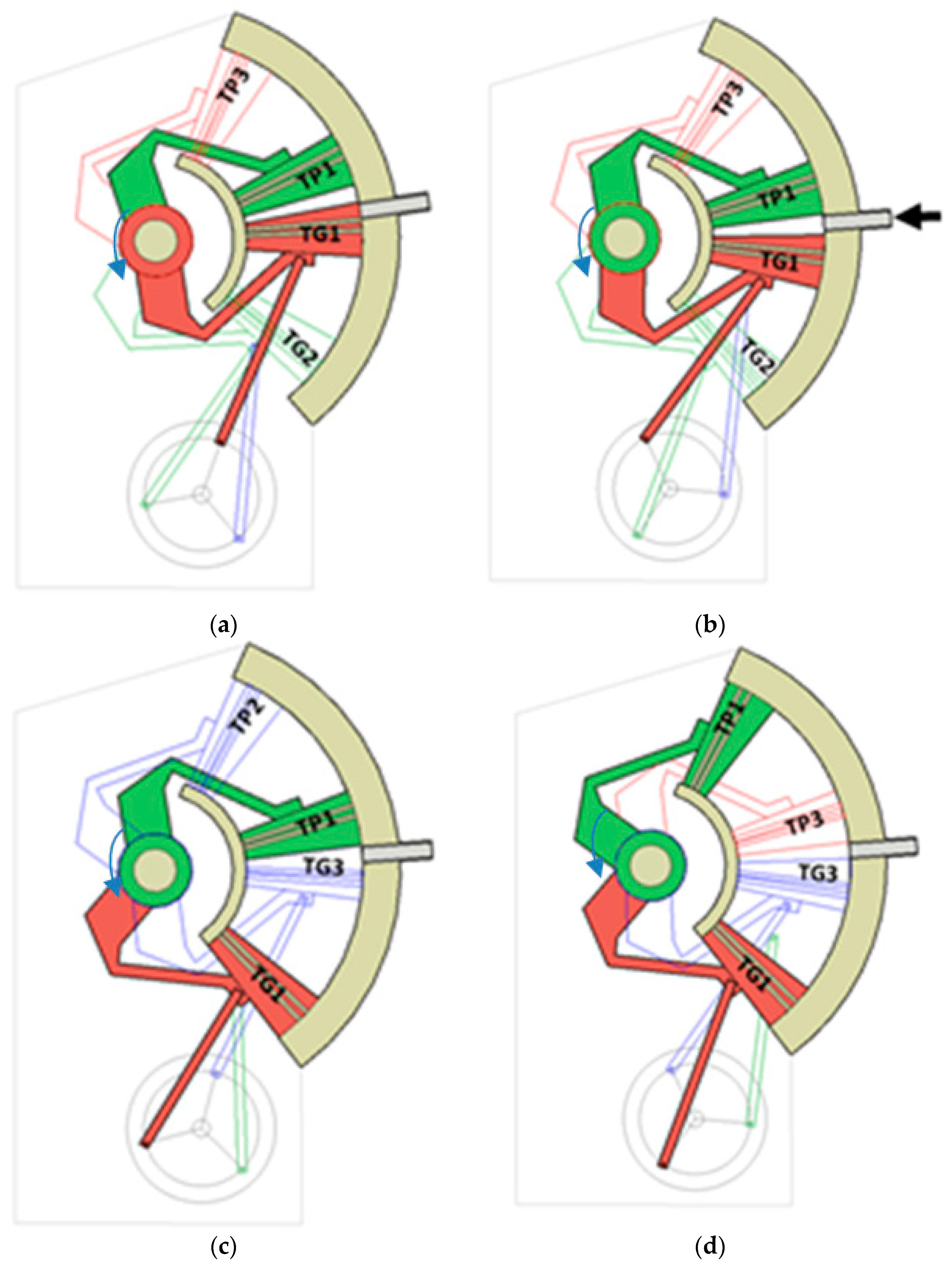
The principle of the operation of the three-cylinder engine is that two pistons in one cylinder work in opposition, in a reciprocating movement—the main TG piston and the auxiliary TP piston. These pistons, moving closer and further apart from one another create chambers of different capacity. Engine work cycle is presented in
Figure 5. The description of the work cycle begins when the TG1 piston is in the upper return point (
Figure 5a). The inlet valve is opened in the first cylinder, at the noxious space close to zero, the power stroke begins. In this position, TP1 is already moving and the capacity of the working chamber rapidly increases. The force from TP1 is transferred onto TG2 and further through the connecting rod onto the crankshaft, which is located in a favourable position for generating the torque, that is approximately 45° from Before Top Dead Centre (BTDC). High torque is generated from the beginning of the power stroke, that is 0.7 of the value of the piston force from TP1. Under pressure, the TP1 piston moves up toward the external return point pulling the crankshaft upwards; at this point the torque is generated only from the piston force of TP1. TG1 changes the position to a very slight extent. When TP1 moves by an angle of crankshaft rotation of approx. 20° (
Figure 5b), downward movement of TG1 toward the external return point begins, and the torque is now generated from TP1 and TG1, which is connected directly to the crankshaft by means of the connecting rod, and pushes it downwards. The closing of the inlet valve takes place at this stage of piston movement, performing the expansion in closed capacity (technical work). Both pistons are headed toward the external return points generating the highest torque from combined TP1 + TG1 piston forces (
Figure 5c). TP1 reaches the external return point (
Figure 5d) and TG1 continues movement generating the torque. TP1 begins movement toward the internal return point, TG1 is still moving toward the external return point, but the working space does not increase as TP1 moves in the same direction-a shift of the working chamber takes place and the outlet valve opens. TP1 and TG1 are headed toward their internal return points, decreasing the capacity of the working chamber. TP1 reaches the internal return point, stops and “waits” for TG1 (it results from the connection with the TG2 connecting rod), which approaches it at the minimum distance possible, and then both pistons move in the same direction—the working chamber shifts until TG1 reaches the internal return point the cycle repeats. Because the distribution of the crankpins on the shaft is even and equal to 120 degrees, the cycles repeat every 120 degrees in each cylinder successively, and a single cycle lasts for approximately 160 degrees of crankshaft rotation, which means that the cycles overlap, providing a more even distribution of the torque in the crankshaft rotation function.
An engine with three or a multiple of three cylinders is most beneficial for the presented solution. Very effective use of the compressed air energy for generating the torque on the engine shaft constitutes an advantage of the solution. It stems from the fact that when the greatest force acts on the pistons, the angle of the connecting rod in relation to the crankshaft is in its most favourable position. It can be noticed easily that one cylinder generates an effective torque through shaft rotation angle from 0 to 120°, unlike in the case of the classic design, in which the moment is generated only for an angle between 45 and 135°.
This engine is characterized by the efficient use of energy stored in the compressed air. The simultaneous use of two pistons means that in the first phase of the stroke, the main piston performs the main part of the work and it transmits the main driving torque. In this phase, the energy of the compressed air is optimally used, causing the air to expand. Both pistons are headed toward the external return points generating the highest torque from combined TP1 + TG1 piston forces. After reaching this position, the main torque is transmitted by the piston TG2, while the auxiliary piston TP1, starting its stroke, supports the piston TG2, using the remaining energy stored in the compressed air, leading to almost complete expansion. In this way, the energy stored in the compressed air was used more efficiently.
4. Test Stand
A test stand was built in order to determine the basic performance parameters of the compressed air engine, as shown in
Figure 6 and
Figure 7. It was assumed that the maximum operating pressure would not exceed 6 bars. The test stand will be powered by a pneumatic circuit. The value of the pressure supplied to the engine will be constant and regulated by a pressure reducer 3, the power supply system is additionally equipped with a particulate filter 2. In order to avoid the impact of the power supply pressure pulsation on the measurement results, an equalisation tank 5 was built. The air from the tank will power the prototype compressed air engine 7 through lubricator 13. The air stream is measured with flow meter 4. The air outlet is directed to the equalisation tank with a throttle valve 9, which enables controlling the air stream flowing through the engine. There is a measuring channel connected to the Thermokon DPL6/V (6) pressure difference sensor behind the equalisation tank. The load on the engine shaft is regulated with the use of brake 12 installed on the common shaft with the tested engine. The torque is measured with the Megatron DFM2X torque meter 10. The torque is measured with the Wobit MOK40-200/1224/BZ/K encoder 11. The input power is calculated on the basis of the measurement of the stream of the flowing air and operating pressure.
where: Δp-pressure drop on engine, Pa; Q-air stream, m
3/s.
Due to the fact that flow meters are calibrated in standard litres per hour, it is required to scale the results of the flow meter indications, considering operating pressure to be higher than normal. The indication of the flow meter is corrected on the basis of the following formula:
where: Q
m-measured stream, m/h; ρ
n–gas density under normal conditions (p = 1 bar and T = 20°C), kg/m
3; ρ–gas density, kg/m
3; p
n–normal pressure (p
n = 1 bar); p-operating pressure, bar.
Thus, after considering Equations (1) and (2), we obtain the formula for the input power, at controlled operating pressure value:
where: Q
m-measured stream, m/h; ρ
n–gas density under normal conditions (p = 1 bar and T = 20°C), kg/m
3; ρ–gas density, kg/m
3; p
n–normal pressure (p
n = 1 bar); p-operating pressure, bar; Δp-pressure drop on engine.
The power on the shaft of the compressed air engine is determined on the basis of the measurement of the torque and load torque. The load torque is regulated with a brake, and the speed is regulated with valve 9, throttling the stream of the flowing air. The power of the compressed air engine is calculated from correlation:
where: M-torque, Nm; n-speed, rpm.
The efficiency is calculated on the basis of the calculated power supply and power on the engine shaft, in accordance with correlation:
The input power consists of the power on the engine shaft and power dissipation. The main reason for power dissipation is resistance to motion, losses associated with leaks, power lost to engine lubrication systems as well as losses associated with gas changes.
5. Results
A number of tests were carried out under various conditions of engine operation in order to determine the operating parameters of the compressed air engine. In order to determine the maximum speed of the engine, it was started without load with the outlet valve 9 completely open. Torque on shaft in this system is zero, so all the energy of the supplied air is used to overcome engine’s own resistance, and the stream of the supplied air will be directly converted into engine speed.
Figure 8 presents the dependence of the maximum achievable speed of the engine on the stream of the flowing air. A linear dependence with a slope of about 0.75 rotation per stream was obtained for the model engine.
Engine Friction Losses increase as the speed increases.
Figure 9 presents the characteristics of changes in speed depending on the decrease in pressure on the engine. The correlation is linear with an inclination of 0.8 rotation per moment value. The inclination of the characteristics indicates dynamic losses associated with engine operation.
If the engine is loaded with torque, some part of the supplied energy will be converted into mechanical power. The tests consisted of supplying the engine with a continuous stream of air of different working pressures and then changing its load.
Figure 10 presents the correlation of change in speed on the load moment of the engine. This way, a very typical characteristic of compressed air engines was obtained, where the speed strongly depends on the engine load. In order to achieve constant speed on the shaft, it is necessary to regulate the stream of the supplied air. As the operating pressure increases, the impact of the load on the speed of the engine decreases. It indicates that it is more beneficial for this type of engine to operate at higher working pressures. It stems from the fact that the required energy for the transfer of the oil lubricating engine elements has a large impact on engine efficiency. It indicates the direction of the search for the solutions concerning the improvement of engine efficiency. Undoubtedly, the centrifugal lubrication system will consume much less energy.
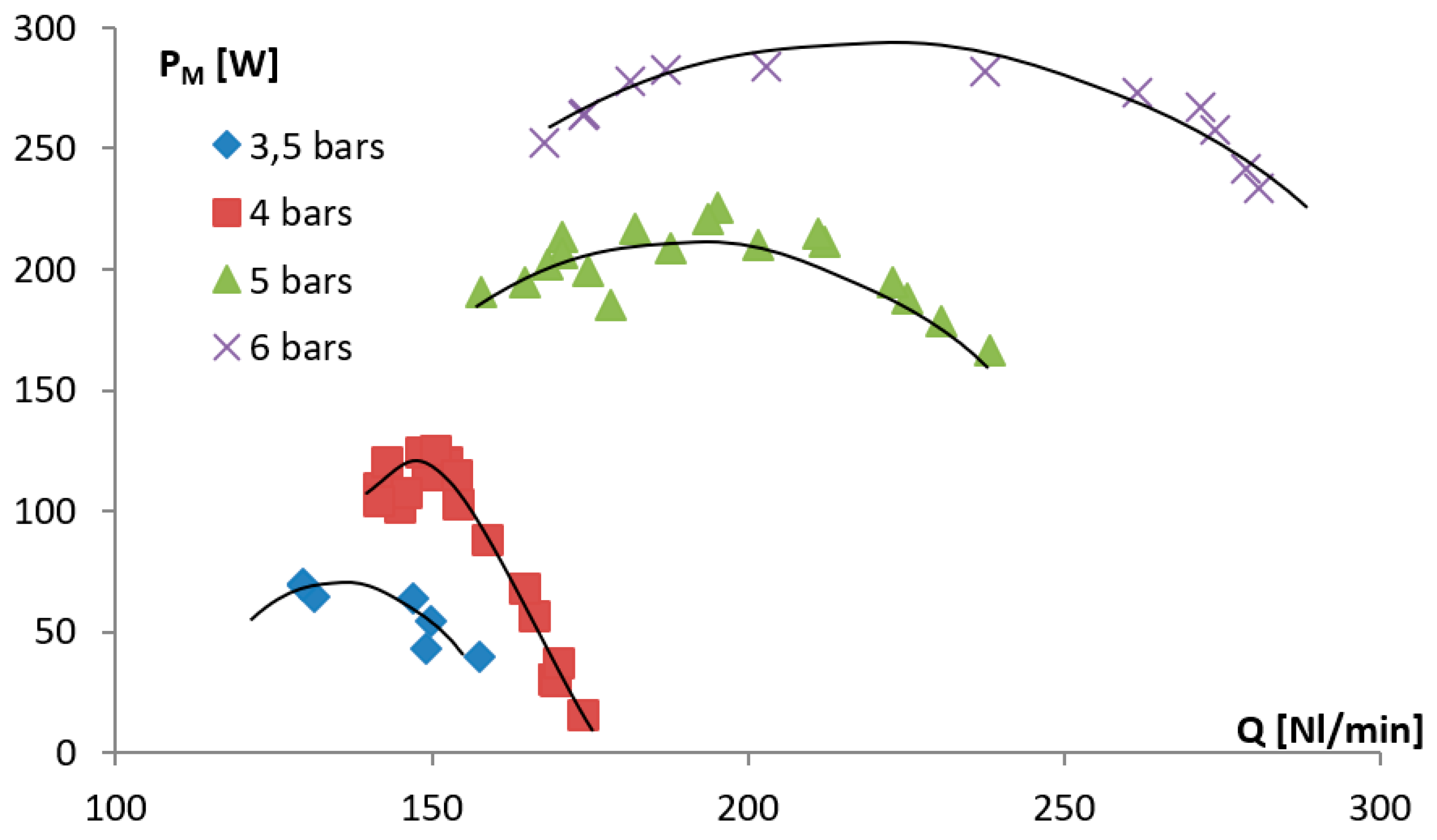
The power on the engine shaft depends both on the operating pressure and the load.
Figure 10 presents the dependence of the power obtained on the engine shaft on the speed. Engine speed results from the change in engine load. As can be seen in the presented characteristics, the power on the shaft reaches a certain maximum for a given speed. As the operating pressure increases, the maximum is reached at a higher speed. The shifting of the maximum power to the right along with the pressure increase in the diagrams is caused by the better sealing of the engine. Engines of this type are characterized by the fact that in the end positions, the valves open and close. With less pressure, the engine obtains less torque on the shaft. Hence, the greater percentage of power is used to overcome the engine’s own resistance, which results in a lower maximum speed. In convergence, the non-sealing time of the valves related to the rotation of the valve cam is longer. This results in a greater percentage of air loss. As a consequence, lower rotational speed and efficiency are obtained and this is the cause of the maximum power shift. Therefore, one of the parameters affecting the efficient use of the engine is the appropriate selection of the size and power of the engine for a specific operating pressure. The value of the pressure of the supplied air also has a significant impact on the obtained power on the shaft.
A significant operating parameter of compressed air engines is the amount of the used air in relation to the power generated on the shaft.
Figure 11 presents the dependence of the power obtained on the engine shaft on the stream of the air supplied to it at various values of operating pressure. The engine was powered by air with constant pressure, and then regulated by engine load. A change in the load of the engine causes a change in the speed, which results in a change of the stream of the gas flowing through the engine. Higher operating pressure causes the engine to maintain the maximum power generated on the shaft within a greater range of speed. After exceeding the critical value of the load stream, the power decreases very rapidly. It is caused by a decrease in the speed. As the operating pressure increases, the greater part of the air stream escapes through the leaks without performing any work.
The obtained results were compared with selected series-produced engines.
Table 1 presents a comparison of the results of two piston engines, MP165 and MP3000 produced by STAWMET, with the tested engine. Comparing the results for two commercial engines, the proposed solution shows much lower air consumption in relation to the obtained power. The much more powerful engine MP 3000 shows significantly less air consumption per watt of power. This is typical of high-power engines where the achieved efficiencies are usually higher. Compared to an engine with a power slightly higher than the proposed MP 165, much better results were obtained, which proves the purposefulness of building engines of this design. Comparing the parameters of the engines from
Table 1, the engine manufactured in accordance with the PL216801 patent shows lower air consumption in relation to the power generated on the shaft.
In order to determine the efficiency of the engine, depending on the speed and operating pressure, tests consisting of supplying the engine with a stream of air with constant pressure were carried out.
Figure 12 presents the results for changing engine load. The highest engine efficiencies coincide with engine speeds at which the highest powers on the shaft for a given operating pressure were obtained. Increasing the operating pressure makes sense only up to a certain value. Further increases cause the efficiency to stall or even decrease. The optimum operating pressure in the model engine is the pressure between 4 and 5 bars.


