Article

Electromagnetic Field Tests of a 1-MW Wireless Power Transfer System for Light Rail Transit

1
Smart Electrical & Signaling Division, Korea Railroad Research Institute (KRRI), Uiwang 16105, Korea
2
Advanced Railroad Technology Planning Department, Korea Railroad Research Institute (KRRI), Uiwang 16105, Korea
3
School of Electrical, Electronics and Communication Engineering, Korea University of Technology and Education (KOREATECH), Cheonan 31253, Korea
*
Author to whom correspondence should be addressed.
Energies 2021, 14(4), 1171; https://doi.org/10.3390/en14041171
Submission received: 10 February 2021 / Revised: 17 February 2021 / Accepted: 18 February 2021 / Published: 22 February 2021
(This article belongs to the Special Issue Electromagnetic Modeling in Power Electronics)

Abstract

:
The high-power wireless power transfer (WPT) system in railways does not require physical contact to transfer electrical power, is electrically safe, and reduces maintenance costs from wear and tear. However, a high-power system generates a strong magnetic field that can result in problems of electromagnetic field (EMF) exposure and electromagnetic interference (EMI). In this study, EMF and EMI were measured at various positions under in-motion environment conditions for a 1-MW WPT light rail transit system. The measured maximum EMF was 2.41 μT, which is lower than the international guideline of 6.25 μT for the various locations with a potential presence of passengers. The measured EMI also satisfied international standards in the frequency range of 150 kHz–1 GHz.

1. Introduction

The wireless power transfer (WPT) system transfers electrical power using magnetic fields without any contact with electrical cables, avoiding the electrical [1] and mechanical [2] issues in conventional contact systems. The WPT technology has already been utilized in small electronic devices and home appliances such as mobile phones, and with the rapid development in battery technology, the WPT system can be applied to high-power systems such as electric vehicles (EVs) and railways. WiTricity entered the WPT system market for EVs in 2018 [3]. WPT systems for stationary applications have a power of 11 kW and an efficiency of 90–93%. Moreover, the dynamic WPT system has been tested at a frequency of 85 kHz, and it could attain a power of 20 kW. However, a WPT system with a higher power has been applied on an electric bus. In 2013, Korea Advanced Institute of Science and Technology applied a 100-kW WPT system on an electric bus, which was plied on an actual route [4]. The frequency was 20 kHz, and the air gap was approximately 300 mm. In 2019, Toshiba applied a 44-kW wireless charging technology on an electric bus [5]. An efficiency of approximately 85% was achieved with a frequency of 85 kHz. The transmission distance between the charging pads was 100–130 mm.
In addition, high-power WPT systems of more than 100 kW have been studied for applications on railways. In 2013, Bombardier Inc. demonstrated the application of a 200-kW WPT technology for light rail transit [6,7,8]. The notable feature of this technology was the use of a three-phase current. In 2015, the Korea Railroad Research Institute applied a 1-MW WPT system where the frequency was 60 kHz and the air gap was 50 mm on a high-speed railway system and demonstrated its successful pilot operation [9]. The same year, the Railway Technical Research Institute (RTRI) applied a 50-kW WPT system with a frequency of 10 kHz, an air gap of 75 mm, and the primary current at 400 A for application in railways [10].
Although there is an insufficient number of studies or reports regarding WPT systems with a power of more than 500 kW, a number of major research institutes have plans to perform tests by increasing the power transfer capacity. In addition, active R&D is underway for dynamic charging or distributed charging at stations rather than a simple system of stationary charging. In particular, dynamic charging is preferred for high-power WPT systems because the charging duration becomes longer with stationary charging.
One of the challenges for commercial applications of high-power WPT technology arises from the electromagnetic field (EMF) and electromagnetic interference (EMI) [11,12,13,14]. The levels of EMF and EMI exposure to humans during the operation of the WPT system must comply with the international standards. At the WPT frequency of 60 kHz, the standard limit of EMF is 6.25 μT. The EMI standard is defined from 150 kHz up to 1 GHz, and the limit is different for each frequency. Although the EMF and EMI of WPT systems have been discussed in certain previous studies, test results for various conditions still need to be presented. The technology for EMF reduction in the operation of the WPT system has been mostly investigated on a laboratory scale or using simulations, where the major techniques modified the transmitter/receiver coil design and the shape of the shielding material.
A technique using two loops in the transmission line has been proposed for reducing EMI in WPT-powered buses [15,16]. Oak Ridge National Laboratory (ORNL) proposed a method based on magnetic shielding for reducing EMF in a 100-kW wireless EV charging system [17]. In addition, the National Renewable Energy Laboratory (NREL) measured the EMF and touch current at various locations for a 25-kW inductive power transfer system applied to a minibus and presented the measurement data [18]. Moreover, a method has been proposed for reducing EMF by using a three-phase current in the transmitter coil of a WPT system [19]. Furthermore, a technique has been developed to reduce EMF by attaching additional coils to the outside of the transmitter/receiver coils, and fixedly attached or switch-controlled passive and active coils have been proposed as well [20,21,22]. All previously presented EMF measurements and leakage reduction techniques have been performed at the laboratory level or tested at medium power less than 100 kW. The EMF and EMI measurement data in the actual high-power WPT system have not been presented.
In this study, we present the EMF and EMI levels measured based on stationary and dynamic charging application of a WPT system for light rail transit. Recently, we applied a 1-MW WPT system on the light rail transit of Korea-automated guideway transit (K-AGT) and measured the EMF and EMI levels in various environments during a test operation. The EMF and EMI standards applicable to WPT systems are briefly outlined in Section 2. Thereafter, Section 3 briefly introduces the newly developed WPT system for light rail transit. The EMF and EMI values measured during operation on the test route are presented in Section 4, and the obtained results are concluded in Section 5.

2. International Guidelines on EMF and EMI

2.1. EMF Guidelines

In this study, the high-power WPT system for light rail transit used a frequency of 60 kHz. Therefore, the applicable regulations for this frequency and that for EMF are reviewed in this section. The International Commission on Non-Ionizing Radiation Protection (ICNIRP) 1998 [23] presented reference levels for general public exposure to frequency bands of 1 Hz–300 GHz, whereas ICNIRP 2010 [24] provides reference levels for frequency bands from 1 Hz to 10 MHz. In particular, ICNIRP 1998 represents a more rigorous standard than ICNIRP 2010 for the frequency band of 60 kHz. Thus, the current study analyzed the measurements by applying the ICNIRP 1998 standard, which is an adopted standard for human protection against electromagnetic fields in South Korea. Table 1 depicts the standards of electromagnetic fields for the general public, as presented in the ICNIRP guidelines.
The EMF measurement methods for the railway sector along with the measurement locations of the rolling stock are specified in IEC62597 [25], according to which the measurement location is divided for the rolling stock and the surrounding infrastructure. The measurements inside the rolling stock are specified to be taken at three points: 0.3 m, 0.9 m, and 1.5 m from the floor. In addition, a distance of at least 0.3 m needs to be maintained from the wall. For measurements outside the rolling stock, the points must be horizontally separated from the vehicle by at least 0.3 m, and the measurements are to be acquired at 0.5, 1.5, and 2.5 m in terms of height. In addition, the measurement points on the platform need to be separated at least 0.3 m from the end of the platform at specified heights of 0.9 m and 1.5 m. Moreover, the power supply system installed in the infrastructure ought to have a minimum separation distance of 0.3 m, and its EMF has to be measured at 0.3, 0.9, and 1.5 m in height.

2.2. EMI Guidelines

Radiated emission (RE) for light rail systems is specified in IEC 62236-2: 2018 [26] and IEC 62236-3-1: 2018 [27]. According to IEC standards, the reference value of RE varies with the type of rolling stock, and the strictest rules have been applied for light rail systems plying in urban areas. In addition, the H-field is specified to be measured in the frequency band 150 kHz–30 MHz, whereas the E-field is measured in the 30 MHz–1 GHz frequency band. The limits of the fields for the light rail system defined in IEC standards can be formulated with the following equations:
H m a x ( f ) = 60 21.7 l o g 10 ( f 150 , 000 ) dB μ A / m   for   150   kHz 30   MHz   ( 60   dB μ A / m   at   150   kHz ) ,  
E m a x ( f ) = 85 16.4 l o g 10 ( f 30 , 000 , 000 ) dB μ V / m   for   30   MHz 1   GHz   ( 85   dB μ V / m   at   30   MHz ) ,
where f is the frequency in Hz, Hmax(f) is maximum magnetic field intensity, and Emax(f) is maximum electric field intensity. However, the fields at 60 kHz are not defined. Thus, it is necessary to examine whether or not the RE of the harmonic frequencies of the operating frequency of WPT system exceeds the standard level. The magnetic field was measured at 10 m away from the center of the track with a loop antenna placed at a height of 1–2 m. The electric field was measured at a distance of 10 m from the center of the track using a log-periodic antenna at a height of approximately 2.5–3.5 m.

3. WPT System for Light Rail Transit

3.1. Overview of WPT System for Light Rail Transit

The WPT system manufactured for the K-AGT light rail transit is presented in Figure 1; it was designed with 1 MW, and the detailed specifications are listed in Table 2. It used four pick-ups and generated 250 kW of rated power output per pick-up. The output voltage was derived at 750 V DC to match the supply power of the existing light rail transit. The air-gap distance between the transmission line and the pick-up was designed to be 60 mm. In addition, the batteries of the stated system could be charged when both stationary and in motion. Both driving energy and battery-charged energy was supplied to the WPT rolling stock in sections with a transmission line, but the sections without a power line could utilize only the battery energy for running, and a power supply system using a third rail was not required. As the rolling stock used the maximum power in the accelerating section post departure, the WPT transmission line was installed in this section to ensure sufficient power supply for charging and driving.

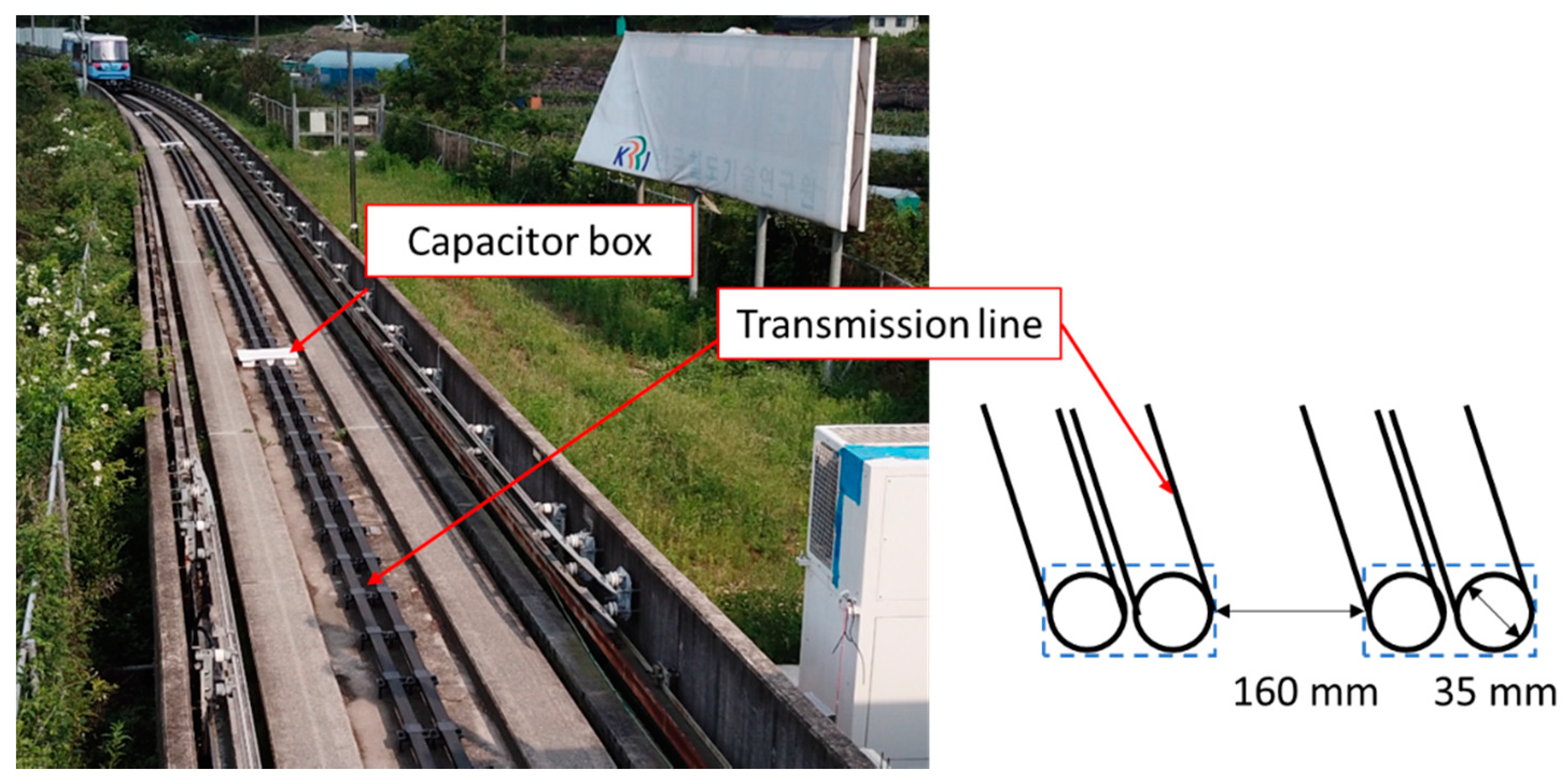
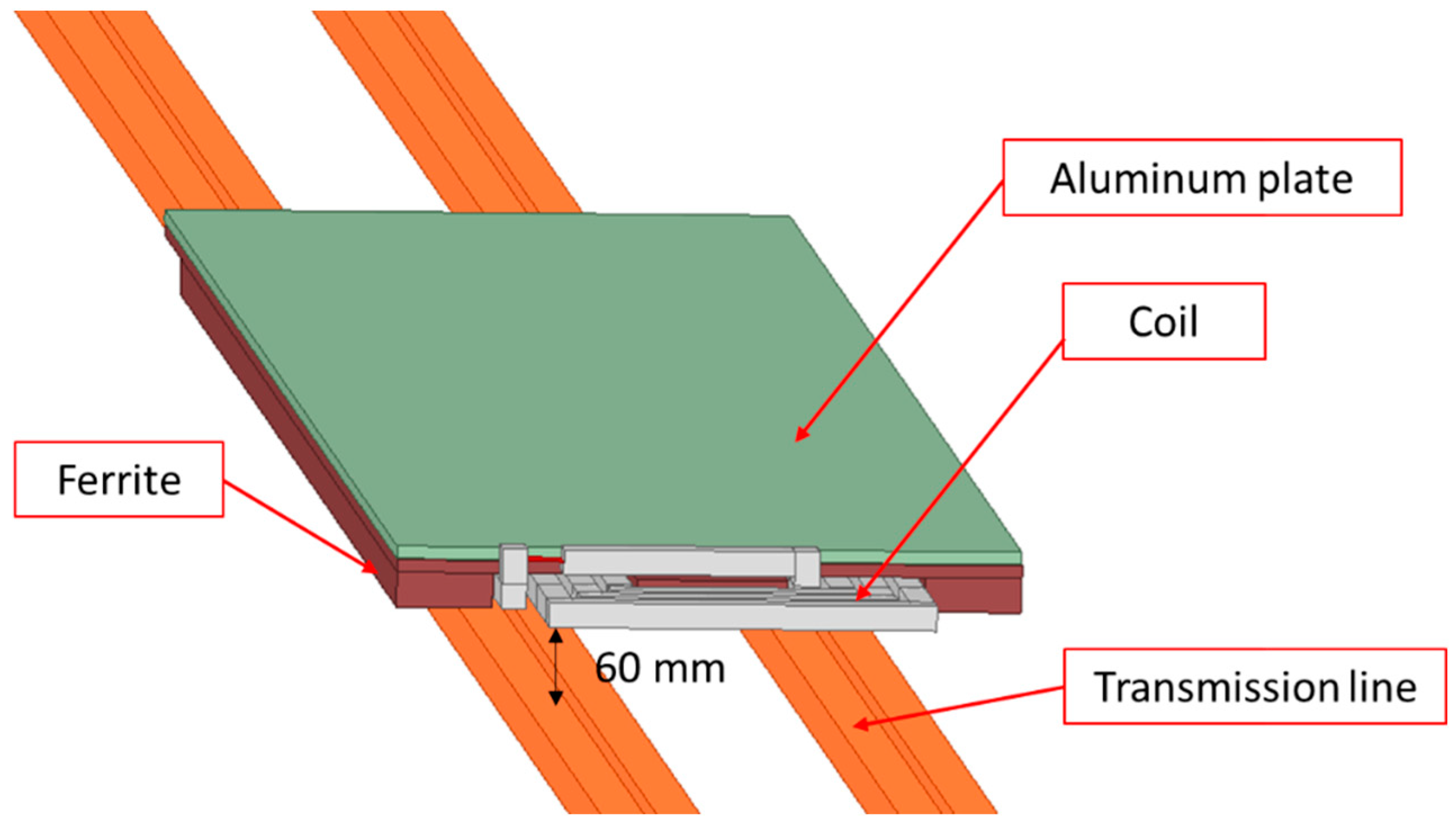
3.2. Structure of the Power Line and Pick-Up

As depicted in Figure 2, the transmission line was set with wires carrying a maximum current of 500 A wrapped around the track, where two cables of 35 mm diameter were connected in parallel to achieve this purpose. The high-frequency loss in the cable was minimized with a Litz wire comprising 25,200 strands, and the inside of one cable was approximately 160 mm from that of the opposite cable. The width of the cable was set to be narrow so that the magnetic field formed in the center part of the rolling stock can be reduced at points away from the power line without using core shielding. In addition, the ferrite core was removed to reduce the cost of the transmission line as compared with the existing method of using the core therein. Moreover, the length of the transmission line was set at 200 m in consideration of the distance traveled by the K-AGT rolling stock till accelerating up to the maximum speed.
The structure of the pick-up is illustrated in Figure 3, where the pick-up contains a receiving coil that receives the magnetic field, a rectifier that converts AC into DC, and a regulator. The coil was formed by winding a 20-mm-diameter cable four times, and the regulator was designed for a constant output at 750 V by rectifying the voltage of the pick-up. In particular, the rated power per pick-up was 250 kW, and the maximum current flow in the pick-up was set to 392 A. In addition, a ferrite core and an aluminum plate were used above the cable. The ferrite core served to increase the pick-up efficiency and reduce the magnetic field leakage from the pick-up, whereas the aluminum plate served to prevent the magnetic field generated from the lower side of the rolling stock to transmit into the vehicle.

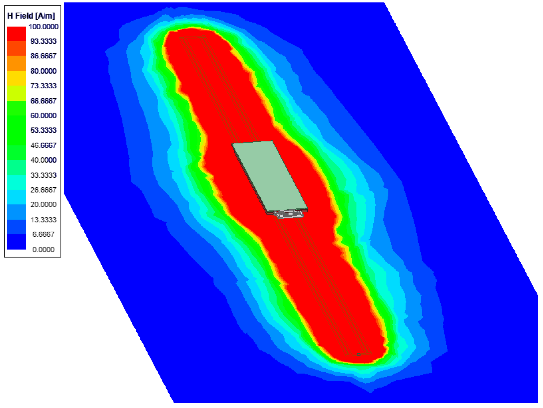
3.3. Analysis of Electric Field by Simulation

The magnetic field generated by the WPT system was analyzed under simulation performed using the designed and manufactured transmission and pick-up structures, as depicted in Figure 4. A 3D electromagnetic analysis tool, Ansys HFSS, was used for the full-wave simulation. The cables used for the transmission line and pick-up were assumed as copper with a conductivity of 5.8 × 10⁷ S/m. The top of the transmission line and the bottom of the pick-up was separated by 60 mm to maintain the primary and pick-up coils as close as possible, and allow a small margin of around 50 mm as the minimum distance between the track surface and the underside of the vehicle. In addition, the current flowing through the transmission line during the actual operation of the light rail transit was set to 450 A. Moreover, the magnetic field value around the pick-up did not alter significantly with the number of pick-ups increasing longitudinally over the transmission line; thus, only a single pick-up was used in the simulation. Furthermore, a 180-nF capacitor was connected in series with the coil to ensure resonance of the pick-up at 60 kHz.
The magnetic field distribution between the transmission line and the pick-up is presented in Figure 5. An impedance-matching method was applied to ensure maximum output of the pick-up with 2 Ω at its output terminal. As can be observed from Figure 5, a stronger magnetic field was formed sideways around the pick-up owing to a phase difference of 90° between the magnetic field generated by the transmission line and that produced from the current flowing in the pick-up coil—transferring power to the pick-up. Therefore, the net magnetic field was augmented by the magnetic fields generated by both the transmission line and the pick-up.
The pick-up of the actual light rail system was attached to the underside of the rolling stock, and an external infrastructure such as a platform was present for the train to stop. Therefore, a simulation considering the presence of a platform was performed to consider all these effects. The magnetic field distribution in Figure 6 illustrates the cross-section of the location where the pick-up was attached. Here, the maximum range of the magnetic field was derived at 5 A/m in accordance with the maximum human-exposure level. In addition, the rolling stock was assumed as a perfect conductor, and the platform was assumed of concrete with a dielectric constant of 6 and a loss tangent of 0.06. Although the actual pick-up was attached to the underside of the rolling stock, Figure 6a depicts the distribution of a magnetic field for a transmission line and pick-up without the rolling stock. On the contrary, Figure 6b presents the magnetic field distribution for the pick-up attached to the underside of the rolling stock, which serves to shield the magnetic field. Moreover, the amount and intensity of the magnetic field on the platform were observed to have evidently reduced. Therefore, the EMF levels of the designed system will not exceed the reference level in an actual environment with the rolling stock.

4. Measurement Results of EMF and EMI

The EMF and EMI were measured on the application of the WPT on the K-AGT rolling stock to determine whether the manufactured WPT system satisfied the standards for electromagnetic waves. In addition, the rolling stock consumed lesser power than the design owing to the battery charging capacity and the vehicle power consumption limit at low speed. As the charging speed varied based on the actual battery level, the measured values could change as well. The following measurement results were obtained using two pick-ups (rated power: 500 kW) in the in-motion state, and 150 kW of power was transferred during charging in the stationary state. Moreover, up to 400 kW of power was transferred during dynamic charging. The measurement values stated in the results correspond to the above conditions.
The various EMF and EMI measurement points are illustrated in Figure 7. The measurements were performed when the rolling stock was stationary on the platform and when it started moving with the use of adequate energy. The EMF was measured at two locations inside the rolling stock, one on the platform, one outside the rolling stock, and one around an inverter that generated high-frequency power. In addition, the only RE for EMI was measured in this paper. The RE measurement of rolling stock was performed for three cases: stationary state, low-speed state, and high-speed state. For the stationary and low-speed states, the measurements were obtained at point A, whereas the measurements for the high-speed state were acquired at point B, as the maximum speed can be achieved only after operating a sufficient distance.

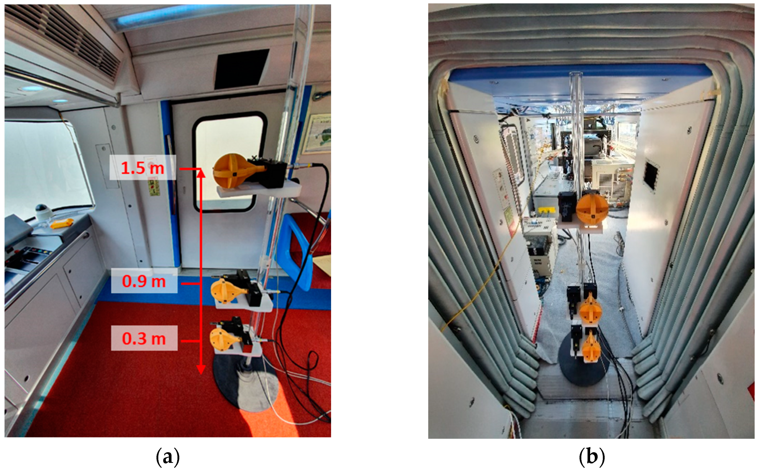
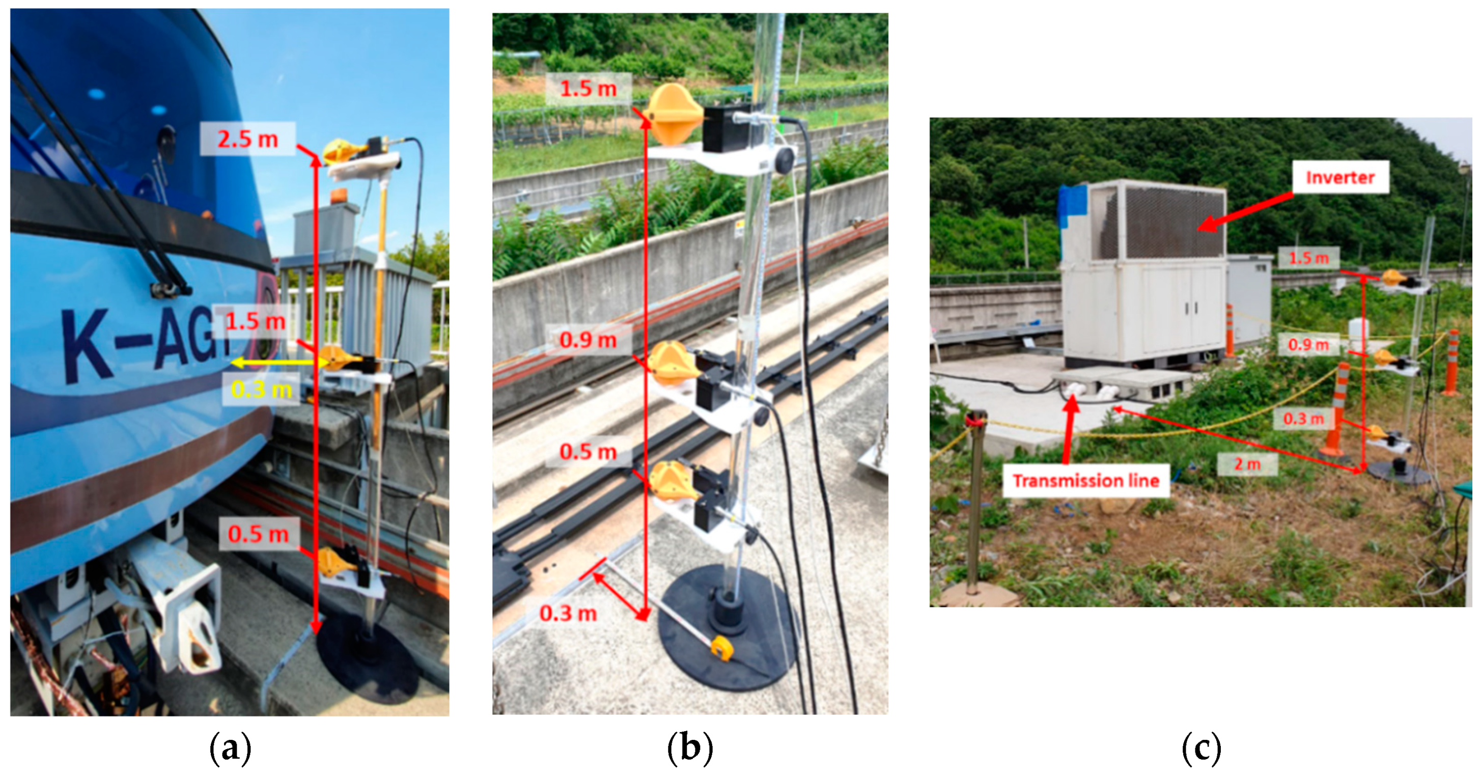
4.1. EMF Measurement Results

When the rolling stock is in dynamic charging the battery with the maximum power collection state, Figure 8 depicts the EMF measurement points inside the rolling stock, and Table 3 outlines the measurement results. Three magnetic field testers (FT3470-50, Hioki) were used to measure magnetic fields at each point simultaneously. The width of the rolling stock was 2.4 m, and the measurement inside the rolling stock was acquired at the midpoint—the closest position to the external transmission line, i.e., 1.2 m away from the end of the rolling stock. The measurement location from the exit side and that at the gangway point connecting the vehicles are portrayed in Figure 8a,b, respectively. The magnetic field strength measured on the gangway side was four times larger than that on the exit side owing to the gaps on the gangway floor. In addition, the sidewalls were covered with a non-metallic material such as rubber that provided insufficient shielding from the magnetic fields. Nonetheless, all the measured magnetic field strengths satisfied the reference levels as per the ICNIRP 1998 standard, because the inside of the rolling stock is 1.2 m away from the transmission line, and the bottom of the gangway is made of metal.
The three EMF measurement points—outside the rolling stock, on the platform, and on the inverter—are presented in Figure 9. First, the measurements outside the rolling stock were obtained on the track separated by 0.3 m from the front of the light-rail rolling stock. As the transmission line, in this case, was installed at the center of the track, the measurement could not be acquired at this point. Therefore, a point 1 m away from the center of the line was considered for the measurement. The second measurement point was located on the platform, where the passengers usually wait for the light rail transit, and the exit where the passengers stand in most cases. Therefore, the EMF measurement location was selected at a point 0.3 m away from the end of the platform, which is the closest point to the transmission line for the exit location. Although the high-frequency power of 60 kHz was generated by the inverter, the amount of EMF leakage was small because the inverter was shielded with a metal housing. However, a strong magnetic field could be generated near the cable connection, as the transmitter cable was buried in the floor. Therefore, a fence was installed at a distance of 2 m to restrict public access in the vicinity of the inverter, and the magnetic field was measured at a point 0.3 m away from the fence.
The measurement results for the instant (departure while charging) when the largest amount of power was transferred to the light rail transit are listed in Table 4. All the measurements in the platform were within the standard value, because the measurement points were located at a sufficient height—almost 1 m higher than the transmission line. In addition, the magnetic field value at a point 0.5 m away from the ground and in front of the rolling stock was measured at 14.5 μT, which exceeds the standard value. However, this does not cause a practical problem because the transmission line is operated with the flow of current only when the train enters, and the measurement point was located in an area where human access to the track side is strictly restricted and the rolling stock is in motion. Thus, the measurement is not posing any risk of human exposure. In addition, the reference level in the revised ICNIRP 2010 is increased to 27 μT; therefore, the measured value satisfies this standard value. Although the magnetic field strength in the vicinity of the inverter with the buried transmission cable is higher than that on the platform, the measurement was within the reference value range. Moreover, the inverter is a high-voltage electric device, and a safety fence can be installed around the inverter to restrict public access. In this case, the risk of exposure to the magnetic field would be significantly reduced.
Simulation results were also presented for the platform environment and outside of the vehicle in Table 4. It can be seen that the trend of the simulation and measurement result are similar. The numerical differences are due to the simplification of the vehicle and platform structures in the simulation. Only EMF data were presented inside the vehicle and near the inverter due to the difficulty of simulation.

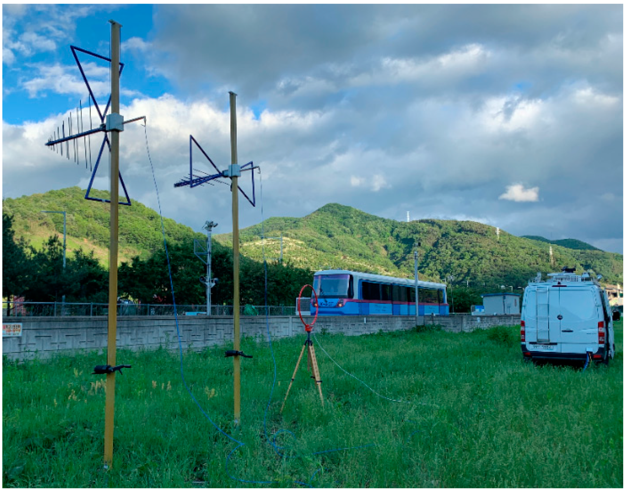
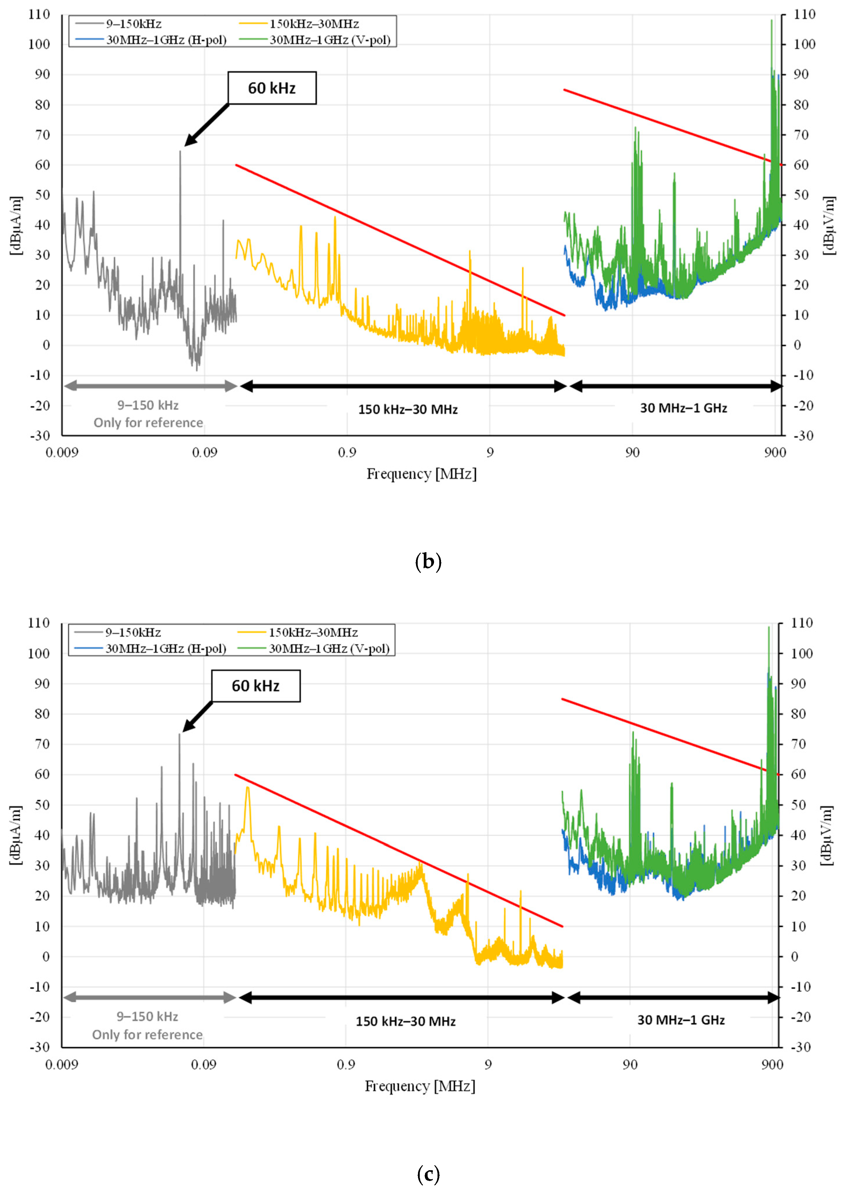
4.2. EMI Measurement Results

The measurement location of the RE is shown in Figure 10, where a loop antenna and a log-periodic antenna of vertical and horizontal polarization was used at a point 10 m vertically away from the center of the transmission line. The measurements were obtained according to the train operation mode under the condition of WPT, and the measurements were acquired for three categories: stationary, low-speed motion (0–35 km/h), and high-speed motion (60 km/h). The measurements for the stationary and low-speed states were obtained around the power inverter (point A in Figure 7) and those for the high-speed state were measured at the end of the transmission line (point B in Figure 7). The EMI measurement data are presented in Figure 11. Although the frequency band of 0–150 kHz was not defined in the standard, these values represented the magnetic field measurements for reference purposes. As the RE of the WPT system required to be measured, the EMI was initially measured when the light rail system was not under operation, as illustrated in Figure 11a. Moreover, certain values exceeding the standards corresponded to the broadcasting and communication bands. Figure 11b presents the EMI measurements during wireless charging in the stationary state. At frequencies beyond 150 kHz, all the measurements were under the standard levels, and at the wireless charging frequency of 60 kHz, the magnetic field was measured at 64 dBμA/m. The EMI measurements in low- and high-speed states of the rolling stock during dynamic charging are presented in Figure 11c,d, where the measurement data can be observed to be similar. During the same wireless charging, the noise level in low-speed operations was slightly higher than that of high-speed operations, because the rolling stock used energy with maximum acceleration at low speed, whereas less energy was used for the coastdown at high speeds. In addition, the noise level was observed to rise corresponding to various frequencies and results in a stationary state. In particular, noise from the rolling stock operations was generated at a frequency of around 180 kHz, which increased the wireless power energy. Furthermore, the noise was presumably generated from the vehicle itself, such as during switching of propulsion inverters of the rolling stock.

5. Conclusions

The current study presented the results of EMF and EMI measurements acquired inside and around the rolling stock in a light rail transit system operating in a real environment using a WPT system. This study is the first to present EMF and EMI data in accordance with the railway standard for the 1 MW WPT system. The EMF simulations shows that the EMF varied according to the platform environment of the rolling stock. In addition, the measured EMF and EMI were below the reference level, thus satisfying the safety standards. Moreover, the EMF inside the rolling stock was weak, because the magnetic field was shielded by the vehicle itself. However, the magnetic field values in the gangway were relatively higher than those inside the rolling stock owing to the presence of several gaps in the vehicle body at this location. Therefore, magnetic field reduction method at the gangway needs to be considered for using a strong magnetic field in the future. As the height of the platform in the railway environment is adequate to be well separated from the transmission line, the magnetic field strength on the platform satisfied the standard reference level. However, a strong magnetic field can be produced near the buried transmission cable in the high-frequency power inverter. Therefore, the standard level at this location can be satisfied by maintaining a safe distance with a fence around the inverter. In addition, the installation of additional shielding structures must be considered before the transmission line reaches the track. The current study verified that all the measurements of the magnetic field obtained from recommended locations for a high-power WPT system satisfied the reference levels in the ICNIRP 1998 standard, thereby indicating the commercial potential of the WPT system.

Author Contributions

Conceptualization, G.L., M.Y.K. and J.H.K.; methodology, G.L. and J.H.K.; software, G.L., C.L. and D.J.; validation, G.L. and M.Y.K.; formal analysis, G.L. and M.Y.K.; investigation, G.L. and J.H.K.; resources, G.L., M.Y.K., C.L. and D.J.; data curation, C.L. and D.J.; writing—original draft preparation, J.H.K. and G.L.; writing—review and editing, G.L. and J.H.K.; visualization, G.L. and J.H.K.; supervision, B.-S.L.; project administration, B.-S.L., M.Y.K. and G.L.; funding acquisition, B.-S.L. and M.Y.K. All authors have read and agreed to the published version of the manuscript.

Funding

This research was supported by a grant from R&D Program of the Korea Railroad Research Institute, Republic of Korea, and by the Railroad Technology Development Program funded by the Ministry of Land, Infrastructure and Transport (MOLIT) of the Korean government under Grant 19RTRP-B097048-05.

Institutional Review Board Statement

Not applicable.

Informed Consent Statement

Not applicable.

Conflicts of Interest

The authors declare no conflict of interest.

References

  1. Midya, S.; Bormann, D.; Schutte, T.; Thottappillil, R. Pantograph arcing in electrified railways—Mechanism and influence of various parameters—Part I: With DC traction power supply. IEEE Trans. Power Del. 2009, 24, 1931–1939. [Google Scholar] [CrossRef]
  2. Song, Y.; Liu, Z.; Rønnquist, A.; Nåvik, P.; Liu, Z. Contact wire irregularity stochastics and effect on high-speed railway pantograph–catenary interactions. IEEE Trans. Instrum. Meas. 2020, 69, 8196–8206. [Google Scholar] [CrossRef]
  3. Zhang, B.; Carlson, R.B.; Smart, J.G.; Dufek, E.J.; Liaw, B. Challenges of future high-power wireless power transfer for light-duty electric vehicles—technology and risk management. eTransportation 2019, 6, 100088. [Google Scholar] [CrossRef]
  4. Song, K.; Koh, K.E.; Zhu, C.; Jiang, J.; Wang, C.; Huang, X. A Review of dynamic wireless power transfer for in motion electric vehicles. Wirel. Power Transf. 2016, 109–128. [Google Scholar] [CrossRef] [Green Version]
  5. Obayashi, S.; Shijo, T.; Suzuki, M.; Moritsuka, F.; Ogawa, K.; Ogura, K.; Kanekiyo, Y.; Ishida, M.; Takanaka, T.; Tada, N.; et al. 85 kHz band 44 kW wireless rapid charging system for field test and public road operation of electric bus. World Electr. Veh. J. 2019, 10, 26. [Google Scholar] [CrossRef] [Green Version]
  6. Elliott, G.A.J.; Covic, G.A.; Kacprzak, D.; Boys, J.T. A new concept: Asymmetrical pick-ups for inductively coupled power transfer monorail systems. IEEE Trans. Magn. 2006, 42, 3389–3391. [Google Scholar] [CrossRef]
  7. Brecher, A.; David, A. Review and Evaluation of Wireless Power Transfer (WPT) for Electric Transit Applications; No. FTA Report No. 0060; John, A., Ed.; Volpe National Transportation Systems Center: Cambridge, MA, USA, 2014. [Google Scholar]
  8. Winter, J.; Mayer, S.; Kaimer, S. Inductive power supply for heavy rail vehicles. In Proceedings of the 3rd International Electric Drives Production Conference (EDPC), Nuremberg, Germany, 29–30 October 2013; pp. 1–9. [Google Scholar] [CrossRef]
  9. Kim, J.H.; Lee, B.-S.; Lee, J.-H.; Lee, S.-H.; Park, C.-B.; Jung, S.-M.; Lee, S.-G.; Yi, K.-P.; Baek, J. Development of 1-MW inductive power transfer system for a high-speed train. IEEE Trans. Ind. Electron. 2015, 62, 6242–6250. [Google Scholar] [CrossRef]
  10. Ukita, K.; Kashiwagi, T.; Sakamoto, Y.; Sasakawa, T. Evaluation of a non-contact power supply system with a figure-of-eight coil for railway vehicles. In Proceedings of the 2015 IEEE PELS Workshop on Emerging Technologies: Wireless Power (2015 WoW), Daejeon, Korea, 5–6 June 2015. [Google Scholar] [CrossRef]
  11. Campi, T.; Cruciani, S.; Santis, V.D.; Maradei, F.; Feliziani, M. EMC and EMF safety issues in wireless charging system for an electric vehicle (EV). In Proceedings of the International Conference of Electrical and Electronic Technologies for Automotive, Torino, Italy, 15–16 June 2017. [Google Scholar] [CrossRef]
  12. Jeschke, S.; Maarleveld, M.; Baerenfaenger, J.; Schmuelling, B.; Burkert, A. Challenges in EMC testing of EV and EVSE equipment for inductive charging. In Proceedings of the International Symposium on Electromagnetic Compatibility (EMC EUROPE), Amsterdam, The Netherlands, 27–30 August 2018. [Google Scholar] [CrossRef]
  13. Zhang, W.; White, J.C.; Malhan, R.K.; Mi, C.C. Loosely coupled transformer coil design to minimize EMF radiation in concerned areas. IEEE Trans. Veh. Technol. 2016, 65, 4779–4789. [Google Scholar] [CrossRef]
  14. Yashima, Y.; Omori, H.; Morizane, T.; Kimura, N.; Nakaoka, M. Leakage magnetic field reduction from wireless power transfer system embedding new eddy current-based shielding method. In Proceedings of the International Conference on Electrical Drives and Power Electronics (EDPE), The High Tatras, Slovakia, 21–23 September 2015. [Google Scholar] [CrossRef]
  15. Shijo, T.; Ogawa, K.; Suzuki, M.; Kanekiyo, Y.; Ishida, M.; Obayashi, S. EMI reduction technology in 85 kHz band 44 kW wireless power transfer system for rapid contactless charging of electric bus. In Proceedings of the IEEE Energy Conversion Congress and Exposition (ECCE), Milwaukee, WI, USA, 18–22 September 2016. [Google Scholar] [CrossRef]
  16. Song, B.; Dong, S.; Gao, X.; Li, Y.; Cui, S. A tripolar wireless power transfer system with low leakage magnetic field for railway vehicles. In Proceedings of the 21st European Conference on Power Electronics and Applications (EPE′19 ECCE Europe), Genova, Italy, 2–5 September 2019. [Google Scholar] [CrossRef]
  17. Asa, E.; Mohammad, M.; Onar, O.C.; Pries, J.; Galigekere, V.; Su, G.-J. Review of safety and exposure limits of electromagnetic fields (EMF) in wireless electric vehicle charging (WEVC) applications. In Proceedings of the IEEE Transportation Electrification Conference & Expo (ITEC), Chicago, IL, USA, 22–26 June 2020. [Google Scholar] [CrossRef]
  18. Mohamed, A.A.S.; Meintz, A.; Schrafel, P.; Calabro, A. Testing and assessment of EMFs and touch currents from 25-kW IPT system for medium-duty EVs. IEEE Trans. Veh. Technol. 2019, 68, 7477–7487. [Google Scholar] [CrossRef]
  19. Kim, M.; Kim, H.; Kim, D.; Jeong, Y.; Park, H.-H.; Ahn, S. A three-phase wireless-power-transfer system for online electric vehicles with reduction of leakage magnetic fields. IEEE Trans. Microw. Theory Tech. 2015, 63, 3806–3813. [Google Scholar] [CrossRef]
  20. Mohammad, M.; Wodajo, E.T.; Choi, S.; Elbuluk, M.E. Modeling and design of passive shield to limit EMF emission and to minimize shield loss in unipolar wireless charging system for EV. IEEE Trans. Power Electron. 2019, 34, 12235–12245. [Google Scholar] [CrossRef]
  21. Choi, S.Y.; Gu, B.W.; Lee, S.W.; Lee, W.Y.; Huh, J.; Rim, C.T. Generalized active EMF cancel methods for wireless electric vehicles. IEEE Trans. Power Electron. 2013, 29, 5770–5783. [Google Scholar] [CrossRef]
  22. Cruciani, S.; Campi, T.; Maradei, F.; Feliziani, M. Wireless charging in electric vehicles: EMI/EMC risk mitigation in pacemakers by active coils. In Proceedings of the IEEE PELS Workshop on Emerging Technologies: Wireless Power Transfer (WoW), London, UK, 17–27 June 2019. [Google Scholar] [CrossRef]
  23. Ahlbom, A.; Bergqvist, U.; Bernhardt, J.H.; Cesarini, J.P.; Court, L.A.; Grandolfo, M.; Hietanen, M.; McKinlay, A.F.; Repacholi, M.H.; Sliney, D.H.; et al. Guidelines for limiting exposure to time-varying electric, magnetic, and electromagnetic fields (up to 300 GHz). Health Phys. 1998, 74, 494–521. [Google Scholar]
  24. International Commission on Non-Ionizing Radiation Protection. Guidelines for limiting exposure to time-varying electric and magnetic fields (1 Hz to 100 kHz). Health Phys. 2010, 99, 818–836. [Google Scholar] [CrossRef]
  25. International Standard. Magnetic Field Levels Generated by Electronic and Electrical Apparatus in the Railway Environment with Respect to Human Exposure–Measurement Procedures; IEC 62597; American National Standards Institute (ANSI): New York, NY, USA, 2019. [Google Scholar]
  26. International Standard. Railway Applications–Electromagnetic Compatibility–Part 2: Emission of the Whole Railway System to the Outside World; IEC 62236-2; American National Standards Institute (ANSI): New York, NY, USA, 2018. [Google Scholar]
  27. International Standard. Railway Applications–Electromagnetic Compatibility–Part 3-1: Rolling Stock–Train and Complete Vehicle; IEC 62236-3-1; American National Standards Institute (ANSI): New York, NY, USA, 2018. [Google Scholar]
Figure 1. WPT system for light rail transit.
Energies 14 01171 g001
Figure 2. Structure of power line.
Energies 14 01171 g002
Figure 3. Structure of the pick-up.
Energies 14 01171 g003
Figure 4. Structure of the power line and pick-up for EMF simulation.
Energies 14 01171 g004
Figure 5. Magnetic field distribution between the power line and pick-up.
Energies 14 01171 g005
Figure 6. Magnetic field distribution in a platform (a) without a rolling stock and (b) with a rolling stock.
Energies 14 01171 g006
Figure 7. Measurement points for EMF and EMI.
Energies 14 01171 g007
Figure 8. EMF measurement points inside the rolling stock.
Energies 14 01171 g008
Figure 9. EMF measurement points: (a) outside the rolling stock, (b) platform, (c) near the inverter.
Energies 14 01171 g009
Figure 10. Radiation emission measurement location.
Energies 14 01171 g010
Figure 11. RE measurement results for each scenario: (a) without WPT, (b) stationary charging, (c) dynamic charging: low speed, (d) dynamic charging: high speed.
Energies 14 01171 g011aEnergies 14 01171 g011bEnergies 14 01171 g011c
Table 1. Reference levels for general public exposure to time varying electric and magnetic fields.
Frequency RangeH-Field Strength (A/m)B-Field (μT)
ICNIRP 19983–150 kHz56.25
ICNIRP 20103 kHz–10 MHz2127
Table 2. Specifications of WPT system for light rail transit.
CategoryDescription
Frequency60 kHz
Air gap60 mm
Maximum efficiency90.1%
InverterMaximum current500 A
Maximum output power1.2 MW
Transmission lineRated current500 A
Length201 m
Pick-upOutput voltage750VDC
Output power250 kW/unit
Table 3. Magnetic field measurements inside the rolling stock.
Measurement PointsMeasurement HeightMeasured B-Field (μT)
(Intensity Limit: 6.25)
Inside the rolling stock0.3 m0.49
0.9 m0.45
1.5 m0.33
Gangway0.3 m2.41
0.9 m1.90
1.5 m1.78
Table 4. Magnetic fields measured outside the rolling stock and surrounding infrastructure.
Measurement PointsMeasurement HeightMeasured B-Field (μT)
(Intensity Limit: 6.25)
Simulated
B-Field (μT)
Front of the rolling stock0.5 m14.5013.88
1.5 m4.096.62
2.5 m1.373.77
Platform0.5 m1.931.17
0.9 m1.481.01
1.5 m1.080.73
Near the inverter0.3 m4.03-
0.9 m3.98-
1.5 m1.99-
Publisher’s Note: MDPI stays neutral with regard to jurisdictional claims in published maps and institutional affiliations.

