1. Introduction
Scroll-type compressors/expanders are Positive Displacement (PD) machines largely adopted in refrigeration systems, heat pumps, and power units. As an example, Murthy et al. [
1] performed a review on expanders types used in vapor compression refrigeration systems while Fukuta et al. [
2] presented an investigation aimed to recover the throttling loss in trans-critical CO
2 refrigeration cycles. Byrne et al. [
3] and Legros et al. [
4] presented a thermodynamically based model to design the scroll compressor for heat pumps and Organic Rankine Cycles (ORCs), respectively. In addition, Song et al. [
5] focused on scroll expanders for ORC applications and demonstrate the great potential of these machines in the ORC energetic and exergetic performance improvements (for more details on ORCs optimization, see, e.g., [
6,
7,
8]).
So, it is clear that scroll-type compressors and expanders are receiving great interest from researchers and the main reason of their success downs to their simple and compact structure. In practice, there is only one moving element that guarantees a positive impact on the machine dimensions, reliability, and even noise. However, their design strategy has not been improved over the years and it is still based on standard theoretical approaches and/or thermodynamical methods, considering the volumes to displace as the key parameter for the machine design [
3,
9]. Design strategies that lead to building machines characterized by medium-to-poor efficiency in turn negatively affect the overall performance of the systems in which they are installed [
2,
10].
Unlike hydraulic machines, wind turbines, and axial compressors/turbines (see, e.g., [
11,
12,
13,
14,
15]), whose design and performance received a significant boost by the birth and development of Computation Fluid Dynamics (CFD), scroll devices and PD machines in general suffer from both innovative design approaches and performance enhancements, resulting from the challenges of applying CFD to these machines and arising from the need for deforming mesh, fluid real equations (with further complications in case of combination with the lubrication oil), and long computational time.
In a nutshell, in a PD machine, the pocket volume is continuously deformed during the shaft revolution. The motion that originates is a complex and time-dependent fluid-dynamic phenomena detectable only with mesh able to “follow” the deformation imposed by the machine moving part without losing its quality. In fact, for small deformations of the fluid domain, the original mesh maintains sufficient quality. However, in PD machines, the pocket volume variation, imposed by the moving part, is continuous in time and significantly deforms the mesh. So, several issues can arise by maintaining the original mesh: Quality decay, uncontrolled modifications of the mesh refinements, possible mesh collapse near contact points between stator and moving parts, etc. To overcome these issues, throughout the years, researchers proposed several meshing approaches but only three are the most applied: (a) Immersed Boundary Method (IBM) [
16]; (b) key-frame remeshing [
17]; and (c) adaptive meshing.
The IBM was developed for simulating the flow of a solid body inside a fluid region without deforming or remeshing the mesh because of the body motion [
18]. Unlike the others, this method considers the time-dependent body motion not at mesh level but directly in the flow equations. To do this, two different meshes are built: A background mesh for the whole domain, not considering the solid walls of the body, and a “solid” one for the moving body. In the zones where the solid mesh overlaps the background mesh, the flow equations are properly adapted. This approach solves the issue of the mesh quality decay, typical of body fitted meshes, but it increases the challenges in solving the equations in the nearby of the boundary.
The key-frame remeshing technique [
17] faces the issue of the time-dependent body motion at mesh level and completely re-meshes the grid if the cell quality falls below certain thresholds. This method guarantees the mesh quality and the solution consistency but requires huge computation time for the meshing process due to the need of a complete re-mesh of the fluid domain. Moreover, during the re-meshing process, the node locations are modified as well as the node distribution. This means that the solver is forced to interpolate the results between the current time step and the previous one, which is characterized by a different grid. So, interpolation errors can occur.
The third technique, called “mesh adaption”, is one of the most adopted approach for PD machines and it is mainly based on the adaptation through deformation of structured hexahedral grids in each step of the simulation. In this regard, the scientific literature highlights several strategies that differ from one another for the choice of the main grid topology and the algorithm adopted for controlling the mesh adaptation. Classic and improved Laplacian-based approaches are widely and successfully adopted in this field [
19,
20].
There are two other strategies reported in literature: The Smoothed Particle Hydrodynamics (SPH) approach and the overset grid approach. The SPH is a challenging mesh-free Lagrangian approach proposed in literature mainly for turbomachines [
21] with rare applications to PD ones [
22]. The overset grid approach subdivided the grid into multiple grids, which can be generated independently one from the other. This approach does not result in outperforming the more consolidated meshing approach and it has not been widely applied in simulations of PD machines [
23].
Over the years, the development of the above-mentioned meshing techniques has made possible the successful application of the CFD on PD machines. Stosic et al. [
24], in 1996, was one of the first to use CFD to investigate the fluid flow in scroll, adopting a quasi-steady flow approach, while De Bernardi [
25], in 2000, applied CFD to demonstrate the powerfulness of the approach in the physical understanding of the lubrication process. More recently, the CFD has been used by Angel et al. [
26] to investigate the impact on scroll compressor performance of intermediate discharge ports and by Abdulhussain [
27] to study the mixing of two-phase refrigerant dual ports through a variable speed scroll compressor. Differently, Morini et al. [
28] proposed an integrated Reverse-Engineering CFD methodology to study how to convert a commercial scroll compressor into an expander for a micro-ORC system.
Hence, the scroll performance investigation by means of CFD allowed: (i) To analyze in more detail the inner fluid dynamics and (ii) to work on the identification of the factors affecting their performance [
5]. Cavazzini et al. [
29] proposed, for the first time, a CFD-based optimization approach aimed at maximizing the efficiency of a scroll compressor, by the optimization of a selected number of design parameters. Their analysis highlighted the relevance of some design parameters over others. In particular, the orbit radius and the discharge port size and shape resulted in affecting the scroll performance. So, the analysis outcomes highlight the need of optimizing these parameters in view of performance maximization. Regarding the discharge port, in the considered design operating condition, the solution envisages a bean shape following the scroll spirals. The main reason for this result is its capability of limiting the onset of a clearance, reducing the built-in volume ratio.
The influence of the leakage flow on the machine performance is also confirmed by several experimental and analytical studies [
2,
30,
31]. As an example, Fukuta et al. [
30] analyzed the leakage flow rate effects on the scroll performance, investigating a scroll compressor from both a theoretical and experimental viewpoint. The analysis showed a clear impact of the axial clearance on the machine performance and the influence of geometrical parameters on the tip seal efficiency.
To study the leakage flow mechanism and its main affecting factors more in depth, several researchers focused on clearance and gaps within the scroll geometry. The first studies facing this topic were the ones performed by Cui [
32,
33]. He investigated the unsteadiness related to the discharge process of a scroll compressor, highlighting the influence of the leakage flow on this process and its complexity (unsteady 3D and transonic characteristics).
In 2017, Singh et al. [
34] carried out a CFD simulation to analyze the behavior of a scroll expander for a transcritical CO
2 refrigeration system. A 2D approach is adopted and the authors focused their attention on the radial gap, demonstrating that the expansion process is affected by the leakage path between the rotor and the stator. In addition, they observed a resulting vortex in the expansion pocket, inducing a periodic fluctuation in the fluid velocity.
A similar CFD simulation is carried out by Emhardt et al. [
35] to investigate the influence of the radial clearance on the performance of a scroll expander applied to small-scale ORC. In fact, decreasing the radial clearance from 200 μm to 75 μm, allows, on the one hand, to increase the isentropic efficiency from 31.9% to 53.9% but, on the other hand, to reduce the specific power output from 864.2 W to 336.5 W. The same research group also found that constant wall thickness scroll expander characterized by large built-in volume ratios allowed to achieve higher performance in small-sized ORC [
36].
Unlike the previous studies focusing on the radial clearance, the first studies modelling the axial gaps of a scroll expander were those of Song et al. [
37,
38]. They present the flow field within a large axial clearance of 100 μm confirming the onset of high-velocity values in the radial direction.
The above-mentioned works clearly highlighted the complexity and unsteadiness of the flow field within the scroll together with the key role played by geometrical details and clearances in the definition of scroll performance. However, to the authors’ knowledge, no one has ever identified the root causes of the unsteadiness during the suction and discharge phase. Moreover, no one has ever considered the influence of the numerical approaches (e.g., turbulence model) and modelling strategies (gaps, tip seal, etc.) on the simulation accuracy. For example, the benefits in terms of result accuracy deriving from different modelling approaches have not been compared with the corresponding need of finer and finer grids and of greater computing effort, poorly matching with an optimization procedure.
To this purpose, in the present work, the authors study the inner fluid dynamics of the scroll in depth with a particular focus on the suction and discharge phases. They also consider the influence of different CFD approaches on the result accuracy to highlight their strengths and weaknesses depending on the simulation goals.
The paper is organized as follows. In
Section 2, the geometrical characteristics of the under-investigation scroll compressor are described, while, in
Section 3, the two CFD software and the corresponding numerical approaches are presented. In
Section 4, the main results are outlined and discussed, while in
Section 5, the concluding remarks are given.
2. The Scroll Compressor Geometry
To properly validate the numerical models and evaluate their accuracy, a literature experimental analysis is chosen as a reference test case [
39].
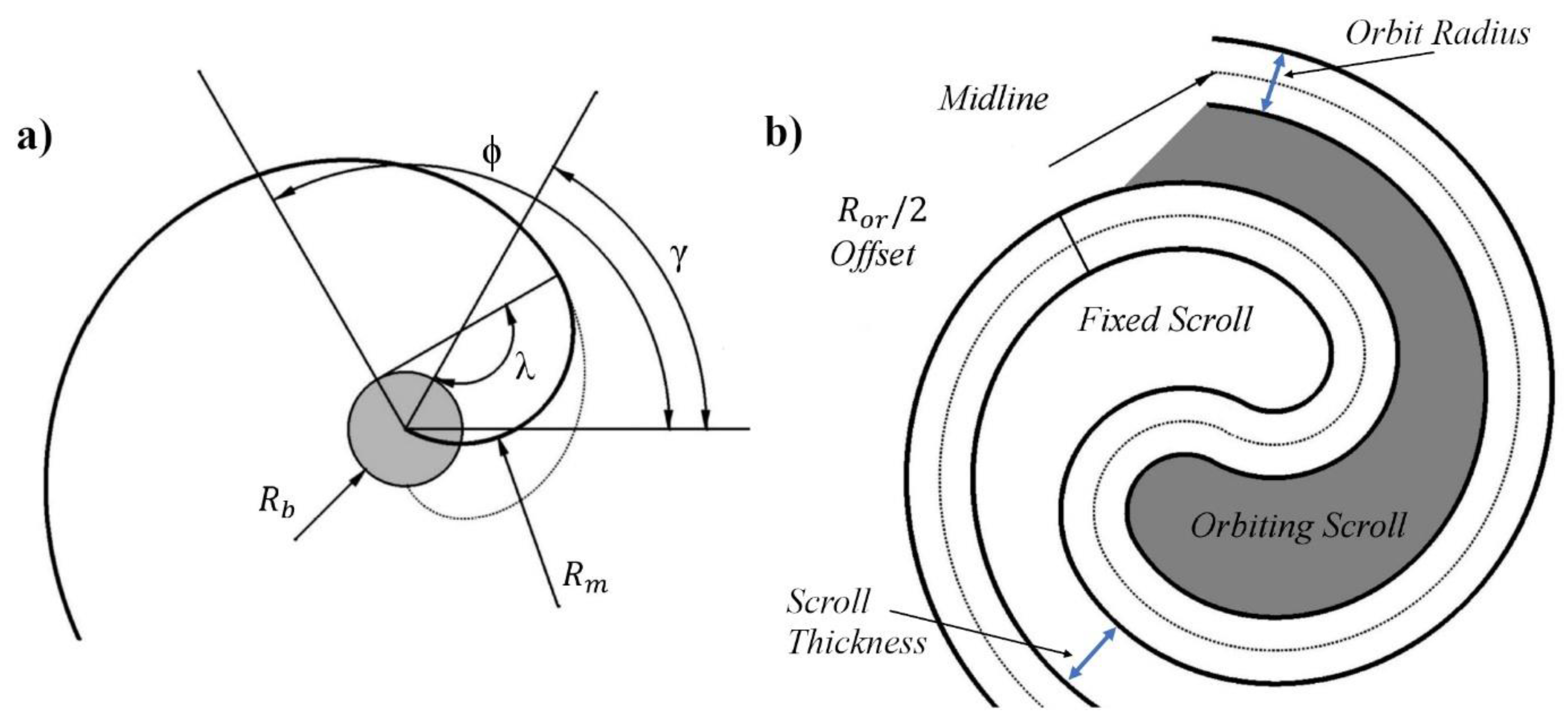
The scroll geometry, used in the test case, is defined according to the design procedure based on the equidistant curve approach. This procedure obtains the two spirals of the scroll as an offset of a continuous midline. It allows to define the complete meshing profiles (CMP) of the scroll, comprehensive of both the central and the peripheral profiles, simultaneously. This procedure was also adopted in [
29] thanks to the reduced number of equations to handle in the scroll design optimization procedure. Since it allows to control the clearance volumes and the flank gaps, it perfectly fits even in this study. Indeed, the scroll geometry is obtained by combining the design of the peripheral profiles (for example as the involute of a circle) with the Perfect Meshing Profile (PFM) technique. In this manner, the scroll profiles meshing in the center is improved and the gaps are limited to the maximum. On the other hand, the design procedure proposed by Wang et al. [
39] makes it possible from the very beginning to perfectly match the profiles even in the centers, in this way limiting further leakages due to imperfect profile interactions.
The midline of the proposed geometry is obtained by the combination of a circular involute with a circular arc (
Figure 1a) according to the following equations:
where (
,
) are the coordinates of the center of the circular arc while
Rm is the radius of the circular arc at the midline.
γ is the modified angle (angle between the center of the arc and the
x axis) while
λ is the central angle of the circular arc.
Rb is the radius of the involute generating circle while
φ and
are the starting and ending angle of the involute, respectively.
The two scroll profiles are then obtained by offsetting the midline in both directions by half of the orbit radius
Ror (
Figure 1b).
The design parameters of the scroll geometry are taken from Wang et al. [
39] since it is chosen as reference test case for evaluating the numerical model accuracy. The orbit radius
Ror is assumed equal to 5.5 mm, whereas the orbiting scroll is only translated by 5.47 mm, leaving a flank gap of 30 µm. The spirals have a thickness of 4.5 mm and a height of 40 mm with an axial gap of 50 µm. The discharge port is located at the scroll center, tangential to the fixed spiral at the final meshing point, with a diameter equal to 0.8 of the last pocket diameters.
3. Numerical Models
As stated above, there are three main meshing techniques able to handle the issue of the time-dependent mesh deformation typical of scroll machines. The aim of this study is not to discuss the strengths and the weaknesses of these techniques. Obviously, in literature, there are reviews and comparisons among them but not from a design point of view. In particular, if the problem is approached from a design procedure perspective, there is a need to focus on key geometrical details (i.e., the axial gap) and available numerical models. For this reason, the authors adopt the adaptive meshing technique, a consolidate meshing approach in PD machines analysis. Then, they compare the numerical approaches proposed by two commercial software, Pumplinx 5.0 [
40] and TwinMesh 2019 [
41], because they modelled the axial gap in a different way.
Twin Mesh is a grid generator specifically developed for rotary PD machines. It generates and optimizes the computational grids of the machine for each time step of the simulation. The step corresponds to a specific rotation angle of the rotor and, in general, the angle increment is assumed equal to 1° or 2°, as suggested by [
42,
43,
44]. This software is complementary to Ansys CFX 19.0 [
45] and allows to build the grids prior to the launch of the simulation. At the beginning of each time step, a proprietary Fortran routine [
41] loads the new mesh (depending on the rotor position) in the CFD solver and the mesh deformation is added to the set of differential equations. In this way, no interpolation is required between time steps; a technique that avoids the typical interpolation errors that occurred during the remeshing phase.
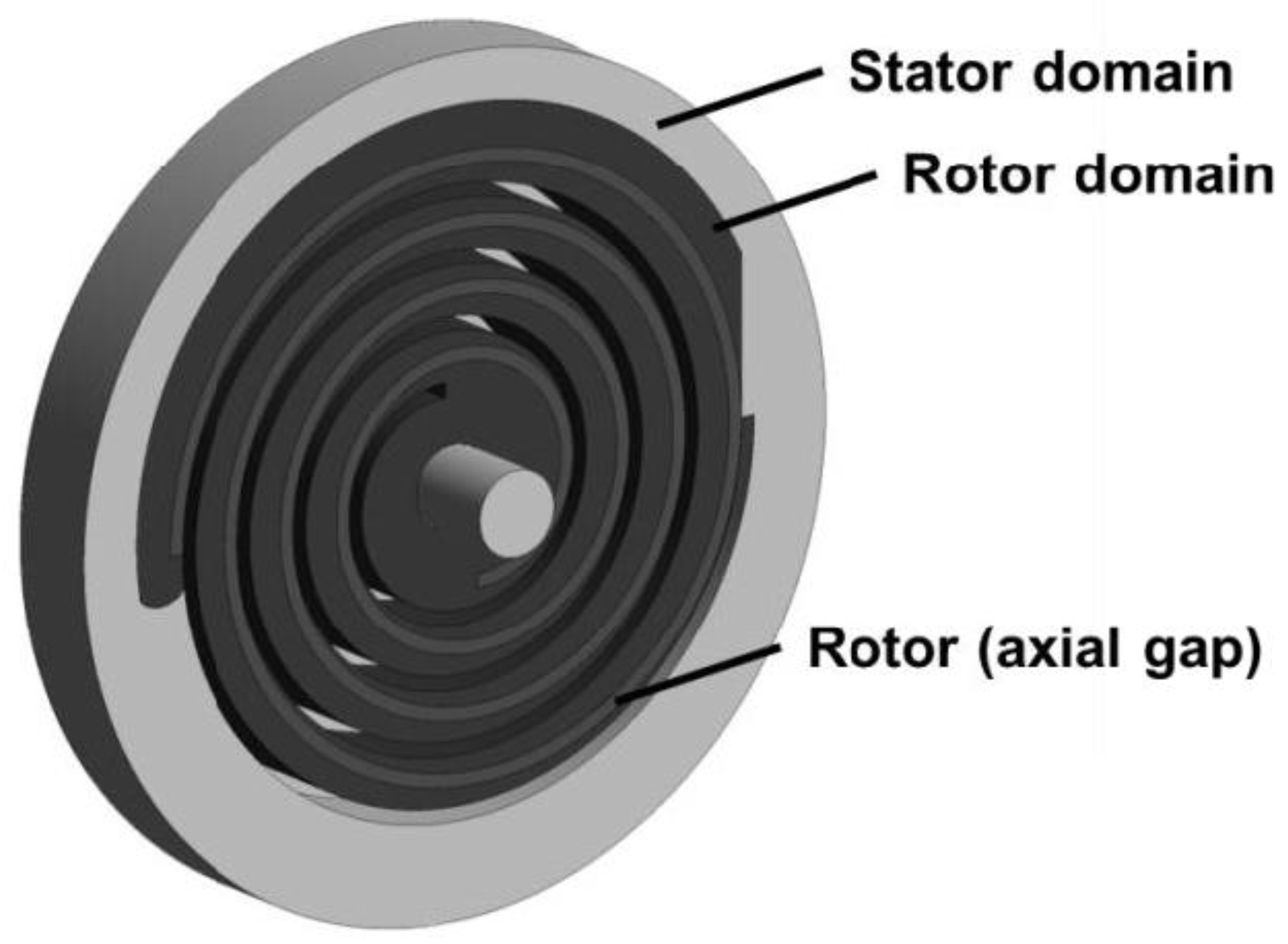
Twin Mesh allows to split the simulation domain into different volumes to apply the most suitable meshing strategy for each volume. In particular, a scroll geometry is subdivided in three main fluid domains: The stator domain (including inlet and outlet pipes and stationary parts of the working pockets), the rotor domain, and the rotor axial gap domain (
Figure 2). All the domains are meshed independently and connected in the simulation solver via a fluid-fluid Generalized Grid Interface (GGI) due to the time-dependent connection of the rotor domain with the stator one.
Regarding the rotor domain, affected by the time-dependent rotor movement, Twin Mesh adopts a 2D topology characterized by an O-type grid, characterized by hexahedral elements, around the rotor curvature. This grid is built for each possible rotor position adopting the same topology and node numbers as well as the same refined resolution boundary layers with higher aspect ratio towards rotor and housing walls. This is a precondition that guarantees to avoid the need of interpolations between time steps. Regarding the mesh quality, smoothing methods are applied to guarantee adequate quality values for the desired quality criteria (minimum element angle, aspect ratio, etc.). The 2D meshes are then extruded to obtain the 3D ones of the rotor domain.
The rotor axial gap is discretized by a structured high-resolution grid that allows to take into account the tip seal leakage flow caused by the gap.
The grids of the scroll geometry previously presented and generated by Twin Mesh [
41] are loaded in Ansys CFX 19.0 [
45] for carrying out a transient numerical simulation [
46]. As previously said, for each rotor position (defined by a rotation angle increment of 2°), the Fortran routine changes the rotor domain grid, loads the new one optimized for that specific position, but without interpolation needs.
Unlike Twin Mesh, which is a grid generator requiring the combination with the Ansys CFX solver, PumpLinx is a CFD software that allows, in a unique environment, to generate the grid, define the numerical model, and carry out the simulation.
As TwinMesh, PumpLinx automatically generates a structured mesh for both the stator and the rotor domains, but with a different meshing technique. For the rotor, it adopts the proprietary Conformal Adaptative Binary-tree (CAB) algorithm [
47], generating cartesian hexahedra cells in a volume enclosed by a group of surfaces. Close to the boundary, CAB automatically adjusts the grid shape to conform to the surfaces and critical geometry edges. In order to fit critical geometrical features, CAB modifies the cell size by progressive division of the mesh cells in half (binary grid).
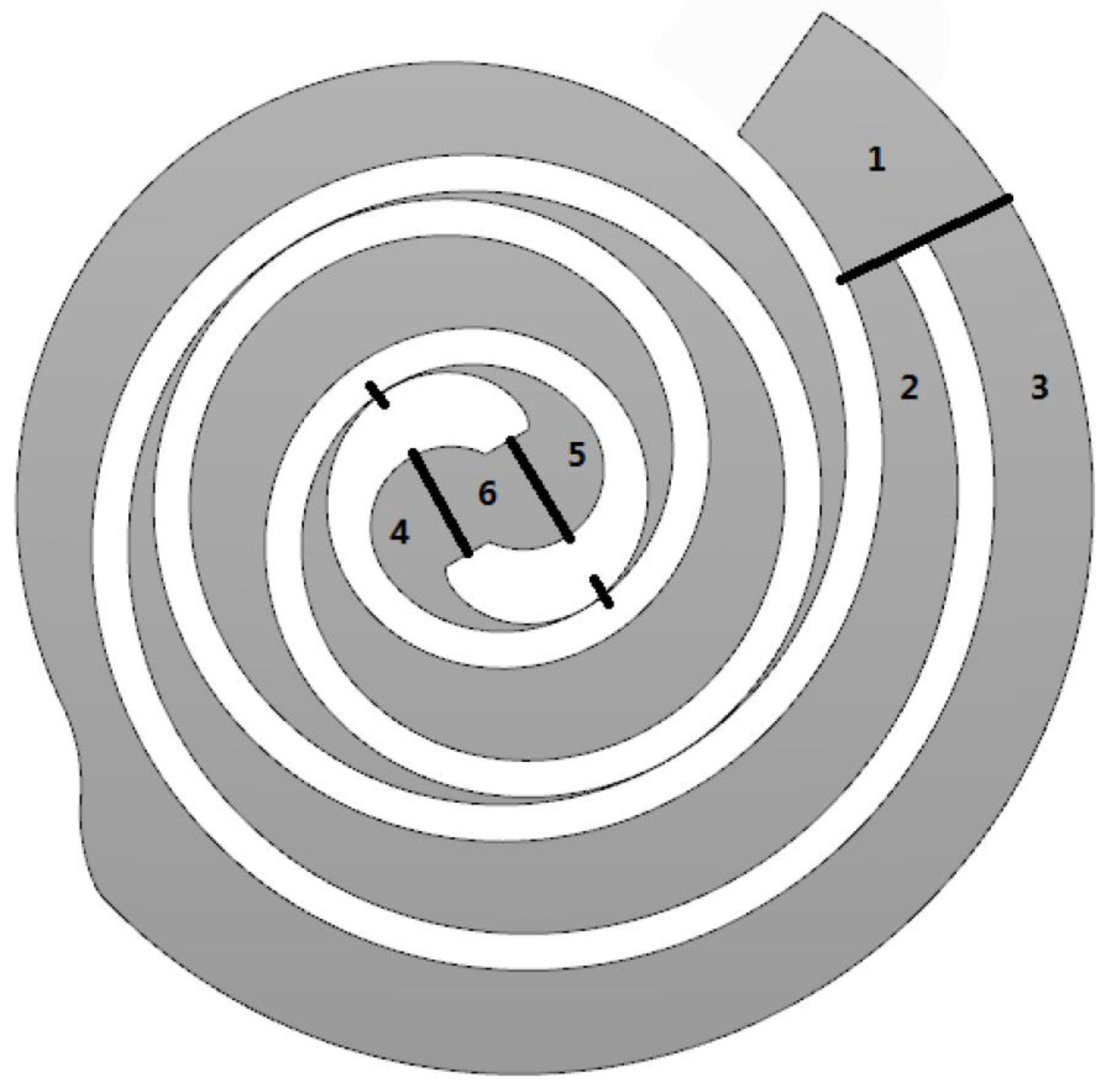
The rotor topology is cylindrical, and the automatic mesh generator adopts a multi-block strategy, searching for key geometrical points to subdivide the domain in six partitions (
Figure 3).
Partitions from 1 to 3 are meshed as long fluid volumes with evenly distributed nodes and hexahedral oriented in parallel with the rotor outline. Partitions from 4 to 6 belong to the central part of the scroll near the discharge port and allow the contact points. They are modelled as small gaps in agreement with all the other commercial software, Twin Mesh included. In these partitions, the grid is generated starting from lines of normal to solid walls so as guarantee a high level of orthogonality. Ecliptic smoothing techniques are adopted to optimize the grid in highly distorted areas (i.e., sharp corners), and a sweep method is applied. When the rotor moves into a new position, corresponding to a new time step, the procedure is repeated. More details on the meshing strategy in the discharge area are given in [
48].
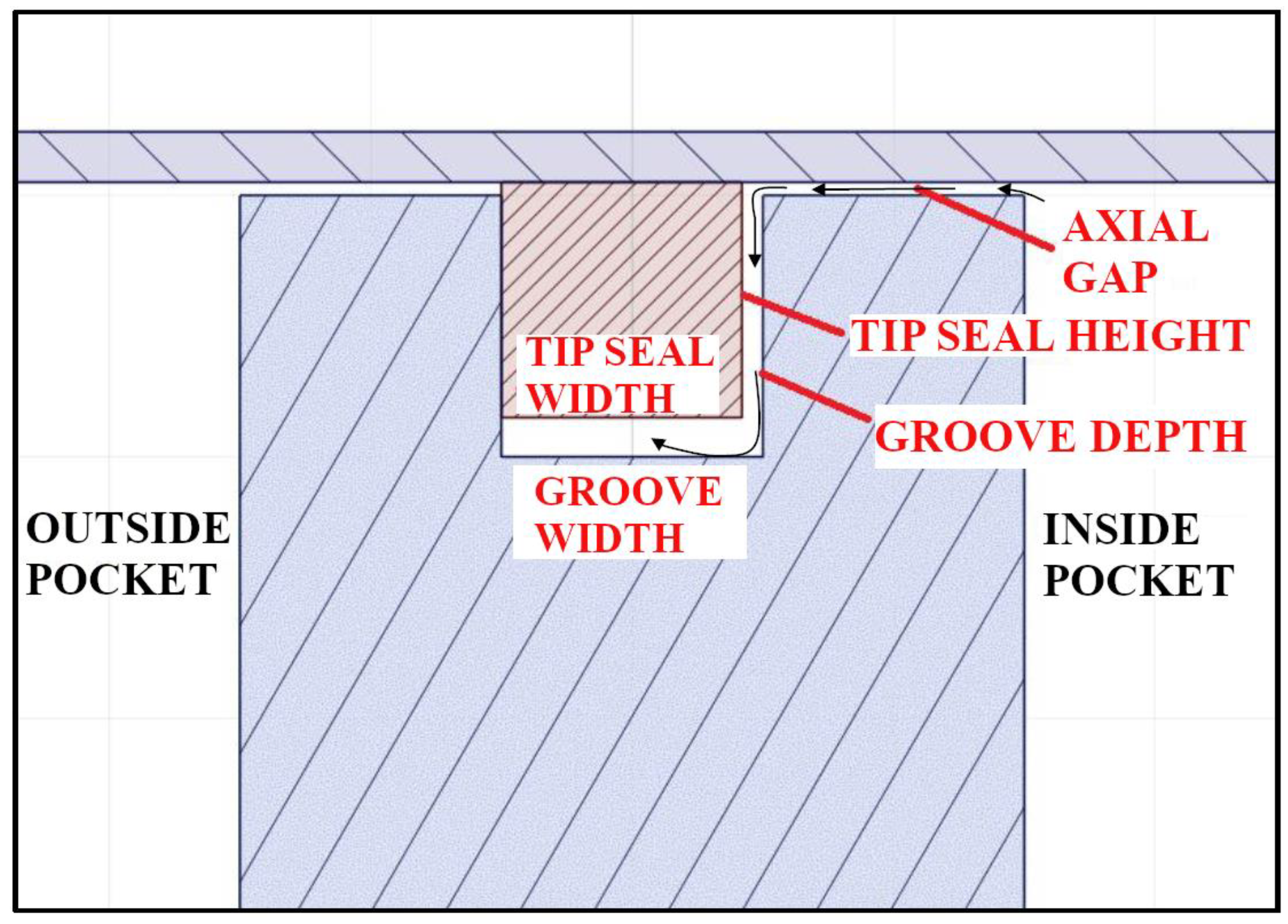
The main difference between this mesh generation procedure and the Twin Mesh one are regarding the axial gap, which is not considered, and is meshed as a separate high-resolution, structured grid. In PumpLinx, the leakage paths in the axial gap are not fully meshed. The reason is that the sealing action of the tip seal is assumed constant and perfect in time with a consequent null radial leakage flow in the axial gap (see
Figure 4).
Therefore, the leakage path is simplified in a Z-shaped fluid volume, which is meshed assuming the flux of mass, momentum, heat, and turbulence from one volume pocket to the other is null [
49]. This simplification assumes that the high-pressure value characterizing the inside pocket—in comparison with the low-pressure value in the outside pocket—continuously pushes the tip seal to the outer side of the groove, guaranteeing a perfect sealing (
Figure 4). Unfortunately, this assumption only partially reflects the real dynamics of the process. In fact, the real behavior is characterized by unsteady time-dependent reversals of the outside-inside pressure gradient. Moreover, it does not consider the inner imperfection in the sealing, due to the need for limiting the friction losses, a necessary condition for making the scroll movement possible. Lastly, the leakage volume stops at the ends of the spiral shape (
Figure 5).
The resulting fluid domain is certainly simplified since it forms a single computational domain with the tip seal volumes, and no flux of mass, momentum, heat, and turbulence from one volume pocket to the low-pressure one should be numerically solved [
49].
To analyze the influence of these two different meshing strategies on the numerical viewpoint, particular attention needs to be paid to avoiding the influence on the results of the third factors. First, a sensitivity analysis based on the average inlet mass flowrate is carried out with and without the axial gap for both software, resulting in the number of nodes reported in
Table 1.
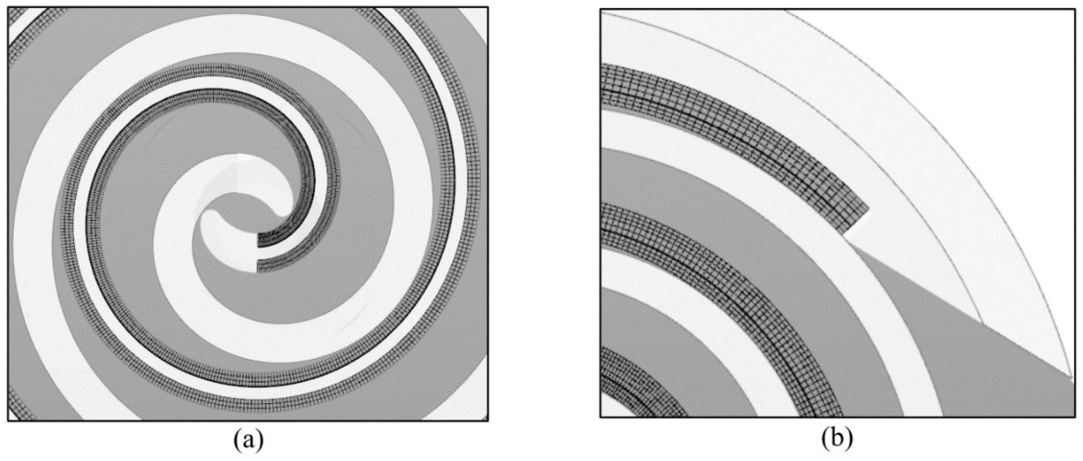
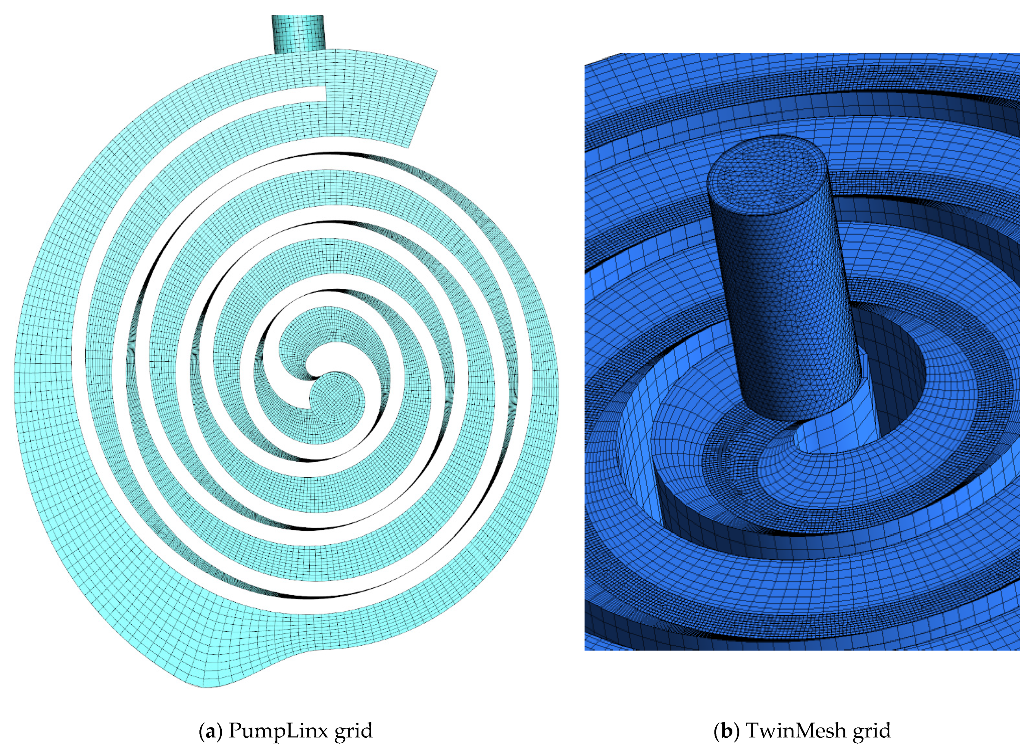
The resulting number of elements for the main fluid domain is similar in both cases with an equal number of elements per dimension (
Figure 6). For example, in the case without an axial gap, the following node distribution is fixed for both software: 180 elements in the θ-direction, 12 elements in the radial direction, and 10 elements in the axial direction. In the case considering the axial gap, the differences in the total number of nodes are mainly due to the different strategy for modelling the gap (
Figure 6b).
The settings of the reference test case [
39] are also fixed in both cases. In particular, a pressure ratio of 7:1 (
pin = 1 bar,
pout = 7 bar) with a rotation rate of 3000 rpm is fixed. The fluid is assumed to be an ideal gas with constant properties (
Tin = 293 K) beside the density.
Regarding the solver scheme, a high-resolution, second-order scheme (Upwind for PumpLinx and Backward Euler Transient for CFX) is adopted in both cases with first-order turbulence numeric [
49]. The time step is fixed equal to a rotation angle increment of 2°.
The turbulence is considered with a Shear Stress Transport (SST) turbulent model in CFX, whereas with a k-ε model in PumpLinx, since neither the SST nor the k-ω are available for this software. However, it must be pointed out that the k-ε model is the state-of-the-art turbulence model in CFD simulations carried out on scroll geometries, as it is clearly highlighted in Table 6 of [
5] and confirmed by the most recent CFD studies on scrolls [
35,
36]. So, the difference in turbulent model is considered useful to evaluate the accuracy of the k-ω model in comparison with the state-of-the-art k-ε approach. No-slip wall condition is fixed on the walls.
The simulations are performed over a total of five complete revolutions of the scroll rotor. The scroll fluid dynamics reaches convergence after two, or maximum three, revolutions.
4. Results and Discussion
This section presents the results of the simulations carried out with the two approaches and discusses their strengths and weaknesses in the analysis of a scroll compressor.
As said, the two approaches differ not only in the modelling/meshing strategy of the axial gap, but also in the turbulence model. All these differences in the approach are the result of the different “philosophy”, underpinning the development of the two software. On one side, the CFX approach is inherently aimed at reproducing as much accuracy as possible in the machine flow field, searching for a high level of adherence to the real geometry, even at gap level, and to the multi-scale fluid dynamics. On the other side, the PumpLinx software aims at reproducing the macro aspects of the scroll fluid dynamics, prioritizing the adoption of simplified and time-saving modeling solutions.
To capture the influence of these two approaches on the results, the comparison between them is carried out at different levels (from macro- to micro-scale) and for different models (with and without axial gap) and the resulting accuracy in comparison with the experimental results is evaluated.
4.1. Scroll Simulation without Axial Gap
The scroll fluid dynamics is extremely complex and characterized by several unsteady phenomena whose development is strictly related to the so called “porting process”, i.e., the suction and discharge process of the fluid mass flow.
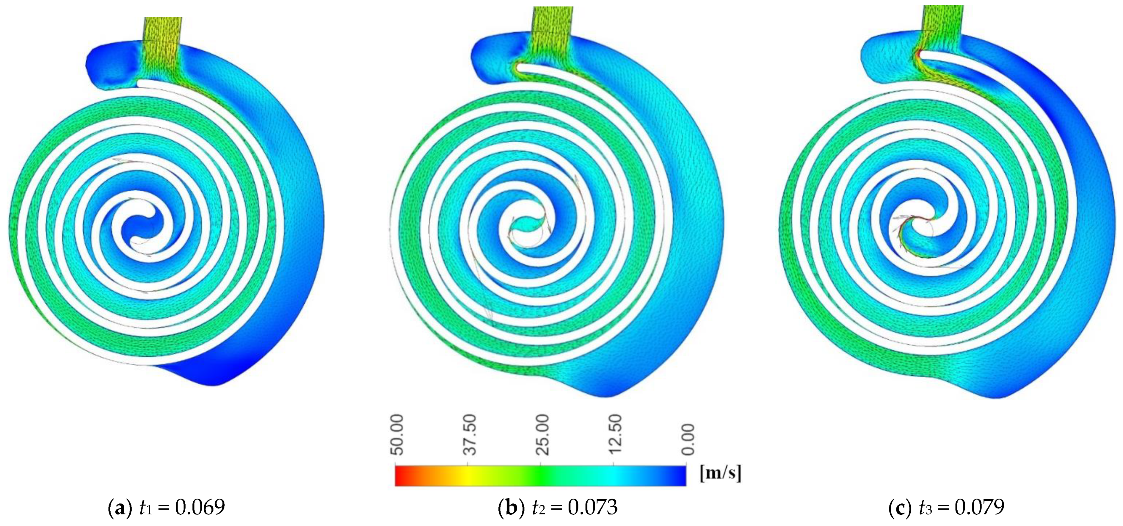
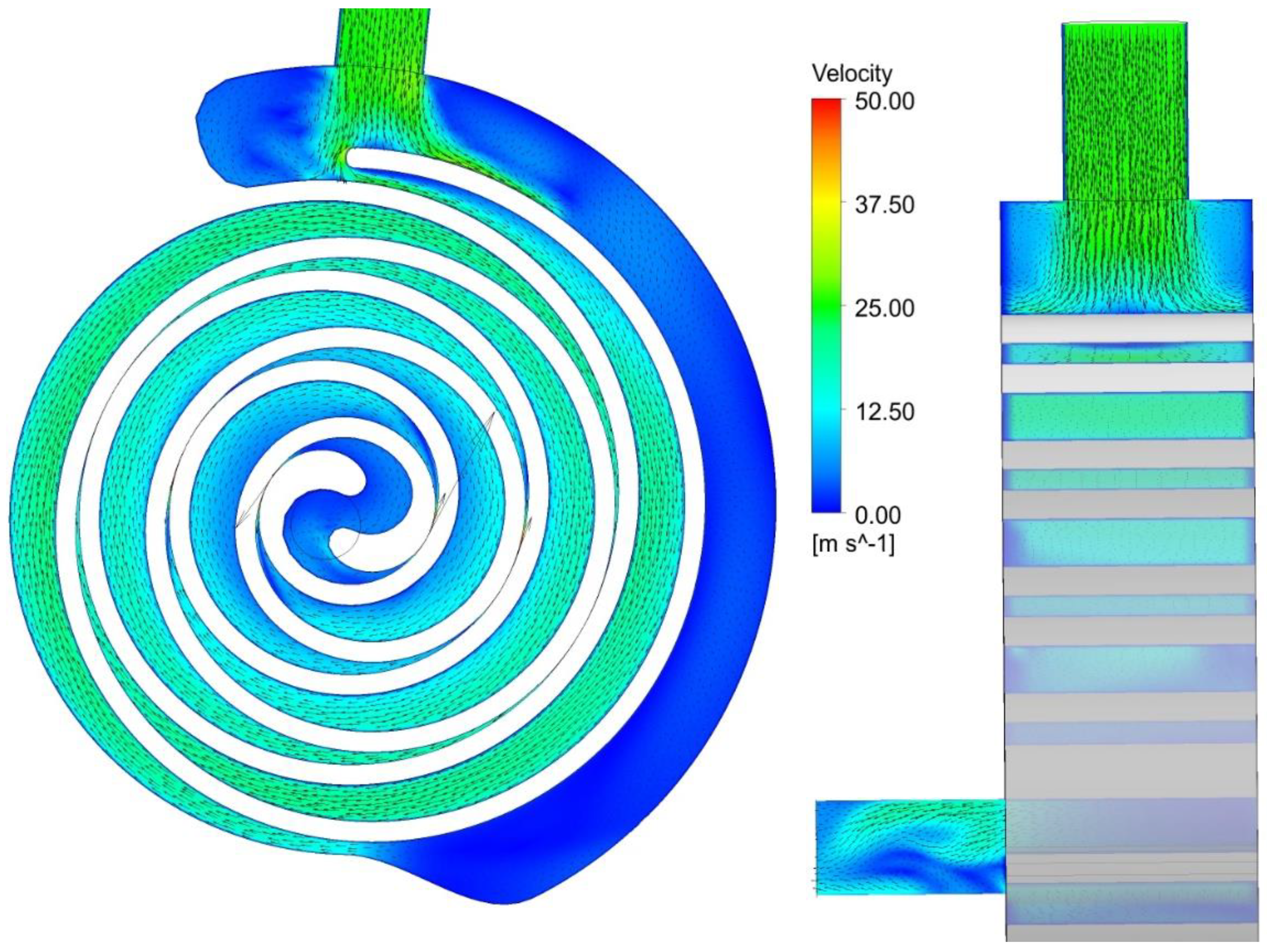
Figure 7 and
Figure 8 show the vector plots, captured by CFX, in two different sections of the scroll (mid-span and axial) for three different instants during the last revolution (
Figure 9—1 revolution = 0.02 s).
At
t1 the orbiting scroll is located farthest from the inlet port (
Figure 7). The filling of the inlet pocket is just started, and the instantaneous mass flow rate is close to its peak value (
Figure 9). Large recirculating zones are induced by the interaction between the mass flow entering in the inlet pocket and the outside wall of the orbiting scroll. This interaction forces the flow to reverse direction giving rise to vortexes, clearly affecting the flow field near the inlet duct (
Figure 7). The vortexes extend for the whole radial direction and involve half of the pocket width (
Figure 8).
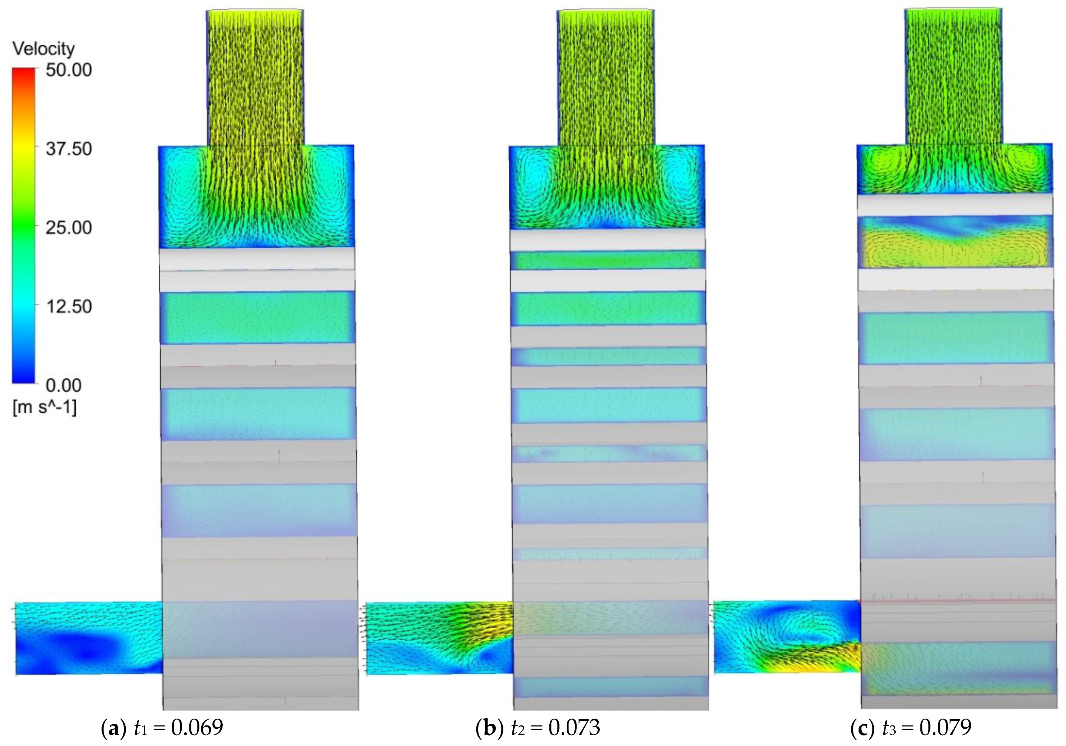
The location of the inlet port in front of the orbiting scroll continuously modifies the radial distance between the inlet port and the moving wall of the orbiting scroll, reproducing the unsteady “tumble” phenomenon typical of the internal combustion engines. Indeed, as shown in
Figure 8, the surface of the orbiting scroll moves towards the inlet port, reducing the radius of the vortexes whose rotation rate is consequently increased to maintain their constant moment of momentum (net of the losses). In the second part of the suction phase, the outside surface of the scroll moves away from the inlet port, increases the vortexes radius, and hence, progressively decreases their intensity (
Figure 9). This phenomenon is further amplified by the progressive reduction of the inlet mass flow rate. When the mass flow rate reaches its minimum (
in
Figure 9), the vortexes almost disappear (
Figure 10).
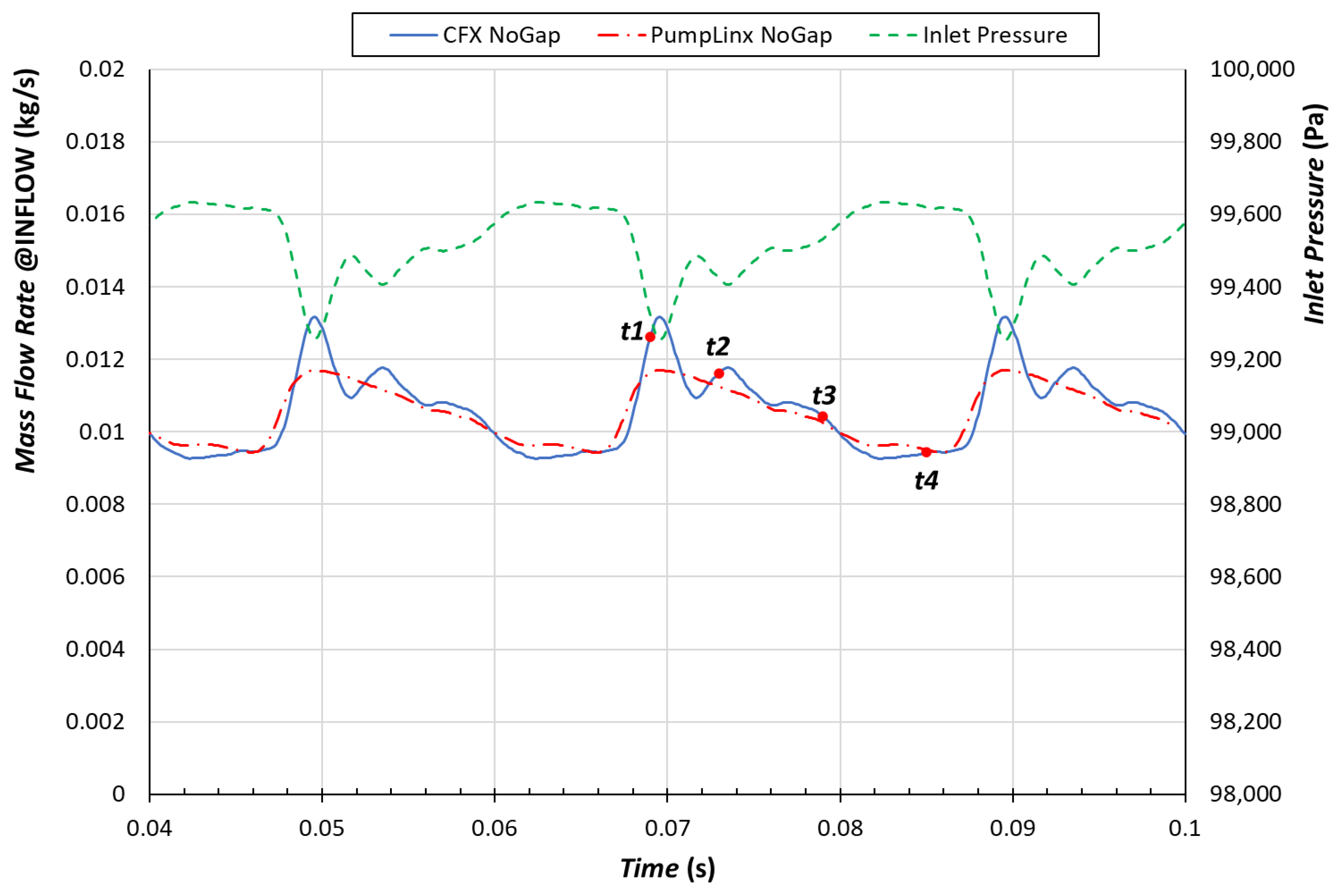
Figure 9 also depicts the evolution over time of the inlet mass flow rate captured by PumpLinx. The general trend is to some extend similar. The average value of the mass flow rate is almost equal in the two simulations: 0.010553 kg/s in CFX vs. 0.010483 kg/s in Pumplinx, and approximate with a sufficient accuracy (an error less than 5%) the experimental mass flow rate
[
39]. However, CFX captured a greater peak value of the mass flow rate (+24% for CFX vs. +11.6% for Pumplinx with respect to the average value) and a pulsating behavior, amplified in the first part of the suction phase (from time 0.69 to 0.73). This pulsating behavior, whose frequency is half of the machine rotation frequency (25 Hz vs. 50 Hz corresponding to a period of 0.04 s vs. 0.02 s), is clearly linked to the perturbation of the inlet pressure (
Figure 8). As given below, the perturbation seems provoked by the inertia phenomena developing in the discharging pockets, which causes pressure drops propagating up to the scroll inlet.
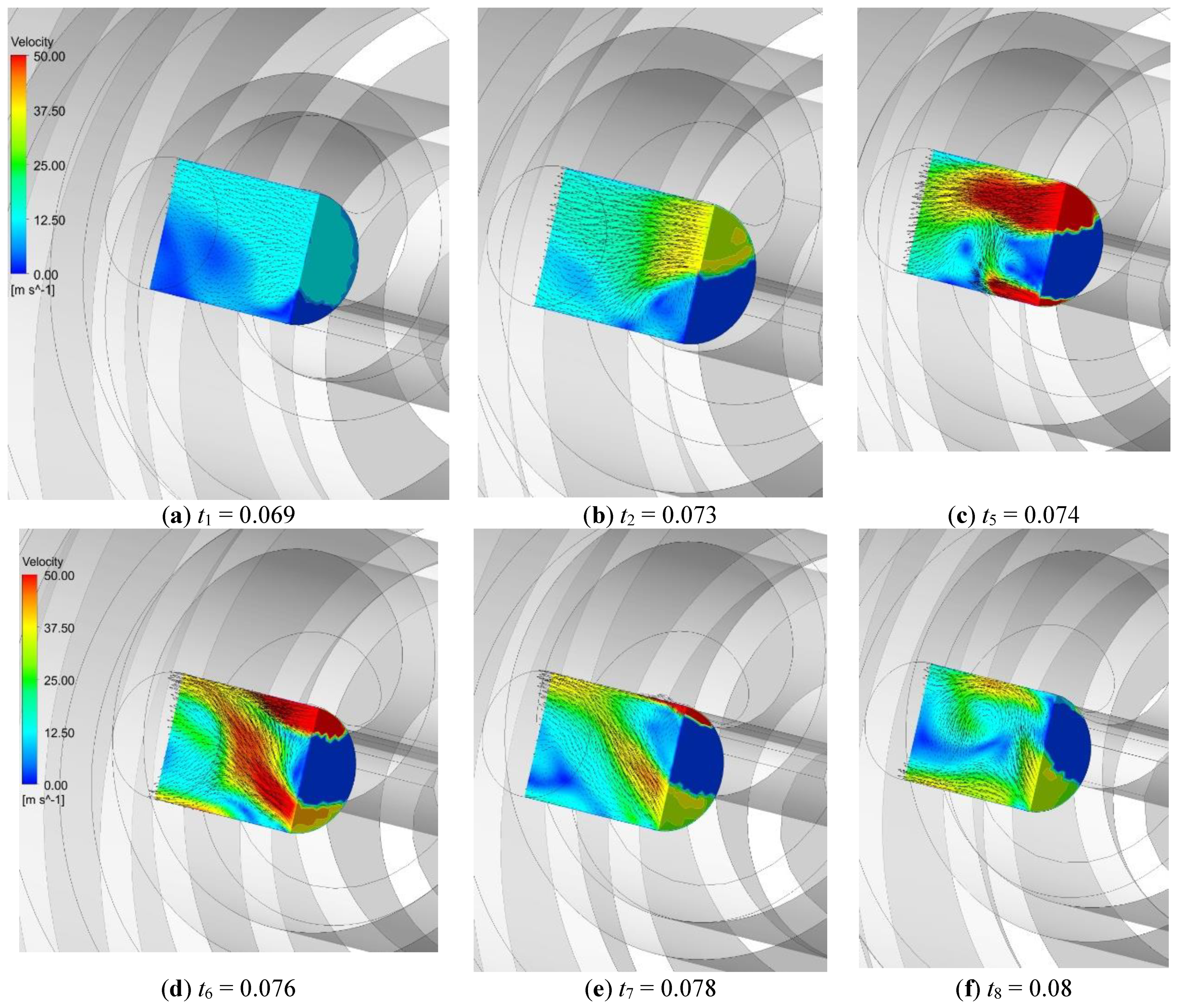
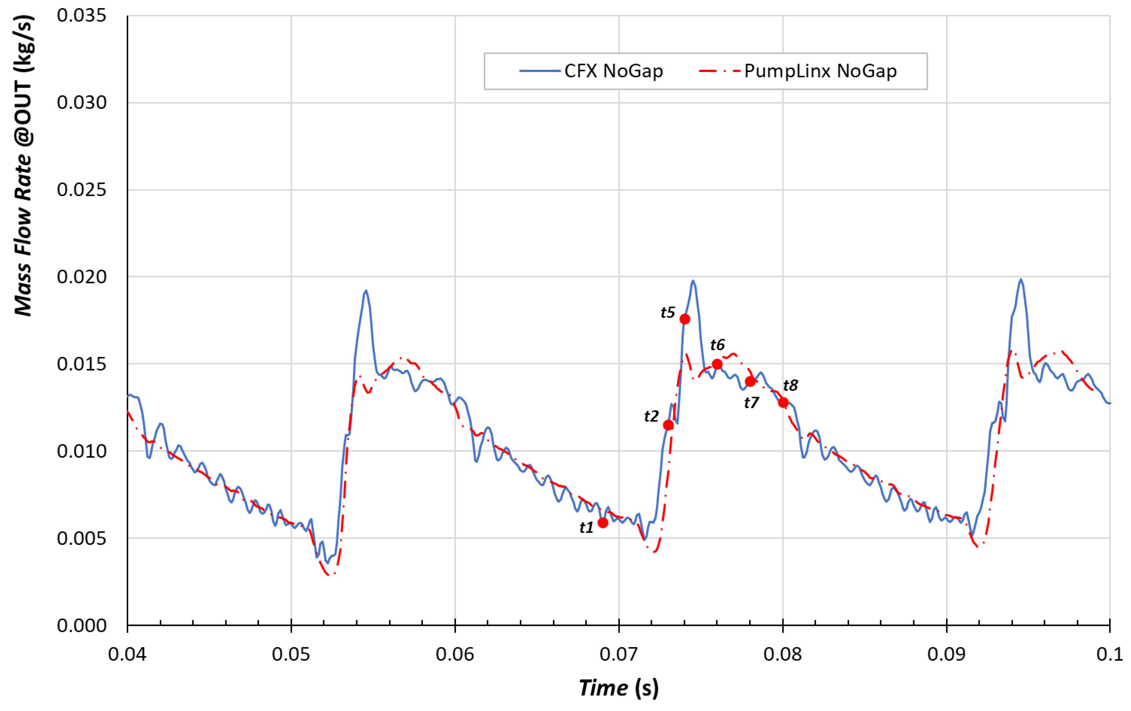
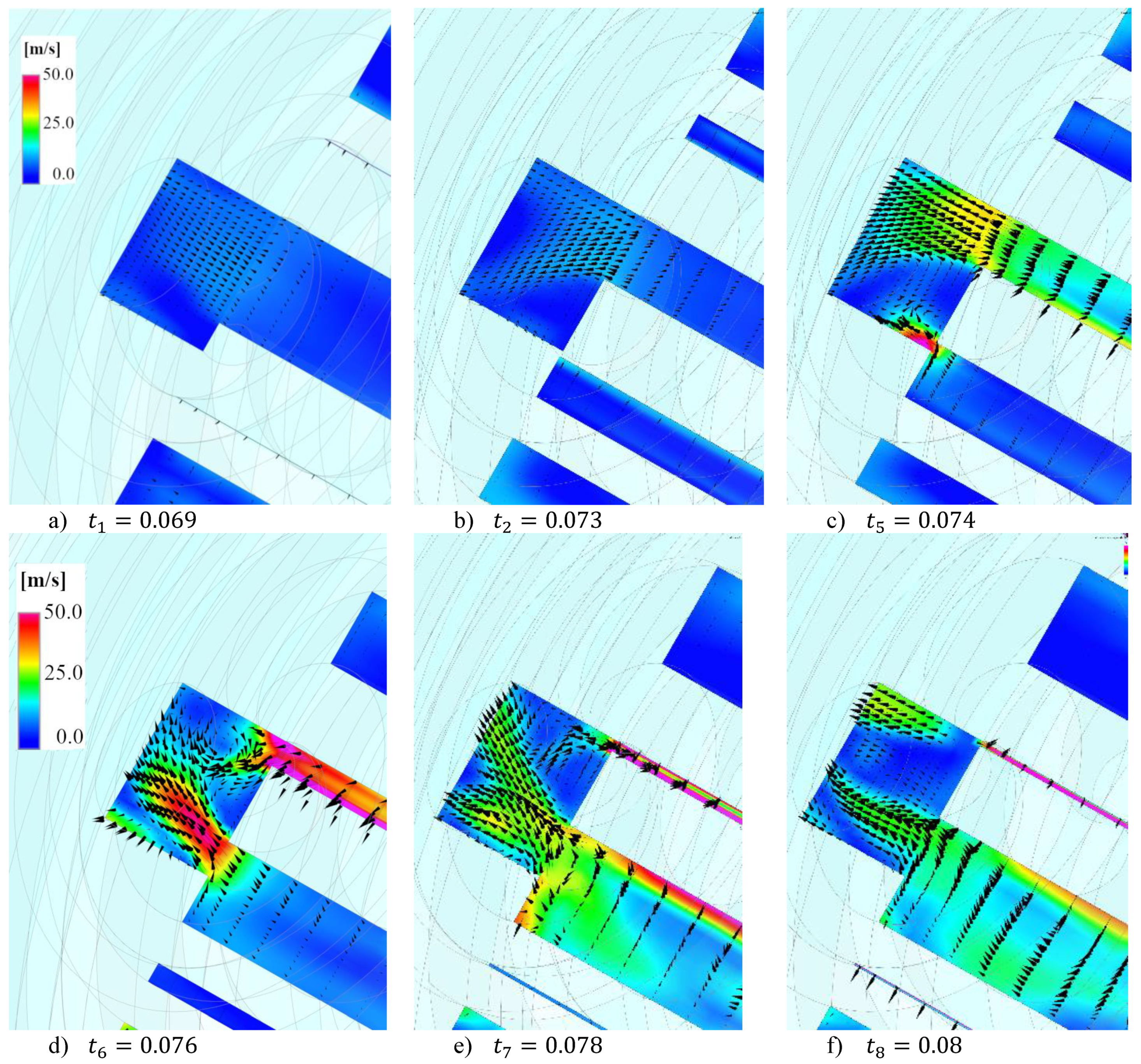
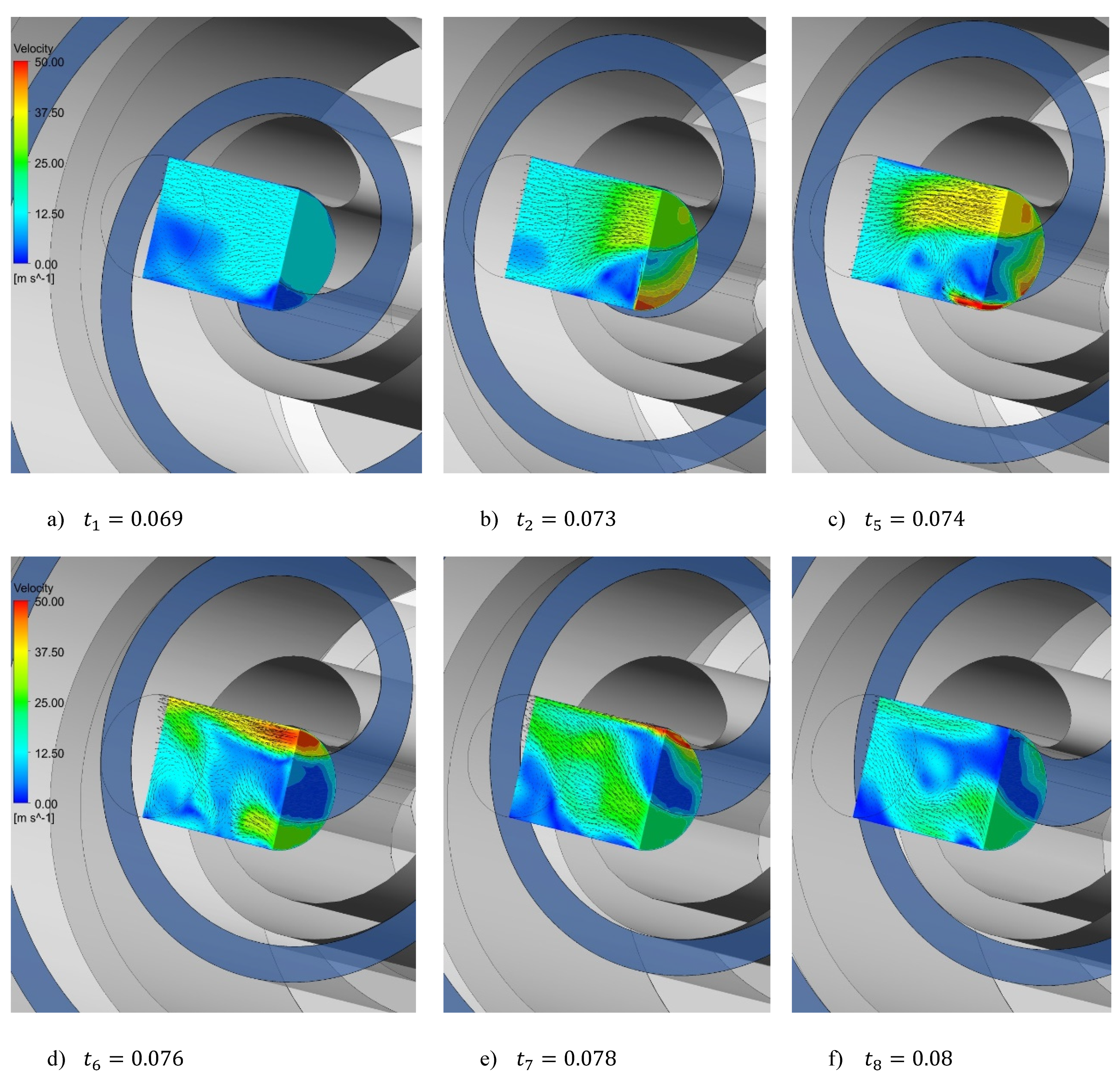
Figure 11 depicts the vector plots of the flow field at the scroll discharge on two different locations. The first section plan is normal to the scroll axis and coincides with the discharge port, while the second one is the same axial section plane of
Figure 7 with a view limited to the discharge area. The vector plots refer to six different instants which are also highlighted in
Figure 12, reporting the evolution over time of the outlet mass flow rate, as determined by CFX (solid line) and PumpLinx (dash-dot line).
In t
1, the scroll has almost concluded the discharge of the fluid mass (
Figure 12) and the flow field does not present vortexes or separation zones (
Figure 11). Then, the remaining fluid mass of the last pocket is progressively pushed out from the discharge port by the movement of the orbiting scroll. This movement indeed causes, at the same time, the reduction of the volume of the discharging pocket and the start of the discharge of the second last pocket (see
t2 and
t5 in
Figure 11). The mass flow discharged by the scroll significantly increases due to this double contribution, reaching its peak, and then decreasing while the scroll completely opens the discharge port (see
t6,
t7, and
t8 in
Figure 11).
This analysis highlights two interesting fluid-dynamic phenomena:
During the first part of the discharge phase, the flow field is perturbed by jets of mass flow coming out from pressurized discharging pockets (see
t5 and
t6 Figure 11). These jets are combined with counter-rotating vortexes and separation zones. This behavior explains the main peak and the subsequent smaller one in the evolution of the outlet mass flow rate (
Figure 12), due to the combined discharge of the two pockets (see
t5 and
t6 in
Figure 11).
The discharging process is characterized by inertia phenomena, affecting the pressure level in the discharging pockets. At the beginning of the discharge phase, the pressurized discharging pockets push out the fluid mass, with a consequent rapid decrease in local pressure (
Figure 13). This pressure drops reasonably to propagate up to the inlet suction pocket through the radial clearance, providing an explanation for the trend of the inlet pressure and mass flow rate in the CFX analysis (
Figure 9).
Clearly, PumpLix is able to capture the main characteristics of the flow field development in the scroll (
Figure 14). However, there are some discrepancies that can justify the slightly different trend of the instantaneous mass flow rate. For example, at t
5 the mass flow discharged by the last pocket is less intense (
Figure 14), resulting in a smaller peak in
Figure 12. At
t6 the two jets of mass flow and the main vortex are captured but the structure of secondary flows developing in the discharging duct is less defined, resulting in a more regular discharge of mass flow at the scroll outlet. Despite the general agreement in trends between the software,
Figure 12 clearly shows that CFX captured a more perturbed evolution over time, in line with the extremely unsteady flow field at the scroll discharge.
The main reason for this difference seems to be the turbulent model. As previously highlighted, PumpLinx adopts the k-ε model, which is widely used in the prediction of several turbulent flow calculations due to its robustness, economy, and reasonable accuracy for a wide range of flows. However, it has been also demonstrated that this model performs poorly when faced with non-equilibrium boundary layers as in the case of “tumble” motion at the entrance [
50].
In this case, the k-ε model is not able to properly capture the unsteady phenomena affecting the scroll fluid dynamics. Therefore, the mass flow rate peaks are underestimated and the mass flow rate at the scroll inlet presents a more regular trend (
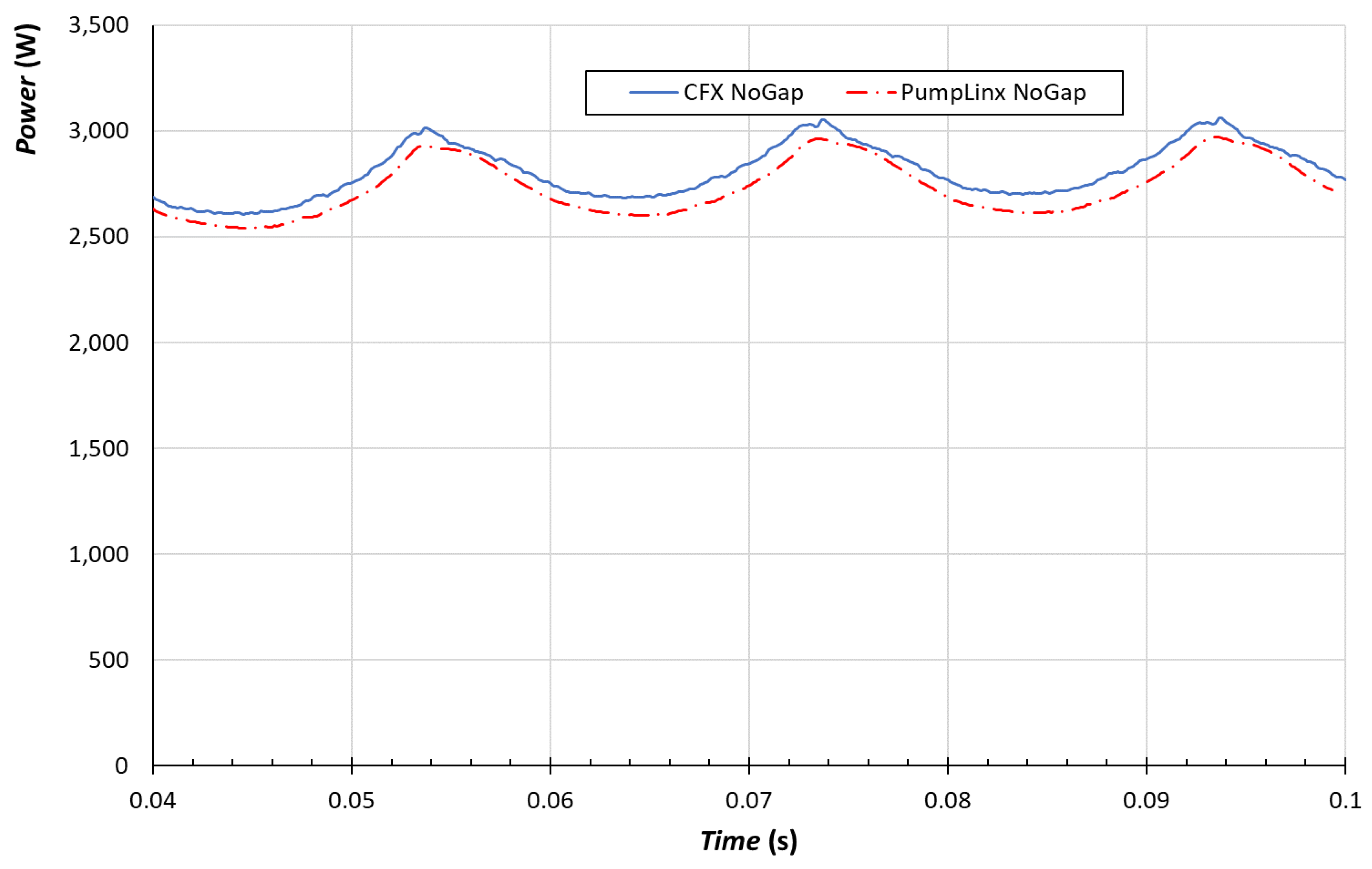
Figure 9). Regarding the power absorbed at the scroll shaft, PumpLinx determines a smaller power in comparison with CFX (
Figure 15). This seems mainly linked to the underestimation of the fluid-dynamic losses associated with the unsteady phenomena developing within the scroll, which are not completely captured by PumpLinx.
In summary, when the axial gap is neglected, the comparison between the modelling strategy adopted by the two software highlights that the combination between Twin-Mesh and CFX allows a more accurate overview of the fluid dynamics within the scroll machine. In this regard, the turbulence model (for example the SST model) plays a key role in the case of flow fields characterized by separation zones and unsteady phenomena, such as the jets of mass flow rate previously discussed. The in-depth evaluation of the flow field makes it easier to identify the geometrical details affecting the scroll performance. For example, CFX allows to highlight the influence of the inlet port location on the trend of the instantaneous mass flow rate. However, it must be pointed out that the average values of the main performance parameters are comparable for the software, but the simplified modelling strategy proposed by PumpLinx allows to reduce the computational time. This can be a benefit when the CFD simulation is included in an optimization procedure, requiring hundreds, if not thousands, of simulations. In this case, average performance values characterized by sufficient accuracy can represent a good compromise between accuracy and computational time. To stress this time-saving approach, the simulation of the scroll is repeated adopting a first-order solver scheme in PumpLinx, further speeding up the computing process. The development of the main flow field is sufficiently captured even in this case. However, the accuracy of the average values is reduced. In fact, the average mass flow rate decreases from 0.010485 kg/s to 0.010012 kg/s, increasing the numerical error—with respect to the experimental value—up to 9%, whereas the absorbed average power is overestimated (from 2.75 kW to 3.23 kW).
4.2. Scroll Simulation with Axial Gap
Another key aspect to consider in the analysis of a scroll and, more generally, of a volume displacement machine is the axial gap modelling. Experimental studies clearly demonstrated that the relevance of the axial gap is even greater than that of the radial gap due to the longer sealing length [
30,
31]. So, depending on the CFD goals, it is extremely important to define the appropriate modelling strategy to consider the axial gap.
As given in
Section 3, TwinMesh and PumpLinx adopt two different strategies for the axial gap modelling. The first one makes it possible to consider the radial leakage through the axial clearance. The other one models the gap as equipped with perfect tip seal, preventing the radial leakage from pockets, and allowing only the tangential leakage along the wrap in the tip seal (
Figure 4).
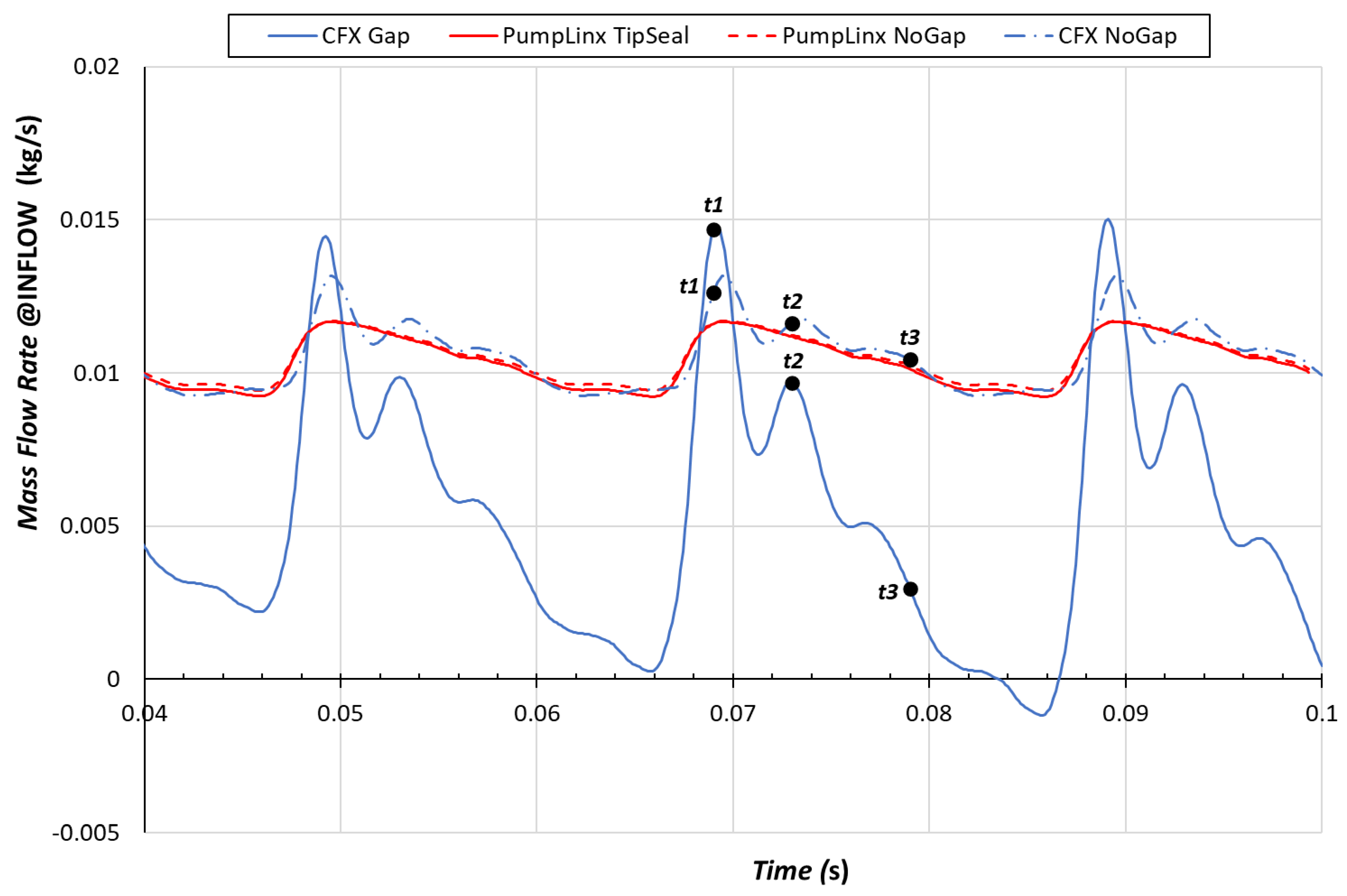
The difference in the two modelling approaches can be appreciated by the result comparison.
Figure 16 shows the instantaneous inlet mass flow rates as a function of time in four different cases: CFX with axial gap (blue solid line), CFX without axial gap (blue dash-dot line), PumpLinx with the perfect tip seal (red solid line), and PumpLinx without axial gap (red dash-dot line).
There is no significant difference in results between the PumpLinx cases with and without axial gap. The perfect seal prevents radial leakages in the axial gap from the compressed pockets back to the suction area. The average mass flow rate is only slightly reduced (0.01038 kg/s vs. 0.01048 kg/s) and the reason of this reduction is the increase in tangential leakage, gaining the small contribution of the leakage tangential flow in the tip seal.
On the other side, in the CFX results, the mass flow rate pulsation, also experienced in the case without axial gap (
Figure 9), is significantly amplified by the introduction of the axial gap.
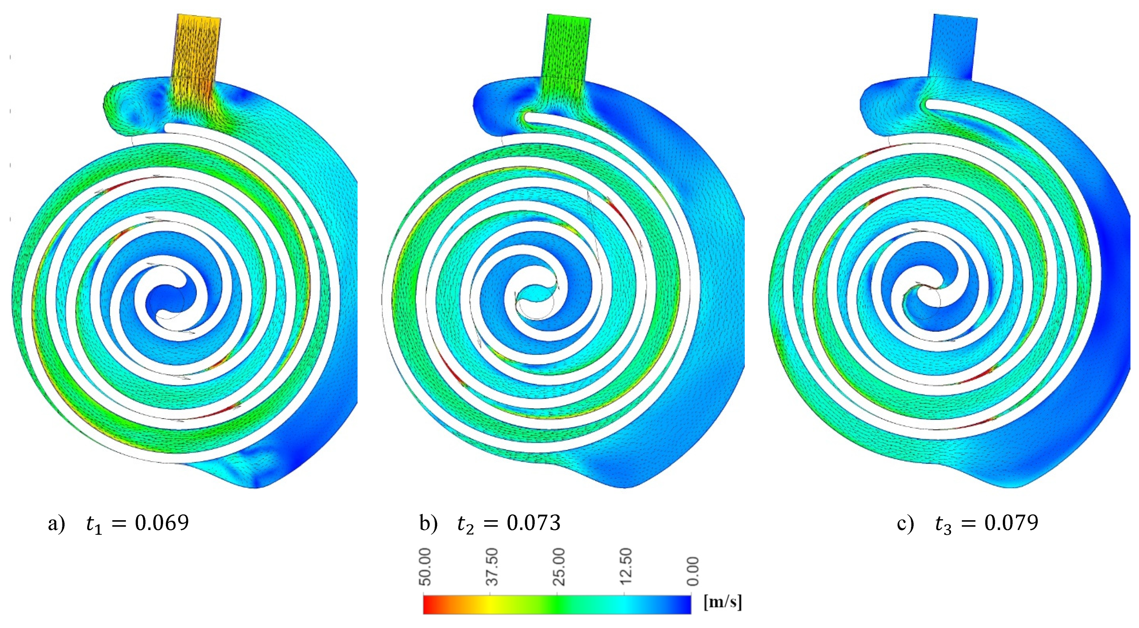
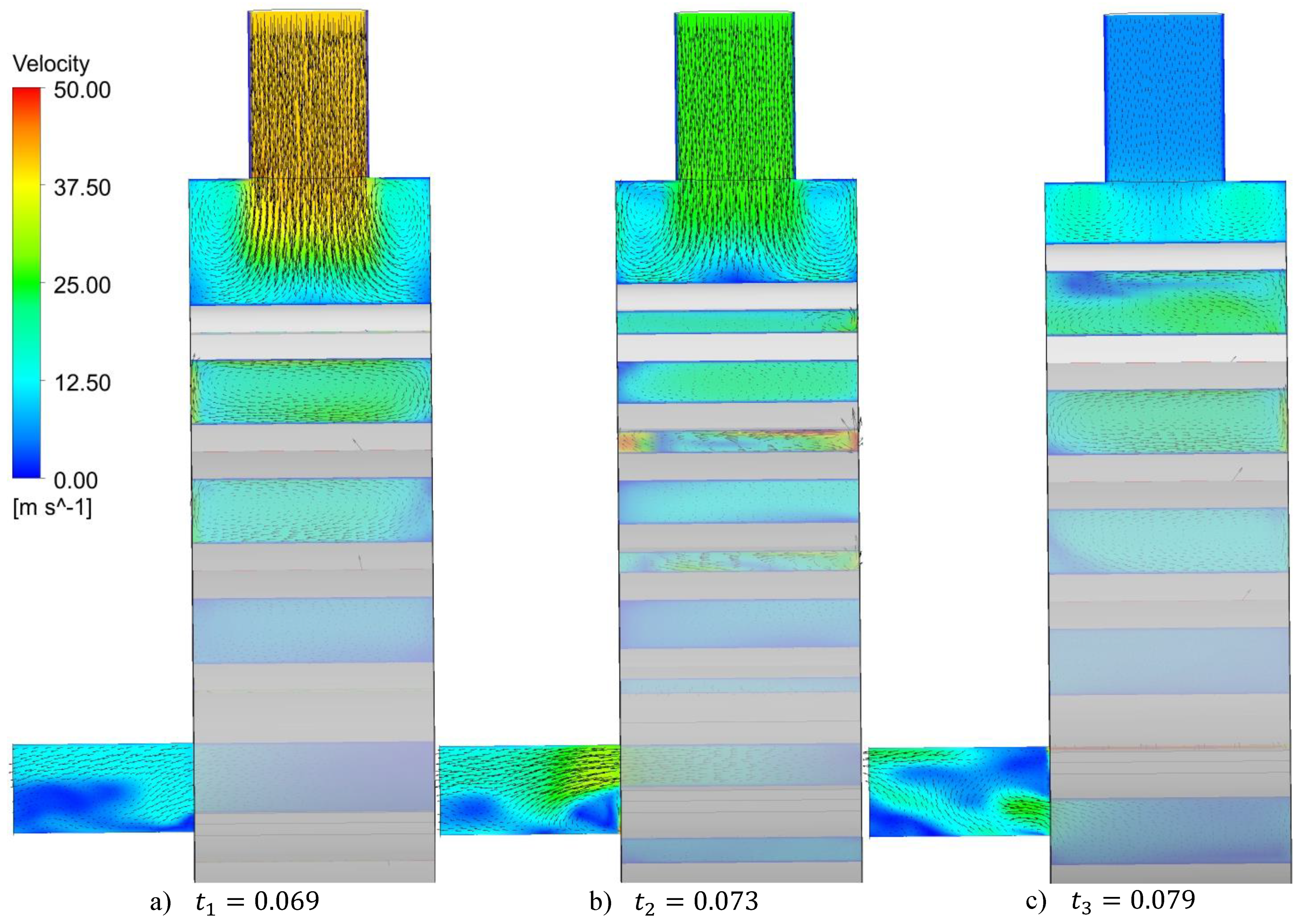
The flow fields reflect this behavior since they change significantly during one revolution of the scroll (
Figure 17 and
Figure 18). At the beginning, t
1, the velocity at the entrance reaches values around 40 m/s while the flow rate is so intense to be deviated by the wall of the orbiting scroll, creating two side vortexes close to the inlet duct (
Figure 16). Then, the flow rate progressively decreases during the revolution, reaching values close to zero (
t3). The flow field within the suction pocket is characterized by velocity close to zero, and even the tumble motion, linked to the flow rate entrance, almost disappears (
Figure 18).
This is due to the radial leakage in the axial gap (not considered in the PumpLinx cases), moving back from discharge up to the scroll inlet pocket. When this flow leaks from a high-pressure pocket to a low-pressure pocket, its pressure content slightly pressurizes the low-pressure pocket. This is of course a dynamic process that is strictly linked to the instantaneous evolution of the pressure within the pockets during one revolution of the scroll.
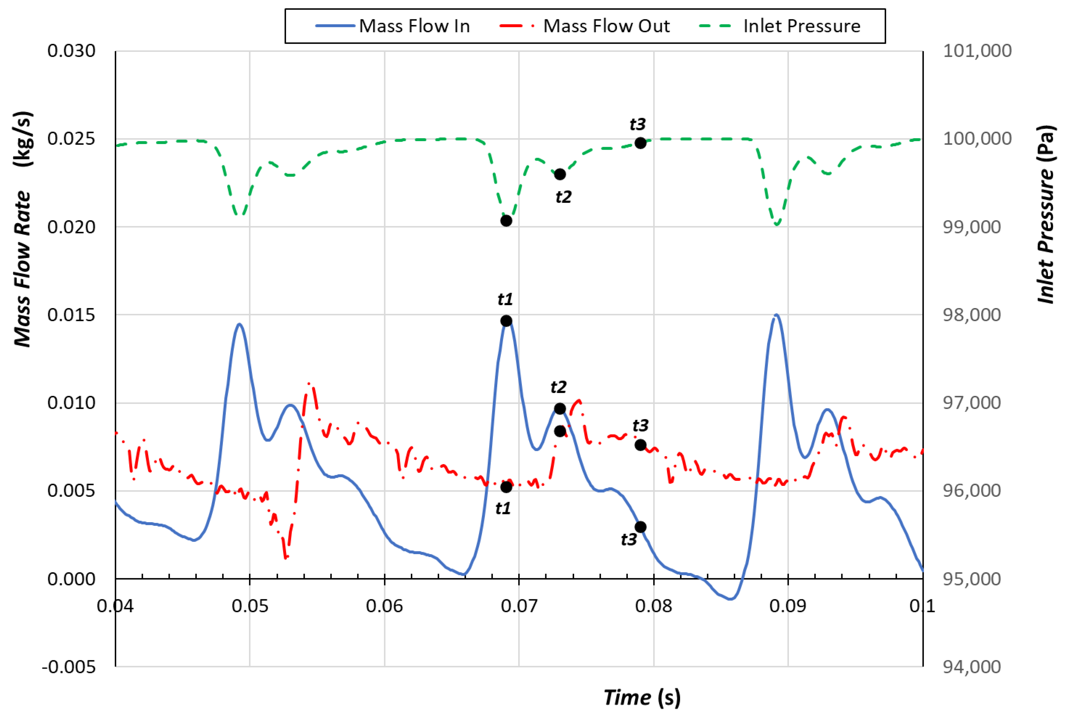
To better clarify this process and the interconnections between factors, it is mandatory to compare the evolution over three cycles of the instantaneous mass flow rate at the inlet and outlet ports with the pressure at the inlet port (
Figure 19).
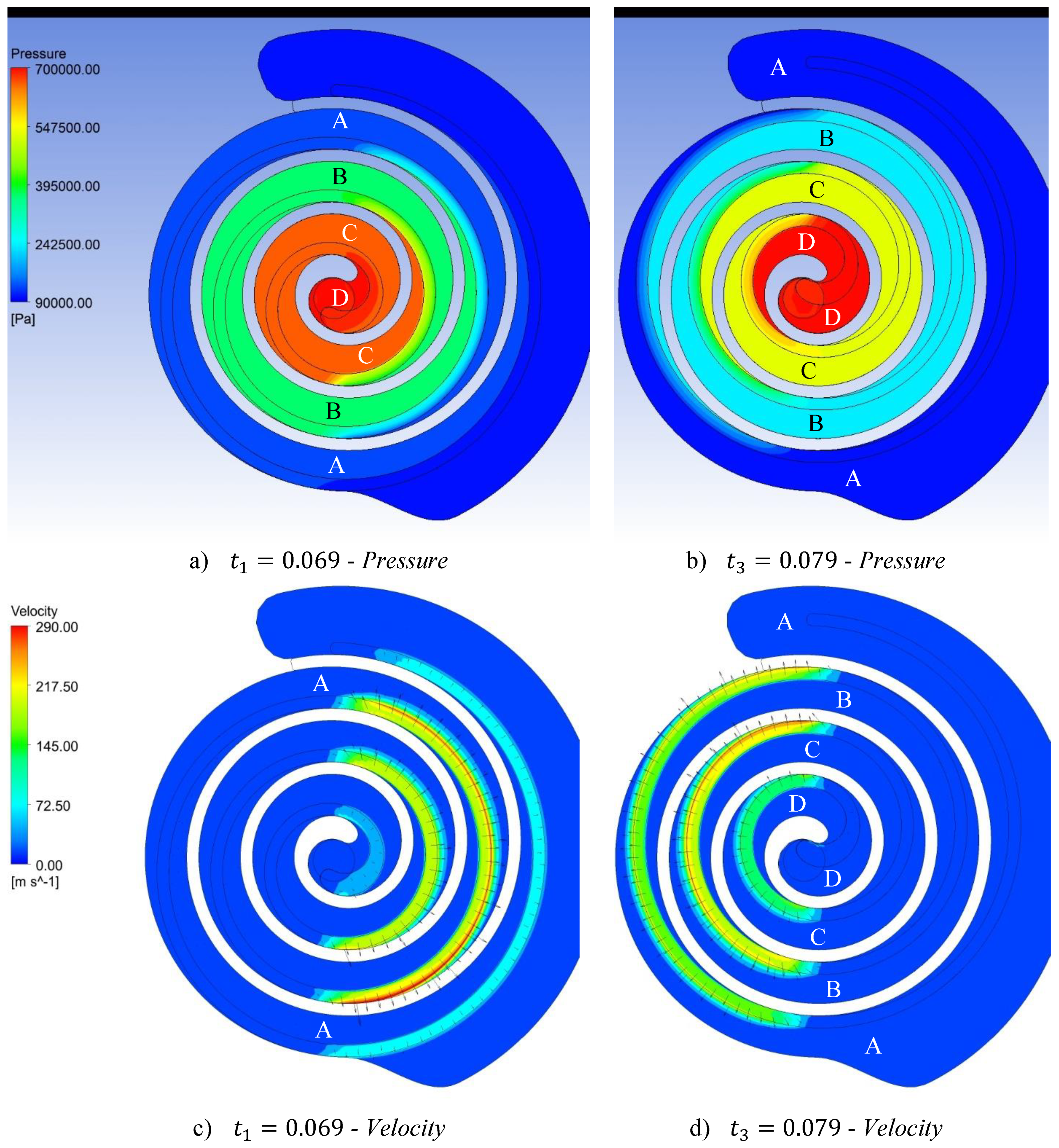
There is a clear cause-and-effect relationship between the three trends. At the instant t
1, the discharge process of the mass flow rate is in its final phase (dash-dot line in
Figure 19). The pockets D, already merged, are discharging the residual compressed air at a constant rate and the air pressure in the subsequent pockets C is close to the maximum value (
Figure 20a). Therefore, the pressure difference between pockets D and C is small, resulting in a poor radial leakage flow in the axial gap between those pockets (
Figure 20c). Similar situation characterizes the pockets A, which have just started the compression process: Their pressure is almost equal to that of the suction pocket and the leakage flow is minimum (
Figure 20a,c). At this instant, the pressure at the inlet port is lower than that of the environment and the gradient pressure favors the entrance of new air mass, as demonstrated by the maximum value of the inlet mass flow rate (
Figure 19).
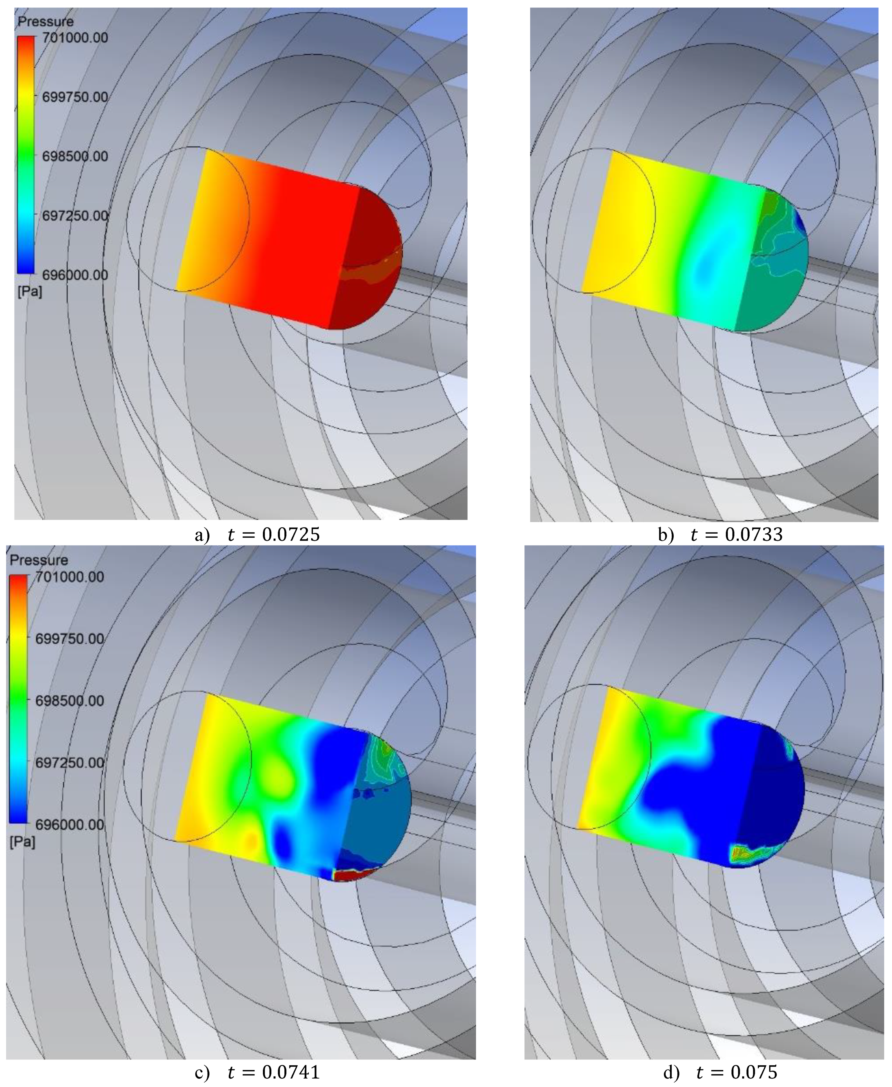
In the subsequent instants, the pressure distribution in the scroll pockets changes due to the scroll orbiting movement. At the instant
t3, the scroll is still in the middle of the discharging phase and the pockets are characterized by increasing pressure value (
Figure 20b). The pressure gradients between the pockets are not negligible and favor an intense radial leakage flow from the discharge pockets D up to the suction pocket A (
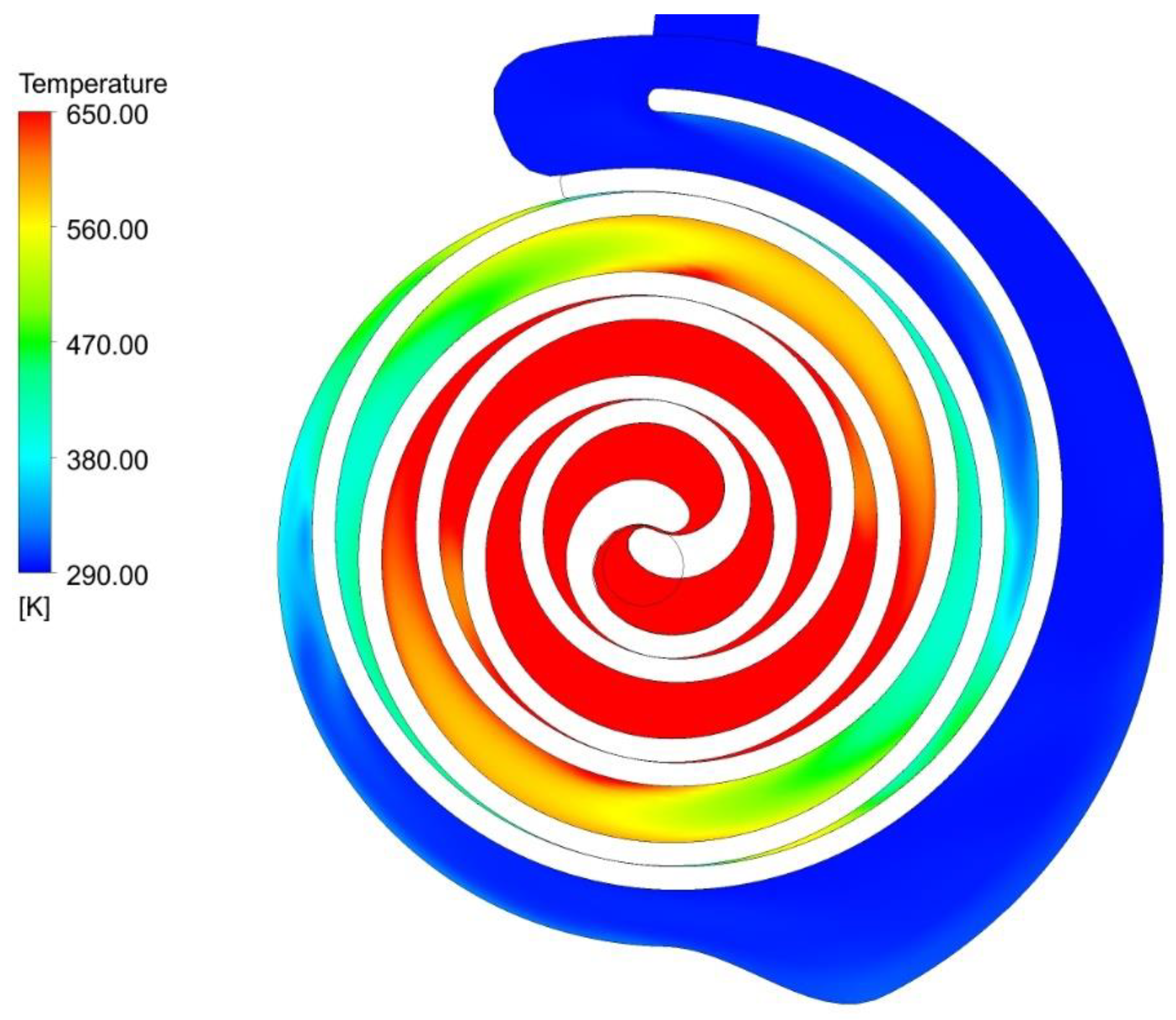
Figure 20d). This radial leakage flow brings part of its temperature and pressure content into the low-pressure pocket, causing a small increase of the pocket pressure and temperature (
Figure 21). This is clearly demonstrated by the evolution over time of the inlet pressure in
Figure 19. Indeed, at
t3, the inlet pressure reaches the environmental pressure value, 1 bar, and this prevents to the air mass to enter into the suction pocket, bringing the mass flow rate to null or even negative values (
Figure 19).
It must be pointed out that the axial gap not only affects the inner fluid dynamics within the scroll pockets, but also in the discharge duct. The mass flow jets coming out from discharging pockets, clearly captured in the analysis without the axial gap (
Figure 11), are significantly damped down in the simulation with the axial gap (
Figure 22) mainly for two reasons. First, the mass flow rate discharged by the scroll is smaller due to the increased mass leakage flowing back to the entrance. Then, the axial gap makes a mass flow exchange possible between the discharging pockets due to the onset of pressure gradients (see contour plot over the orbiting scroll width in t
5 and
t7 –
Figure 22). Consequently, the mass flow rate at the outlet port is more uniformly distributed over time and the amplitude of the peak at the beginning of the discharging phase is significantly reduced (
Figure 23).
Besides the average mass flow rate reduction, it is important to highlight that, in terms of scroll global performance, the pressurizing effect of the radial leakage linked to the axial gap significantly increases the scroll power consumption: 3.6 kW vs. 2.8 kW.
Figure 23 also highlights that the modelling approach based on a perfect tip seal prevents PumpLinx from capturing significant differences with the simulation without axial gap. The small reduction in the average mass flow rate caused by the increased tangential leakage flow is confirmed. This reflects in the global performance, whose values are slightly increased in comparison with the previous case. For example, the average power consumption just increases from 2.7 kW to 2.9 kW.
5. Conclusions
Even if scroll machines present a wide application range, their efficiency is often one of the main bottlenecks for increasing the performance of the overall system/technology in which they are applied. Unlike turbomachines, the design strategy of these machines (and more in general of positive displacement machines) is limited to theoretical and/or semi-empirical approaches. A fact linked to the complex fluid dynamics combined with challenges in applying CFD software.
This paper analyses the inner fluid dynamics of a scroll machine with a particular focus on the influence of the axial gap on the resulting performance. Indeed, axial gap is one of the most challenging aspect to consider in a CFD simulation and its relevance in scroll design are clearly demonstrated by experimental studies.
To discriminate between different factors affecting the scroll flow field, CFD simulations are carried out with and without the axial gap. This approach makes it possible: (i) To study the fluid evolution within the scroll wraps and the unsteady phenomena caused by the porting process and (ii) to analyze the influence of the axial clearance on the main fluid flow.
Moreover, since innovative design strategies are generally based on CFD fluid-dynamic analyses, a comparison between numerical models is carried out to highlight strengths and weaknesses of the available approaches.
Regarding the scroll machine fluid flow field analysis, it can be concluded that:
A tumble motion arises in the inlet pocket from the interaction between the mass flow rate entering in the suction pocket and the outside surface of the orbiting scroll. The location of the inlet port affects the onset of this tumble motion and, hence, it shall be considered during the scroll design.
The discharge process at the scroll outlet is perturbed by jets of mass flow and unsteady inertia phenomena, whose influence is propagated up to the scroll inlet, causing the pulsation of the inlet mass flow rate. To affect these phenomena and the consequences on the inlet mass flow rate, possible modification of the discharge port geometry needs to be considered during the scroll design. The relevance of the discharge port shape on the scroll performance is also deduced in the analysis of Cavazzini et al. [
29], but in their study, the root causes have not been identified.
The axial clearance increases the tangential leakage of the radial clearance and determines the onset of a radial leakage flow, whose intensity depends on the pressure gradient between pockets. When this radial leakage is not negligible, it is able to slightly pressurize the low-pressure pockets, increasing the counter-pressure and, hence, the scroll power consumption. Moreover, the pressurization of the inlet pockets is the cause of the null or reverse mass flow rate at the inlet port. This affects the average mass flow rate and power consumption, and hence, need to be considered during the design phase.
As regards the CFD models, the comparison brings to the following conclusions:
The scroll fluid dynamics is characterized by unsteady separation zones mainly related to the charge (e.g., tumble motion) and discharge (e.g., mass flow jets) process, and the k-ε model, because of its characteristics, is not as accurate as other turbulent models (e.g., SST) in reproducing them. Nevertheless, its robustness and timesaving make it suitable for comparisons between different design solutions within an optimization procedure, which is a time-consuming process generally requiring hundreds, even not thousands, of simulations.
The modelling strategy based on a perfect tip seal does not reproduce accurately the influence of the axial gap on the fluid dynamics and performance of a scroll machine. Even if the pressure gradient between the pockets pushes the tip seal against the stator wall, experimental studies demonstrate that a perfect sealing can be never achieved, even in the case of high-pressure ratio, and that the radial leakage flow, which is not considered in a perfect-tip-seal modelling strategy, is a matter of fact.
The strategy based on modelling the axial gap is closer to the real operating conditions since it allows to consider the radial leakage through pockets. However, the axial clearance in this modelling strategy is assumed to be constant which is not fully consistent with the real operating condition. Indeed, the leakage flow rate is governed by a tip clearance that depends on the pressure forces acting on the tip seal, varying during the scroll revolution as a function on time. The relevance of this time-dependent behavior of the tip seal in terms of simulation accuracy is not fully negligible since the flow in the axial gap can easily reach transonic velocities with the consequent chocking of the axial gap. So, if the simulation goal is to analyze new design solutions of the tip seal for damping down mass flow rate pulsations and/or to simulate as much accurately as possible the scroll performance, it is necessary to consider this time-dependent behavior, with the consequent need for the development of a new and more complex modelling strategy.


