1. Introduction
Internet of things devices and smart sensors have been installed on transmission towers to monitor their operation in real-time, such as tower structure, transmission line, cable galloping, wire temperature, wind speed, cable current, voltage phase angle, and power [
1,
2,
3,
4]. A high voltage of transmission tower is not used for these multiple low power online monitoring devices. Hence, a separated isolated power supply is needed to power these devices. Wireless power transfer technology is a viable option to supply power to these multiple online monitoring devices.
The power transfer distance depends on coil dimensions because the magnetic coupling decreases as the distance increases [
5,
6]. To transfer the power efficiently over a long distance, repeater coils are used [
7,
8,
9]. In [
10], a relay resonator is used for higher transmission efficiency and stability of the WPT system. In the case of coupling coefficient variation in time between transmitter (
TX) and receiver (
RX) coils, repeater coils can be used to mitigate the power losses [
11]. It has been studied that cross-coupling effects of nonadjacent resonators would cause the maximum efficiency operation to slightly shift away from the resonance frequency of the resonators [
12]. A repeater coil has been used to avoid power transfer efficiency degradation due to the Rx coil surrounding environment and process variations in implantable biomedical applications [
13]. An optimization method for a WPT system with the use of a repeater was proposed to increase both PTE and power transferred and presented a tuning technique for the performance improvement against load variations in Reference [
14]. Power transfer efficiency analysis was carried out for an intermediate resonator with a load connected and without the load connected, and higher PTE was obtained with an intermediate resonator with the load connected than the relay (without load) [
15]. In [
16], a repeater coil was used to transform the reflected load at the Tx.
However, in these papers, the load is connected to the last coil, and the load is not attached to repeaters except in Reference [
15]. There are some applications where multiple loads need to be powered [
5]. For example, accurate data can be obtained for power system analysis, early warning, and disaster prevention using IoT technology [
17]. As mentioned earlier, different smart sensors and smart meters have been installed on transmission towers to monitor the operation in real-time [
1,
18]. We can supply power to these multiple IoT devices installed in series on transmission towers using WPT technology with intermediate resonators. Moreover, an isolated power supply is needed for gate drivers of IGBTs used in converters in the flexible AC transmission system (FACTS). Thus, the WPT technology provides an ideal solution for multiple isolated power supplies [
19]. These multiple driver circuits act as multiple loads for the WPT system [
20]. Therefore, the WPT system transferring power to multiple loads with equal power distribution as for IGBT driver circuits and different power distribution as for different IoT devices needs to be studied.
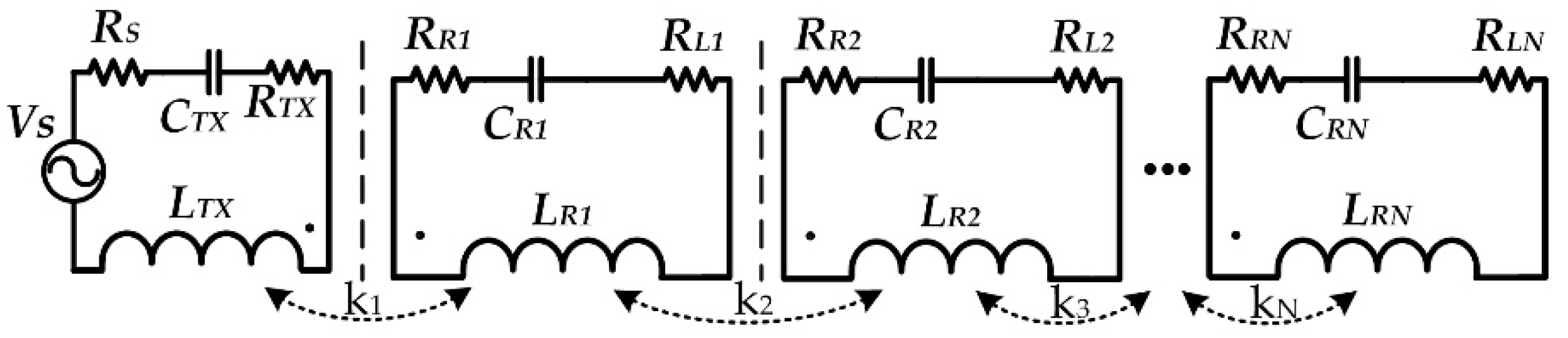
Figure 1 shows a WPT system transferring power to multiple loads with equal power distribution, where the different optimized load is connected to all the repeater coils [
19]. However, if anyone of the loads’ changes, efficiency decreases. Moreover, an additional dc-dc converter is needed at each repeater to adjust the load variation, which increases power losses and the number of components. Similarly, a WPT system with multiple loads was proposed in Reference [
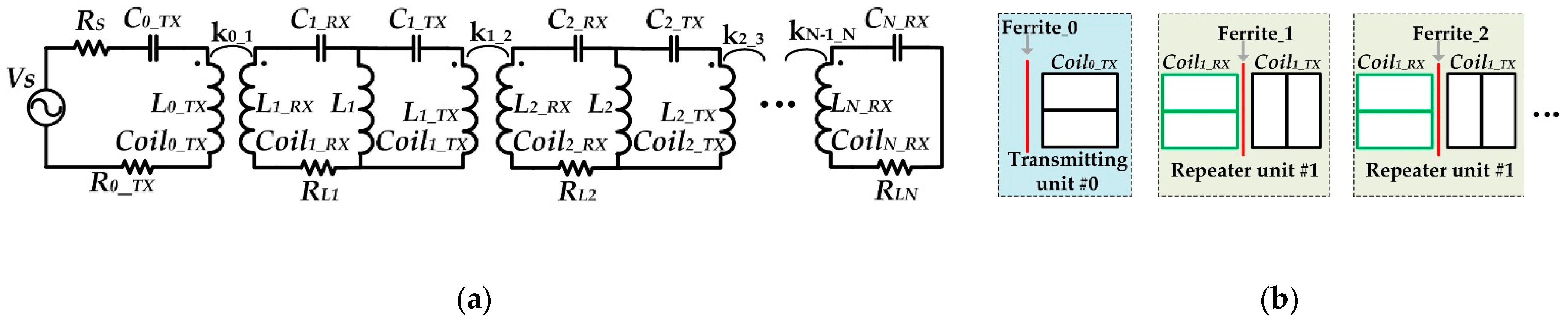
21]. However, the load power changes at each load with the change of one of the load resistances. Thus, in practical applications, it requires a complex control method. In [
5], a WPT system with load-independent characteristics, transferring power to multiple loads was proposed. However, two coils and an inductor were used at each receiver, and ferrites plates were inserted between the two coils in the same repeater. Moreover, the transmitting and receiving coil increases the system size and makes it bulky as shown in
Figure 2.
In this paper, a novel load-independent WPT repeater system with multiple loads, having equal power distribution and load-independent characteristics with high efficiency, is proposed. Previously reported WPT repeater systems with multiple loads have either used optimized different loads at each repeater to obtain equal power distribution, where any optimized load value changed at any repeater affects the load power of all other repeaters [
19,
21]. Otherwise, it needs to use an extra inductor and two coils at each repeater to achieve the equal power distribution with load-independent characteristics at the expense of system size [
5]. The proposed system achieved load-independent characteristics and equal power distribution with a single coil and without the use of an extra inductor at the repeater and load variations at any repeater, which did not affect the load power at the other repeaters. Moreover, previously reported WPT repeater systems with multiple loads have not implemented the rectification and power regulation, while the proposed system achieved the rectification and power regulation by implementing the self-regulated rectifier. The efficiency of the proposed system is not degraded if any of the load value is changed from its nominal value during system operations.
2. Description of the Proposed Multi-Load WPT Repeater System
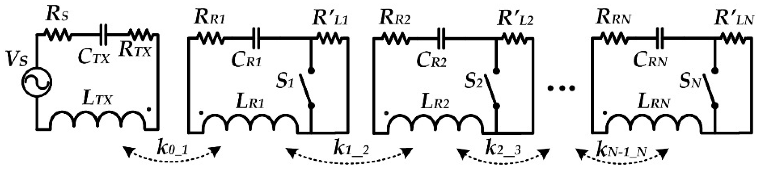
Figure 3 shows the circuit topology of the proposed multi-load WPT repeater system with a
TX coil (
LTX) and the
N-number of power relays (
LRi,
i = 1,2,…,
N). Where
R’Li and
RRi (
i = 1,2,…,
N) are the equivalent AC load and parasitic resistances of the repeater coils, respectively.
RTX is the transmitter parasitic resistance and source resistance is represented by
Rs resistor. Two MOSFETs are used in a full-wave rectifier instead of diodes for each repeater, to realize the switches (
Si, i = 1,2,…,
N).
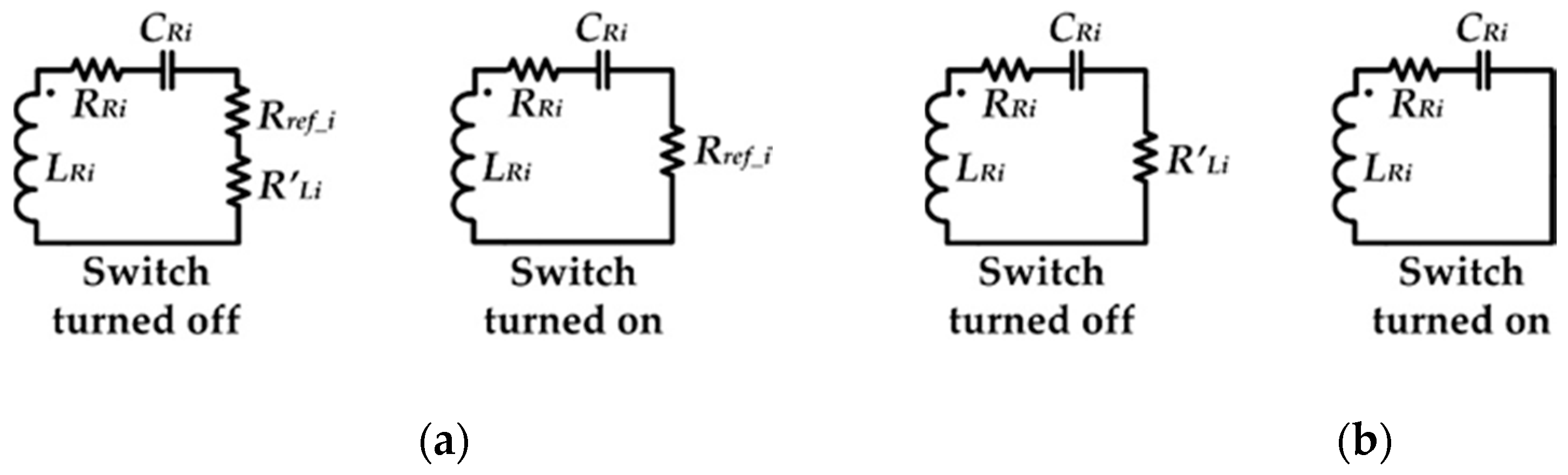
When the switches of a repeater are turned on, the repeater functioned as a power relay, and power was not delivered to the local load. Power was delivered to the connected load of a repeater when the switches are turned off. Switch turned off and on, the equivalent circuit of a repeater with its equivalent ac load (
R’Li) and the reflected load (
Rrefl_i) (
i = 1,2,…
N) from the adjacent repeater is shown in
Figure 4a.
Figure 4b is the switch turned off and on, the equivalent circuit of the last
Nth receiver.
2.1. Circuit Structure
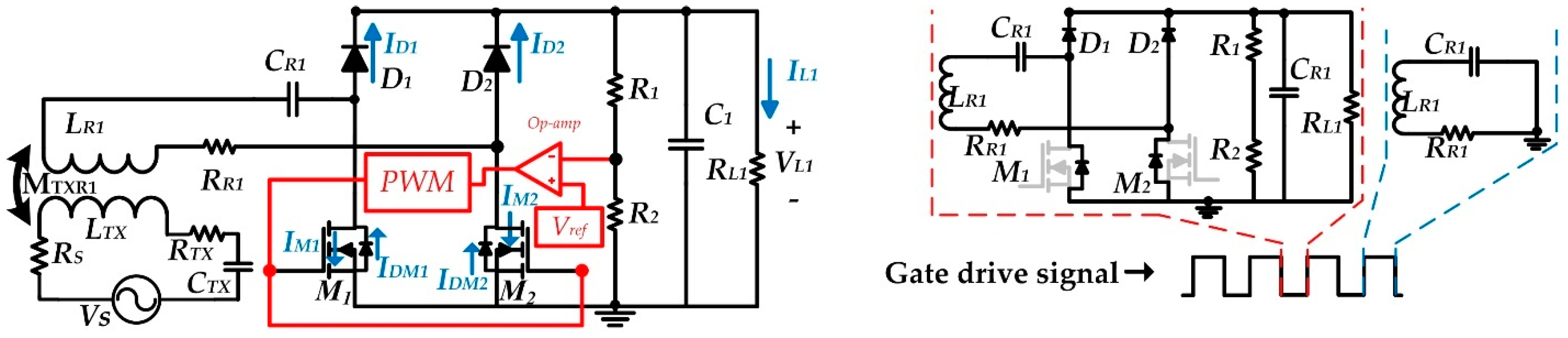
Figure 5 shows the
TX and structure of a repeater of the proposed multi-Load WPT repeater system. The circuit structure and working principle of all other numbers of repeaters and the last
Nth receiver are the same. Therefore, only one repeater is shown, and its working principle is explained. A power amplifier (PA) at the
TX is modeled by a voltage source with its source resistance of
RS.
LTX and the capacitor
CTX constitute the series resonant tank with the parasitic resistance of
RTX. At the repeater side, the coil
LR1 and the capacitor
CRX formed a series resonant tank. The full-bridge rectifier consists of two diodes,
D1,
D2, and two MOSFETs,
M1,
M2, to provide DC voltage to the load
RL1. In this implementation, two NMOSs are used instead of two rectifying diodes of the conventional full-wave rectifier.
M1 and
M2 are not only used for rectification but also regulate the output power of the repeater. When
M1 and
M2 are turned off, power is delivered to the load
RL1 and current is passed through the body diodes of
M1 and
M2. Power is not delivered to the load
RL1, upon turning on of
M1 and
M2 and the repeater worked as a power relay to deliver power to the adjacent repeater.
2.2. Power Regulation
In the proposed multiple loads WPT relay system, output voltage regulation is achieved at each repeater and the last receiver, using a self-regulated rectifier as proposed in References [
22,
23]. In [
22], the threshold voltage of the MOSFETs was used for voltage regulations and tight regulation was hard due to the variation of the threshold voltage of the MOSFETs. The self-regulated rectifier of Reference [
23] was proposed for a parallel resonant receiver to modulate the load resistance seen at the input of the rectifier. However, in the proposed multiple loads WPT relay system, to achieve tight regulation, to solve the issue of threshold voltage variations of the MOSFETs, and applicable for the series resonance of the WPT relay systems, we generated the
PWM using voltage reference and feedback voltage.
Initially, the output capacitors of all the repeaters and the last
Nth receiver are not fully charged; therefore, the switches are turned off. First, the capacitor of the first repeater is charged to the targeted voltage, and then the switch of the first repeater is turned on. Then, the capacitor of the second repeater is charged to the targeted voltage, followed by the third repeater capacitor, so on, up to the last receiver.
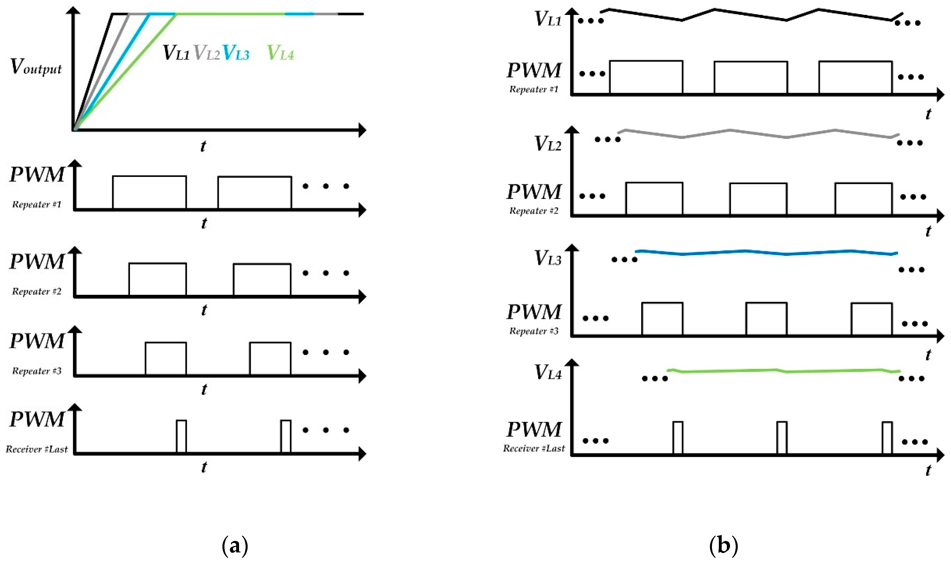
Figure 6 shows output voltages and
PWM signals of the MOSFETs gates for four multiple loads WPT system, that is, three repeaters, and the fourth one is the receiver.
As shown, conceptual waveforms in
Figure 6a, the output voltage
VL1 of the repeater #1 reaches the targeted voltage first and its switches are turned on, then repeater #2’s switches are turned on when output voltage
VL2 reaches the targeted voltage followed by repeater #3 and the last receiver switches are turned on upon output voltages,
VL3 and
VL4, reaching their targeted voltages.
Power regulation is achieved by turning on and off, the switches of the repeaters as shown in
Figure 6b. MOSFETs of the repeaters are turned on when the target voltages of the repeaters are obtained, and output capacitors are starting to discharge. Upon decrease of voltages from the targeted voltage, the MOSFETs are turned off and the power is delivered to the load to charge the capacitor to the targeted voltage. The repeater with the large turned on duty ratio has a high output voltage repels compared to the repeater which has a small duty ratio. As shown in
Figure 6b, repeater #1 is nearest to the transmitter that has a large duty ratio; therefore, it has a high voltage repel. However, the last receiver which is farthest away from the transmitter has a small duty ratio and has small output voltage repels. High output voltage repels can be suppressed by using a high capacitance value capacitor if there is no size limitation.
3. System Analysis and Coil Design
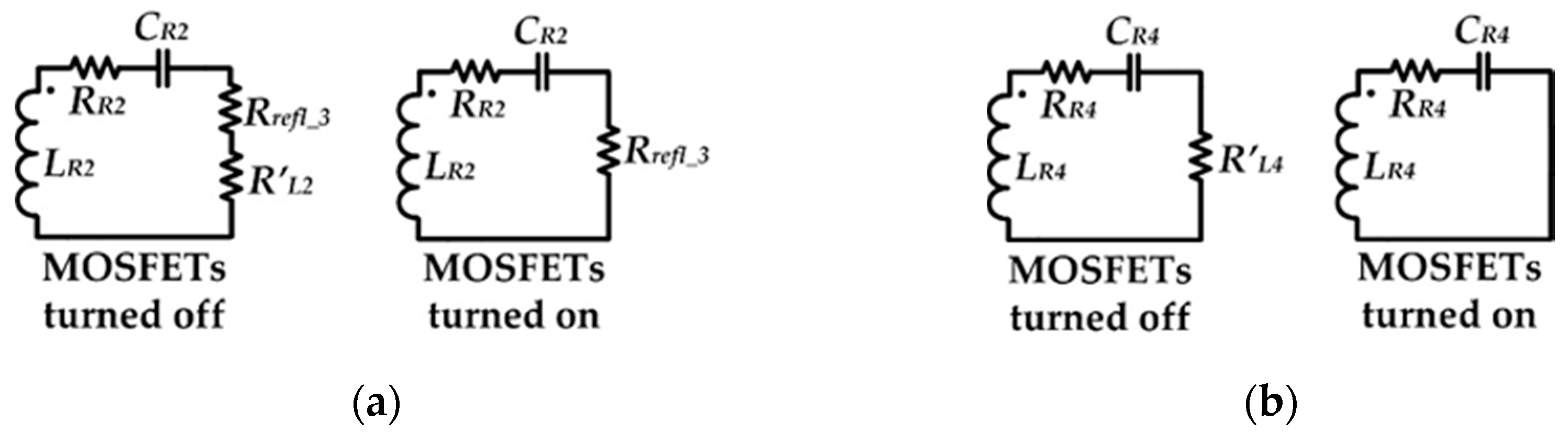
The reflected load at each repeater during system operation depends on the operating condition of the other repeater adjacent to it. For example, reflected impedance at repeater #1 depends on the operating condition (MOSFETs turned on or off) of repeater # 2. When the repeater #2 MOSFET’s are turned off or on, then the equivalent circuit of repeater # 2 is shown in
Figure 7a, where
Rrefl_3 is the reflected impedance from the repeater #3 to repeater #2 and
RL2 is the equivalent AC load of the repeater #2. Therefore, depending on these two cases, the reflected impedance at repeater # 1 can be calculated as follows.
Case 1: When repeater #2 MOSFETs are turned off, then reflected impedance at repeater #1, assuming full resonance at the resonance frequency
fo, can be calculated by Equation (1):
Case 2: When repeater #2 MOSFETs are turned on, then reflected impedance at repeater #1, can be calculated as:
From Equations (1) and (2), the reflected impedance
Rrefl_2 at the repeater #1 is larger when the switch (MOSFETs) of the repeater #2 is turned on as compare to turned off because the AC load
RL2 of the repeater 2 is omitted for the turned-on case. Similarly, reflected impedance
Rrefl_1 at the transmitter can be calculated as
when the switch of repeater #1 is turned off. The reflected impedance
Rrefl_1 at the
TX side, for the repeater #1 switch turned off case is given by
Figure 7b shows the equivalent circuit for the last receiver. The reflected impedance
Rrefl_3 seen by repeater #3 from the last receiver is given by Equation (5)
When the receiver switch is turned off. The reflected impedance
Rrefl_3, when the receiver is turned on is given by
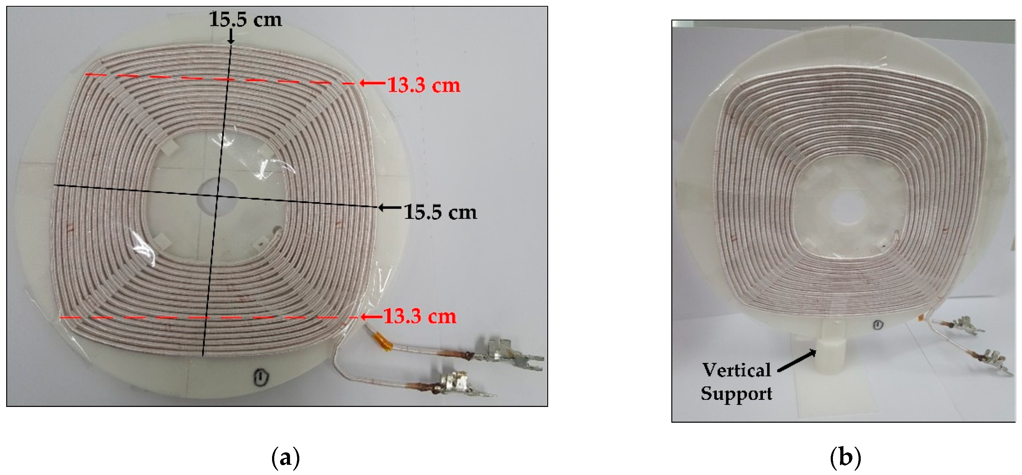
To reduce power losses at each repeater, high-quality factor coiled is required with small parasitic resistance. In the proposed multi-load WPT relay system, five identical coils were designed, one coil for TX and four coils for three repeaters, and the last receiver. High-quality factor coils were designed using 1000-strand Litz wire having a wire diameter of 3 mm so that the skin effect can be neglected. Each coil had a quality factor of approximately 427 with an inductance of about 34 μH with the measured coil parasitic resistance of approximately 0.5 Ω. The Pitch of the coil was about 0.4 mm.
Figure 8 shows the shape of the designed coil.
4. Experimental Results
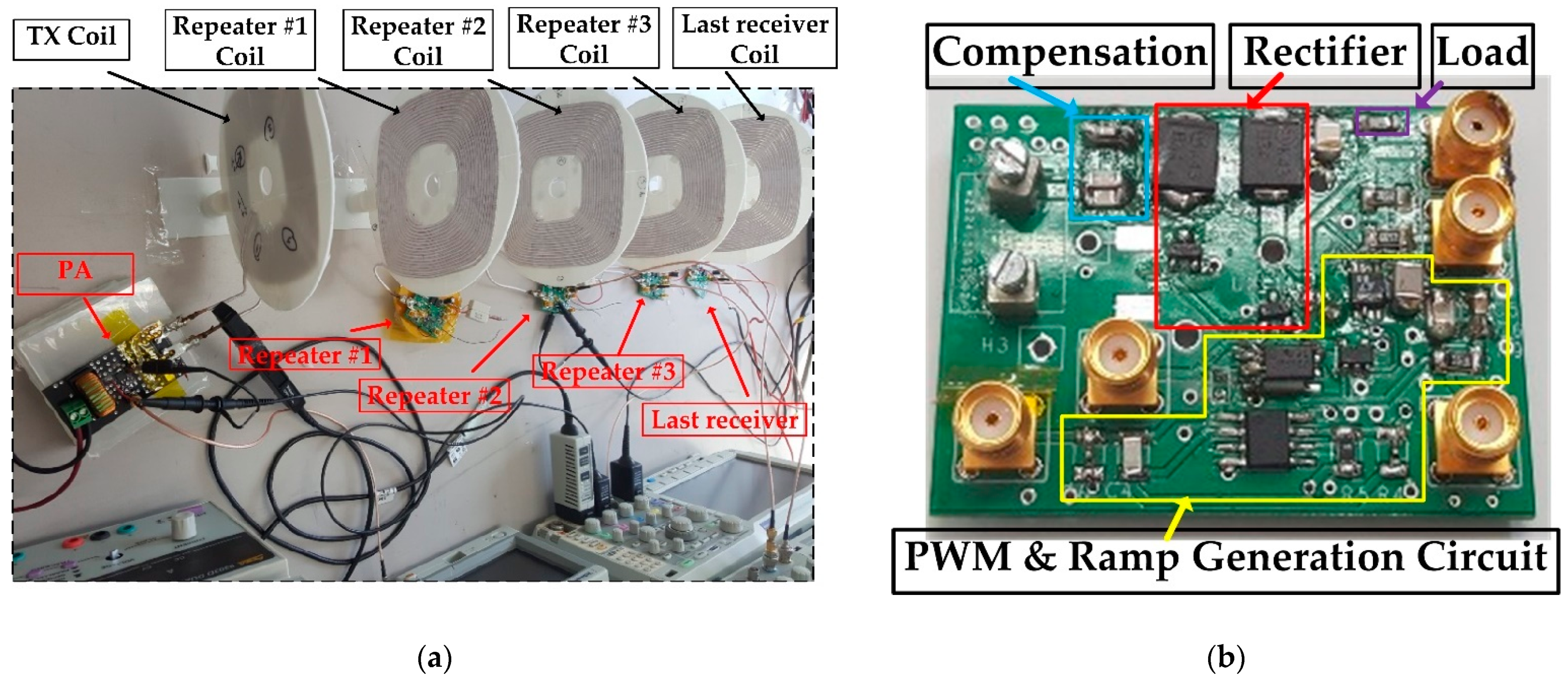
Figure 9 shows the experimental setup for the proposed multi-load WPT relay system, having five units, that is, one transmitter unit, 3 repeater units, and a fifth one receiver unit. The power delivered to every four loads was 2.27 W, which is enough for IoT devices and the output voltage was 5 V. The load value used was 11 Ω. The total efficiency of 51.7% was achieved with a total distance of 62 cm, having a 15.5 cm distance between every two coils.
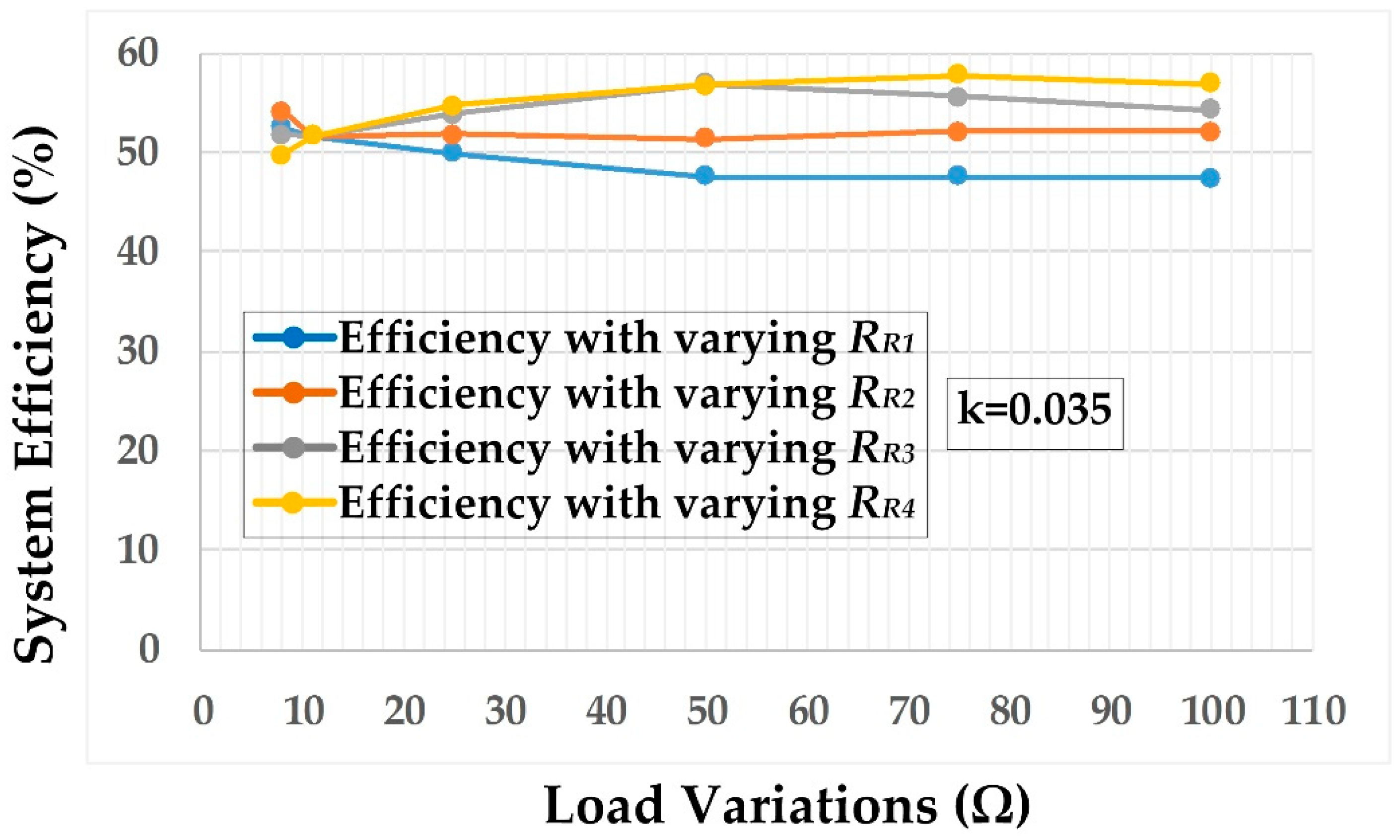
The change of any one of the loads from its load value of 11 Ω does not affect the power delivered to the other loads and the overall system efficiency was even increased for the load variation at repeater #3 or the last receiver as shown in
Figure 10. For repeater #1, the increase of load resistance from its nominal value of 11 Ω, one at a time (for example,
RR1 is changed while all other loads are constant) showed a small decrease of efficiency at large load resistance. For repeater #2, the increase of load resistance from its nominal value did not have a significant change of efficiency and a small increase of efficiency if the load value was decreased from the nominal value. The load variation at repeater #3 or the last receiver had a significant increase in efficiency when the load value was increased but for the last receiver, if the load value was decreased from its value of 11 Ω, then the overall system efficiency dropped to 49.8% at 8 Ω.
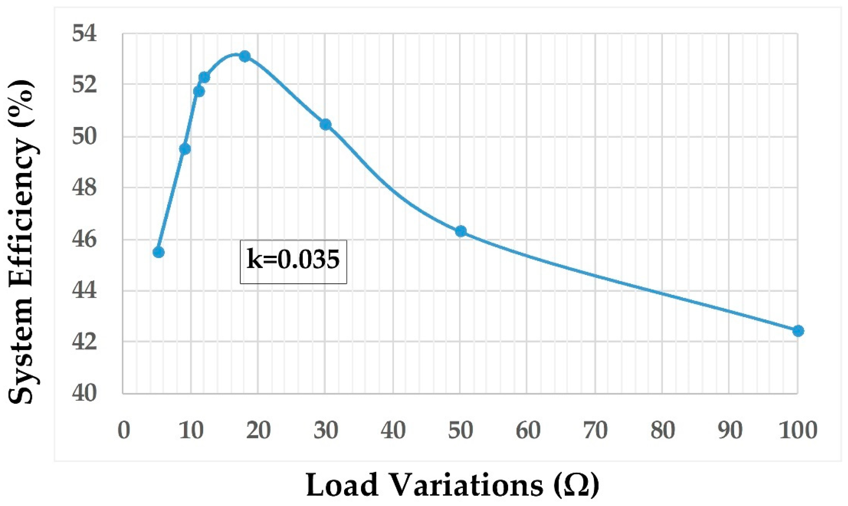
Figure 11 shows the overall system efficiency when all four loads are varied. It shows the high system efficiency at the load value of 18 Ω for all the four loads. When all the four load values are smaller than the 9 Ω then the system efficiency is decreased because the reflected load at any of the repeater is becoming larger than the AC load of the repeater, which is in series with the reflected load. In that case, the power loss at the adjacent repeater is increased significantly. For example, for a load value of 8 Ω, assuming full resonance, the reflected load from receiver to repeater #3 is 46.9 Ω, while the AC load of repeater #3 is 6.48 Ω. Therefore, most of the power is consumed at the reflected load of 46.9 Ω and the receiver targeted voltage of 5 V is obtained before the repeater #3 target voltage of 5 V. Power loss at the receiver was large to get the targeted voltage of 5 V at repeater #3, as the receiver started regulation of voltage before the output voltage of repeater #3 reached its targeted voltage. At large load resistances, the system efficiency decreased because the high power losses occurred during the switch-on time at the repeaters when the reflected impedance was small at the repeaters.
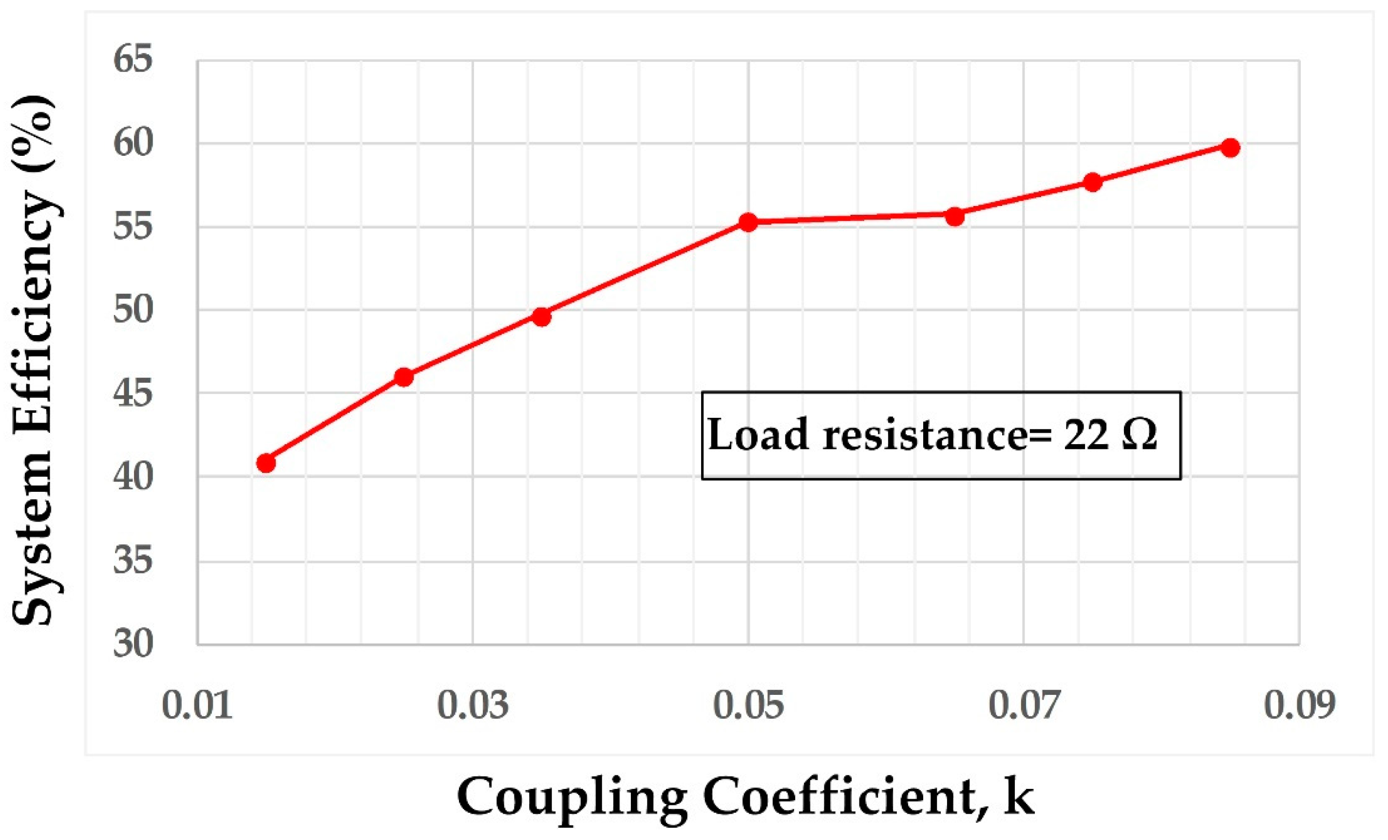
System efficiency against coupling coefficient (k) variation is shown in
Figure 12 for a load resistance of 22 Ω for each load. For k 0.015 to 0.05, the change of frequency was large, but from 0.05 onwards the increase of efficiency was small. Though the reflected impedance at the transmitter increased with the increase of the k and efficiency of the system was increased, at the high coupling coefficient values, the reflected impedance at the repeaters also increased. When the reflected impedance at any reflector becomes equal or greater to the AC load of the repeater then the efficiency increased is small even with a high coupling coefficient value, as in the case of an increased coupling coefficient beyond 0.05.
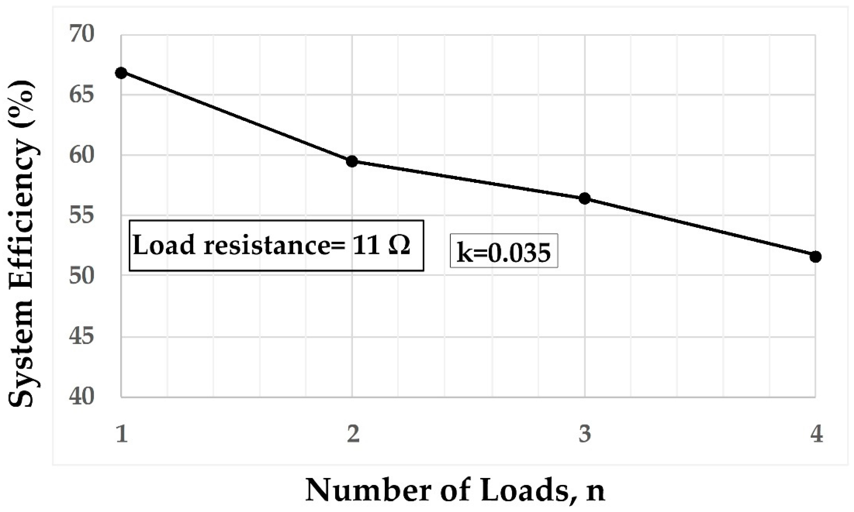
There is a trade-off between the number of loads and the system efficiency as shown in
Figure 13. System efficiency is decreased with the increased number of loads. With a single load (n = 1), which is the conventional two-coil (
TX and
RX) WPT system, the maximum efficiency was achieved of 67%. When n = 4 (three repeaters and last receiver), the efficiency of the multi-load WPT relay system was 51.7 %. However, the number of loads can be increased with high system efficiency by increasing the coil quality factor and k.
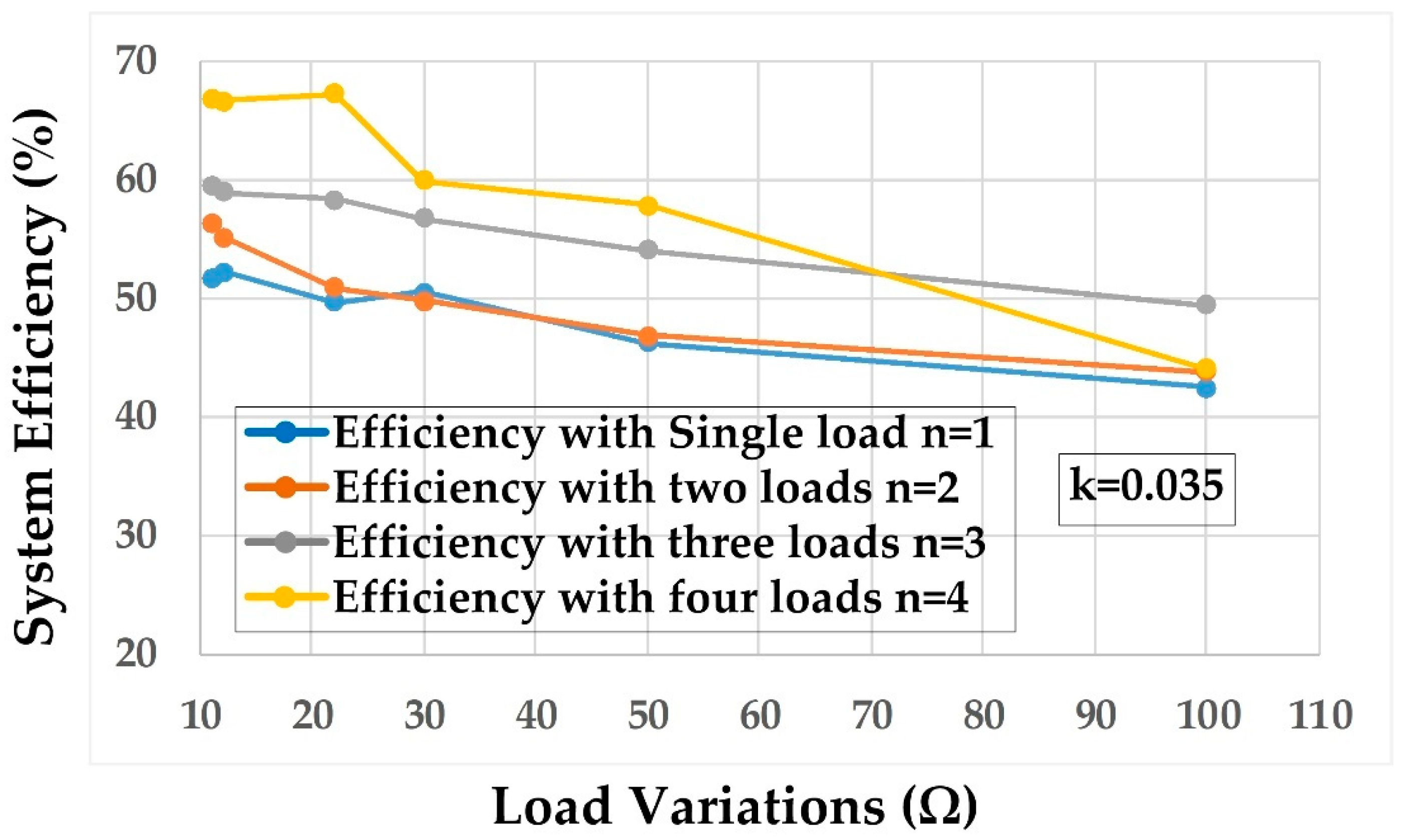
Figure 14 shows the number of loads n and its total efficiency against load resistance variations. When the load resistance value is small, the system efficiency for single load n = 1 is large and decreases with the increased number of loads. For load resistance variations, the system efficiency change is large for n = 1 compared to multiple loads (n > 1).
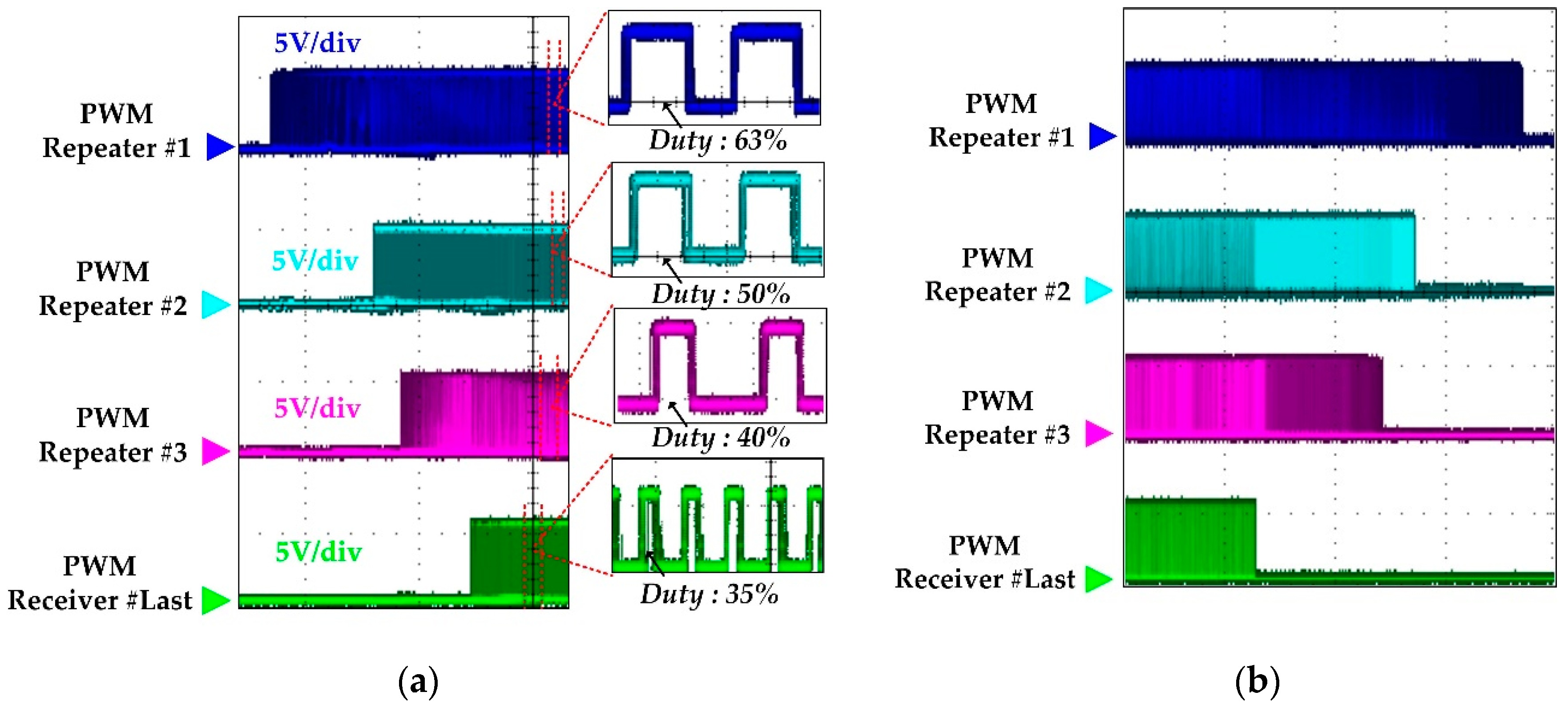
The switches turned on sequence, as explained in
Section 2.2, and switches turned off sequence, is shown in
Figure 15. When the input power of the
TX is reduced, then the target voltage of the last receiver is decreased first and its switches are turned off first, then the third repeater targeted output voltage of 5 V is decreased, and its switches are turned off second. The second repeater switches are turned off third, and at the last first repeater, the switches are turned off.
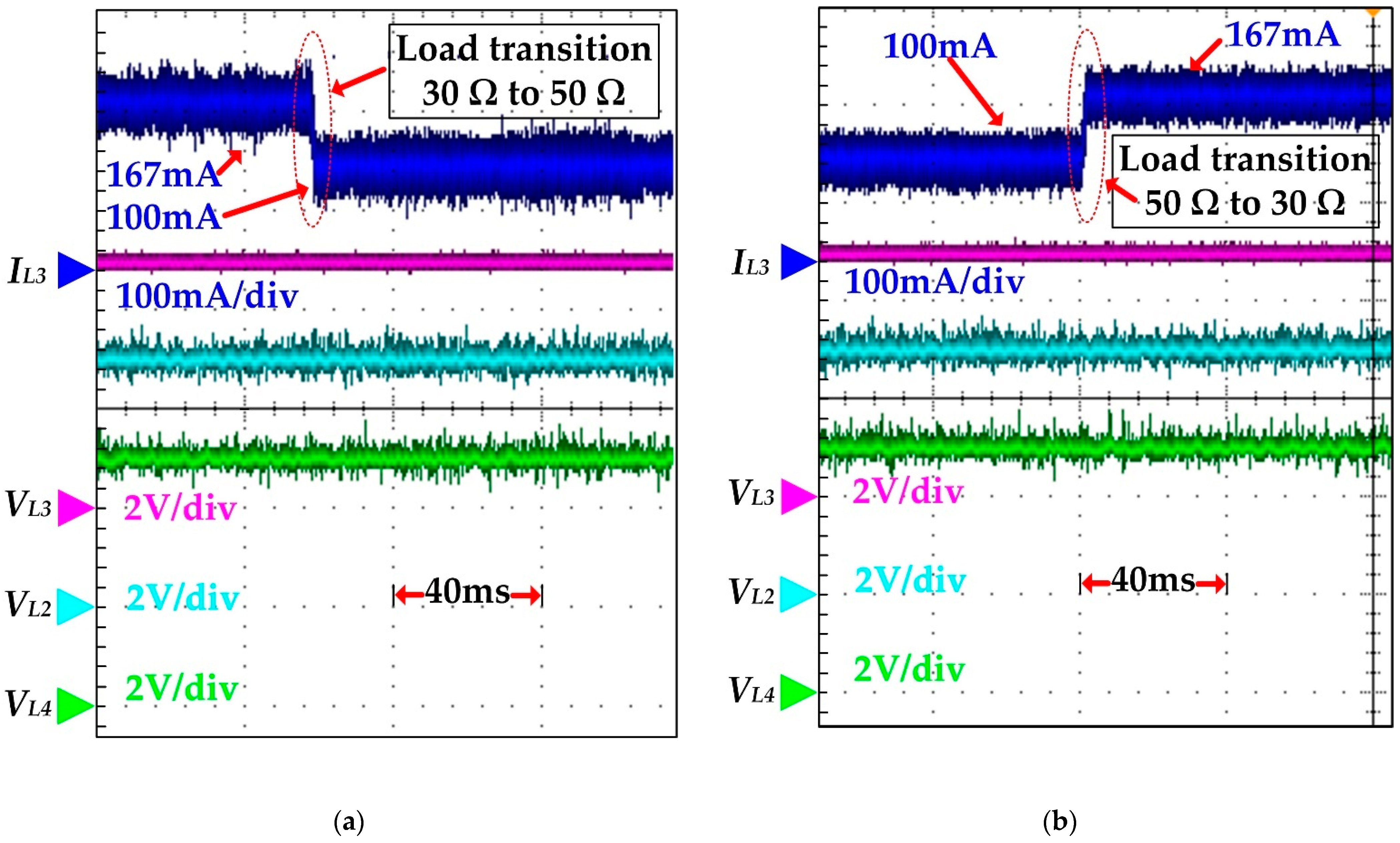
Load resistance
RL3 of repeater #3 was changed while load resistance of the first and second repeater and the last receiver were kept the same and constant. When the load resistance
RL3 is changed from 30 Ω to 50 Ω and vice versa, the power regulation is achieved well, as shown by the load transient waveforms of
Figure 16. Output voltage
VL1 of the first repeater is not shown due to the limitation of oscilloscope channels. When the
RL3 is changed from 30 Ω to 50 Ω the output current is decreased to regulate the output voltage
VL3 of the third repeater. The load transition at the third repeater does not have any effect on the voltage or output power of the first and second repeaters, and the last receiver.
5. Comparison of the Proposed Multi-Load WPT Relay System with the Previously Reported Systems
In [
18,
24], the energy is harvested from the magnetic field around the transmission line and it wirelessly transfers the power using resonators embedded inside sealed insulation discs while delivering power to only a single load. Meanwhile, the proposed WPT repeater system delivered power to multiple loads. Some readers may think why not use wires to power these IoT devices using a step-down transformer. As transmission line voltage is very high; therefore, a very large size transformer is needed to step down high voltage to the required low voltage, which is costly. The installation of the large size transformer on the transmission tower with isolation is difficult. Moreover, using the number of wires to power multiple loads may cause isolation issues with transmission lines. The proposed WPT repeater system delivered isolated power to multiple loads without any issues as mentioned for delivered powered with wires.
Table 1 shows the summary of the proposed multi-load WPT relay system compared to other previously reported multiple load WPT relay systems in the literature.
The key components used for all the three repeaters and the last receiver are the same; therefore,
Table 2 shows the names of parameter references to the first repeater, as shown in
Figure 10.
The total component cost to delivered power to a single load is approximately
$28 (
TX and repeater components) and is increased with the number of loads to deliver power. For example, to deliver power to two loads, the total component cost is approximately
$45. The cost is not too high with the proposed solution compared to delivering power separately to each IoT device by using a battery, DC/DC converter, and voltage regulator (LDO). The cost of the DC/DC converter and LDO is approximately
$15 to deliver power to a single IoT device.
Table 3 shows the components cost of the
TX and a repeater.


