Abstract
Miscible and near-miscible flooding are used to improve the performance of carbon-dioxide-enhanced oil recovery in heterogeneous porous media. However, knowledge of the effects of heterogeneous pore structure on CO2/oil flow behavior under these two flooding conditions is insufficient. In this study, we construct pore-scale CO2/oil flooding models for various flooding methods and comparatively analyze CO2/oil flow behavior and oil recovery efficiency in heterogeneous porous media. The simulation results indicate that compared to immiscible flooding, near-miscible flooding can increase the CO2 sweep area to some extent, but it is still inefficient to displace oil in small pore throats. For miscible flooding, although CO2 still preferentially displaces oil through big throats, it may subsequently invade small pore throats. In order to substantially increase oil recovery efficiency, miscible flooding is the priority choice; however, the increase of CO2 diffusivity has little effect on oil recovery enhancement. For immiscible and near-miscible flooding, CO2 injection velocity needs to be optimized. High CO2 injection velocity can speed up the oil recovery process while maintaining equivalent oil recovery efficiency for immiscible flooding, and low CO2 injection velocity may be beneficial to further enhancing oil recovery efficiency under near-miscible conditions.
1. Introduction
Oil production plays a significant role in global economies and is also the prime focus of climate change policies [1]. Carbon-dioxide-enhanced oil recovery (CO2-EOR) is a technology that injects CO2 into oil reservoirs and utilizes its physical and chemical interactions with oil to achieve the purposes of enhancing oil recovery while implementing CO2 sequestration [2,3]. This technology balances the benefits of the environment, the economy, and society and has been widely used in petroleum upstream industries [4,5].
Understanding CO2/oil flow behavior in porous media is critical to evaluating the performance of CO2-EOR technology [6] and optimizing CO2 injection schedules [2]. By far, most of the studies about CO2/oil flow behavior were concentrated at the core scale [7,8,9]. These studies have played important roles in analyzing the multiphase seepage characteristics of oil and CO2 in reservoir rocks (e.g., oil-effective permeability reduction) [7,8] and disclosing the phase behavior of the mixture of CO2 and oil [9]. In addition, the core-scale studies have also measured fluid and rock properties, such as relative permeability curves of oil and CO2 [10], the minimum miscibility pressure, and the interfacial tension between oil and CO2 [11,12], which provide important parameters for core-scale numerical modeling of CO2/oil flow behavior [13]. Comparatively, there is relatively less work focused on pore-scale CO2/oil flow behavior. CO2-EOR involves multiple complex processes such as fluid flow, diffusive mass transfer, and phase behavior change [2]. These processes are closely coupled with heterogeneous pore structure [14,15], and the variation of CO2 and oil distribution between large and small pores greatly determines the upscaling process [16,17]. Thus, the pore-scale investigation is important and can largely improve our understanding of the effects of these coupling processes and the microscopic pore structure on CO2/oil flow behavior and macroscopic sweeping efficiency.
In this study, we employ the direct numerical simulation approach to simulate the CO2/oil flooding process in a heterogeneous porous media under immiscible, near-miscible, and miscible conditions. The complicated coupling between fluid flow, diffusive mass transfer, and pore structure is investigated. The effects of the different flooding conditions, CO2 injection velocities, and CO2 diffusion coefficients on flow behaviors and oil recovery are also discussed.
2. Methods
2.1. Pore-Scale View of CO2/Oil Flooding
CO2-EOR is mainly categorized as immiscible, near-miscible, and miscible flooding [7]. These flooding methods have been applied to various oil fields. For instance, CO2 immiscible flooding was adopted in the Liaohe oil field in China and the Heidelberg oil field in the United States; CO2 miscible flooding was used in the Weyburn Unit oil field in Canada and the Denver Unit oil field in the United States [4]. CO2 near-miscible flooding is generally used as an alternative to CO2 miscible flooding due to lower cost and easier implementation [18].
Figure 1 shows a schematic pore-scale view of CO2 flooding in oil-saturated porous media under immiscible, near-miscible, and miscible conditions. Under the immiscible condition, there is an obvious CO2–oil interfacial intension (Figure 1a) [7,16]. Under the miscible condition, CO2 and oil would mix, and in this case, the interfacial tension disappears, which results in an easy single-phase flow in porous media (Figure 1c) [19]. Near-miscible CO2 flooding has smaller interfacial tension than immiscible flooding and weaker diffusion than miscible flooding (Figure 1b) [20]. Generally, pressure is an important index for distinguishing these flooding methods. When minimum miscibility pressure is reached or exceeded, CO2/oil flooding is miscible flooding, or else it is immiscible flooding. Furthermore, according to Chen et al. [21], the lower- and upper-pressure boundaries for effective near-miscible flooding at reservoir temperatures are 0.87 and 1.07 MMP, respectively. The main differences in these three flooding methods are summarized in Table 1.
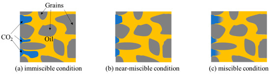
Figure 1.
Schematic illustration of pore-scale CO2/oil flooding under (a) immiscible, (b) near-miscible, and (c) miscible conditions.

Table 1.
A comparison between immiscible, near-miscible, and miscible flooding.
2.2. Pore-Scale Simulations of CO2/Oil Flooding in Heterogeneous Porous Media
- (1)
- Immiscible and near-miscible flooding models
In order to model CO2/oil flooding in porous media under immiscible and near-miscible conditions, some assumptions are needed, as follows:
- (1)
- as CO2 diffusivity in oil is small (<1 × 10⁻⁷ m2/s) [22], CO2 diffusion into oil is very slow during immiscible and near-miscible flooding and can be reasonably ignored;
- (2)
- CO2 and oil can be considered incompressible and Newtonian fluids [23];
- (3)
- the interfacial tension between CO2 and oil is almost constant [17];
- (4)
- the changes in contact angle and wettability are small and can be ignored [24]. Thus, the drainage processes of CO2-displacing oil can be defined by Navier–Stokes equations, and the corresponding conservation equations of mass and momentum are given by
The phase-field method employs thermodynamic principles to describe phase interfaces and can be used to calculate as in [25]:
where φ is the order parameter that is introduced to distinguish phases and interface; G is the chemical potential, which is defined as
where is the Ginzburg–Landau free energy; Ω represents the region of space occupied by CO2 and oil; the term accounts for interfacial energy density; F(φ) is bulk energy density, which has two minima corresponding to CO2 and oil and can be calculated by considering a Ginzburg–Landau double-well potential [25]:
where CO2 and oil take φ = −1 and φ = 1, respectively, and interface region can be described by the transition from −1 to 1; λ is the magnitude of the mixing energy, N; is a capillary width representative of the thickness of interface, m. λ and are related to the interfacial tension σ through the following equation [25]:
To make the equilibrium interface profiles between CO2 and oil satisfy and minimize the integral of ξ(φ), the convective Cahn–Hilliard equation can be expressed as a function of φ [25,26]:
where is based on Fick’s law that φ flux is proportional to the gradient of ; is the diffusion mobility, m3·s/kg.
Equations (1), (2), and (7) constitute the governing equations for CO2/oil immiscible and near-miscible flooding.
- (2)
- Miscible flooding model
Different from immiscible and near-miscible flooding, the interfacial tension between CO2 and oil disappears under the miscible condition [3,19], assuming the following:
- (1)
- CO2 can be fully mixed with oil, but the resultant oil swelling, oil extraction, and chemical reaction process can be ignored [27];
- (2)
- CO2 and oil can be considered Newtonian fluids [28];
- (3)
- the change in the diffusion coefficient is small and can be ignored [27];
- (4)
- classical Fick’s law could be valid for cases with ideal binary mixtures [29]; then, the continuity, fluid flow, and convection–diffusion equations under the miscible condition can be written as follows [30]:
- (3)
- Model domain and initial and boundary conditions
A 6330 × 4379 μm rectangle is specified as the model domain (Figure 2). The size of the domain exceeds the size of a representative elementary volume [16,31]. The domain is comprised of circular particle grains and pore spaces. Particle grains have a diameter (Dp) of 350 μm, and the pore throat diameter between them is 15 μm. Then, twenty grains are randomly selected, and their diameters are reduced or enlarged by 5% of the normal diameter, respectively, as shown in Figure 2. Consequently, all of these grains constitute a heterogeneous porous medium, with a porosity of 0.17.
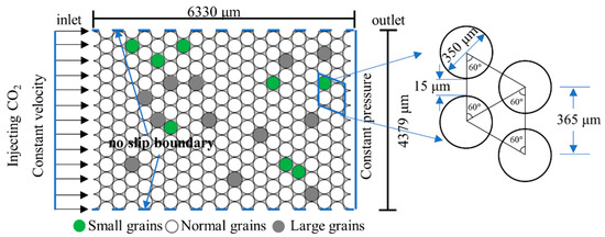
Figure 2.
Schematic diagram of the model domain and initial and boundary conditions for numerical simulations of CO2/oil flooding in heterogeneous porous media.
Initially, the model domain is saturated with oil. In the domain, the temperature is 343 K. According to Shaver et al. [11] and Georgiadis et al. [12], the minimum miscibility pressure between CO2 and oil (n-decane) at 343 K is 12.4 MPa. The initial pressure is specified as equal to 8, 11.5, and 14 MPa for immiscible, near-miscible, and miscible flooding, respectively. Then, CO2 is injected from the left boundary at a constant velocity (injection velocity uin = 0.01 m/s). During CO2 injection, the top and bottom boundaries of the model domain are specified as no-slip boundaries (u = 0). On the right boundary (i.e., the outlet boundary), the preference pressure is assumed to be zero [32], and the grain surface is also specified as a no-slip boundary. Specifically, the targeted oil reservoirs are typically oil-wet [33], and, thus, the oil-wet wall is adopted on the grain surface under immiscible and near-miscible conditions [32]:
where and is the unit normal to the wall () and the contact angle of oil, respectively, and is set to π/3.
2.3. Model Parameters
The density and viscosity of CO2 and oil, the interfacial tension, and the diffusion coefficient between CO2 and oil for immiscible, near-miscible, and miscible flooding at the specified temperatures and pressures are listed in Table 2.
Table 2.
Fluid properties for immiscible, near-miscible, and miscible flooding.
During CO2 injection, both the density and viscosity of fluids under immiscible and near-miscible conditions are functions of order parameter φ, defined as follows [23]:
The density of the fluids under the miscible condition is calculated as a linear function of CO2 concentration [35,36]:
Viscosity variation of the mixture fluids with CO2 concentration under the miscible condition can be characterized by a quarter-law mixing rule, which is written [37,38,39]
where cinj denotes the CO2 concentration in the injected solution (mol/m3); c0 is the initial concentration of CO2 in porous media (mol/m3), which is considered to be zero in our simulations.
2.4. Numerical Scheme
Numerical simulations were performed using the finite element solver COMSOL Multiphysics (COMSOL AB, Sweden). An initial time step of 1 × 10⁻⁹ s is specified, and the time step is allowed to be automatically adjusted based on the backward differentiation formula. PARDISO, which is a linear system solver in COMSOL Multiphysics, is used in this study. Mobility tuning parameter χ and interface thickness ε can influence the reality and accuracy of the numerical solutions and, accordingly, need to be carefully specified. For mobility tuning parameter χ, it must be large enough to retain a constant interfacial thickness while being small enough so that the convective terms are not overly damped. Therefore, χ = 1 is a good choice (COMSOL user’s guide [40], Phase Field). For interface thickness ε, we set ε = pf.ep_default (the default thickness of the interface that is related to mesh size).
Moreover, we especially test the mesh independence of the pore-scale simulation. Figure 3a shows the generated meshes for all simulations that have at least three elements in the narrowest channels. The calculated residual oil volume is almost the same when specifying different numbers of triangular elements (Figure 3b,c). Thus, the number of triangular elements is specified to be 208,469, with the smallest and biggest element size being equal to 0.1 and 8 μm, respectively.
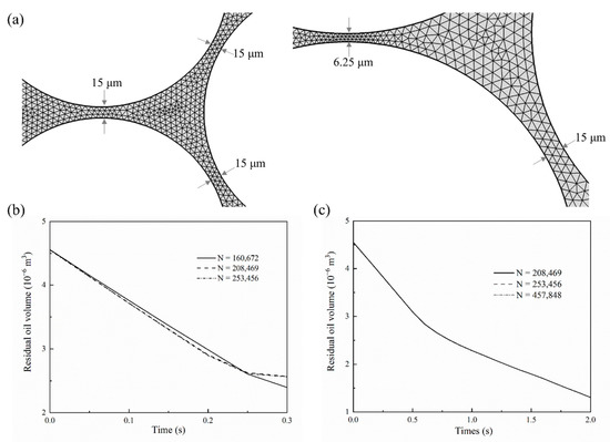
Figure 3.
(a) Finite element mesh used in numerical simulations, (b) mesh independence tests for immiscible and near-miscible flooding models, and (c) mesh independence tests for miscible flooding model.
3. Results and Discussion
3.1. Flow Behaviors and Oil Recovery under Different Conditions
The temporal evolution of the computed CO2 saturation distribution under immiscible and near-miscible conditions is shown in Figure 4a,b; the calculated CO2 concentration evolution under the miscible condition is presented in Figure 4c. The different particle sizes lead to pore structure heterogeneity, which, accordingly, causes the fingering under all three conditions. Comparatively, immiscible flooding has the smallest capillary number (, Ca =3.31 × 10⁻⁵). The smaller Ca means that the capillary force exerts stronger effects on CO2 migration [41,42]. The CO2 plume mostly migrates through the larger pore throat, which is formed by the small grains and has smaller capillary resistance (Figure 4a). The final oil recovery efficiency is low and only reaches ~35% (Figure 5). Compared with immiscible flooding, the fingering of near-miscible flooding is improved to a certain extent. Due to smaller interfacial tension, CO2 can invade more normal pore throats that CO2 cannot enter under immiscible conditions (see the region enclosed by the dotted ellipse in Figure 4b), and, thus, the sweep areas become larger and the fingering numbers increase (Figure 4b). Final oil recovery can reach ~50%, which is about 40% higher than the value under immiscible conditions. It needs to be indicated that after the CO2 phase breaks through the porous media, the residual oil in pores cannot be displaced by continued CO2 injection any more under the immiscible condition, while under the near-miscible condition, the oil in some pores can still be replaced by continued CO2 injection, which is also consistent with the experimental observations of Cao and Gu [8].
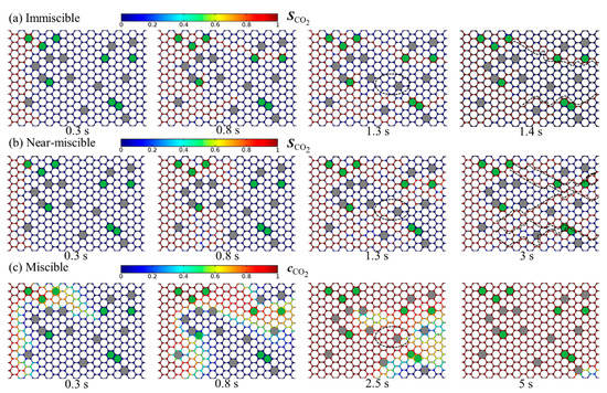
Figure 4.
Temporal evolution of the calculated CO2 saturation distribution under (a) immiscible and (b) near-miscible conditions as well as the calculated CO2 concentration distribution under (c) the miscible condition. The dotted line marks the CO2 finger path; the dotted ellipse indicates the increased CO2 sweep area under the near-miscible condition compare to the immiscible condition.
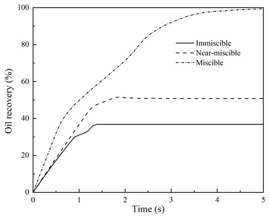
Figure 5.
Oil recovery under immiscible, near-miscible, and miscible conditions.
Under the miscible condition, due to no CO2–oil interfacial intension, CO2 migration will only be controlled by fluid pressure. In this case, unlike immiscible and near-miscible flooding, there is no capillary resistance that will cause fingering. According to the bundle of tubes assumption [43,44], the viscous flow volumetric flow rate is directly related to the fourth power of pore radius, based on the Hagen–Poiseuille equation, and the volumetric flow rate of diffusion is proportional to pore radius square, according to Fick’s first law [45]. Pore structure heterogeneity caused by various particle sizes can affect fluid flow and CO2–oil diffusion during CO2 migration. When pores with different sizes compete for mass transfer under the same concentration or pressure gradient, large pores will be preferred since the volumetric flow rate may differ by several orders of magnitude when considering a relatively small difference in pore size at the pore scale, which is in accordance with the experimental results of Chen and Mohanty [45]. Thus, although interfacial tension does not exist in the miscible condition, CO2/oil flow behaviors under the miscible condition still depend on pore size since both viscous flow and diffusion are pore-size-dependent. At the initial stage of flooding, the CO2 plume still migrates along the large pore throat. After CO2 breaks through the porous media, CO2 gradually penetrates the small pore throats with the continuous injection of CO2, which leads to a substantial increase in oil recovery. Such a process is consistent with the experimental observations of Cao and Gu [8]. Finally, CO2 displacement efficiency exceeds 90% (Figure 5), which is far beyond the values under immiscible and near-miscible conditions.
Pore parameters of the assumed porous media in this study are equivalent to those of some sandstone oil reservoirs [46]. Despite relatively good pore connectivity and pore properties, these sandstones inevitably have pore structure heterogeneity. For such reservoirs, the miscible flooding method will be able to largely relieve the effects of heterogeneity on oil recovery and, thus, can be used as a primary choice. Compared to miscible flooding, the capacity of near-miscible flooding to increase oil recovery is very limited. The residual oil in a considerable number of small pores cannot be replaced by such a flooding method.
When conducting field-scale numerical simulations, the model parameters of controlling CO2/oil flow behavior are mainly absolute permeability, relative permeability, and capillary pressure. However, these parameters are difficult to specify reasonably, especially under near-miscible and miscible conditions. Our pore-scale modeling shows that when specifying these parameters, the residual oil saturation parameter of the relative permeability curve and the capillary pressure magnitude under the near-miscible condition should be somewhat lower than those used under the immiscible condition, whereas capillary pressure magnitude is close to zero and the residual oil saturation parameter is much lower under the miscible condition [47].
3.2. Effects of CO2 Injection Velocity on Oil Recovery under Immiscible and Near-Miscible Conditions
Increasing the flow rate of CO2 is usually one of the most important ways for CO2-EOR to decrease residual oil at the field scale [2]. Thus, we also compared the calculated oil recovery at different CO2 injection velocities (0.01 and 0.05 m/s) under immiscible and near-miscible conditions at the pore scale. As shown in Figure 6, under the immiscible condition, a bigger injection velocity has better oil recovery performance, which is consistent with the experimental observations and simulation results of previous studies [23,42,48]. The enhancement of injection velocity leads to an increase of 7% in oil recovery. Under the near-miscible condition, the increasing injection velocity significantly speeds up the flooding process. In less than 0.3 s, CO2 breaks through the porous media, while at the lower velocity, the time exceeds 0.8 s, as shown in Figure 7. Due to the shortened breakthrough time during which displacement mainly occurs, the sweep area becomes smaller at the bigger CO2 injection velocity. Consequently, the increasing injection velocity contributes very little to the enhancement of oil recovery and even has a negative effect on oil recovery. Final oil recovery at uin = 0.05 m/s is about 40%, which is lower than the value (~50%) at uin = 0.01 m/s. All of these inferences are also consistent with the experiment results of Abedini et al. [48], which indicated that ultimate oil recovery was much less dependent on CO2 injection velocity under near-miscible conditions and that increasing the injection velocity of CO2 cannot increase oil recovery under the immiscible condition either.
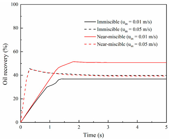
Figure 6.
Oil recovery at the injection velocity of 0.01 and 0.05 m/s, respectively, under immiscible and near-miscible conditions.
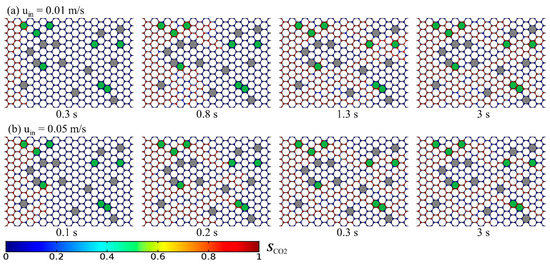
Figure 7.
Temporal evolution of CO2 distribution under the near-miscible condition at the CO2 injection velocity of (a) 0.01 m/s and (b) 0.05 m/s.
For immiscible flooding, even if the injection velocity is significantly increased, oil recovery is only slightly increased. However, it can largely shorten the injection time of CO2 at the same oil recovery rate, which substantially saves the time cost of CO2-EOR projects. For near-miscible flooding, if injection velocity is increased, oil recovery does not increase but somewhat decreases. Therefore, low injection velocity of CO2 is a more beneficial choice under near-miscible conditions for CO2-EOR projects to pursuit higher oil recovery.
3.3. Effects of Different Diffusion Coefficients on Oil Recovery under the Miscible Condition
The rate at which CO2 diffuses in oil is an important parameter for CO2-EOR, but it is often uncertain [49]. Temperature varies in a range from 298 to 423 K for most oil reservoirs. The CO2 diffusion coefficient generally increases with increasing temperature, and the CO2 diffusion coefficient lies in a wide range from 1 × 10⁻¹⁰ to 1 × 10⁻⁷ m2/s [34]. The calculated temporal and spatial evolution of the dissolved CO2 plume when the CO2 diffusion coefficient is, respectively, equal to (a) 1 × 10⁻⁹ and (b) 1 × 10⁻⁷, which correspond to two different Péclet numbers (; 3500 and 35), are shown in Figure 8. We identify the flow behavior of CO2 under the miscible condition through the tracking of concentration iso-surfaces, herein referred to as the concentration front interface. The viscous fingering is the dominant transport regime at the beginning of flooding (Figure 8b). As Pe increases, both heterogeneity-induced channeling and viscous fingering still occur. The effect of the different Pe on miscible displacement in heterogeneous porous media was also simulated by Afshari et al. [39]. The preferred flow paths are the ones with the smallest resistance to flow and transport in the porous media.
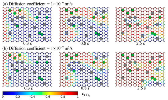
Figure 8.
Temporal and spatial evolution of the dissolved CO2 plume when the CO2 diffusion coefficient is, respectively, equal to (a) 1 × 10⁻⁹ m/s and (b) 1 × 10⁻⁷ m/s.
The effects of the different diffusion coefficients on oil recovery are small. As shown in Figure 9, the deviation in calculated oil recovery caused by the different diffusion coefficients is smaller and less than 5%. This implies that the increased diffusion coefficient contributes very little to oil recovery under the miscible condition, which is in agreement with the existing work in the literature [49]. In comparison, better oil recovery would be obtained with miscible CO2 flooding in fractured porous media with diffusion coefficients increased [50].
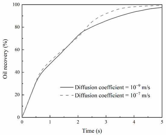
Figure 9.
Oil recovery at the diffusion coefficient of 1 × 10⁻⁹ and 1 × 10⁻⁷ m/s under the miscible condition.
4. Conclusions
Based on pore-scale numerical simulations of CO2/oil flow behavior in heterogeneous porous media at various flooding conditions, the following conclusions can be drawn:
- (1)
- Pore structure heterogeneity causes obvious fingering under the immiscible condition, significantly lowers the sweep area, and leads to a considerable amount of residual oil. Comparatively, near-miscible flooding can somewhat increase the sweep area and improve CO2/oil displacement efficiency. However, it is still inefficient to displace oil in small pore throats.
- (2)
- Increasing CO2 injection velocity only contributes a little to the enhancement of oil recovery efficiency under the immiscible condition, whereas it has a negative effect on oil recovery efficiency under the near-miscible condition due to shorter CO2 breakthrough time. If immiscible or near-miscible flooding is used, a high CO2 injection velocity will largely speed up oil recovery while maintaining equivalent oil recovery efficiency for immiscible flooding, while low CO2 injection velocity can be beneficial to further enhancing oil recovery efficiency under the near-miscible condition.
- (3)
- For miscible flooding, CO2 preferentially displaces oil through big throats and, subsequently, invades small pore throats, which substantially increases oil recovery efficiency. Thus, CO2 miscible flooding is the preferential option for oil reservoirs with strong pore-structure heterogeneity and large amounts of small pore throats. However, strengthening CO2 diffusion in oil cannot enhance the oil recovery efficiency of miscible flooding.
Author Contributions
Conceptualization, D.W.; data curation, Q.W.; formal analysis, J.B.; funding acquisition, D.W. and W.W.; investigation, J.J. and M.L.; methodology, Q.M.; project administration, D.W.; resources, P.H.; software, Q.M.; supervision, D.W.; validation, Z.Z. and J.F.; visualization, Z.Z.; writing—original draft, Q.M.; writing—review and editing, D.W. All authors were informed about each step of manuscript processing, including submission, revisions, and reminders, via emails from our system or an assigned Assistant Editor. All authors have read and agreed to the published version of the manuscript.
Funding
This research was funded by the National Science Foundation of China (grant number 51776030), the Dalian Leading Academic and Key Plan Project (grant number 2020JJ25CY010), and the PetroChina Innovation Foundation (grant number 2017D-5007-0210).
Institutional Review Board Statement
Not applicable.
Informed Consent Statement
Not applicable.
Data Availability Statement
Data available in a publicly accessible repository.
Acknowledgments
This work was supported by the National Science Foundation of China (51776030), the Dalian Leading Academic and Key Plan Project (2020JJ25CY010), and the PetroChina Innovation Foundation (2017D-5007-0210).
Conflicts of Interest
The authors declare no conflict of interest.
References
- Vochozka, M.; Rowland, Z.; Suler, P.; Marousek, J. The influence of the international price of oil on the value of the EUR/USD exchange rate. J. Compet. 2020, 12, 167. [Google Scholar] [CrossRef]
- Green, D.W.; Willhite, G.P. Enhanced Oil Recovery, 2nd ed.; Henry, L., Ed.; Doherty Memorial Fund of AIME, Society of Petroleum Engineers: Richardson, TX, USA, 2018. [Google Scholar]
- Jia, B.; Tsau, J.S.; Barati, R. A review of the current progress of CO2 injection EOR and carbon storage in shale oil reservoirs. Fuel 2019, 236, 404–427. [Google Scholar] [CrossRef]
- Zhang, N.; Wei, M.Z.; Bai, B.J. Statistical and analytical review of worldwide CO2 immiscible field applications. Fuel 2018, 220, 89–100. [Google Scholar] [CrossRef]
- IEA. World Energy Outlook 2018 EOR database. 2018. Available online: https://iea.blob.core.windows.net/assets/f9887a84-26bb-44cb-a8fa-20a5797ceb59/ (accessed on 28 November 2018).
- Abedini, A.; Torabi, F. Oil recovery performance of immiscible and miscible CO2 huff-and-puff processes. Energy Fuels 2014, 28, 774–784. [Google Scholar] [CrossRef]
- Wang, X.Q.; Gu, Y.A. Oil recovery and permeability reduction of a tight sandstone reservoir in immiscible and miscible CO2 flooding processes. Ind. Eng. Chem. Res. 2011, 50, 2388–2399. [Google Scholar] [CrossRef]
- Cao, M.; Gu, Y.G. Oil recovery mechanisms and asphaltene precipitation phenomenon in immiscible and miscible CO2 flooding processes. Fuel 2013, 109, 157–166. [Google Scholar] [CrossRef]
- Torabi, F.; Firouz, A.Q.; Kavousi, A.; Asghari, K. Comparative evaluation of immiscible, near miscible and miscible CO2 huff-n-puff to enhance oil recovery from a single matrix-fracture system (experimental and simulation studies). Fuel 2012, 93, 443–453. [Google Scholar] [CrossRef]
- Alizadeh, A.H.; Piri, M. Three-phase flow in porous media: A review of experimental studies on relative permeability. Rev. Geophys. 2014, 52, 468–521. [Google Scholar] [CrossRef]
- Shaver, R.D.; Robinson, R.L.; Gasem, K.A.M. An automated apparatus for equilibrium phase compositions, densities, and interfacial tensions: Data for carbon dioxide plus decane. Fluid Phase Equilibr. 2001, 179, 43–66. [Google Scholar] [CrossRef]
- Georgiadis, A.; Llovell, F.; Bismarck, A.; Blas, F.J.; Galindo, A.; Maitland, G.C.; Trusler, J.P.M.; Jackson, G. Interfacial tension measurements and modelling of (carbon dioxide plus n-alkane) and (carbon dioxide plus water) binary mixtures at elevated pressures and temperatures. J. Supercrit. Fluid 2010, 55, 743–754. [Google Scholar] [CrossRef]
- Shen, Z.Q.; Sheng, J.J. Experimental and numerical study of permeability reduction caused by asphaltene precipitation and deposition during CO2 huff and puff injection in Eagle Ford shale. Fuel 2018, 211, 432–445. [Google Scholar] [CrossRef]
- Chen, C.; Zhang, D.X. Pore-scale simulation of density-driven convection in fractured porous media during geological CO2 sequestration. Water Resour. Res. 2010, 46. [Google Scholar] [CrossRef]
- Picchi, D.; Battiato, I. Relative permeability scaling from pore-scale flow regimes. Water Resour. Res. 2019, 55, 3215–3233. [Google Scholar] [CrossRef]
- Bear, J. Dynamics of Fluids in Porous Media; Dover Publications, Inc.: New York, NY, USA, 1972. [Google Scholar]
- Blunt, M.J. Multiphase Flow in Permeable Media: A Pore-Scale Perspective; Cambridge University Press: Cambridge, UK, 2017. [Google Scholar] [CrossRef]
- Shyeh-Yung, J.G.J. Mechanisms of miscible oil recovery: Effects of pressure on miscible and near-miscible displacements of oil by Carbon Dioxide. In SPE Annual Technical Conference and Exhibition; Society of Petroleum Engineers: Dallas, TX, USA, 1991; p. 15. [Google Scholar] [CrossRef]
- Taber, J.J. Technical Screening Guides for the Enhanced Recovery of Oil; SPE Annual Technical Conference and Exhibition; Society of Petroleum Engineers: San Francisco, CA, USA, 1983. [Google Scholar] [CrossRef]
- Sohrabi, M.; Danesh, A.; Tehrani, D.H.; Jamiolahmady, M. Microscopic mechanisms of oil recovery by near-miscible gas injection. Transp. Porous. Med. 2008, 72, 351–367. [Google Scholar] [CrossRef]
- Chen, H.; Li, B.; Duncan, I.; Elkhider, M.; Liu, X. Empirical correlations for prediction of minimum miscible pressure and near-miscible pressure interval for oil and CO2 systems. Fuel 2020, 278, 118272. [Google Scholar] [CrossRef]
- Renner, T.A. Measurement and correlation of diffusion coefficients for CO2 and rich-gas applications. SPE Reserv. Eng. 1988, 3, 517–523. [Google Scholar] [CrossRef]
- Zhu, G.P.; Yao, J.; Li, A.F.; Sun, H.; Zhang, L. Pore-scale investigation of carbon dioxide-enhanced oil recovery. Energ. Fuel 2017, 31, 5324–5332. [Google Scholar] [CrossRef]
- Lashgari, H.R.; Sun, A.; Zhang, T.W.; Pope, G.A.; Lake, L.W. Evaluation of carbon dioxide storage and miscible gas EOR in shale oil reservoirs. Fuel 2019, 241, 1223–1235. [Google Scholar] [CrossRef]
- Yue, P.T.; Feng, J.J.; Liu, C.; Shen, J. A diffuse-interface method for simulating two-phase flows of complex fluids. J. Fluid Mech. 2004, 515, 293–317. [Google Scholar] [CrossRef]
- Cahn, J.W.; Hilliard, J.E. Free Energy of a Nonuniform System. I. Interfacial Free Energy. J. Chem. Phys. 1958, 28, 258–267. [Google Scholar] [CrossRef]
- Garmeh, G.; Johns, R.T.; Lake, L.W. Pore-scale simulation of dispersion in porous media. Spe J. 2009, 14, 559–567. [Google Scholar] [CrossRef]
- Lee, S.; Wheeler, M.F. Adaptive enriched Galerkin methods for miscible displacement problems with entropy residual stabilization. J. Comput. Phys. 2017, 331, 19–37. [Google Scholar] [CrossRef]
- Hoteit, H. Modeling diffusion and gas-oil mass transfer in fractured reservoirs. J. Pet. Sci. Eng. 2013, 105, 1–17. [Google Scholar] [CrossRef]
- Mohammadmoradi, P.; Taheri, S.; Bryant, S.L.; Kantzas, A. Solvent diffusion and dispersion in partially saturated porous media: An experimental and numerical pore-level study. Chem. Eng. Sci. 2018, 191, 300–317. [Google Scholar] [CrossRef]
- Pini, R.; Krevor, S.C.M.; Benson, S.M. Capillary pressure and heterogeneity for the CO2/water system in sandstone rocks at reservoir conditions. Adv. Water Resour. 2012, 38, 48–59. [Google Scholar] [CrossRef]
- Yue, P.T.; Zhou, C.F.; Feng, J.J.; Ollivier-Gooch, C.F.; Hu, H.H. Phase-field simulations of interfacial dynamics in viscoelastic fluids using finite elements with adaptive meshing. J. Comput. Phys. 2006, 219, 47–67. [Google Scholar] [CrossRef]
- Cuiec, L.E. Evaluation of reservoir wettability and its effect on oil recovery. In Interfacial Phenomena in Petroleum Recovery; Morrow, N.R., Ed.; Marcel Dekker: New York, NY, USA, 1991; Chapter 9; pp. 319–375. [Google Scholar]
- Wang, L.Z.; Yu, W. Mechanistic simulation study of gas Puff and Huff process for Bakken tight oil fractured reservoir. Fuel 2019, 239, 1179–1193. [Google Scholar] [CrossRef]
- Dumore, J.M. Stability considerations in downward miscible displacements. Soc. Pet. Eng. J. 1964, 231, 356–362. [Google Scholar] [CrossRef]
- Tan, C.T.; Homsy, G.M. Stability of miscible displacements in porous media-Radial source flow. Phys. Fluids 1987, 30, 1239–1245. [Google Scholar] [CrossRef]
- Koval, E.J. A method for predicting the performance of unstable miscible displacement in heterogeneous media. Soc. Pet. Eng. J. 1963, 3, 145–154. [Google Scholar] [CrossRef]
- Stalkup, F.I. Miscible Displacement; Monograph Series; SPE: Richardson, TX, USA, 1983; Volume 8. [Google Scholar]
- Afshari, S.; Hejazi, S.H.; Kantzas, A. Role of medium heterogeneity and viscosity contrast in miscible flow regimes and mixing zone growth: A computational pore-scale approach. Phys. Rev. Fluids 2018, 3, 054501. [Google Scholar] [CrossRef]
- Comsol, A. CFD Module s User’s Guide; COMSOL Inc.: Stockholm, Sweden, 2017. [Google Scholar]
- Lenormand, R.; Touboul, E.; Zarcone, C. Numerical models and experiments on immiscible displacements in porous media. J. Fluid Mech. 1988, 189, 165–187. [Google Scholar] [CrossRef]
- Zhang, C.Y.; Oostrom, M.; Wietsma, T.W.; Grate, J.W.; Warner, M.G. Influence of viscous and capillary forces on immiscible fluid displacement: Pore-scale experimental study in a water-wet micromodel demonstrating viscous and capillary fingering. Energy Fuels 2011, 25, 3493–3505. [Google Scholar] [CrossRef]
- Carman, P.C. Fluid flow through granular beds. Trans. Inst. Chem. Eng. 1937, 15, 150–166. [Google Scholar] [CrossRef]
- Kozeny, J. Uber kapillare leitung der wasser in boden. R. Acad. Sci. Viennaproc. Cl. I 1927, 136, 271–306. [Google Scholar]
- Chen, X.Y.; Mohanty, K.K. Pore-scale mechanisms of immiscible and miscible gas injection in fractured carbonates. Fuel 2020, 275. [Google Scholar] [CrossRef]
- Chen, T.; Yang, Z.M.; Luo, Y.T.; Lin, W.; Xu, J.X.; Ding, Y.H.; Niu, J.L. Evaluation of displacement effects of different injection media in tight oil sandstone by online nuclear magnetic resonance. Energies 2018, 11, 2836. [Google Scholar] [CrossRef]
- Jia, B.; Tsau, J.S.; Barati, R. Role of molecular diffusion in heterogeneous, naturally fractured shale reservoirs during CO2 huff-n-puff. J. Pet. Sci. Eng. 2018, 164, 31–42. [Google Scholar] [CrossRef]
- Abedini, A.; Torabi, F.; Mosavat, N. Performance of immiscible and miscible CO2 injection process in a tight carbonate reservoir (experimental and simulation approach). Int. J. Oil Gas Coal T 2015, 9, 265–279. [Google Scholar] [CrossRef]
- Yu, W.; Lashgari, H.R.; Wu, K.; Sepehrnoori, K. CO2 injection for enhanced oil recovery in Bakken tight oil reservoirs. Fuel 2015, 159, 354–363. [Google Scholar] [CrossRef]
- Hoteit, H.; Firoozabadi, A. Numerical Modeling of Diffusion in Fractured Media for Gas Injection and Recycling Schemes. In Proceedings of the SPE Annual Technical Conference and Exhibition; Society of Petroleum Engineers: San Antonio, TX, USA, 2006; p. 15. [Google Scholar] [CrossRef]
Publisher’s Note: MDPI stays neutral with regard to jurisdictional claims in published maps and institutional affiliations. |
© 2021 by the authors. Licensee MDPI, Basel, Switzerland. This article is an open access article distributed under the terms and conditions of the Creative Commons Attribution (CC BY) license (http://creativecommons.org/licenses/by/4.0/).