1. Introduction
Military motor vehicles (tanks, armored personnel carriers, infantry fighting vehicles) are mainly operated off-road, in sandy or desert terrain, where mineral dust concentration in the air is particularly high and often exceeds a value of 1 g/m
3. The authors [
1] state that the dust concentration when vehicles are column driving on a sandy area reaches 0.03–8 g/m
3. During the take-off or landing of a helicopter at an accidental landing site, dust concentration at the height of the tip of the CH-53 helicopter’s propeller (0.5 m above the ground) may reach a value of
s = 3.33 g/m
3 [
2]. According to the authors [
3,
4,
5,
6], the maximum dust concentration at the inlet to the inlet system of the vehicle’s internal combustion engine usually does not exceed a value of 2.5 g/m
3. There are two basic dust components: SiO
2 silica and Al
2O
3 alumina, whose composition of the dust reaches 95%, and they are also characterized by having the highest hardness. In the ten-degree Mohs scale, silica has a hardness of seven and corundum is a nine. Thus, their hardness exceeds that of the structural materials used for the components (cylinder liners, crankshaft journals and camshafts) in internal combustion engines. Moreover, mineral dust grains have very irregular shapes with sharp edges. Most dangerous for two cooperating engine components are dust particles whose diameter
dp is equal to oil film thickness
hmin between two surfaces at that moment. In an internal combustion engine, there are many elements that cooperate in movement and are lubricated with oil. Oil film thickness depends on the engine operating parameters and oil properties, and therefore they assume various values—most often in the range of
hmin = 0–10 µm [
7,
8]. Dust sucked in with the air enters the piston, which makes the cylinder and piston top degrade the most, as well as the top piston rings. Abrasive engine component degradation is caused mainly by particles with a size of 1–40 µm, with the most dangerous dust grains in the range of 1–20 µm [
9,
10,
11]. Dust grains below 50–100 µm are simply sucked in with the intake air. It follows that the intake air filters in internal combustion engines should retain all dust grains above 1 µm. This is a complicated problem considering that military vehicles are most often equipped with combustion engines with high power and high air demand, with which a significant dust mass enters. For example, the engine of a PT-91 tracked vehicle with a capacity of 700 kW draws in more than 3400 m
3/h of atmospheric air per hour. If the dust concentration in the air is 2.5 g/m
3, the motor draws in more than 8 kg of dust per hour along with the air.
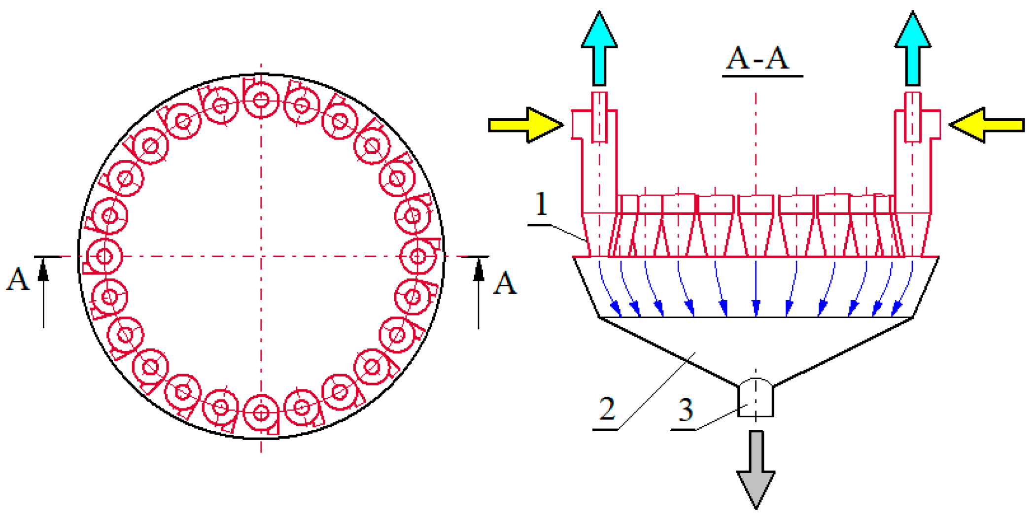
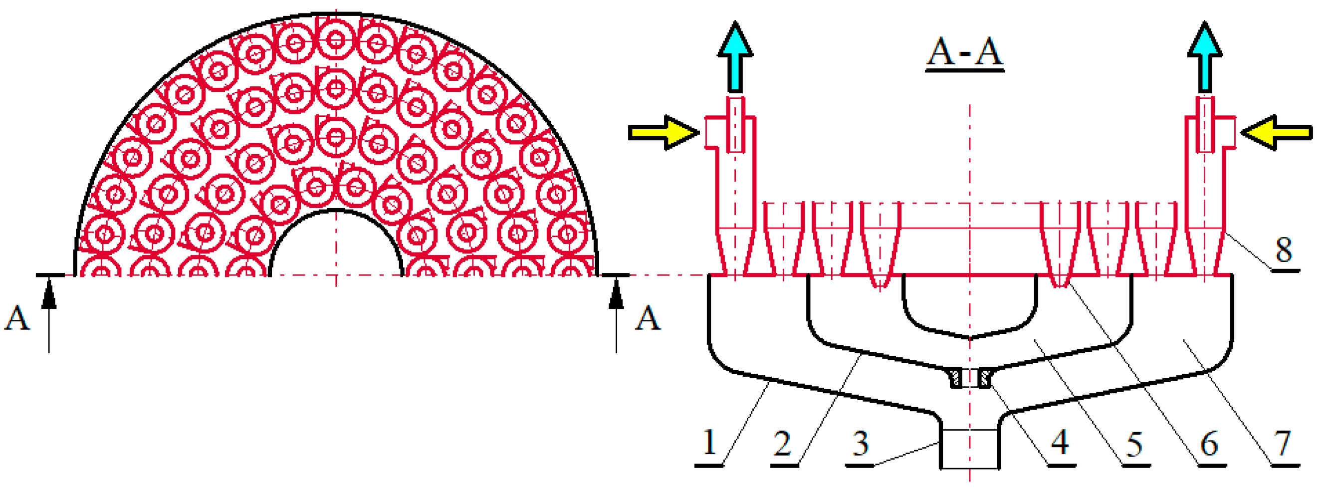
To remove such a large dust mass in a short time with the required efficiency of 99.5% and an accuracy above 1 µm, two-stage air filters are used, which differ in their principle and operation mode, design, separation barrier type, and operation efficiency. The first stage of air separation is a multi-cyclone, which is a group of individual cyclones arranged in parallel (next to each other), fixed with their ends in common lower and upper plates, which guarantee a common air inlet and outlet—
Figure 1.
The second stage of air separation is a partition element (filter cartridge), which, due to space limitations and the desire to increase filter material surface area, is most often made of a pleated filter paper. The operation essence of the “multi-cyclone-porous partition” filter is that the multi-cyclone is characterized by the possibility of separating large dust masses from the polluted air without increasing pressure drop, but with much lower efficiency (87–95%) and accuracy (
dp > 15–35 µm) than a paper filter. The remaining insignificant dust mass is then directed to the filter element, most often made of pleated paper, having a low and limited absorbency (in the range of 150–250 g/m
2), but characterized by high accuracy (above
dp = 2–5 µm) and high separation efficiency (above
φ = 99.5%) [
11,
12,
13,
14,
15,
16]. As a result, air is supplied to the engine cylinders with the required purity and, at the same time, the operation time of the separation system is extended. Thus, the vehicle’s service interval, which is limited by the achievement of a certain pressure drop value, is the permissible resistance Δ
pfdop.
Significant dust masses separated by the cyclones are collected in a multi-cyclone dust settling tank common to all cyclones. During eight hours of PT-91 vehicle use, the multi-cyclone filter, operating with 90% efficiency, can separate over 60 kg of dust, the storage of which requires a sedimentation tank with a capacity of over 25 dm3. Storing a large dust mass in a multi-cyclone settler is not recommended due to the unnecessary load on the filter structure and the additional mass in the vehicle. The use of a large-capacity sludge trap increases the filter dimensions, which is especially undesirable for military vehicles. In addition, there are unfavorable phenomena:
During vehicle shocks and sudden changes in the engine speed: There are rapid changes in the air stream, which causes undesirable suction by the cyclone of dust accumulated in the settling tank,
As a result of the settling tank completely filling: The dust does not settle in the settling tank, but it is entrained, and thus cyclone separation efficiency decreases.
For this reason, in two-stage multi-cyclone air filters in vehicle engines used in areas of high dust concentration conditions in the air (tanks, infantry fighting vehicles, armored personnel carriers), systematic dust removal from the settling tank in a continuous manner is used. For this purpose, an additional air stream is used—the
QS suction stream—and the phenomenon of ejection is used to create it. The
QS flux value is obtained by using special fans or blowers driven by electric motors and powered by an on-board battery, which adversely affects the vehicle’s energy balance. For this reason, in many air filter solutions for generating suction stream, appropriate ejectors that use the energy of the compressed air stream are used as a device for forcing the flow [
17,
18,
19,
20] or exhaust gases out of the engine exhaust system [
21,
22,
23].
Removal (by suction) of the separated and collected dust from the cyclone settling tank causes a noticeable increase in its separation efficiency, but only to a certain value of the suction degree—which usually does not exceed
m0 = 10–15% [
24,
25]. On the other hand, the available multi-cyclones design solutions analysis and their dust extraction systems from the settling tank, as well as the studies presented in [
26], show that the connection of the dust discharge holes of several dozen cyclones into a common and tight space (dust settler) from which extraction takes place pointwise (with two or one stub pipe) and then causes different values (up to 50%) for the suction streams. In a multi-cyclone consisting of a large number (several dozen) of cyclones with a common dust trap, the use of only one or two dust extraction nozzles from the settling tank causes the outlet opening distances of the individual cyclones, which suction away from the extraction system stub, to be unequal. This naturally creates differences between the resistances in the flow and individual stream values that are suctioned out. This may have a negative impact on the proper operation of the multi-cyclone, as it reduces the separation efficiency of individual cyclones and, consequently, of the entire multi-cyclone. According to the author [
27,
28], this phenomenon results from the uneven distribution of the air stream into individual cyclones, and even the reverse flow occurrence in the cyclones is located on the periphery of the multicyclone, which causes different characteristics in the adjacent cyclones.
The highest suction stream values
QSc from individual cyclones occur, regardless of the value of the main suction stream from the
QSF settling tank, for cyclones located closest to the dust suction nozzle of the settling tank. As the position of successive cyclones moves away from the suction stub pipe, the suction stream values
QSc systematically decrease, and for the furthest cyclones they assume values that are lower by 35–50% [
26].
The uniform suction stream values from the individual cyclones of a multi-cyclone made of several dozen cyclones can be ensured by using a method that maintains the symmetry of the position of all the cyclones in relation to the suction nozzle, or by a method of creating suction streams that are equal to the resistance by dividing the settling space into independent segments and channels covering a specific number of cyclones. The application of a specific method depends on the number and type of cyclones, space limitations at the place of multi-cyclone installation, and the possibility of carrying out an appropriate scope of tests.
This work [
29] presents a multi-cyclone design intended to study the minimization effect on suction uniformity of individual cyclones by removing the suction stream method from the separation chamber (dust settler). The multi-cyclone consists of 24 through-flow cyclones with an axial inlet, closed in a rectangular cassette, to which a dust trap is tightly attached at the bottom. Dust extraction from the common settling tank takes place through four separate nozzles, shaped in such a way that they form narrowing channels. The same air flow rate was ensured in each stub pipe. Experimental studies of the multi-cyclone for various suction rates, and with a variable air flow velocity through a single cyclone, showed that for a single cyclone, under comparable flow conditions and the same suction degree, the multi-cyclone separation efficiency would be 5–7% lower [
29]. This simple dust removal solution from the settling tank significantly reduces the uneven suction from cyclones but does not completely eliminate it.
According to the authors [
30], a more effective method of reducing the unevenness of the suction from the cyclones is the multi-cyclone modular structure. The module presented [
30] is a cassette with a square cross-section in which there are four symmetrically placed through-flow cyclones with an axial inlet—depicted in
Figure 2. A multi-cyclone consists of six such modules, which are arranged in two rows next to each other.
The module dust collector has been divided into partitions so that the outlet windows of the individual cyclones are isolated from each other. Each module has a separate settler from which dust is sucked through a centrally located duct. Dust extraction ducts from the six modules are connected into one common collector, from which extraction is performed by one duct. The presented design steps were dictated by efforts to eliminate the interaction of the swirled streams flowing out of the individual cyclones in the module. The performed experimental tests on the module showed that its characteristics did not differ significantly from the characteristics of a single cyclone, both in terms of course and value, which means that the suction from all four cyclones is identical. This means that the pollutants suction method from the dust collector of the module is appropriate. The experimental performance studies of the entire modular multi-cyclone also did not show a decrease in efficiency in relation to a single cyclone. However, due to the use of a rather complex system of suction lines inside the connector, the pressure drop of this multi-cyclone has increased by about 15% compared to a single module.
The problem of organizing the suction process and minimizing uneven suction from the settling tank of the radial filter, which is composed of three identical modules, is presented in this work [
31]. The dust separated from the air stream flowing through the filter collects in the separation channels from where it enters the dust trap common for all modules, which is a pipe with a constant cross-section—depicted in
Figure 3. The separation efficiency is determined for the rated conditions of air flow through the filter, which was within the range of 33–40%, and, when compared to the efficiency of a single module (60–61%), is a very small value. The individual performance of each module, as part of the filter assembly, showed that module
a, which was the closest to the outlet of the sedimentation tank, achieved an efficiency of 64%, and showed that module
b achieved an efficiency of 43%, while module
c, the furthest from the outlet of the suction port, only had an efficiency of 20% [
31]. Such significant differences in the modules’ efficiencies are the result of the divergent suction levels in the modules, and this is due to the unequal distances of their separation channels from the suction stub of the dust settler. The authors [
31] solved the problem of equalizing the suction streams in this type of filter by dividing the dust trap into three parts (channels) according to the diagram shown in
Figure 3b.
After appropriate selection of the heights h1 and h2, similar values for the suction streams from all modules were obtained. Thus, a significant improvement in the uniformity of operation of all the modules was achieved (maximum efficiency differences did not exceed 7%) and there was a clear improvement (up to 60.6%) in the efficiency of the entire radial filter.
The above-mentioned examples show how important an influence on the operation of the inertial filter is for development of the correct suction system. Regardless of the equalizing suction stream values method, an experimental verification of the system is always required, consisting of measuring the values of the individual suction streams from all cyclones, segments, or multi-cyclone modules.
The problem of dust accumulation in a single cyclone settler and the impact of the settler dimensions on the efficient operation of the cyclones is presented in this work [
32,
33,
34,
35,
36].
The authors [
32], after examining the influence of the dimensions of the cylindrical dust trap (height and diameter) on cyclone operation, showed that the optimal design of the sedimentation tank and the dipleg (the extended part of the bottom part of the cyclone, connecting the cyclone with the dust trap) leads to a better separation efficiency than a conventional cyclone. The authors [
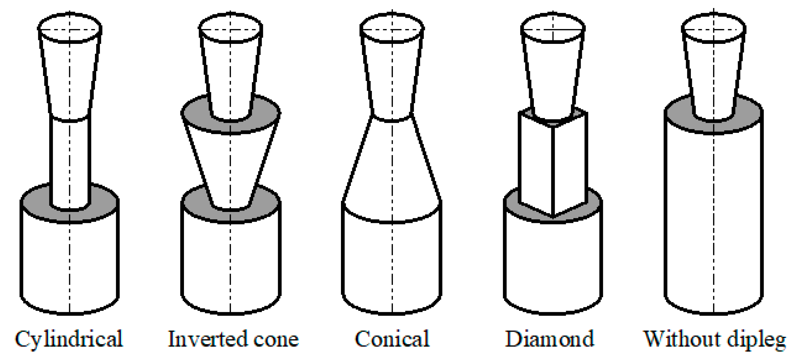
33], using the CFD program, investigated the influence that the influence that dipleg shape (cylindrical, inverted cone, conical and diamond) has has on the flow characteristics and cyclone operation—depicted in depicted in
Figure 4.
It was found that the dipleg geometry significantly influences the the cyclone pressure drop. The cylindrical dipleg generated the highest pressure drop, while the lowest pressure drop was observed for the cyclone without a dipleg. Among tested geometries, the highest separation efficiency was found for the cyclone with a conical dipleg, and diamond dipleg was the lowest.
The authors of [
34] numerically examined the particle separation process inside two cyclones extended with a dipleg. They found that the dipleg length significantly influences the cyclone’s separation efficiency by providing more separation space and minimizing re-lift of the separated particles.
Paper [
35] presents research results on three cyclones separation efficiency with different lengths of cylindrical diplegs and with a dust trap of a constant shape. It was shown that tangential velocity, axial velocity and turbulent kinetic energy in the settling tank decreased significantly when the dipleg length was extended. This means that a dust collector with a dipleg can effectively prevent the re-entrainment of already separated dust. In addition, the elongated part of dipleg increases dust separation space, and thus separation efficiency increases, at the expense of a slightly increased pressure drop.
Authors [
36] investigated experimentally cyclones with three different geometries of dust outlet from cyclone: a cyclone with a dust trap, with a cone at cyclone outlet, and a cyclone with a cylindrical dipleg. They found that in the case of a cyclone with only a dust trap, the swirling stream passes from the cyclone cone to the settler, which will cause the collected particles to be entrained again. In case of cyclone with a tip cone, efficiency improvement in cyclone has been achieved. They showed that separation efficiency can be significantly improved by changing dust collector geometry.
One of the methods of increasing cyclone separation efficiency is to attach an additional element (cone) at the dust outlet from the cyclone to the settling tank. The task of this element, also known as the apex cone, is to limit the secondary circulation of the separated dust particles. It is very important to precisely select cone diameter, the apex angle and its proper position. Incorrect selection of these parameters may block the bottom outlet of the cyclone and make it difficult for dust to fall into the tank, and thus reduce cyclone separation efficiency. Therefore, [
37] influence of fifteen variants of the geometrical configurations of the counter-cone on cyclone efficiency was analyzed. The cone geometry was determined by the following parameters (
Figure 5): cone diameter
DS, apex angle
α, and distance from the cone base to the cyclone bottom outlet with diameter
Bh, for cyclone outlet diameter
B.
It was found that cone use in each of investigated geometric variants led to cyclone efficiency increase. The results show that the optimal position of the cone (assuming separation efficiency is maximized) should be above the bottom outlet of the cyclone at a distance of Bh = 0.15B (82.5 mm). The apex angle of the cone should be α = 85°. Improvement in separation efficiency was observed for particles smaller than 60 µm, and, in particular, for particles up to 15 µm in diameter.
The authors of [
38,
39,
40] investigated the apex angle of the counter-cone at the dust outlet from the cyclone in the range of
α = 40–80°. They found that the optimal value of the angle regarding the maximum separation efficiency is
α = 70°. Moreover, they observed that increasing the gap between the cone and the wall of the cyclone conical part increased the number of small particles that entered the dust tank.
Two design variants of the cone were analyzed [
36]. In the first variant, the cone (apical angle
α = 90°) was located under the cyclone lower outlet. In the second variant, the cone (
α = 120°) was located above the cyclone lower outlet. The latter solution led to an increase in the separation efficiency by 2%, and an increase in the pressure drop from about 1200 Pa to 1400 Pa.
The author of [
41] compared with CFD the two suggested locations of the cone (below the outlet of the cyclone and in cyclone conical part). He concluded that placing the cone below the cyclone conical portion is more beneficial, as it helps to increase the particle separation efficiency.
The above-mentioned examples show that single cyclone operation is significantly influenced by appropriate dimensions selection of dust collector and attachment of an additional element (cone) at cyclone dust outlet. However, the modifications of cyclones presented in the literature were made in single cyclones and tested mainly towards their use for industrial purposes. Optimizing settling tank dimensions does not take dust extraction into account.
Air stream even distribution problem into individual cyclones in multi-cyclones of vehicle air filters is not fully recognized and sufficiently described in available literature. The problem is increasing the number of multi-cyclones where dust suction is used. Although ejection suction is commonly used for current dust removal methods from inertial filters, this problem was not accompanied by the development of a theory that would fully explain the phenomena occurring during air flow through the dust collector. Therefore, it is advisable to work on improving the organization of the dust suction system from the multi-cyclone settling tank, which will increase multi-cyclone efficiency. As a result, the dust mass flowing with the air to the second separation stage will be reduced, which, with the limited absorbency of the porous partition, will extend the filter’s service life.
The aim of this study is the recognition of the need to reduce the theoretical and experimental possibility for the unevenness between the suction streams from the multi-cyclone settling tank by changing its internal structure, which consists of dividing the multi-cyclone settling tank space into independent segments, and dividing each segment into suction channels covering a specific number of cyclones. Dust settling tank segment model development and the application of the method of equal pressure drop of the sucked streams in the channels will enable preliminary determination of their height. Model calculations will be verified during flow experiments. Final verification of the dust collector segment will be carried out during the cyclone effectiveness tests with the test dust.
2. Model and Experimental Research
2.1. Possibilities of Organizing Dust Extraction Process from Multi-Cyclone Filters
As experience so far has shown, the main reason for the suction streams’ unevenness from the cyclones may be the differentiation of the pressure drop differentiation of these streams in the filter settling tank and on the cyclone-suction stub section, for individual cyclones. This results mainly from the unequal lengths of the above-mentioned sections, determined by the cyclone position in relation to the suction nozzle and the impact of the settling tank walls on the suction streams from cyclones located in their vicinity, as well as the possible presence of turbulence areas in the total suction stream from the settling tank.
In the theoretical and experimental studies [
18,
21,
42,
43], three basic methods were proposed to obtain a relative uniformity of the suction streams from individual cyclones:
maintaining the symmetry of all cyclones’ positions in relation to the suction nozzle;
creating equal pressure drops for suction streams through appropriate outflow throttling from those cyclones for which the pressure drop is lower than the remaining ones;
a combined method consisting of an appropriate constructional combination of both of the above-mentioned procedures.
The only possibility to obtain position symmetry is to place all the cyclones along the circle circumference—depicted in
Figure 6.
In the central part of circular plate, the more unused area that remains, the greater the number of cyclones that are included in the multi-cyclone. Due to the symmetrical structure of the multi-cyclone with a large number of cyclones, the settling plate on which the cyclones are mounted adopts disproportionately large dimensions. There is usually no excess space in a vehicle’s engine compartments, therefore the practicality of this type of multi-cyclone structure is low.
The pressure drop equalization of the cyclone suction streams by throttling and directing selected streams can be performed by the following methods:
by placing an intermediate inlet to the suction nozzle in the multi-cyclone sedimentation tank;
by dividing the settling chamber into independent channels;
by means of throttling elements for the suction stream flow located at the outlets of selected cyclones.
As can be seen from the above, the first two methods require special design form development of settling chamber. In the last one, the shape of the settler does not play a decisive role. In any case, however, it is necessary to carry out the complex and repeated experimental studies.
An intermediate inlet of suction streams from the cyclones in the dust collector can be created by introducing a shaped partition (deflector) into the sedimentation basin, above the suction stub pipe inlet. It should ensure the desired distribution of the current lines for the suction streams flowing out of the individual cyclones. A proposal for such a solution is shown on the example of an axisymmetric settler—depicted in
Figure 7.
The deflector dimensions and shape are selected so that the distances of the individual cyclones from the intermediate inlet differ as little as possible. If, after taking the measurements, it turns out that deflector shape selection does not ensure the same degree of suction from all cyclones, which may be particularly difficult to meet in the case of cyclones located centrally in the multi-cyclone, then the course of the streamline can be corrected by making a bore in the center of the deflector, through which an additional air stream will enter, and thereby “enhancing” the suction from the central zone.
It should be emphasized that the described design solution is difficult to develop as it requires the use of a complex computational model, as well as complex and time-consuming experimental research. It can only be recommended for a large production series of filters.
Another method leading to value uniformity of the suction streams from individual cyclones consists of dividing the settling tank with several partitions, and thus creating independent and isolated suction channels inside the settling tank, which are assigned to specific groups of individual cyclones—depicted in
Figure 8. The channel heights
h1,
h2,
h3, that are formed by partitions in settling tank should be selected in terms of obtaining the same pressure drop throughout each channel. Achieving full resistance compliance, by selecting a channel’s geometry solely by computation, is not possible due to the rather complex flow. Therefore, the final channel height selection should be made during the experimental tests.
Each individual suction channels in the settling tank should include a small group of cyclones. There may be 3–4 cyclones along channel width, and 1–4 along the length, depending on the channel height at the point where the suction from the cyclones takes place. If there are more cyclones along the filter width, then the sedimentation chamber should be divided (
Figure 8) with a tight vertical wall so that the required number of cyclones is contained within the segments resulting from the width division. Each segment should be assigned a separate suction port. This is practically an implementation of a modular filter structure, but in this case, the module may contain many more cyclones than previously described.
This method of shaping the settler, unlike the previous one, is much easier to design. Independent channels creation is particularly suitable for modifying the settling tanks in existing, operated filters, which do not provide the expected separation efficiency.
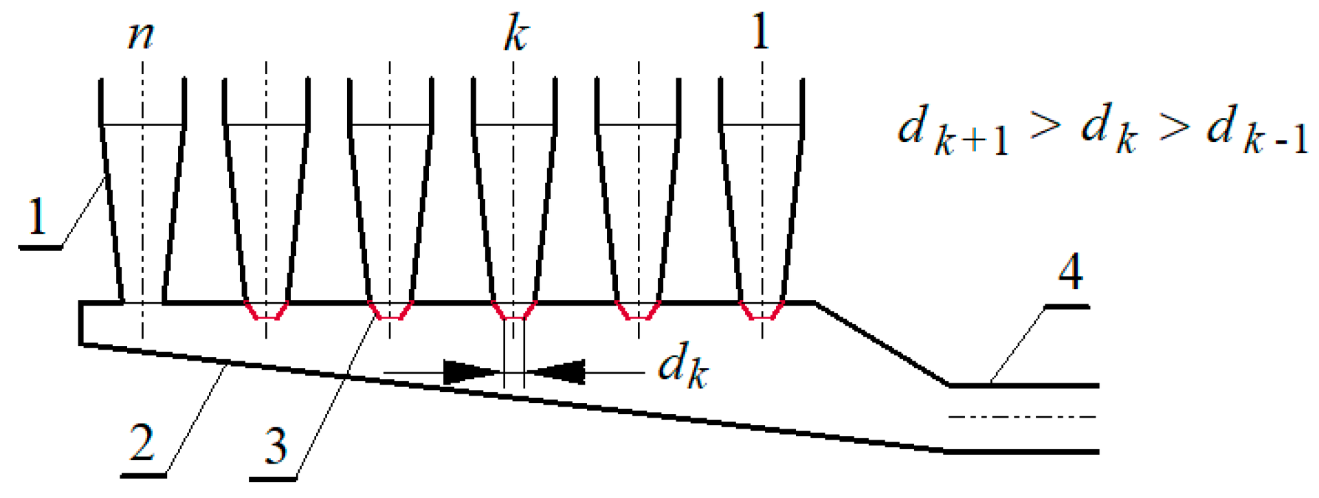
Yet another method aimed at achieving even suction may be the use of appropriately selected throttling elements (conical adapters) for the suction stream flow, mounted directly on the outlets of the cyclone suction stream—depicted in
Figure 9.
By changing aerodynamic resistance with its help, it is possible to regulate the size of the suction stream of the cyclone. The cap diameter must be selected depending on the position of a single cyclone in relation to the suction nozzle so that the same suction jets are obtained in all cyclones.
On the cyclones proceeding from the last to the first, caps of decreasing diameter are placed, and dk is introducing an increasing level of throttling of the suction stream. It should be noted that the cap’s dimension selection can be very laborious, as it requires many consecutive analytical calculations alternating with their experimental verification. As can be seen, this method is suitable for use in filters with a small number of cyclones and settling tanks of any size and shape.
Specific method choice and method used depends not only on their efficiency, but also on the form of the multi-cyclone and the spatial limitations at the place of its installation, as well as on the possibility of carrying out an appropriate scope of tests. It is very likely that the combined use of two or more of these structural measures will be the most effective.
Figure 10 shows an example of a combined method used to obtain a relative uniformity of the suction streams from individual cyclones in the multi-cyclone. The multi-cyclone cyclones are distributed over the circuits of four coaxial circles. The axial-symmetric sedimentation tank has one central suction port. Within a group of cyclones arranged in a given circle, their position is approximately the same in relation to the pipe stub, but different in each group. Between the outer and inner walls of the settling tank there is a partition, due to which two annular channels are formed—the outer and the inner one—which carry away the suction streams from the two pairs of cyclone units. In the partition wall, above the inlet of the suction connector, there is an opening for removing the suction stream from the internal channel.
To equalize streams, throttle caps can be placed on the cyclone outlets from the inner circle. It is a relatively easy procedure as all the caps will be the same due to the symmetry. The suction stream values from the external and internal channels must be proportional to the number of cyclones they “serve”. This requirement can be met by placing an appropriately selected orifice in the opening.
The advantage of the described multi-cyclone concept is the use of the cyclone-mounting plate surface, with their number of the order—one hundred or more—and small settling tank height, i.e., the relatively small dust collector dimensions.
2.2. Dust Extraction System Concept from a Multi-Cyclone
The decision was made to design a dust extraction system from the multi-cyclone dust collector on the basis of a two-stage filter (multi-cyclone-partition) from a T72 vehicle. The choice of this multi-cyclone for testing is supported by the fact that it is used in heavily-used vehicles, and thus it is possible to verify how the design was carried out experimentally. To facilitate the analysis of the results, the tested multi-cyclone was designated MT.
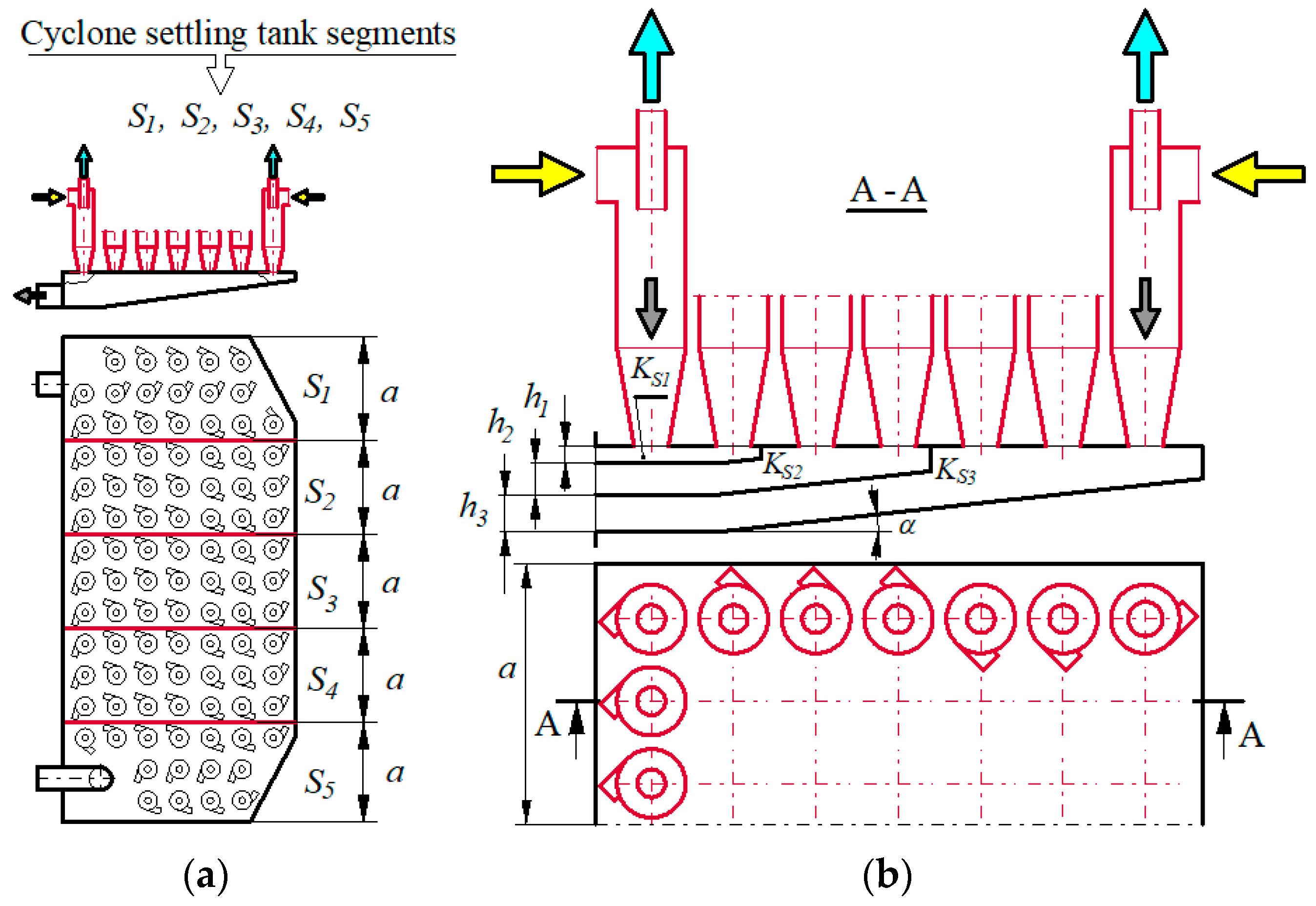
To ensure streams uniform suction from individual MT multi-cyclone cyclones, the most appropriate method seems to be to change the internal structure of the multi-cyclone dust settler by dividing the dust settler space into segments with vertical partitions. The segment space should be divided by horizontal shelves into independent and isolated suction channels, to which specific groups of individual cyclones should be assigned.
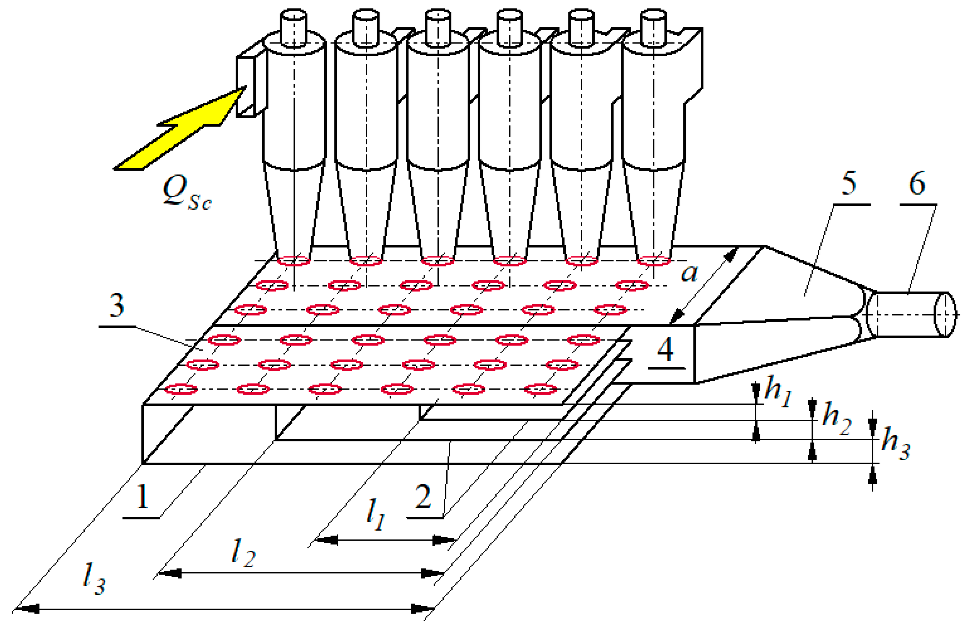
Figure 11 shows the idea of dividing the MT multi-cyclone dust settler into segments, and then the segments into suction channels.
Dust settling chamber of the MT multi-cyclone is divided into widths with vertical internal walls (partitions) in five equal and independent parts (S segments) with a width of a. Each segment (module) includes three columns of cyclones (seven cyclones in a column). The chambers of the segment settlers were divided by horizontal (parallel to each other) partitions into three separate suction channels (KS1, KS2, KS3) with different heights h1, h2, h3. A segment may include a different number of suction channels, and a different number of cyclones may be assigned to each channel.
The basic problem when dividing the segment settling chamber into suction channels is the setting of horizontal partitions at appropriate heights h1, h2, … hi. The channel heights of the dust settler segment should be determined by calculation, and then verified experimentally during the tests of the actual segment in dust settler.
2.3. Dust Settler Model Tests
2.3.1. Model Research Purpose and Subject
The research aim was to determine the height of the suction channels formed by the horizontal partitions in the segment’s dust settling chamber. The subject of the research was a model of the segment from MT multi-cyclone dust settler, including 18 cyclones arranged in three identical columns.
2.3.2. Dust Collector Segment Model
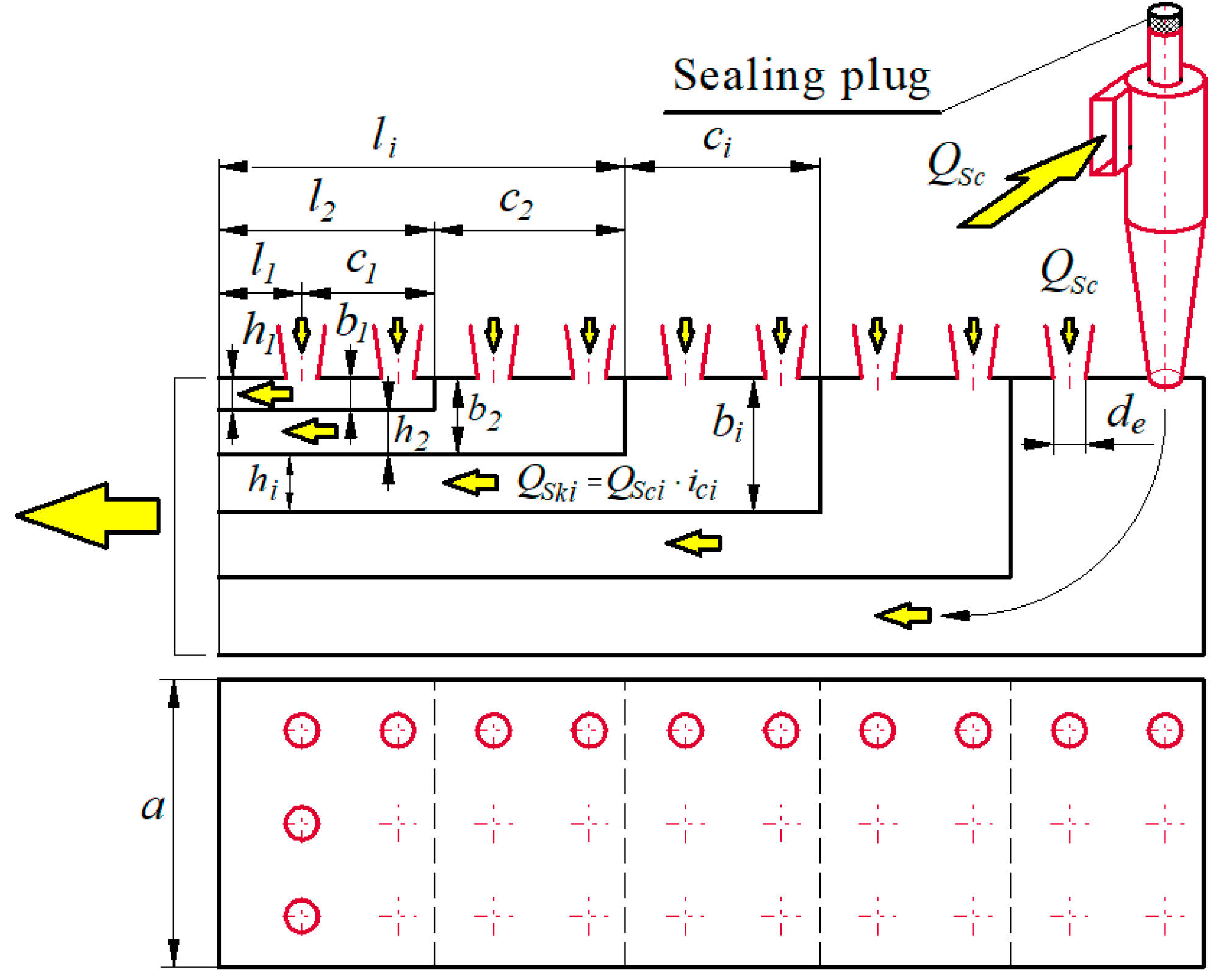
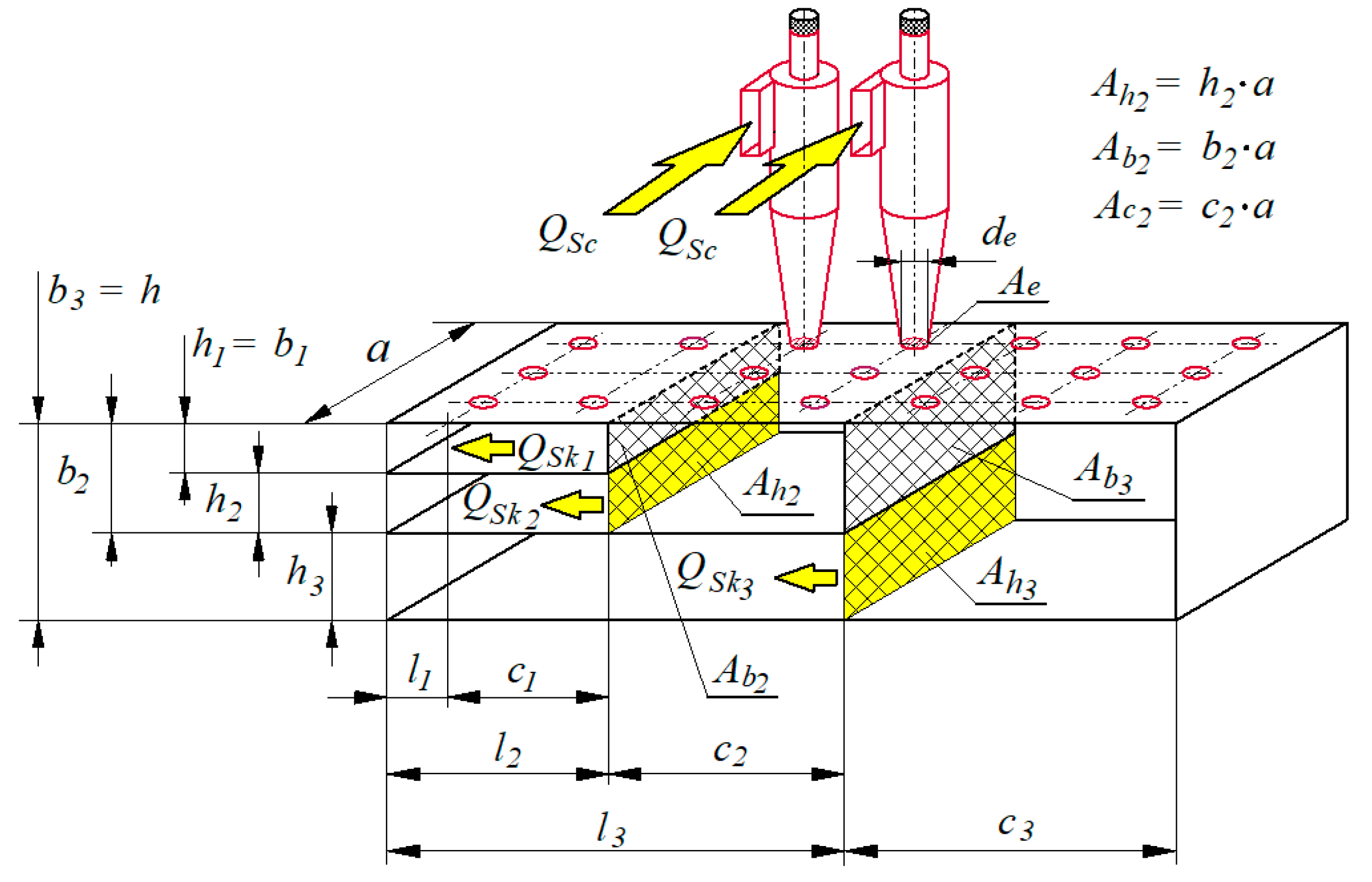
The schematic segment diagram in the motor vehicle air filter multi-cyclone settling tank (
Figure 12) can be used for the calculation of different settling tanks, but with the same construction principle, i.e., with a division into segments and suction channels.
The following assumptions were made during the calculations:
the suction channels should be numbered in sequence from the cyclone mounting plate;
the relevant channel walls are parallel to each other;
channel No.1 sucks air from six cyclones arranged in the first two rows, channel No. 2 sucks air from six cyclones from the next two rows, and channel No. 3 is assigned the last three rows of cyclones—depicted in
Figure 12;
the suction channel is divided into a chamber of length ci and an exhaust channel of length li, where i stands for the sequence number of the channel;
the boundary of the chamber division and the inlet channel is the plane where the chamber space ends with a cross-sectional step in the flow direction from the chamber height bi to the height of the channel hi;
in channel one, due to the lack of a step (the height of the channel and the chamber is the same
h1 = b1), the cross-section of the suction channel in axis plane of the first-order cyclones was assumed as a chamber border and outlet channel—depicted in
Figure 12;
all cyclones are the same, and the diameter of the cyclone dust extraction (suction) opening is de.
The calculations are based on a simplification in relation to the real object of the dust settler segment—fragments inclination to the lower segment walls has not been taken into account (
Figure 11b). Therefore, the dust collector is a low-height, rectangular cassette. As a result, the segment chamber has a different volume than in the real system, and the channel is rectilinear. In the case of inflow of an air stream from the cyclones (diameter
de) to the chamber, a value change of the cross-sectional area of the flow has a major influence on the pressure loss. The cases cited in the literature consider, first of all, the value change of the flow cross-sectional area, regardless of the chamber shape and volume [
44,
45]. Thus, replacing the actual form of the chamber with a cuboid does not introduce a significant error. The assumption of a rectilinear channel (omitting the flow direction change in the channel) is justified because this change is very gentle, and, in the outlet channel of the first suction channel, the flow direction does not change at all. The small angle of the lower walls’ inclination (
α = 6°) allows for the same height of the channel along its entire length. With such a slight deviation in the flow direction, pressure losses are negligible. If the chamber height and the duct in the first segment are the same, there is no pressure loss in that segment due to air outflow from the chamber into the duct.
Due to the low flow velocities occurring in the suction channels (below 4 m/s) and very small relative pressure drops in relation to the environment, the air density value in each case can be assumed to be the same—equal to surrounding air density.
The air flows directly into each suction channel chamber from the cyclones with suction openings with a diameter of
de and an air stream (with separated dust particles) of size:
where:
QSci—air stream sucked from a single cyclone,
i-th suction channel, and
ici—number of cyclones covered by the suction channel.
Air flow
QSc suctioned from a single cyclone is determined by:
where:
QG—filter outlet air stream,
m0—suction level,
icm—cyclone number in the multi-cyclone.
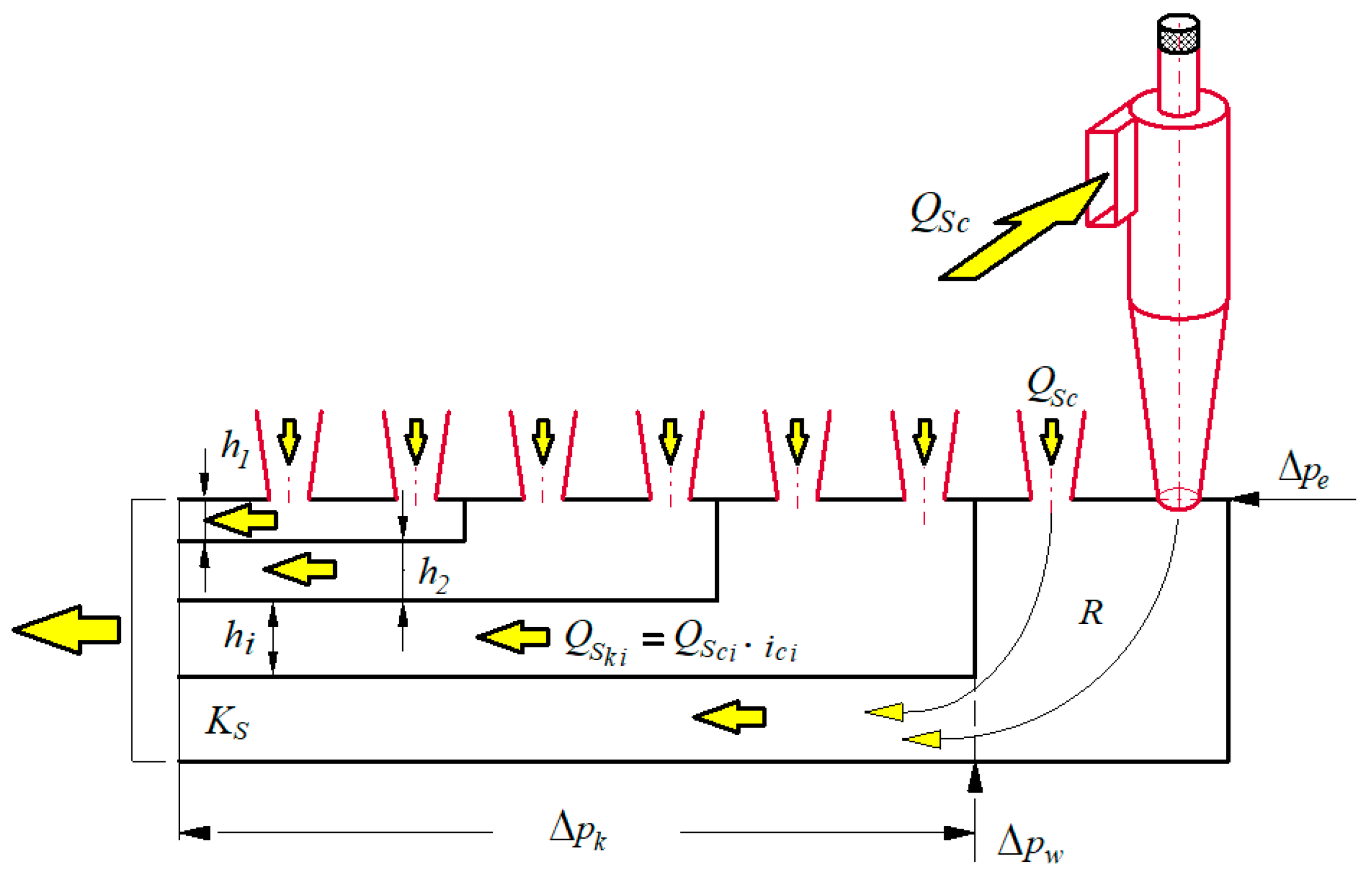
Main issue in settling tank flow calculations is to determine the pressure losses in the suction channels of the settling tank segment. Calculations considered two main causes of pressure losses occurring in the real object—i.e., the suction channel. These are the swirls of the air stream that occur from sudden changes in the flow channel cross-section and the air friction against the channel walls.
During air stream flow through the suction channel from the dust settling tank segment, three types of pressure losses were assumed—depicted in
Figure 13:
Δpe—local pressure loss occurring with QSc streams inflow from the cyclones to the segment chamber, resulting from a sudden increase in the channel cross-section. The air from the cyclones enters the duct chamber through circular openings with a diameter de in the upper wall of the chamber and fills the chamber’s cuboidal space. This results in a local pressure loss due to the reduction of the jet velocity and streams mixing.
Δpw—local flow QSk pressure loss flowing into the channel, wherein the inlet is located in the side chamber wall. The transverse dimensions of the outlet duct (inlet) are much smaller than the side wall dimensions of the chamber. In this case, it can be considered that there is a flow through the conduit with a sudden cross-sectional narrowing.
Δpk—pressure loss resulting from friction during stream flow through a channel with a constant cross-section.
The total pressure loss during the air flow through the
i-th suction channel is determined by:
The local pressure loss Δ
pei at the air stream
QSci inflow into the chamber of the
i-th channel can be represented by:
where:
ρ—air density,
ξe—pressure drop coefficient,
υe—air flow velocity to the suction channel chamber—air velocity in the outlet opening of the cyclone suction (bleed) stream with a diameter
de calculated from:
However, the pressure drop coefficient
ζe should be determined from:
where:
Ae–the cross-sectional area of suction stream outlet opening (diameter
de) from the cyclone,
Aci–chamber upper wall area (
Figure 14), in which the cyclones are attached, calculated from:
The local pressure loss during the suction stream flow
QSki through the rectangular channel opening with dimensions
a and
hi (
Figure 11) is represented by:
where:
υki—air velocity in the duct of height
hi and width
a,
ξwi—pressure drop coefficient, depending on the ratio of the transverse area of the outlet duct opening
Ahi to the area of chamber front wall
Abi [
44]:
The air velocity in a duct of height
hi and width
a should be calculated from:
The pressure loss in the outlet channel is captured by:
where:
λki—duct pressure loss coefficient,
li—duct length,
dri—equivalent duct diameter.
To calculate the coefficient
λki the Mises formula was used, which makes its value dependent on the channel transverse dimensions, flow type, and material roughness from which the channel walls are made [
45]:
where:
kR—coefficient characterizing channel walls roughness,
Reki—Reynolds number defined by:
where:
ν—air kinematic viscosity.
Due to the exhaust duct cross-section’s rectangular shape, its equivalent diameter
dr should be calculated according to:
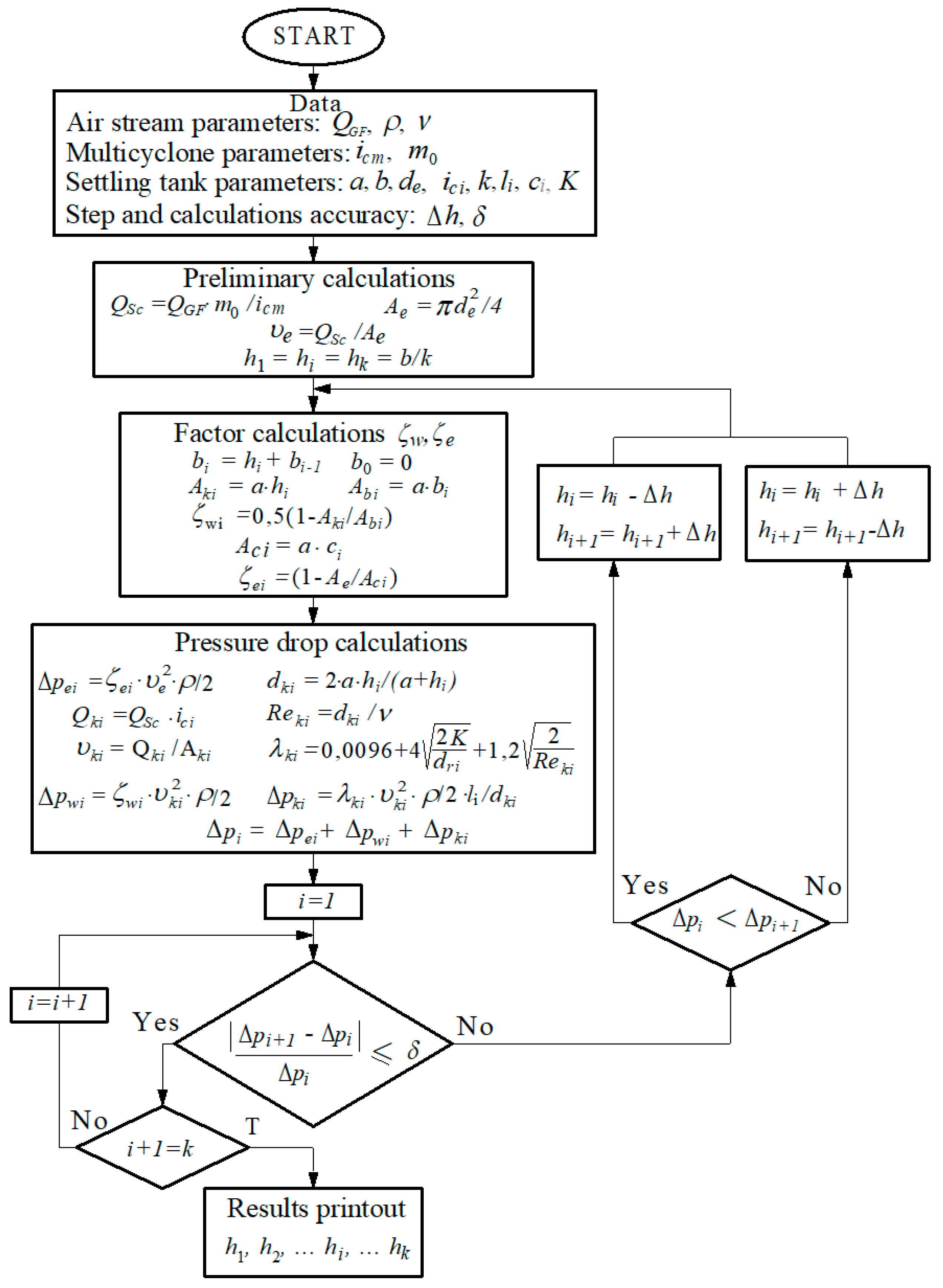
2.3.3. Model Research Methodology
Flow model tests consist of making total pressure losses calculations in each suction channel separately, assuming the initial assumption of the channel numbers
k and their equal heights
hi using:
The task is to calculate such heights
h1,
h2,
h3, …
hi and segmented suction channels (with a constant segment width
a and a constant height
h of the settling chamber), so that the total pressure losses in the suction channels on the section between the outlets from the cyclones and the outlet from the channel suction were equal to:
The calculations were made using the successive approximations method, a calculation program specially designed for this purpose—depicted in
Figure 15.
Table 1 presents data for the numerical calculations, including the parameters of the air stream, MT multi-cyclone, and segmented dust trap.
The numerical calculation results, including the channel’s height at the segment outlet in the MT multi-cyclone dust settler, are presented in
Table 2.
Obtained channel heights hi at dust multi-cyclone segment outlet MT have the following values: h1 = 12 mm, h2 = 19 mm, h3 = 26 mm.
The dimensions that were determined in this way were used to construct the dust settling tank segment intended for further (experimental) flow tests—depicted in
Figure 16.
2.4. Dust Settler Segment Experimental Tests of Air Filter Multicyclone
2.4.1. Purpose and Subject of Flow Tests in Dust Settler
The aim of the experimental flow tests was to evaluate the proposed changes concept in the internal structure of the air filter multi-cyclone MT dust settling tank segment due to the improvement in uniformity of suction from the individual cyclones, which should positively affect the separation efficiency of the entire multi-cyclone.
Research subject was dust settler segment of the MT multi-cyclone air filters built on the basis of the model test results of the dust settler. A schematic structure diagram of the MT multi-cyclone composed of the segments is shown in
Figure 13.
In the inertial filters, made of several dozen cyclones, it is possible to use various methods for organizing the ejection suction. The choice of a specific method and the method used, aimed at ensuring the suction streams have the same values for all individual cyclones, depends not only on their efficiency, but also on the form of the multi-cyclone, number of cyclones and dust separator configuration, space limitations in the place of its installation, and the possibility of carrying out an appropriate research range.
The uniform value of the suction streams from the individual cyclones can be ensured by using the equal resistances method of suction streams through appropriate structural changes to the multi-cyclone dust settler, which consists of dividing the settling space into independent segments and channels covering a specific number of cyclones.
The calculation algorithm developed by the author enables the initial selection of the height at the outlet h1, h2, …. hi and subsequent suction channels for the dust settling tank segment, in terms of equal resistance to the air flow streams through the channels. The final selection of the number and height of h1, h2, …. hi and the channels should be made during the experimental tests of the multi-cyclone separate segment.
The algorithm for calculating the segment of multi-cyclone settling tank in a motor vehicle air filter can be applied to the calculation of the different settling tanks, but with the same construction principle—i.e., with a division into the segments and suction channels. A segment may contain a different number of suction channels, and each may be assigned a different number of cyclones.
Multi-cyclone structure made of segments significantly facilitates the design process and allows to give it the most convenient shape. The number of segments in a multi-cyclone can be easily adapted to the needs of the engine properties. Basic research is then confined to a segment, making it much simpler and less costly. The tests of the multi-cyclone, as a whole, usually concern the possible corrections of the arrangement and shape of the suction pipes and the method of their connection with the suction stream collector. The segmented (modular) design of the multi-cyclone gives the possibility of versatility by “assembling” the multi-cyclone from the number of modules resulting from the air consumption of the engine, e.g., one segment for every 300 m3/h or one segment for 50 kW of engine power.
2.4.2. Flow Research Methodology
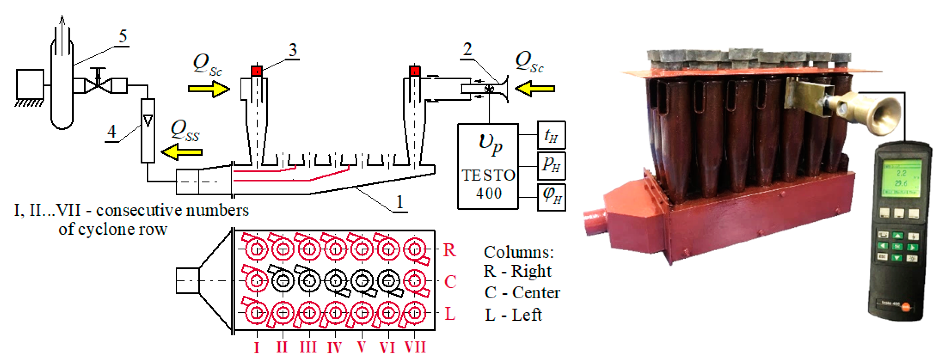
Tests were carried out in a laboratory, reproducing the work of inertial filters in the real conditions of a vehicle user. QSc values of suction streams from the individual cyclones of the dust settling tank segment were measured, in which the internal structure of the settling tank was changed by dividing it into suction channels. On this basis, an assessment was made for the improvement of suction uniformity, which was caused by the division of the multi-cyclone dust settling chamber into segments and the division of the settling chamber into suction channels. Research course and subsequent design changes of the dust collector are presented, marking them successively A, B, C, and D for the MT multi-cyclone segment, until a satisfactory suction uniformity is obtained.
The flow tests of the MT multi-cyclone dust settler segment were carried out in two stages at the stand, the diagram of which is shown in
Figure 17. Tests were carried out according to the methodology used to measure the suction stream values from the single cyclones of a complete multi-cyclone. During the tests of the MT multi-cyclone segment, suction stream values from the left (L) and right (R) cyclones of the segment, as well as from the first (I) and last (VII) cyclone rows, were measured (
Figure 17).
From the segment dust collector, the
QSs suction stream, being the sum of
QSc suction streams from the individual cyclones.
where: I, II, II, …
j….
J—consecutive cyclone number in the column.
The main suction stream
QSs from the settling tank of the multi-cyclone segment was determined from:
where:
mS—number of segments into which the multi-cyclone dust collector has been divided,
QS—suction stream from the multi-cyclone settler, determined for the rotational speed
nN of the engine and the extraction rate
m0 = 4, 8,
i 16%.
In the first stage, the values of the QSc suction streams from the individual cyclones of the selected rows and columns of the segment with a dust trap in the original version were determined. In the second stage, the values of the QSc suction streams were measured from the same individual cyclones of the segment in which the internal structure of the dust settling chamber was changed. The settling chamber was then divided into suction channels with heights h1, h2, h3 … hi resulting from the model calculations and with the appropriate, and previously established, assignment of the cyclones. At this stage, several variations for dividing the segment’s settling chamber into suction channels were investigated.
The initial variant (variant A) of the MT multi-cyclone segment is a dust collector, the chamber of which is divided into three suction channels with heights at the outlet: h1 = 12 mm, h2 = 19 mm, and h3 = 26 mm.
2.4.3. Test Results Analysis of MT Multi-Cyclone Segment
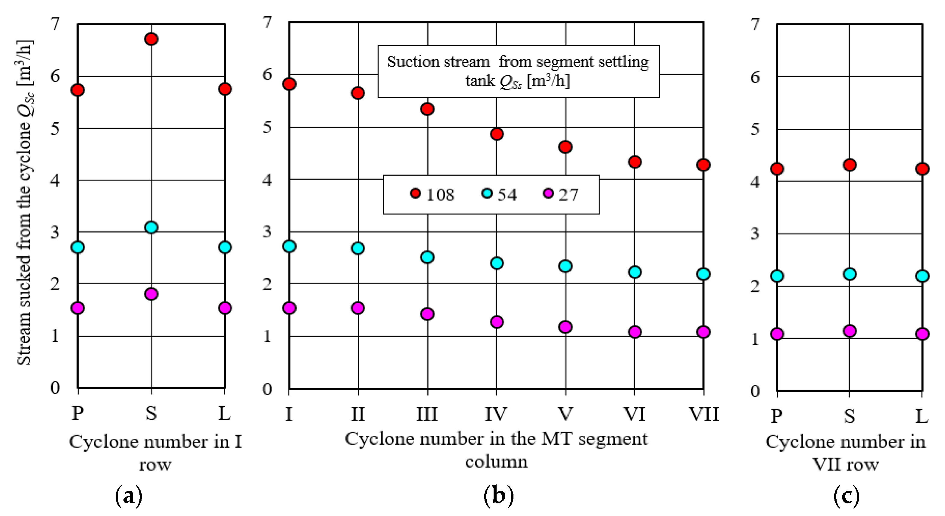
Suction stream values from the left (L) and right (R) cyclones of the MT multi-cyclone segment for the same rows of cyclones differ slightly, and therefore, the measurement results of the suction streams from the cyclones from only one, the left column (L) of the multi-cyclone segment, were used for further analysis (
Figure 18). The highest values of the
QSc suction streams from the individual cyclones of the segment with a dust settling chamber in the original version (before the division of the settling chamber into channels) were recorded, regardless of the value of the total
QSs suction stream, for the first cyclone from the middle column (S).
Segment dust collector chamber structure change (variant A) with the division into three suction channels (
Figure 19) resulted in a significant improvement in the suction uniformity. There was a decrease by about 13% of flow values sucked off
QSc from the first two cyclones (channel 1) and a significant increase by 16% of the flows in the channel No. 3. In channel No. 1 there were large (about 14%) differences between stream values sucked off from cyclone No. I and No. II. In the remaining channels, these differences do not exceed 4%. The stream sucked off from cyclone No. II with its small value
QSc = 4.6 m
3/h clearly differs from the suction streams from the remaining cyclones of the segment, the value of which fluctuates within the range of 5.2–5.4 m
3/h.
The reason for such a low value of the QSc flux when suctioned from the second cyclone may be the small height (12 mm) of channel No. 1, and the lack of a chamber into which the suction streams from the cyclones flow, as is the case with the other channels, as well as the large distance of the second-order cyclones from the outlet stub, which suppressed the air flow QSc. The above analysis shows that channel 1 should not be assigned a larger number of cyclones. In the case of the tested settler, it should only be the first row of cyclones.
Variant B of the dust settler has a three-channel structure for the dust settling chamber, but with a different assignment of cyclones—depicted in
Figure 19. Due to this structure, values of the suction streams
QSc from channel No. 1, and the first cyclones of each of the remaining channels, assume the same—and at the same maximum time values. In channel No. 2 and No. 3, it can be observed that as the position of subsequent cyclones moves away from the rear wall of channel No. 1, the values of the
QSc suction streams systematically decrease. The suction stream from the last cyclone in channel 2 is 13% lower, and the suction stream from the last cyclone in channel 3 is 9% lower than the others. The reason for such a low value of the flows
QSc when suctioned from the last cyclones may be the oblique channel bottom shape, which reduces the chamber volume into which the flows can be suctioned from the cyclone’s flow, which suppresses the outflow of the air stream
QSc. The test results of variant B of the dust settler suggest that assigning more than two cyclone rows to the channel is not recommended. At the same time, assigning a smaller number of cyclones to one channel forces the division of the settling chamber into a larger number of channels, which complicates the design and increases the production cost.
Table 3 presents a summary of the changes in the height of the dust trap channels during the variant tests, and the number of cyclones assigned to the individual channels.
This problem was analyzed by examining variant C of the segment dust collector—depicted in
Figure 19. The structure of the segmented dust collector chamber (variant C) resulted from the division of this chamber into four suction channels with heights:
h1C = 8 mm
, h2C = 12 mm,
h3C = 16 mm, and
h4C = 21 mm with appropriate cyclone assignments—depicted in
Figure 16. The shape of the settling tank has been changed in relation to the original. The bottom of the settling tank and the subsequent partitions are parallel along their entire length to the upper cyclone mounting plate.
As a result of the introduced changes, a significant reduction in the differences between the values of the suction flows
QSc from the individual cyclones of the segment was achieved—
Figure 19. The suction streams from cyclones No. II and III of channel No. 2 have significantly lower (cyclone No. III by more than 8%) values than the suction streams from cyclones covered by channels No. 3 and No. 4, although the distance of these cyclones from the outlet of the channels (section A-A) is much greater.
The analysis of the structure of the designed settling tank (variant C) shows that both the volume of the chambers of channels 3 and 4 and the height b3 and b4 of these chambers (the distance between the outlet openings from the cyclones and the bottom of the chamber) are two and three times larger than the volume of channel chamber No. 2 and its amount b2, respectively. Thus, the attenuation of the streams outflow from the cyclones of channels No. 3 and No. 4 is much lower, which can be seen in the form of higher values of the suction streams. The highest values have the suction streams from the cyclones of channel No. 4. The results of the research and the above analysis suggest changes in the structure of the settling chamber within channels No. 2 and No. 4.
Variant D of the chamber of the settling tank, in relation to variant C, has a similar height to channel 2, but higher by 1 mm, and is similar to the height of channel 4, but lower by the same value.
The measurement results of the suction flow values
QSc from the individual cyclones for the left column (L) of the segment (variant D) of the dust settling chamber, for two values of the suction flow
QSs = 108 m
3/h and
QSs = 54 m
3/h, show (
Figure 19) a clear improvement in the uniformity of the suction between cyclones in the channels, and within the entire column. The differences between the suction streams from adjacent cyclones in channels 3 and 4 do not exceed 3%. For a lower value of the suction stream (
QSs = 54 m
3/h), these differences are insignificant.
2.5. Separation Efficiency Experimental Studies of Single Cyclones in the Multi-Cyclone Segment
2.5.1. Purpose and Scope of Research
The efficiency research for dust removal from the cyclones in the SMT segment of the MT multi-cyclone was aimed at experimentally verifying the developed concept of the changes that can be made in the design of the internal structure of the dust settling chamber of the segment. An experimental evaluation of the developed concept of the changes that can be made in the internal structure of the dust settling chamber of the SMT segment of the MT multi-cyclone was performed due to the efficiency of dust removal in individual cyclones. The separation efficiency values of single cyclones from the left column (L) of the SMT segment were determined. The research was carried out in two stages:
stage I—dust removal efficiency measurements from the cyclones of the segment with the original dust trap;
stage II—dust removal efficiency measurements from the segment cyclones after making changes to the internal structure of the dust collector chamber according to variant D;
2.5.2. Research Methodology and Conditions
The dust removal efficiency tests for single cyclones of the
SMT segment were carried out on the stand, the diagram of which is shown in
Figure 20. The tested segment, being the fifth part of the MT multi-cyclone, includes 21 D-40 cyclones arranged in seven rows and three columns in the same way as in the original multi-cyclone. In the first stage of research, the segment settling chamber has the shape of a multi-cyclone settling chamber. On the other hand, in stage II of the tests, the sedimentation tank is divided into four suction channels—as is shown in variant D. Directly at the outlet of the segment’s sedimentation tank, in the suction line, there is a safety filter that stops the dust separated by the cyclones. The cyclone outlet nozzles of the segment (purified air) are connected by a common chamber, in which there is a measuring filter cartridge designed to retain the
mZA dust mass carried along with the exhaust air from the cyclones.
The test dust was dosed to the inlet stub of the tested cyclone, which ended with a dust chamber where it was mixed with the inlet air stream Q0. The separation efficiency was determined successively for the extreme single cyclones (No. I, II, … VII) of the left column (L) of the multi-cyclone segment under the following conditions:
air outlet stream from a single cyclone QGc = 34 m3/h, resulting from the number of cyclones used in the filter multi-cyclone and the air demand at the rotational speed nN = 2000 obr/min in vehicle engine;
air stream suctioned from a single cyclone QSc = 2.72 m3/h for the degree of the ejection dust extraction from the settling tank m0 = 8%;
dust concentration in the air s = 1 g/m3;
measurement time—time of uniform dust dosing to the cyclone tpom = 3 min;
PTC-D test dust, being a domestic replacement for AC-fine dust.
For each cyclone from the right column, starting from cyclone No. I up to cyclone No. VII, j = 5 for the separation efficiency measurements φc, which were performed successively according to the following methodology:
the mass of the dust dispenser container and the were determined, before each measurement;
suction fans for the main and suction pipes were started, and then, on the basis of the indications from the U-tube water pressure gauges and the gauge diagrams of the measuring orifices, the required value of the air streams
QGs and
QSc was determined—depicted in
Figure 18;
dust was evenly dosed to the set cyclone during time tpom;
air streams flow QGs and QSc were closed, and then the mass of the dust dispenser container and the mass of the measuring filter cartridge after the measurement were determined;
dust mass loss from the dispenser was determined, and thus the dust mass introduced with the air stream into the cyclone according to the formula:
After cycle j = 5, the efficiency measurements for a given cyclone were performed and the average value of the separation efficiency and dust concentration of inlet air to the cyclone were calculated.
2.5.3. Reasearch Results Analysis
The test results of the separation efficiency values for single cyclones from the left (L) column in the
SMT segment of the MT multi-cyclone are shown in
Figure 21.
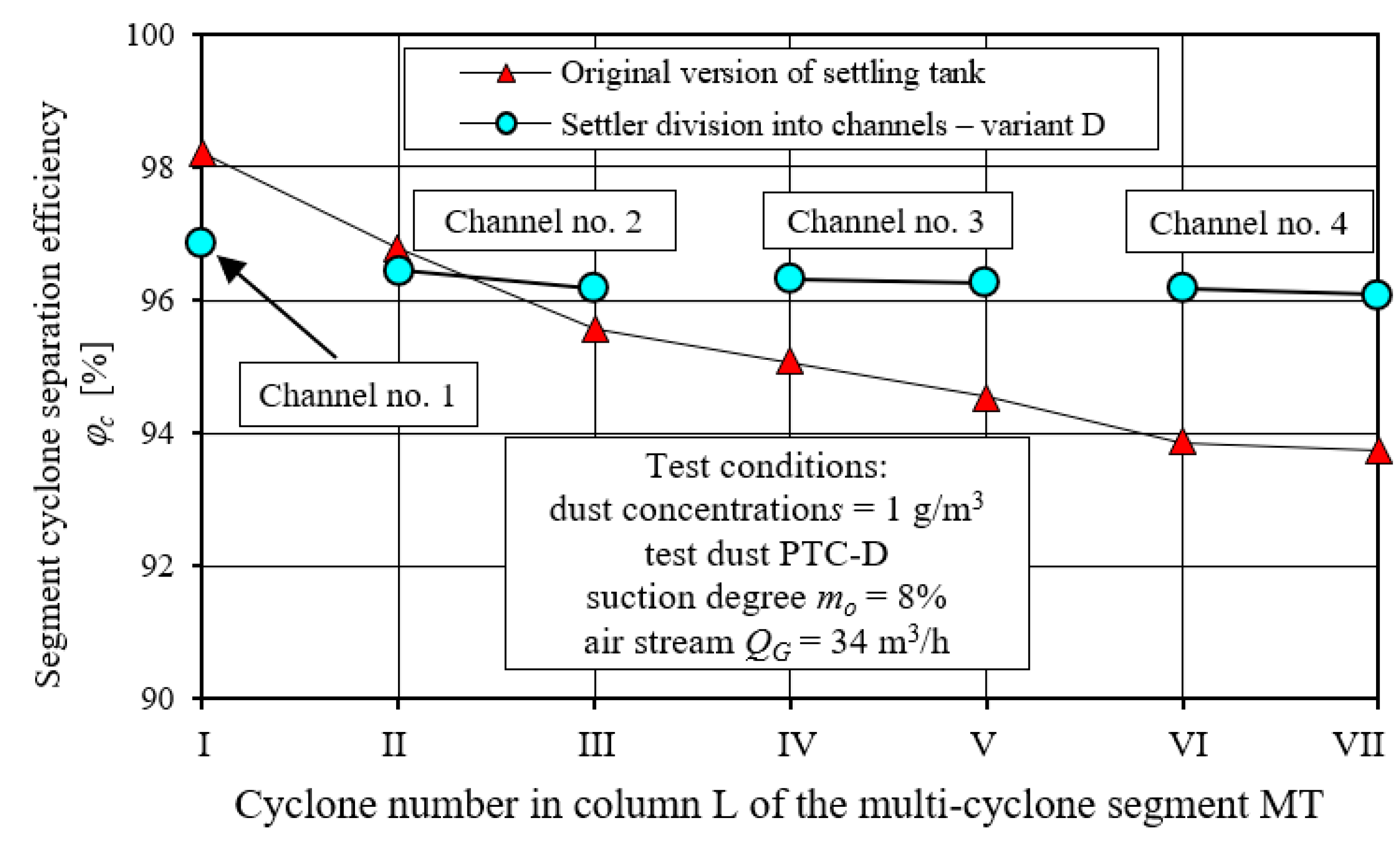
As the cyclone’s position moves away from the suction nozzle, the cyclone separation efficiency values of the segment, whose settling chamber is a common part for all cyclones, are decreasing. For the first (I) cyclone, a separation efficiency of 98.2% was recorded in the column, and for the last (VII), a separation efficiency of 93.7%. There was a 5% difference in cyclone separation efficiency, which results is mainly caused by the decreasing values of the suction streams (suction rates) from these cyclones—as demonstrated by the flow tests of the multi-cyclone and its dust settling device. A decrease in the cyclone separation efficiency may also be caused by the interaction of the swirled streams flowing out of the cyclones and flowing into the common chamber of the dust settling chamber, and can even lead to the possibility of reverse flows in the cyclones located on the periphery of the multi-cyclone.
The separation efficiency values for the same cyclones in the segment in which the dust settling chamber structure was changed (the chamber was divided into suction channels) show much smaller differences, although a slight decrease in the cyclone efficiency is noticeable with their location being further from the suction connector—depicted in
Figure 21. The efficiency separation values from cyclone No. I, from which dust is suctioned through channel No. 1, is clearly higher than the efficiency of the other cyclones in the column and has a value of 96.8%. The cyclone separation efficiency, from which suction takes place through the separate channels 2, 3 and 4, is slightly lower and ranges from 96.1–96.4%. After changing the structure of the dust settling chamber, the separation efficiency of the first two cyclones (I and II) decreased, while the remaining cyclones achieved higher efficiency values, with the highest increase (about 3%) recorded for the last (VII) cyclone in the column.
A slight decrease in the cyclone separation efficiency of the tested dust settling column with a chamber structure that guarantees even suction may be caused by the impact of the main (purified air) QG streams flowing from the cyclones in the chamber area, where the measuring filter insert is located. The different distances of the cyclone outlet pipes from the segment of the main stream outlet can cause different pressure drops for these streams (the further the cyclone is located, the greater the pressure drop) in the cyclone in the outlet stub pipe section, and for the individual cyclones. The air stream exiting the cyclone furthest from the main stream outlet port may be less than the value of the air stream exiting the cyclone directly at the outlet port. The lower value of the air stream means a lower speed and, at the same time, a lower inertial force, and thus the cyclone obtains efficient dust removal at a lower level.


