Article

Power Distribution Control Framework for Renewable Energy Architecture with Battery-Supercapacitor Based Hybrid Energy Storage Systems

College of Electrical Engineering, Zhejiang University, Hangzhou 310027, China
*
Authors to whom correspondence should be addressed.
Energies 2021, 14(24), 8312; https://doi.org/10.3390/en14248312
Submission received: 12 October 2021 / Revised: 22 November 2021 / Accepted: 1 December 2021 / Published: 10 December 2021

Abstract

:
Due to the intermittence and randomness of the renewable energy, hybrid energy storage system is widely adopted to suppress the power fluctuation. Power distribution is crucial for the robust and efficient operation of hybrid energy system. This paper proposes an innovative framework for hybrid energy storage system power distribution combining main circuit topology, modulation method and power distribution strategy. Firstly, hybrid modulation strategy to realize power distribution in a single-phase inverter is introduced. Then, power load prediction and low frequency filter are utilized to generate references for power distribution. Finally, the simulation model is established to test the framework and the result demonstrates the superiority of the proposed framework. The mean absolute percent error of the proposed SSA-LSTM mdoel is 0.0955 and the prediciton error by 40% compared with conventional LSTM model. Additionally, the energy management framework can adjust the port power distribution ratio flexibily to significantly suppress the power fluctuation of the grid and the operation cost of the hybrid energy storage system by reducing the charge and discharge cycle of the battery.

1. Introduction

Under the dual pressure of excessive fossil energy consumption and environmental degradation, the renewable energy systems with distributed generator (DG) such as solar photovoltaic (PV) and wind turbine (WT) have aroused wide attention in the recent years [1]. Without pollution, the renewable energy systems will play an essiential part in the modern power system. However, there exist some concerns about the development of renewable energy systems due to their intermittent and random features [2]. The generated energy of DG is subject to environmental factor like solar irradiance, temperature and weather [3], which poses threat to the stability of the main grid. To deal with this problem, the large scale distributed energy storage units are usually utilized to suppress the fluctuations in energy production and electric power load to improve the reliability and robustness of microgrids [4,5]. Conventional battery energy storage system (BESS) suffers from high capital cost and capacity attenuation due to frequent charge and discharge, which restricts the healthy and sustainable develop of renewable energy system [6,7]. As a remedy to that issue, hybrid energy storage system (HESS) with multiple types of energy storage devices is becoming mainstream.
Various energy storage devices are equivalent to DC ports with different characteristics in energy density and power density [8]. These storage devices can be generally divided into two types: high-energy storage (ESS-E) and high power storage (ESS-P) where ESS-E is responsible for long-term energy fluctuations [7,9] and ESS-P deals with the fast transient power [10]. Battery-Supercapacitor (SC) is the classical combination of ESS-E and ESS-P in many scenarios, making their respective advantages complementary to each other [11,12].
To realize flexibile power distribution between different ports of ESS and ac grid, the HESS consists of three vital parts, i.e., the power converter layer, the modulation layer and the control layer [13]. The power converter layer is responsible of power conversion between the different ports and ac grid. The modulation layer is responsible to generate gate drive signal for power switches. The control layer allocates the stochastic load power between ports according to their characteristics.
In the power converter layer, various converter configurations have been introduced in the literature. Conventionally, the distributed power is implemented to batteries and SCs through extra dc-dc converters [14,15]. Undesirably, part energy has to be processed twice, and the conversion efficiency is reduced as well [16]. Multi-port converters(mpc) with multiple energy storageinterfaces and an ac port have drawn wide attention in HESS because of many specific merits, including higher integration, reduced harmonic content of the output voltage and less cost compared with conventional solutions [17,18]. MPC integrates ess energy management and dc/ac power output. Hereby, there is one stage of power conversion from energy storage to the grid, leading to the lower cost and higher efficiency. Notwithstanding the above advantages brought by mpc, the main challenging issue is to control and distribute the power between the ports according to specific application requirements [19].
In the modulation layer, many researches have been conducted to deal with the power distribution in MPC. Reference [8] shows the modulation strategy of a MPC in EVs. By turn several switches off in a fundamental period, the MPC operates in a two-level mode to allocate power between different ports. But this modulation strategy is unable to applied in multilevel converter. In the literature [16,20], modified space vector pulse width modulation(SVPWM) is proposed based on a specific three-port three-phase converter. However, the proposed methods is difficult to generalize to other topologies and power distribution algorithm is not mentioned in these literature and these methods will bring about low frequency harmonic content and is difficult to generalize to other topologies.
In the control layer, the power flow distribution algorithm for HESS have been considered to be significant in many scenarios. The control strategies can be divided into two parts, i.e., rule-based(RB) control, and AI-based control [13]. The RB control is based on human expertise. A typical RB control is filter-based control. Reference [21] shows a novel discrete Fourier transform phase-locked loop method to allocate power between PV and segmented energy storages. The main drawback of this method is that cutoff frequencies of the filter is hard to determine [22]. Machine learning methods demonstrate ground-breaking performance in this issue. Reference [7] proposes a knowledge-based battery energy management for hybrid electric bus. Apart from the computational burden, criticism against the existing driving pattern recognition methods is that the data are mostly based on binary classification, which may cause loss of useful information. Additionally, the converter topology is not taken into consideration.
In this paper, a framework for power distribution of HESS is introduced as is shown in Figure 1. The proposed framework is composed of MPC topology, modulation method and power distribution strategy. The combination of battery and super capacitor is chosen as HESS units due to its high feasibility and low cost. Asymmetrical Cascaded H-Bridge (ACHB) is set as the topology of the MPC due to its modularity and scalability [23,24]. The power distribution strategy is responsible for allocating output power reference for battery and SC on the basis of frequency while the modulation method is responsible for generalizing the switch drive signals. The main contributions of this paper can be summarized as: (i) In the power convergence layer, The inverter implementation is taken into consideration to improve the overall operation performance. (ii) In the modulation layer, the proposed hybrid modulation strategy can allocate the power flexibly between different ports without give birth to low frequency harmonic content. (iii) In the control layer, the proposed prediction method is superior in accuracy by improving long-short-term memory (LSTM) with Sparrow Search Algorithm (SSA). The mean absolute percentage error of proposed SSA-LSTM model is 0.0955 and prediction error is reduced by 40% compared with conventional LSTM model.
This rest content is organized as follow: Section 2 demonstrates the hybrid modulation method for power flow control based on the ACHB converter. In Section 3, the proposed power distribution algorithm is elaborated in detail. Then the simulation results are presented to verify the feasibility of the framework in Section 4. At last, the conclusion is summarized in Section 5.

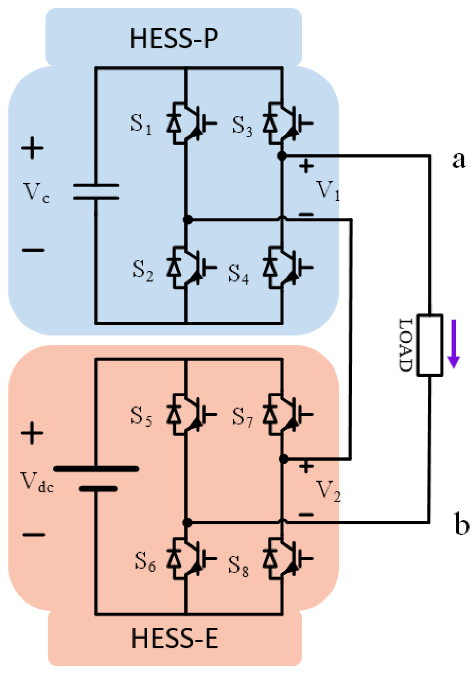
2. Asymmetrical Cascaded H-Bridge under Level-Shift PWM

ACHB is a typical multi-port single-phase converter for HESS because of its high modularity, which is shown in Figure 2. The main H-bridge module is connected to a battery pack V d c as a HESS-E and the auxiliary module is fed from a super capacitor V c as a HESS-P. The positive direction of output current is shown as well.
The relationship between output voltage levels and switching status can be described by switching function, which can be defined as:
S i ( t ) = 0 if switch is off 1 if switch is on , i = 1 , 2 , 3 , 4 , 5 , 6 , 7 , 8
where S i is the switch function of the switch i. Note that the switch pairs S 1 & S 3 , S 2 & S 4 , S 5 & S 7 and S 6 & S 8 work in a complementary mode, the relationship of complementary switches can be presented as the following:
S 2 = S 1 ¯ = 1 S 1 S 4 = S 3 ¯ = 1 S 3 S 6 = S 5 ¯ = 1 S 5 S 8 = S 7 ¯ = 1 S 7
The output voltage v a b ( t ) can be expressed by switching function:
v a b ( t ) = v 1 ( t ) + v 2 ( t ) = V c × ( S 3 S 1 ) + V d c × ( S 7 S 5 )
where v 1 ( t ) and v 2 ( t ) is the output voltage of main H-bridge and auxiliary cell. In order to analyze power distribution between ports, some assumptions are made, which are listed as
  • Dead-band intervals of switches are ignored.
  • The output current i o is an ideal sinusoidal wave, which can be expressed as i o ( t ) = I o m sin ω t + θ I , where θ I is the phase angle of output current.
  • The conduction voltage drop and equivalent resistance of switches are ignored.
  • The voltage increment of super capacitor and battery within a fundamental cycle is negligible.

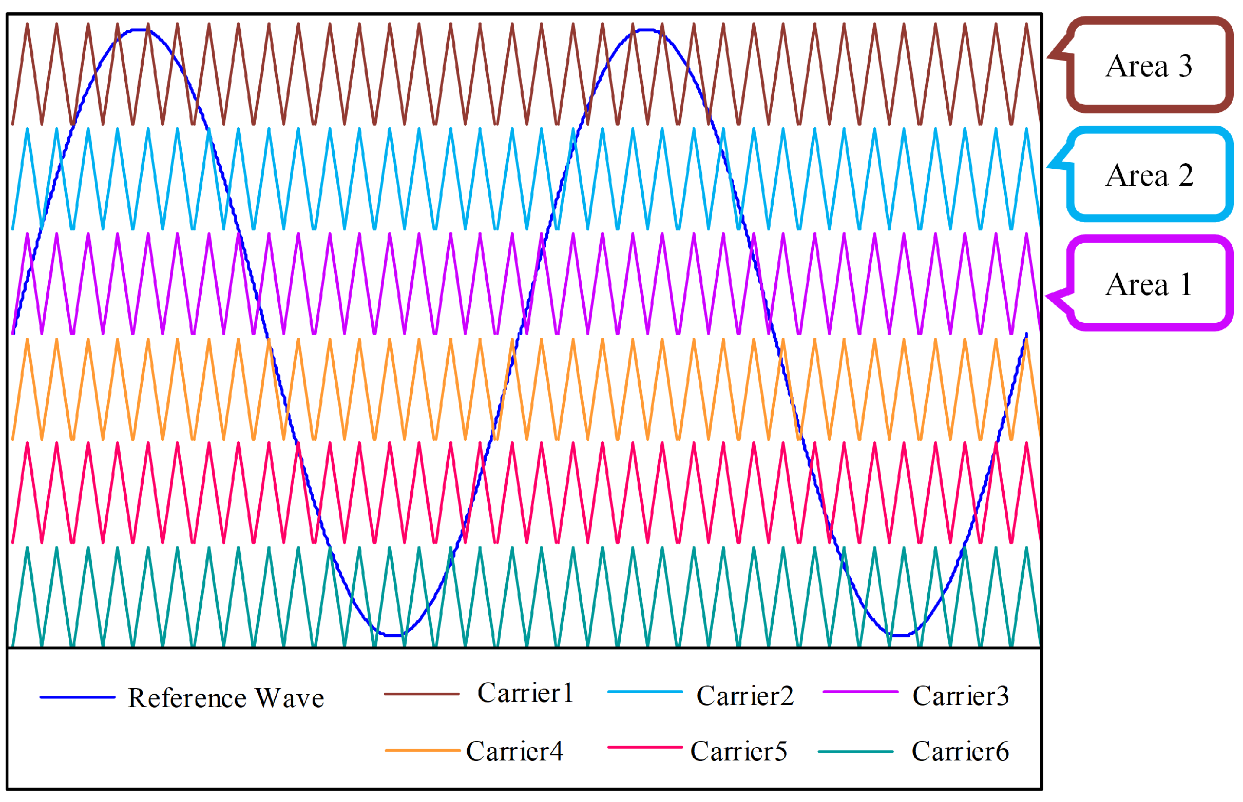
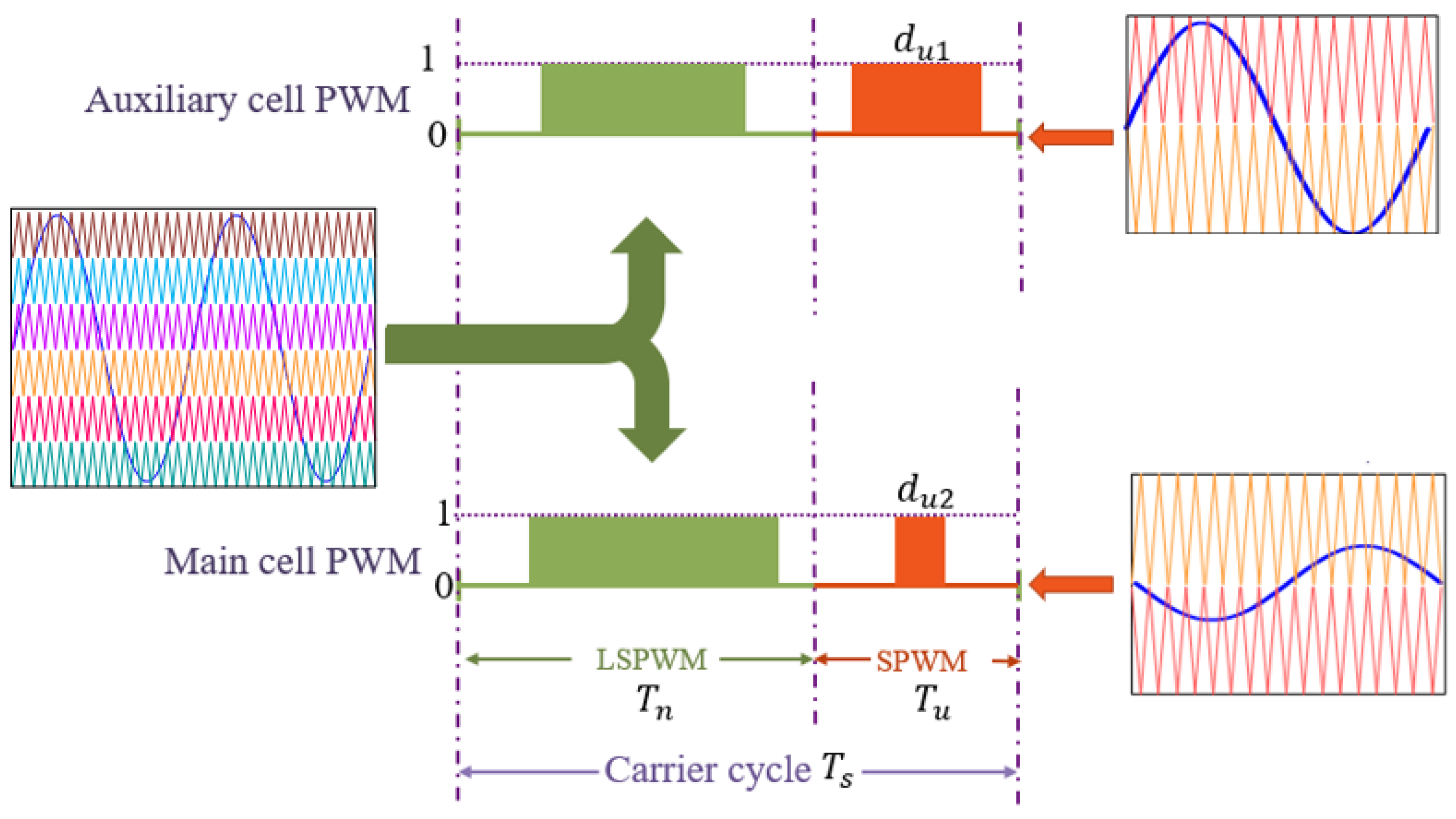
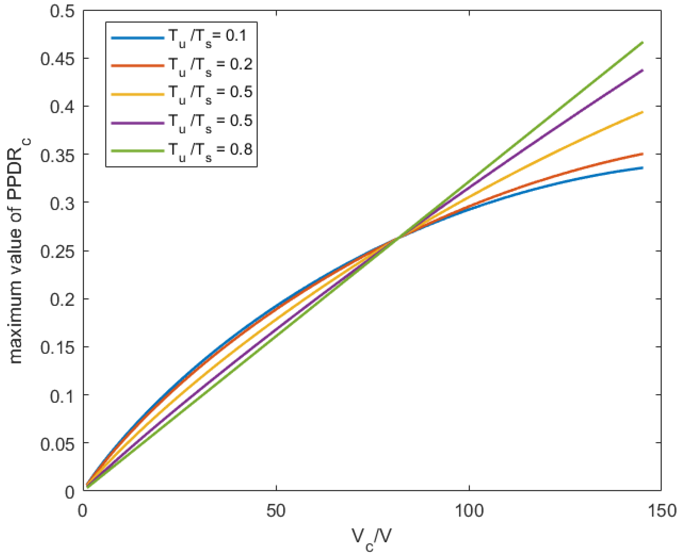
3. Modulation Method for Power Flow Control

The Port Power Distribution Ratio (PPDR) is the power of a energy storage unit to the total power of the converter. A positive PPDR means energy is flowing out of the units and vice verse. PPDR is chosen to evalute the energy management capacity of a energy storage unit in the given topology. The PPDR of super capacitor in ACHB can be calculated as
P P D R c = P c P o u t = i = 1 N = f c f m T i 1 T i i o ( t ) f m V 1 ( t ) d t P o u t
where N is the frequency modulation index, f m is the fundamental frequency, f c is the switching frequency, P o u t is the output power of the converter, V c is the actual voltage of super capacitor. Output power of auxiliary cell in a fundamental cycle is the sum of output power in each carrier cycle as is shown in Equation (4). The current of output current I o ( t ) can be seen as a constant value during one carrier cycle since the carrier cycle is very short and the output voltage of auxiliary cell V 1 ( t ) can be expressed by the switching function according to Equation (3). Hence, the output power of auxiliary cell P c can be rewritten as
P c = i = 1 N = f c f m f m V c i o T i T i 1 T i S 3 ( t ) S 1 ( t ) d t
The integration of switching function in Equation (5) can be expressed by the duty cycle, which be calculated as
S 3 ( t ) S 1 ( t ) d t = d 3 T i d 1 T i T i T i 1
Since the term T i 1 T i is very small, it can be viewed as a differential item. The Equation (6) can be expressed by
P P D R c = 0 2 π ω f m V c i o ( t ) × d 3 ( t ) d 1 ( t ) d t P o u t
The duty cycle term in Equation (7) d 1 ( t ) d 3 ( t ) depends on the modulation method. At present, Level-shift PWM (LSPWM) is widely adopted in multilevel modulation. As is shown in Figure 3, six triangular carriers modulate the sinusoidal reference wave to engender seven voltage levels. The reference wave can be written as
v r e f ( t ) = V m sin ( ω t + θ v )
where V m is the amplitude of reference wave. In order to avoid over-modulation operation regardless of the super capacitor voltage, the V m is assumed to be equal to V d c . Therefore, there are six carrier waves and seven output voltage levels in Figure 3.
The duty cycle term d 1 ( t ) d 3 ( t ) depends on which carrier is modulated by. Considering symmetry between the positive and negative parts of the modulation, the electrical charge increment of positive half cycle is calculated as
When the reference wave amplitude v r e f ( t ) is in area 1 ( v r e f ( t ) [ 0 , V c ] ), the duty cycle term d 1 ( t ) d 3 ( t ) is expressed in the following equation:
d 3 ( t ) d 1 ( t ) = V m sin ω t + θ v V c
Substituting Equation (9) into Equation (7), the electrical charge increment of this symmetric part can be calculated as
P c 1 = V c I om cos ( θ ) π 1 V c 2 V m 2 V m V c asin V c V m
where θ represents the load impedance angle, which equals to θ v θ i . Similarly to the analysis above, the theoretical expression of the charge increment from area 2 to area 3 can be acquired as follows, respectively.
P c 2 = 2 V c I o m π 2 V c V d c V c cos ( θ ) V m 2 V c 2 V m 2 V c cos ( θ ) V m 2 V c 2 V d c 2 + 2 V c V d c V m 2 + V m cos ( θ ) asin V c V m + V m cos ( θ ) asin V c V d c V m 2 V c V d c cos ( θ ) V m 2 V c 2 V m 2
P c 3 = I o m π V c cos ( θ ) V m 2 V c 2 V d c 2 + 2 V c V d c V m 2 V d c cos ( θ ) V m 2 V d c 2 V m 2 V m asin V d c V m cos ( θ ) + V d c cos ( θ ) V m 2 V c 2 V d c 2 + 2 V c V d c V m 2 V m asin V c V d c V m cos ( θ )
Based on the above equations, the power of auxiliary cell can be expressed as
P c = 2 i = 1 P c i
The P P D R c can be calculated according to Equations (7) and (13). The influence of V c and θ on P P D R c with V m = V d c = 220 2 V is shown in Figure 4.
As is shown in Figure 4, by increasing the super capacitor voltage and load power factor, the value of P P D R c keeps increasing. It is inevitable that the P P D R c is determined by the specific operation point in LSPWM. In this paper, hybrid modulation method is proposed to control power flow between ports flexibily.
The proposed hybrid modulation strategy is innovatively utilized in this article to control power flow between cells in ACHB. As is depicted in Equation (7), the output power of each cell is associated with nonorthogonal fundamental component of H-bridge’s output voltage. The power flow can be controlled if the nonorthogonal fundamental component is controllable. Sine pulse width modulation (SPWM) can be added in the modulation strategy to transfer the fundamental component between the ports in ACHB.
In the proposed hybrid modulation strategy, carrier cycle T s is divided into LSPWM operation time T n and SPWM operation time T u as is shown in Figure 5. In LSPWM, operation time T n , all H-bridge cells are modulated by conventional LSPWM uniformly to generate multilevel output voltage. In SPWM operation time T u , two H-bridge cells are modulated by different SPWM, respectively.
d u 1 and d u 2 are the duty cycle of the auxiliary cell and main cell. The duty cycle of auxiliary cell d u 1 ( t ) can be calculated as
d u 1 ( t ) = m u 1 sin ( ω t + θ v u 1 )
where m u 1 and θ v u 1 is the amplitude modulation index and phase of SPWM.
In the proposed hybrid modulation strategy, LSPWM operation part is mainly responsible for the fundamental component of output voltage. The injected SPWM enables degrees of freedom to transfer energy between ports in ACHB without low-order harmonic content.
In hybrid modulation strategy, the reference wave of LSPWM and each SPWM are an ideal sinusoidal wave which can be expressed as
v m l ( t ) = V m l sin ( ω t + θ v )
v m s d c ( t ) = V m s d c sin ( ω t + θ s d c )
v m s c ( t ) = V m s c sin ( ω t + θ s c )
where v m l ( t ) , v m s d c ( t ) , v m s c ( t ) are the reference waves of LSPWM, the SPWM for main cell and the SPWM for auxiliary cell. In order to ensure the magnitude of fundamental output voltage V m , the relationship between the three reference waves can be expressed as:
V m = V m 1 T n T s + ( V m s d c cos ( θ s d c θ v ) + V m s c cos ( θ s c θ v ) ) T u T s V m s d s sin ( θ s d s θ v ) + V m s c sin ( θ s c θ v ) = 0
To simplify the analysis, the power factor angle of each modulation is assumed as 1, which can be expressed as
θ v = θ I = θ s d c = θ s c
In hybrid modulation, the P P D R c can be calculated as
P P D R c = P P D R c L S P W M + P P D R c S P W M
where P P D R c L S P W M , P P D R c S P W M are the port power distribution ratios of auxiliary cell contributed by LSPWM abd SPWM part, respectively.The P P D R c S P W M can be calculated as
P P D R c S P W M = P c S P W M P o u t = V m s c T u V m T s
According to Equations (20) and (21), P P D R c can be controlled by adjusting V m s c and T u .
Define V m s c / V c as SPWM modulation index m s c for the auxiliary cell, which ranges from 0 to 1. According to the aforementioned calculation, the relationship between P P D R c and V c , m s c is shown in Figure 6 when T u / T s is fixed as 0.1 and the RMS of output voltage is 220 V.
When m s c = 1 , P P D R c has the maximum value. P P D R c can be adjusted below the maximum value when m s c ranges from 0 to 1. It is obvious that minimum value of P P D R c is the opposite of maximum value when current direction is contrary to the voltage. The influence of V c and T u / T s on the maximum value of P P D R c is demonstrated in Figure 7. The flexibile power distribution between ports can be realized below the dash line as is shown in Figure 7.

4. SSA-LSTM-Model-Based Power Flow Control Algorithm

This part introduces a power HESS control algorithm based on SSA-LSTM.

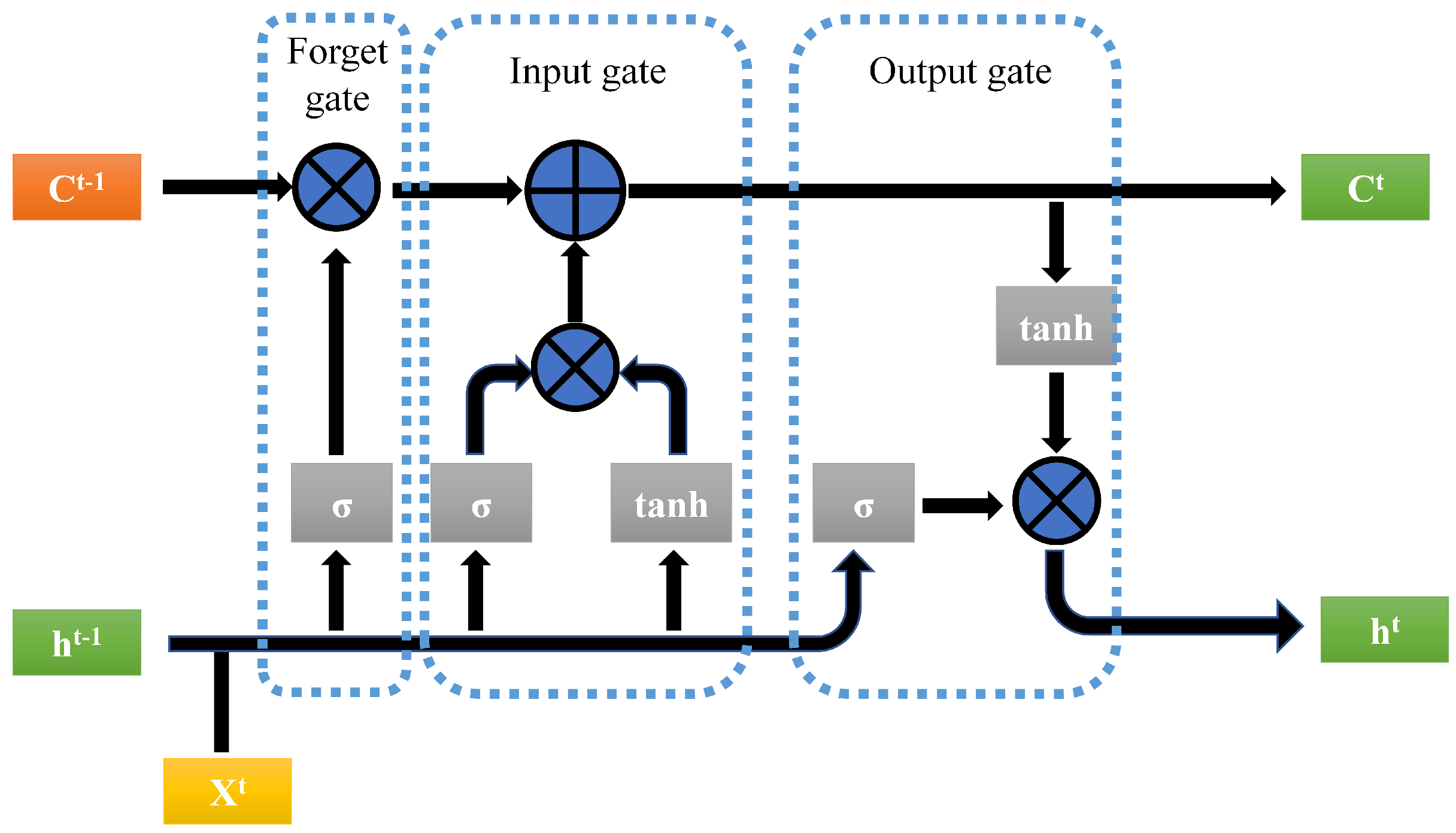
4.1. Long Short-Term Memory (LSTM) Architecture

Long Short-Term Memory (LSTM) have emerged as an effective and scalable model for sequential data recently. Unlike earlier methods such as Recurrent Nerual Network, LSTM model is both adaptive and effective at capturing long-term temporal features [25]. They do not suffer from the optimization obstacles that plague simple recurrent networks (SRNs) and have been widely used to deal with many difficult sequence problems. This includes handwriting recognition, natural language processing, power load data prediction and so on [26].
The core feature of LSTM lies in cell state and gate structure. A schematic of LSTM basic cell can be seen in Figure 8. The hidden layer cell of LSTM has 3 inputs value at time t: input x i of the current input layer, the output h i 1 of the previous hidden layer, and the state value c t 1 of the previous cell. Each cell generates two outputs, which are the current output h i and current cell state value c i . The cell also features three gates (input, forget, and output). These gates can be defined by the following set of equations:
Forget gate:
f t = σ W f h t 1 , x t + b f
Input gate:
i t = σ W i h t 1 , x t + b i
Output gate:
o t = σ W o h t 1 , x t + b o
where W and b present the weight and bias of each gate, σ is the sigmoid function.
Memory cell:
c t = f t c t 1 + i t tanh W c [ h t 1 , x t ] + b c
Cell output:
h t = o t tanh c t
where tanh is the activation function of the LSTM cell and the ⊗ presents matrix multiplication.
LSTM can re

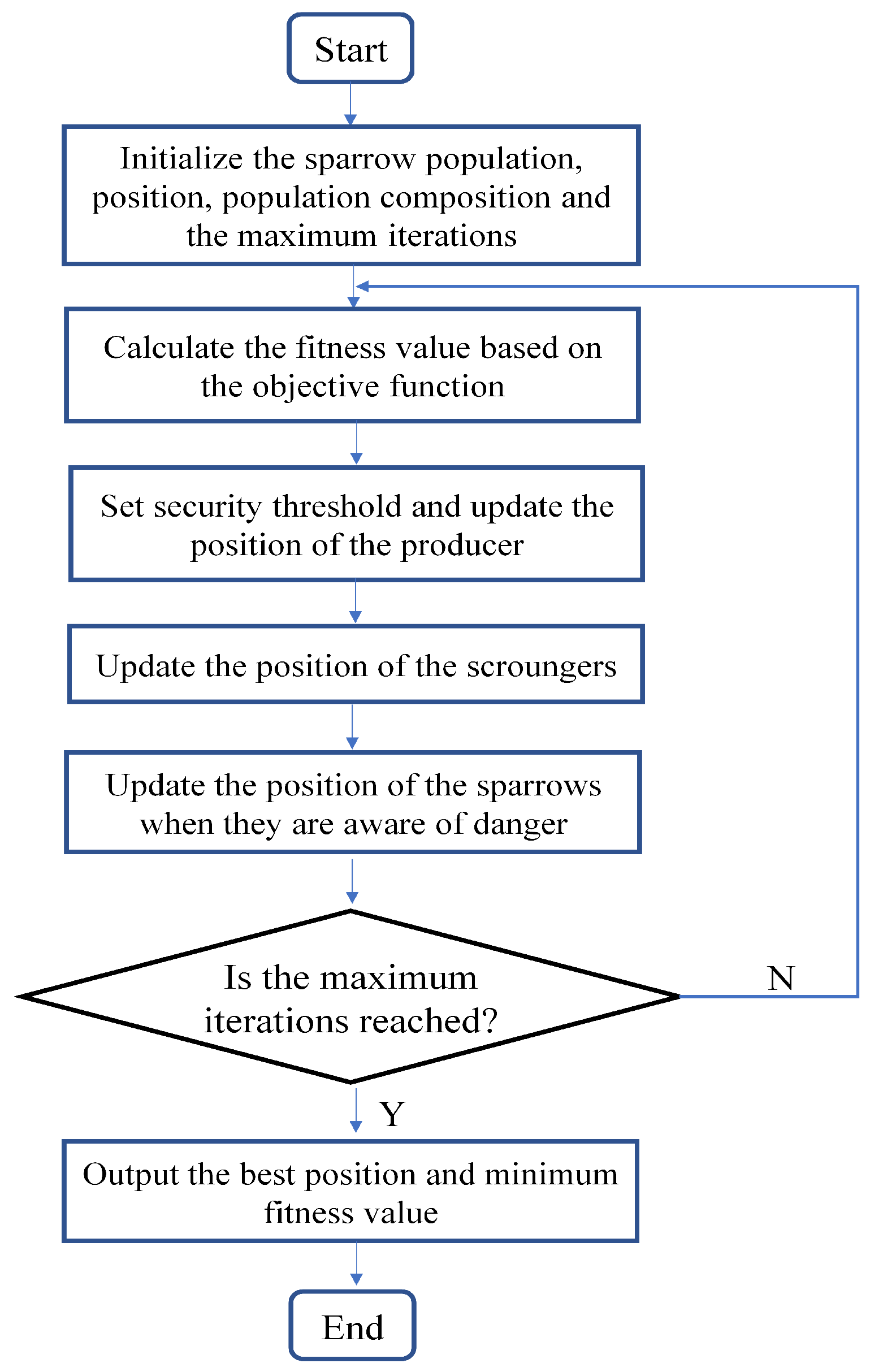
4.2. Application of Sparrow Search Algorithm for LSTM Optimization

Sparrow Search Algorithm is inspired by the behavior of sparrow and uses sparrow position to present optimization variables [27]. It has been proved that SSA is superior in accuracy, convergence speed, stability and robustness compared with other swarm intelligence algorithms [28]. Therefore, SSA is an effective means of parameter optimization.
In the SSA, the sparrow population is divided into two types: producer and scrounger. The producer accounts for searching for food while the scrounger follows the producer in order to get food. According to observations, sparrows can flexibly shift between producer and scrounger. The positions of the sparrow population represent the potential solutions of a optimization problem. The sparrows update their position according to their social role and safety threshold.
Through the above description of sparrow population’s behavior, the flow chart of SSA is shown in Figure 9.
The producers search the foraging area on a large scale and update the location according to (27)
X i , j t + 1 = X i , j t · exp i α × T if R 2 < S T X i , j t + Q · L if R 2 > S T
where t represents iteration. X i , j t is the coordinate of the jth dimension of sparrow i. R 2 [ 0 , 1 ] indicates a warning value and ST is the safety threshold. ST usually takes a value of 0.8. Q is a normally distributed random number. L is a matrix where all the elements are 1, and the size is 1 × d . T is total number of iteration.
When R 2 < ST , it shows that the sparrow population is safe and will search on a large scale. Conversely, the sparrows quickly move to other areas.
For scroungers, they update the position according to (28)
X i , j t + 1 = Q · exp X w o r s t t X i , j t i 2 if i > n / 2 X P t + 1 + X i , j t X P t + 1 · A + · L otherwise
Among them, X p is the best position among producers, X w o r s t is the worst position of the population in this iteration, A is a 1 × d matrix and the elements are randomly assigned as 1 or −1, It indicates search direction.
When i > n / 2 , it means that these sparrows are very hungry, and they will fly to other places by themselves.The remaining scroungers move around the producers because of the rich food and compete with the them to become the producers.
The algorithm assumes that 10% to 20% of the sparrows can be aware of the danger. The sparrows were randomly selected and their position is updated according the Equation (29):
X i , j t + 1 = X b e s t t + κ · X i , j t X b e s t t if f i > f g X i , j t + K · X i , j t X w o r s t t f i f w + ε if f i = f g
Among them, X b e s t is the best position of the population in this iteration; κ is the parameter which controls step; K is a random number of 1 or −1; The fitnes value of sparrow is f i ; f g and f w are the best and worst fitness values of the population. ε is a constant.
In (29), when f i > f g , sparrows are at eht edge of the population, so they fly to the best positon X b e s t of the population. f i = F g indicates that these sparrows are already in the best positoin X b e s t . Due to their alertness, they need to move closer and stay away from the worst position X w o r s t in the meanwhile.
To enhance the prediction accuracy and stability, this paper proposes a hybrid model SSA-LSTM that employs the SSA to optimize the initial weights and bias of LSTM. The major steps of the SSA-LSTM model are elaborated below:
  • Initialize the parameters of the SSA including sparrow population, position, composition and the maximum number of iteration. Initialize the structure of LSTM and the weights and bias of LSTM model are taken as optimization targets.
  • The objective function of SSA is the mean absolute error (MAE) of predicted value of untrained LSTM model compared with raw data.
  • Update the positions of the sparrows based on the results of the objective functions to achieve the optimal initial value of LSTM when reach the maximum iteration number.
  • The particle values of SSA is used as the LSTM model’s weights and bias. Then the training dataset is input into optimized LSTM model to get the final forecasting model.

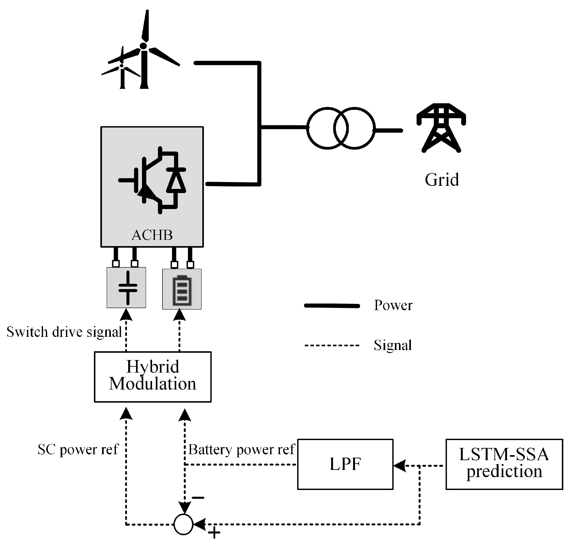
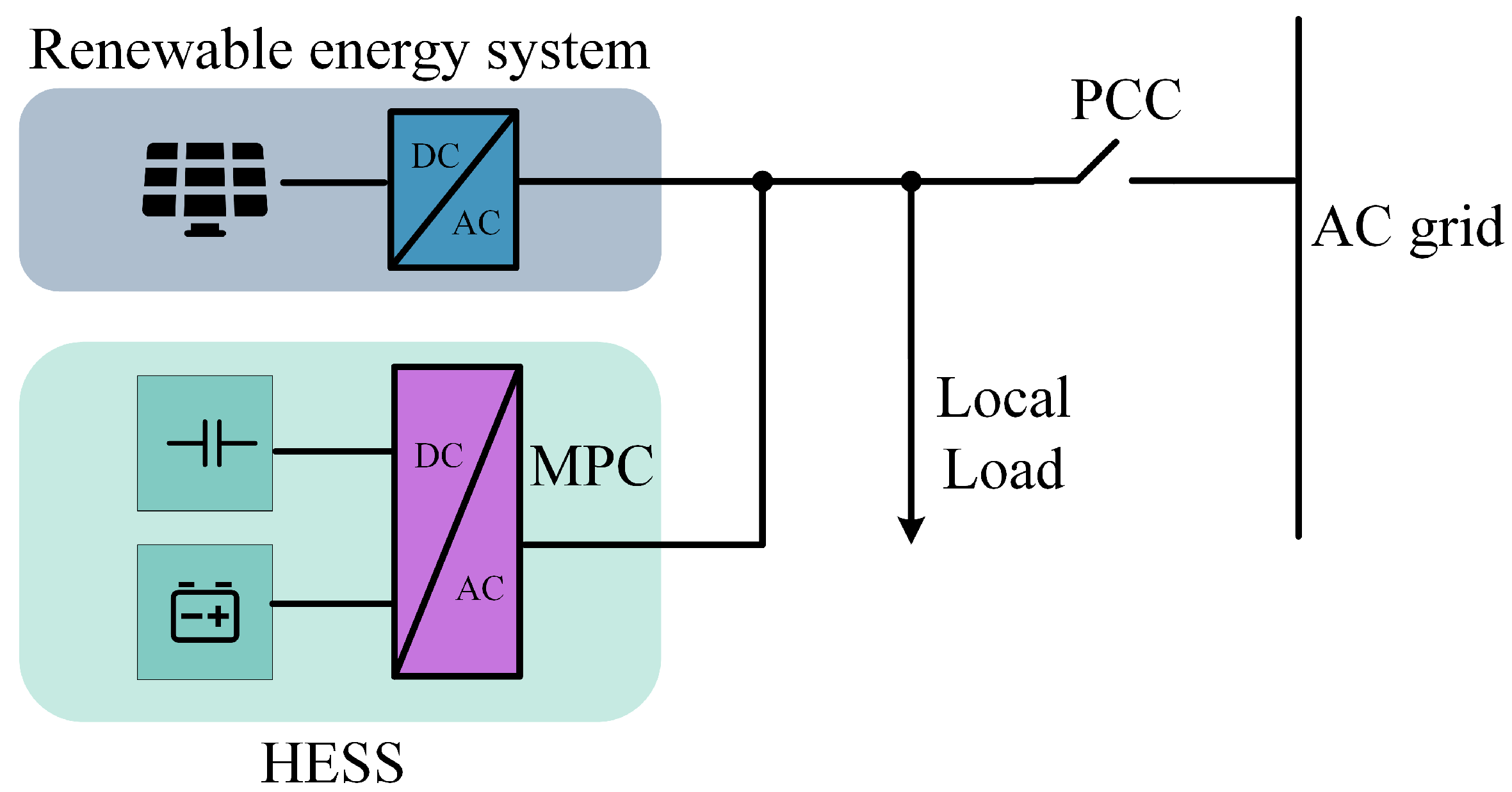
5. Power Distribution Framework

The analysed system architecture is shown in Figure 10. The renewable energy generator and HESS are directly connected to the grid. The HESS, which is composed of ACHB and energy storage units, is responsible for smoothing the power fluctuation.
The proposed control strategy for the framework is divided into the following three steps.
Step 1: Future information is essiential to power distribution. Therefore, the SSA-LSTM model is utilized to obtain the power reference for HESS based on the given multidimensional information.
Step 2: Low pass filter (LPF) is adopted to seperate the frequency component of power reference according to the energy units’ response time. Low frequency is regarded as the power reference for the HESS-E while the rest part is taken as the reference for the HESS-P.
Step 3: The proposed hybrid modulation method is employed to generate the driving signal for the switches in the inverter according to the power reference.

6. Experiment and Analysis

6.1. Data Description

In order to evaluate the proposed model, the experiment was carried out using the actual load data. This is a dataset reports on daily hourly power load and relevant variables from September 2013 to August 2015 in a district of Nanjing, China.
In a power system, the weather information is usually the dominant variable in driving the electricity demand. This dataset includes the date-time, power load, temperature, pressure, wind direction, wind speed and the cumulative number of snow and rain collected from Supervisory Control And Data Acquisition (SCADA) system. The input data of the model is the environmental factors sampled every 15 minutes and the local load while the output data is the power reference for the HESS to keep power balance.
The Root Mean Square Error (RMSE), the Mean Absolute Error (MAE), and the Mean Absolute Percentage Error (MAPE) are used as metrics to evaluate the performance of the model. The three error measures are displayed as follows:
R M S E = 1 T t = 1 T R t F t 2
M A E = 1 T t = 1 T R t F t
M A P E = 1 T t = 1 T R t F t R t
where R t is the real data, F t is the predicted value, and T means the total number of testing data. The entire training data is divided into two groups: training and validation sets. The training sets are used to train different models while the load prediction using validation data set is employed to test the model’s effectiveness. Two simulation validation are carried out based on the different time scales. For a long term power distribution which is longer than one hour, the simulation model is established to validate the performance of software control strategy. For a short term MPC operation, the variable of P P D R can be neglected and model based on Simulink is built to present its output power quality. The parameters of the simulation model are presented in Table 1. Comparisons among different models are given below.

6.2. Experiment Results and Analysis

The prediction errors for each reference model are given in Table 2, and the comparison of prediction results of each reference model for datasets are given in Figure 11.
As can be seen from Table 2 and Figure 11 and Figure 12, the following conclusion can be achieved.
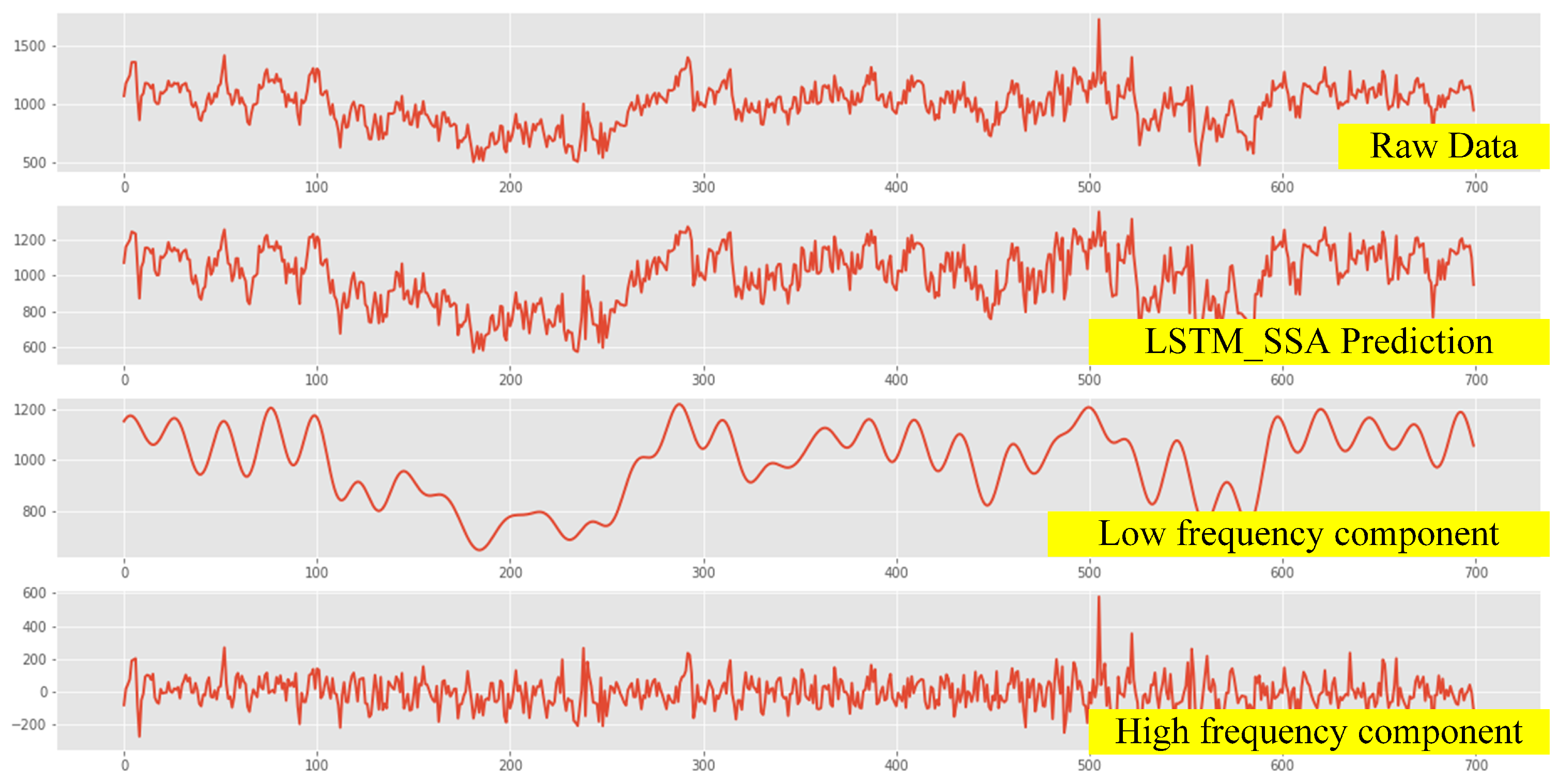
  • The proposed SSA − LSTM model have lower forecasting error, indicating an improved accuracy of the power load prediciton.
  • Compared with the conventional LSTM model, the SSA − LSTM model reduces the prediction error by about 40 % , suggesting its potential for practical application.
  • the SSA + LSTM prediction method proposed in this paper follows the curve of real values closely, which shows outstanding performance of out of sample.
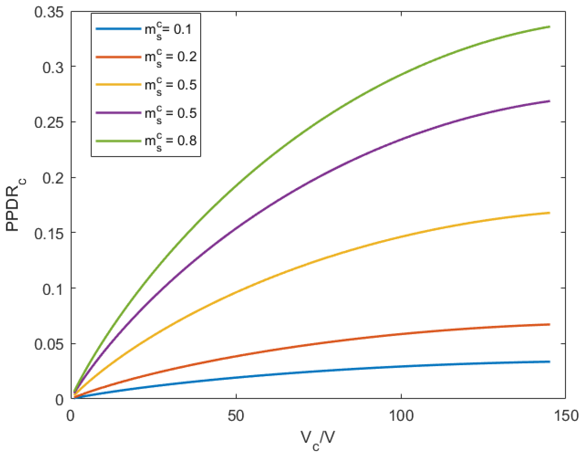
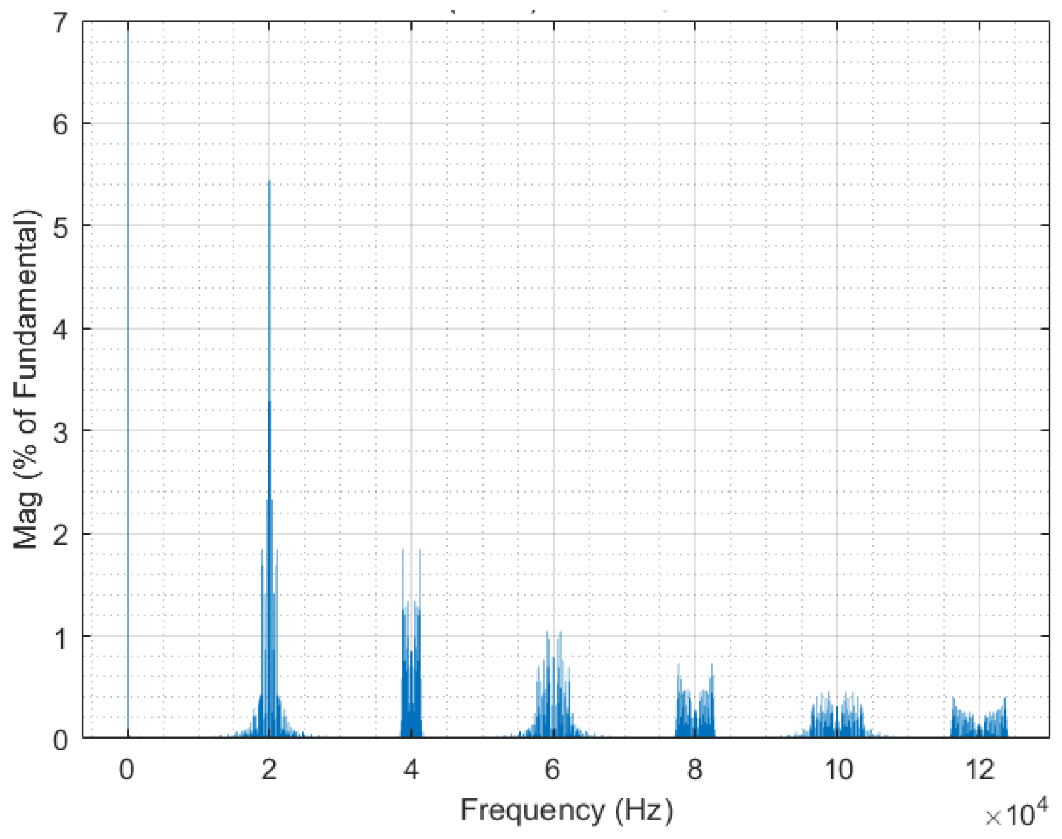
  • In the short term simulation, the proposed modulation strategy can allocate the power flexibily without giving birth to low frequency harmonic content as is shown in Figure 12. The harmonic content is located around the switching frequency.
As is shown in Figure 13. A five order filter is adopted according to the response time of battery. The low frequency component is the power reference for ESS-E while the high frequency component is for the ESS-P. Due to the LPF algorithm and supercapacitor, the charge and discharge cycle of the battery can be reduced. And the result indicates the proposed energy management can significantly reduce the operation cost.

7. Conclusions

In this paper, an framework for power distribution in HESS has been introduced innovatively. This framework is synthetically considered among the main ciruit topology, the modulation method and the power distribution strategy. The software algorithm has the strong flexibility and can be applied into many other topologies and system structures. The SSA-LSTM algorithm is used to obtain the total power output of the HESS, which will be divided into two parts based on frequency by LPF. The proposed hybrid modulation method is applied to drive the switches in the ACHB. Under the proposed power distribution strategy, the MPC operate in a high efficiency because only one stage of power conversion between energy storage and the grid The influence of energy storage capability has been sidestepped based on the assumption that the capability is large enough. Improving long-short-term memory (LSTM) with Sparrow Search Algorithm (SSA), the proposed prediciton method obtain outstanding performance in accuracy. The MAPE of the proposed SSA-LSTM mdoel is 0.0955 and the prediciton error is reduced by 40 % compared with conventional LSTM model. Additionally, the proposed hybrid modulation strategy can allocate the power flexibily between different ports without give birth to low frequency harmonic content. The framework presents an overall solution for HESS covering hardware configuration and control strategy, which is a significant theoretical guide for the construction of HESS. In the future work, the equivalent frequency of the inverter switches need to be reduced to decrease the switching loss. Furthermore, different circuit configurations can be further investigated under the proposed power distribution strategy and more factors will be taken into consideration to improving the stability of the proposed strategy.

Author Contributions

Data curation, J.Z. (Jihong Zhu); Investigation, W.H.; Methodology, W.H.; Project administration, W.H.; Software, W.H. and J.Z. (Jihong Zhu); Writing—original draft, W.H.; Writing—review & editing, J.Z. (Jihong Zhu) and J.Z. (Jing Zhou). All authors have read and agreed to the published version of the manuscript.

Funding

This research was funded by Fundamental Research Funds for the Central Universities (2021XZZX014).

Conflicts of Interest

The authors declare no conflict of interest.

References

  1. Guerrero, J.M.; Blaabjerg, F.; Zhelev, T.; Hemmes, K.; Monmasson, E.; Jemei, S.; Comech, M.P.; Granadino, R.; Frau, J.I. Distributed Generation: Toward a New Energy Paradigm. IEEE Ind. Electron. Mag. 2010, 4, 52–64. [Google Scholar] [CrossRef]
  2. Abu-Elzait, S.; Parkin, R. Economic and Environmental Advantages of Renewable-based Microgrids over Conventional Microgrids. In Proceedings of the 2019 IEEE Green Technologies Conference (GreenTech), Lafayette, LA, USA, 3–6 April 2019; pp. 1–4. [Google Scholar]
  3. Sangwongwanch, A.; Yang, Y.; Blaabjerg, F. High-Performance Constant Power Generation in Grid-Connected PV Systems. IEEE Trans. Power Electron. 2016, 31, 1822–1825. [Google Scholar] [CrossRef] [Green Version]
  4. Yang, B.; Makarov, Y.; Desteese, J.; Viswanathan, V.; Nyeng, P.; McManus, B.; Pease, J. On the use of energy storage technologies for regulation services in electric power systems with significant penetration of wind energy. In Proceedings of the 2008 5th International Conference on the European Electricity Market, Lisboa, Portugal, 28–30 May 2008; pp. 1–6. [Google Scholar] [CrossRef]
  5. Vazquez, S.; Lukic, S.; Galvan, E.; Franquelo, L.G.; Carrasco, J.M.; Leon, J.I. Recent advances on Energy Storage Systems. In Proceedings of the IECON 2011—37th Annual Conference of the IEEE Industrial Electronics Society, Melbourne, VIC, Australia, 7–10 November 2011; pp. 4636–4640. [Google Scholar] [CrossRef]
  6. Wei, Z.; Quan, Z.; Wu, J.; Li, Y.; Pou, J.; Zhong, H. Deep Deterministic Policy Gradient-DRL Enabled Multiphysics-Constrained Fast Charging of Lithium-Ion Battery. IEEE Trans. Ind. Electron. 2021, 1. [Google Scholar] [CrossRef]
  7. Wu, J.; Wei, Z.; Liu, K.; Quan, Z.; Li, Y. Battery-Involved Energy Management for Hybrid Electric Bus Based on Expert-Assistance Deep Deterministic Policy Gradient Algorithm. IEEE Trans. Veh. Technol. 2020, 69, 12786–12796. [Google Scholar] [CrossRef]
  8. Dorn-Gomba, L.; Magne, P.; Danen, B.; Emadi, A. On the Concept of the Multi-Source Inverter for Hybrid Electric Vehicle Powertrains. IEEE Trans. Power Electron. 2018, 33, 7376–7386. [Google Scholar] [CrossRef]
  9. Wu, J.; Wei, Z.; Li, W.; Wang, Y.; Li, Y.; Sauer, D.U. Battery Thermal- and Health-Constrained Energy Management for Hybrid Electric Bus Based on Soft Actor-Critic DRL Algorithm. IEEE Trans. Ind. Inform. 2021, 17, 3751–3761. [Google Scholar] [CrossRef]
  10. Luo, X.; Wang, J.; Dooner, M.; Clarke, J. Overview of current development in electrical energy storage technologies and the application potential in power system operation. Appl. Energy 2015, 137, 511–536. [Google Scholar] [CrossRef] [Green Version]
  11. Zhang, Y.; Jiang, Z.; Yu, X. Control Strategies for Battery/Supercapacitor Hybrid Energy Storage Systems. In Proceedings of the 2008 IEEE Energy 2030 Conference, Atlanta, GA, USA, 17–18 November 2008; pp. 1–6. [Google Scholar] [CrossRef]
  12. Jung, H.; Conficoni, C.; Tilli, A.; Hu, T. Modeling and control design for power systems driven by battery/supercapacitor hybrid energy storage devices. In Proceedings of the 2013 American Control Conference, Washington, DC, USA, 17–19 June 2013; pp. 4283–4288. [Google Scholar] [CrossRef]
  13. Sun, L.; Feng, K.; Chapman, C.; Zhang, N. An Adaptive Power-Split Strategy for Battery-Supercapacitor Powertrain—Design, Simulation, and Experiment. IEEE Trans. Power Electron. 2017, 32, 9364–9375. [Google Scholar] [CrossRef]
  14. Zhou, Y.; Huang, Z.; Liao, H.; Li, H.; Jiao, Y.; Peng, J. A Predictive Set-Point Modulation Energy Management Strategy for Hybrid Energy Storage Systems. IEEE Trans. Ind. Appl. 2019, 55, 6266–6277. [Google Scholar] [CrossRef]
  15. Rahimi, T.; Ding, L.; Kheshti, M.; Faraji, R.; Guerrero, J.M.; Tinajero, G.D.A. Inertia Response Coordination Strategy of Wind Generators and Hybrid Energy Storage and Operation Cost-Based Multi-Objective Optimizing of Frequency Control Parameters. IEEE Access 2021, 9, 74684–74702. [Google Scholar] [CrossRef]
  16. Wu, H.; Liu, T.; Yang, T.; Wang, J.; Ding, S.; Xing, Y. A modified SVPWM strategy applied to a three-phase three-port bidirectional AC-DC rectifier for efficiency enhancement. In Proceedings of the 2017 IEEE Energy Conversion Congress and Exposition (ECCE), Cincinnati, OH, USA, 1–5 October 2017. [Google Scholar]
  17. Bhattacharjee, A.K.; Kutkut, N.; Batarseh, I. Review of Multiport Converters for Solar and Energy Storage Integration. IEEE Trans. Power Electron. 2019, 34, 1431–1445. [Google Scholar] [CrossRef]
  18. Wang, J.; Sun, K.; Xue, C.; Liu, T.; Li, Y. Multi-Port DC-AC Converter with Differential Power Processing DC-DC Converter and Flexible Power Control for Battery ESS Integrated PV Systems. IEEE Trans. Ind. Electron. 2021, 1. [Google Scholar] [CrossRef]
  19. Mei, Q.; Xu, Z.; Wu, W. A novel multi-port DC-DC converter for hybrid renewable energy distributed generation systems connected to power grid. In Proceedings of the 2008 IEEE International Conference on Industrial Technology, Chengdu, China, 21–24 April 2008; pp. 1–5. [Google Scholar] [CrossRef]
  20. Liu, C.; Ruan, J.; Li, G.; Deng, Y.; He, X. A Space Vector Modulation Strategy for Maximum Port Power Distribution Range in a Three-Port Three-Phase Converter. In Proceedings of the 2020 IEEE 9th International Power Electronics and Motion Control Conference (IPEMC2020-ECCE Asia), Nanjing, China, 29 November–2 December 2020; pp. 2380–2384. [Google Scholar]
  21. Liu, L.; Li, H.; Wu, Z.; Zhou, Y. A Cascaded Photovoltaic System Integrating Segmented Energy Storages With Self-Regulating Power Allocation Control and Wide Range Reactive Power Compensation. IEEE Trans. Power Electron. 2011, 26, 3545–3559. [Google Scholar] [CrossRef]
  22. Xiaoliang, H.; Hiramatsu, T.; Yoichi, H. Energy Management Strategy based on frequency-varying filter for the battery supercapacitor hybrid system of Electric Vehicles. In Proceedings of the 2013 World Electric Vehicle Symposium and Exhibition (EVS27), Barcelona, Spain, 17–20 November 2013; pp. 1–6. [Google Scholar] [CrossRef] [Green Version]
  23. Schwendemann, R.; Sommer, F.; Hiller, M. A resonant supplied cascaded H-Bridge Cell for a Series Hybrid Cascaded H-Bridge Converter used as a Power Hardware in the Loop Emulator. In Proceedings of the 2020 IEEE 21st Workshop on Control and Modeling for Power Electronics (COMPEL), Aalborg, Denmark, 9–12 November 2020; pp. 1–8. [Google Scholar] [CrossRef]
  24. Yu, H.; Liu, J.; Yao, W.; Lu, Z.; Ji, Y. An improved drive signal exchange strategy for cascaded H-bridge topology. In Proceedings of the 2018 IEEE Applied Power Electronics Conference and Exposition (APEC), San Antonio, TX, USA, 4–8 March 2018; pp. 2476–2481. [Google Scholar] [CrossRef]
  25. Hochreiter, S.; Schmidhuber, J. Long Short-Term Memory. Neural Comput. 1997, 9, 1735–1780. [Google Scholar] [CrossRef] [PubMed]
  26. Greff, K.; Srivastava, R.K.; Koutník, J.; Steunebrink, B.R.; Schmidhuber, J. LSTM: A Search Space Odyssey. IEEE Trans. Neural Netw. Learn. Syst. 2017, 28, 2222–2232. [Google Scholar] [CrossRef] [PubMed] [Green Version]
  27. Xue, J.; Shen, B. A novel swarm intelligence optimization approach: Sparrow search algorithm. Syst. Sci. Control. Eng. 2020, 8, 22–34. [Google Scholar] [CrossRef]
  28. Song, W.; Liu, S.; Wang, X.; Wu, W. An Improved Sparrow Search Algorithm. In Proceedings of the 2020 IEEE Intl. Conf. on Parallel Distributed Processing with Applications, Big Data Cloud Computing, Sustainable Computing Communications, Social Computing Networking (ISPA/BDCloud/SocialCom/SustainCom), Exeter, UK, 17–19 December 2020; pp. 537–543. [Google Scholar] [CrossRef]
Figure 1. Circuit configurations for renewable energy system with HESS.
Energies 14 08312 g001
Figure 2. Single-phase two-cell asymmetrical hybrid CHB MLI.
Energies 14 08312 g002
Figure 3. Seven-level LSPWM technique.
Energies 14 08312 g003
Figure 4. Influence of V c and θ on the electrical charge increment.
Energies 14 08312 g004
Figure 5. Proposed modulation strategy.
Energies 14 08312 g005
Figure 6. Influence of V c and m s c on P P D R c .
Energies 14 08312 g006
Figure 7. Influence of V c and T u / T s on the maximum value of P P D R c .
Energies 14 08312 g007
Figure 8. Schematic of LSTM block.
Energies 14 08312 g008
Figure 9. Program flow chart of SSA.
Energies 14 08312 g009
Figure 10. The flow chart of proposed power distribution strategy HESS.
Energies 14 08312 g010
Figure 11. (a) Intercepted Fragment of Prediction results. (b) Prediction accuracy comparison between different models.
Energies 14 08312 g011
Figure 12. Spectrum of output voltage under the fixed P P D R .
Energies 14 08312 g012
Figure 13. Intercepted Fragments of Simulation results.
Energies 14 08312 g013
Table 1. Parameters of Simulated ACHB system.
ParametersValue
DC source voltage V d c 900 V
Capacitor voltage V c 300 V
Output frequency f50 Hz
Carrier frequency f c 20 kHz
Power factor c o s θ 1
Table 2. Comparison between Different Models.
RMSE (kW)MAE (kW)MAPE
ANN2646.9132291.3460.304
LSTM1342.607975.7460.167
SSA-LSTM1109.224664.8870.0955
Publisher’s Note: MDPI stays neutral with regard to jurisdictional claims in published maps and institutional affiliations.

