Abstract
The true bipolar modular multilevel converter-based multi-terminal direct current (MMC-MTDC) DC transmission line is prone to single-pole grounding fault, which may cause overload and overcurrent of the non-fault DC line with fault poles, resulting in system protection misoperation and system collapse. Therefore, the power transfer control strategy should be adopted to improve system stability. In addition, considering that the commutator stations of true bipolar MMC-MTDC system may have unipolar faults, it is necessary to adopt the control strategy of inter-pole power transfer or inter-station power transfer to improve the transmission capacity of the system under fault conditions. In this paper, a power transfer control strategy is proposed, which is widely applicable to MMC-MTDC system. In the case of line fault, the power transfer takes into account the line power margin and the power margin of converter station. The inter-pole power transfer is better than the inter-station power transfer under the converter station fault condition, and the inter-station power transfer takes into account the priority of the power margin of the converter station. At the same time, based on the Zhangbei four-terminal flexible direct current transmission project, the Zhangbei four-terminal flexible direct current transmission system is built by using PSCAD/EMTDC, and the flexibility and effectiveness of the proposed strategy are verified by simulation.
1. Introduction
The flexible DC power grid based on module multilevel converter (MMC) has the advantages of economy, reliability, and flexibility [1,2,3,4,5], very high voltages can be produced by cascading several submodule units together [6,7], it is easy to expand to high pressure and large capacity field. MMC-MTDC is of great significance to the safe and stable operation of China’s power grid. It can be used in the fields of large-scale renewable energy generation and grid connection, asynchronous AC power grid system interconnection, island operation and power supply, urban distribution network and remote power transmission, etc. It has become a new energy grid connection scheme with the most technical advantages. However, with the increase of the number of terminals, the coordination of control objectives between multiple converter stations will become more complex.
At present, the coordinated control strategies applicable to MMC-MTDC system are all based on pseudo-bipolar connection MMC-MTDC system, and there are mainly three kinds: single-point DC voltage method, DC voltage margin control, and DC voltage droop control [8,9,10]. The control strategy of single-point DC voltage method relies too much on inter-station communication and is not reliable. DC voltage margin control strategy requires high capacity of the main converter station, which can easily lead to overload of the main converter station. The DC voltage droop control strategy is relatively flexible because it regulates the DC voltage and power of the system together, and maintains the voltage stability and power balance of the flexible DC transmission system. The coordination control strategy of true bipolar connection MMC-MTDC system includes power transfer control strategy [11,12,13,14,15,16]. Compared with the pseudo-bipolar connection MMC-MTDC system, the true bipolar connection MMC-MTDC system has more flexible operation mode. The upper and lower poles form two independent current paths through the metal loop, and the power transfer control strategy is based on this unique operation mode, which makes the coordination control of the system more flexible.
Literature [11] proposes a power substitution strategy suitable for true bipolar multiterminal flexible HVDC transmission systems. However, for line faults, in the case of multi-channel, only line power margin is considered, without considering the capacity of converter station. In literature [12], the power transfer control strategy and the power rapid drop control strategy are mentioned, but the theory and control strategy are ignored. Literature [13] mentioned the applicability of symmetrical bipolar MMC operation mode to the power transfer control strategy, and proposed to adjust the power rise rate to optimize the power transfer control strategy, but the analysis was limited to the fault of the two-terminal converter station. Literature [14] points out that the power rapid drop control strategy is applicable to the pseudo bipolar, and the power transfer control strategy is applicable to the true bipolar. The voltage reference value and the power reference value are modified simultaneously, so as to reduce the over-current of the fault pole non-fault line. Literature [15] proposed that the power emergency coordinated control strategy was the optimized power transfer control strategy, and supplemented and improved the power transfer control strategy on the basis of literature [11]. The power transfer control strategy proposed in literature [16] is applicable to the locking fault of converter station, and the applicability of the operation mode of converter station to the power transfer control strategy is summarized, this strategy has been used in the demonstration project of Wudong power station transmission of ultra-high voltage (UHV) multi-terminal DC in Guangdong and Guangxi.
Based on the above power transfer control strategy, a power transfer control strategy suitable for MMC-MTDC system is proposed in this paper. Based on the Zhangbei flexible DC project, a simulation model of Zhangbei four-terminal flexible HVDC transmission system is built by using PSCAD/EMTDC to verify the feasibility and flexibility of the proposed power transfer control.
2. MMC-MTDC System and Its Power Transfer Conditions
2.1. Basic Working Principle of MMC
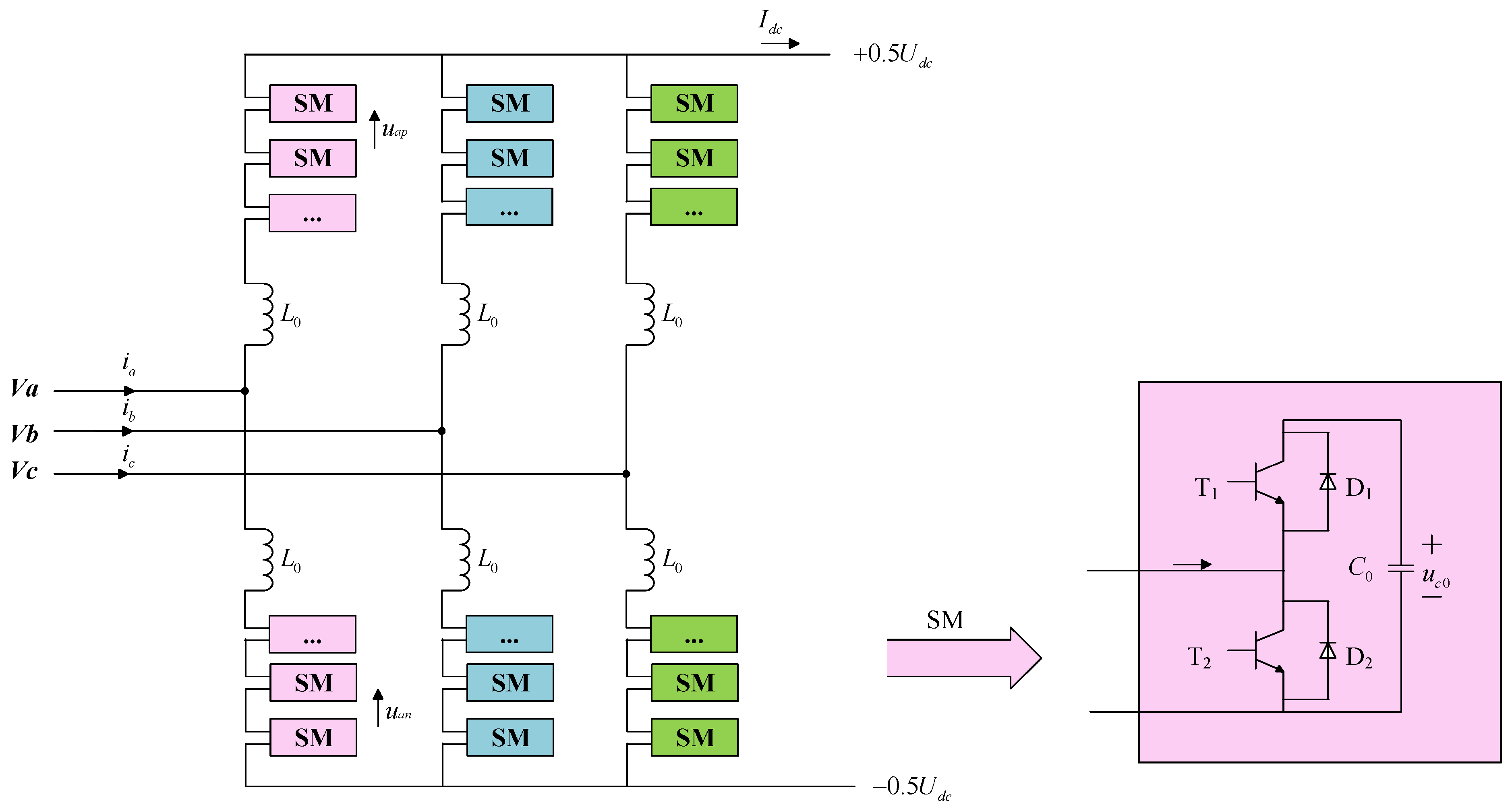
The topological structure of MMC is shown in Figure 1. MMC is a three-phase six-bridge arm multi-level converter. Each bridge arm unit is composed of sub-modules(SM) and bridge arm reactor . Half bridge SM structure consists of IGBT including T1 and T2, inverse shunt diodes including D1 and D2, DC side capacitors [17].
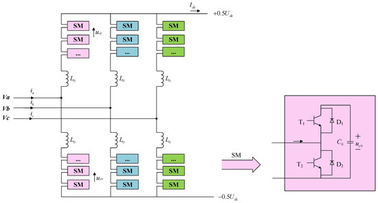
Figure 1.
Schematic diagram of MMC three-phase topology.
Suppose that the potential of a neutral point is 0, and taking Phase A as an example for analysis, the voltage of the AC port of Phase A to the hypothetical neutral point is ,the DC side port voltage is , the potential of the positive and negative bus is +0.5 and −0.5 . The voltage of MMC bridge arm is superimposed by multiple SMs, so let the output voltage and of the upper and lower bridge arms of MMC be and respectively, It can be deduced that and satisfies the following conditions:
Similarly, in order to satisfy the voltage balance, it is easy to obtain and to satisfy the constraint conditions as follows:
Under the constraints of Equations (1) and (2), the DC voltage can be output by adjusting the input or removal of SM in the upper and lower bridge arms of the MMC.
2.2. Typical True Bipolar MMC-MTDC System
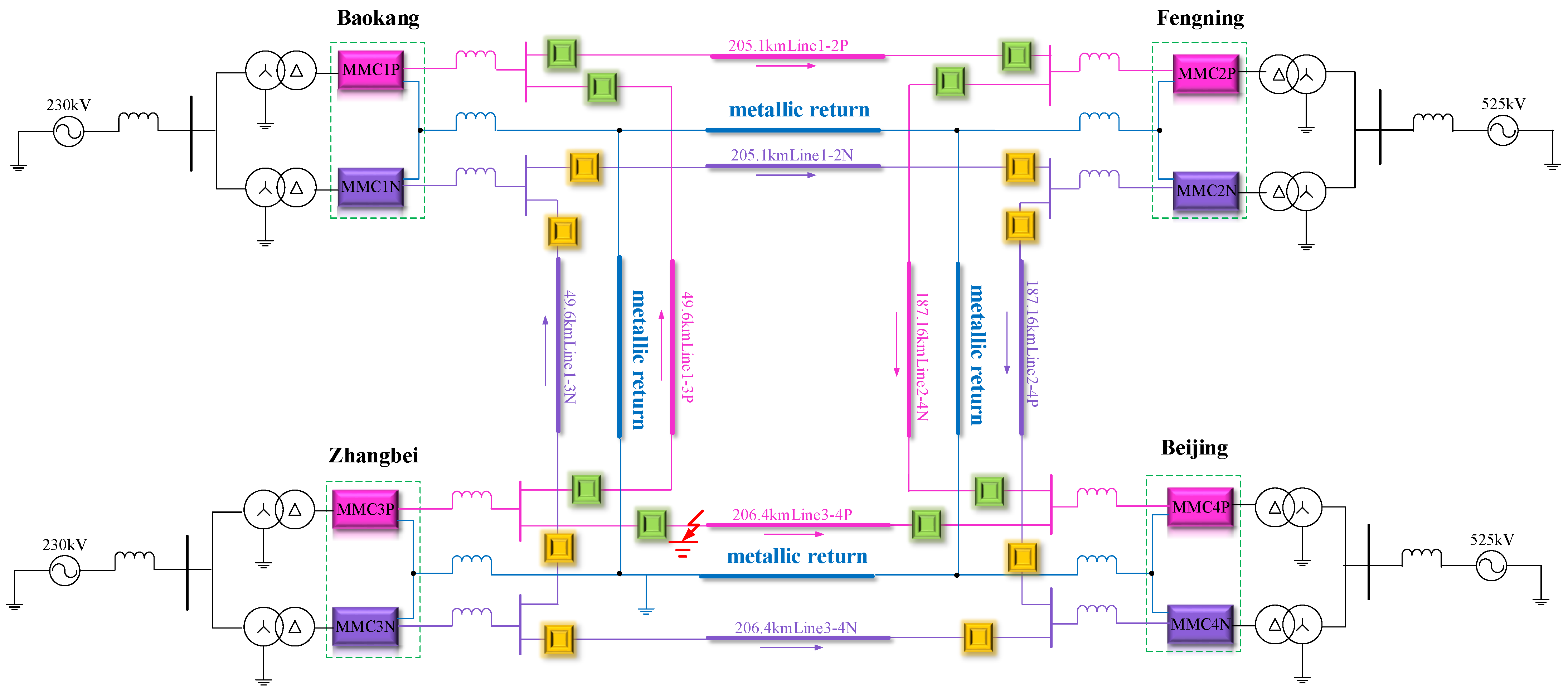
Zhangbei four-terminal flexible HVDC transmission project is a typical true bipolar MMC-MTDC project, with topology as shown in Figure 2 and parameters as shown in Table 1. The four half-bridge converter stations of the Zhangbei flexible DC transmission system are respectively: Kangbao Station MMC1, Fengning Station MMC2, Zhangbei Station MMC3, Beijing Station MMC4. MMC1 and MMC3 are converter stations at the power sending end connected to the wind farm respectively; MMC2 is the regulating converter station connected with the pumped storage station; MMC4 is the converter station at the power receiving end. MMC1 AC network side rated voltage: 230 KV, rated continuous operating voltage is 242 kV; MMC2 AC network side rated voltage: 525 KV; MMC3 AC network side rated voltage: 230 KV; MMC4 AC network side rated voltage 525 KV. The rated capacity of MMC1 and MMC2 is 1500 MW, the rated capacity of MMC3 and MMC4 is 3000 MW. The length of each section of the line is: MMC1-MMC3 line is 49.6 km; MMC1-MMC2 line is 205.1 km; the MMC2-MMC4 line is 186.5 km (Including 29.5 km for the section of the same tower as MMC3-MMC4); MMC3-MMC4 line is 205.8 km (including 29.5 km of the section of the same tower as MMC2-MMC4). A 150 mH flat-wave reactor and a DC circuit breaker with a rated current of 3 kA are installed at both ends of each DC transmission line. The overhead DC transmission line consists of a four-end loop network, and the upper and lower poles form a current path through metal loops, which is equivalent to two independent loops.
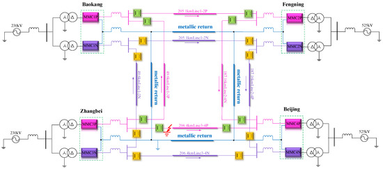
Figure 2.
Topology of four terminal flexible direct current transmission system.

Table 1.
Parameter of four-terminal flexible direct current transmission system.
2.3. True Bipolar MMC-MTDC Operation Mode
The true bipolar MMC-MTDC system has flexible operation mode, and there are three main operation modes:
- Bipolar ground operation with metal loop. Metal loop can provide unbalanced current path, and both positive and negative converter stations can operate independently through the metal loop. The bipolar MMC-MTDC system is equivalent to two independent loop networks and has the condition of power transfer.
- Bipolar with metal-free loop grounding operation. Metal-free loop layer provides current path, and positive and negative converter stations run in series. The bipolar MMC-MTDC system is equivalent to a ring network and does not have the condition of power transfer.
- Unipolar with metal loop ground operation. The fault pole is out of operation, and the non-fault pole provides the current loop through the metal loop, which is equivalent to the monopole MMC-MTDC system and does not have the condition of power transfer.
To sum up, the feasibility conditions of having the power transfer are: the converter stations of the true bipolar MMC-MTDC system are all in operation and the metal loop can provide unbalanced current path.
2.4. True Bipolar MMC-MTDC Control Mode
Generally, there are two control modes of converter station: bipolar control mode and unipolar control mode. By flexibly combining the two control modes of true bipolar MMC-MTDC system, three control modes can be obtained, as follows:
- When both the upper and lower stages of the converter station adopt bipolar control mode, the power reference value of the converter station can be equally distributed between the upper and lower stages of the converter station.
- When the unipolar/bipolar mixed control mode is used, the power reference value of the unipolar control mode of the converter station is independently controlled, and the power reference value of the bipolar control mode of the converter station is the total power reference value of the bipolar. When the unipolar converter station of bipolar control mode fails, the power transfer cannot be carried out.
- When both the upper and lower stages of the converter station adopt unipolar control mode, the power reference values of the upper and lower levels of the converter station are independently controlled, and the power transfer cannot be carried out in this control mode.
To sum up, the non-fault pole adopts the bipolar control mode, and the true bipolar MMC-MTDC system commutator station can carry out the power transfer for the single-pole fault.
3. Power Transfer Control Strategy
3.1. DC Line Fault
In case of unipolar DC line fault, the fault pole and non-fault pole of the converter at the sending end or receiving end should be adjusted synchronously. The following is to transfer the power to the converter station at the sending end.
When a unipolar short circuit fault occurs in one pole DC line of the MMC-MTDC system, it may cause overload of the non-fault line and lead to the wrong operation of the DC circuit breaker, which affects the stability and reliability of the system. It is necessary to reduce the power of the fault pole sending end and increase the power of the non-fault pole sending end, so as to keep the total power of the upper and lower poles unchanged as much as possible. By transferring part of the overload power of the fault pole to the non-fault pole, the line overload problem can be effectively solved.
Consider non-fault line overload:
is the active power transmitted by the fault pole non-fault line, which can be calculated by the voltage at each terminal and the reference value of the original active power of the single-pole converter station combined with the simple network directed graph; is the maximum transmissible power of a unipolar DC line, which is obtained from system parameters.
Consider full load of converter station:
is the rated capacity of the unipolar converter station, which can be obtained by querying system parameters; is the original active power reference value of the monopole converter station, the given value. Combined with the above related factors, the reference values of the active power of the upper and lower levels of the converter station after correction can be obtained in case of unipolar grounding fault, as shown in the formula:
In the formula, is the active power reference value after fault pole correction; reference value of active power after correction of non-fault pole; is the revision of the active power reference value.
If , then there is no line overload and no need to transfer the power, .
This power transfer control strategy is also applicable to complex multi-channel power grid, and there is no need to discuss the multi-channel situation separately.
3.2. Converter Station Fault
In case of converter station faults, the control strategy of inter-pole power transfer should be given priority, and then the control strategy of inter-station power transfer should be considered to ensure the power output of the sending end to the greatest extent, and improve the power transfer ability of the MMC-MTDC system under converter station fault conditions.
When a unipolar fault occurs at the converter station at the sending end, the fault pole of the converter station is unable to transmit active power, then the reference value of active power after correction of the fault pole of the converter station is 0, i.e., . In order to ensure the stability of the MMC-MTDC system and reduce generator tripping and load shedding at the sending end, the non-fault pole of the converter station should transfer the active power transmitted by the fault pole to the maximum extent, so it is necessary to increase —the reference value of the active power after the correction of the non-fault pole of the converter station. If —the original active power reference value of the fault pole of the converter station is not greater than the upper limit of the active power margin of the single pole of the converter station, so —the active power reference value corrected by the non-fault pole of the converter station at this sending end is the original active power reference value of the converter station; If —the original active power reference value of the converter station is greater than the upper limit of the single pole active power margin of the converter station, then —the active power reference value after the correction of the non-fault pole of the converter station at the sending end is the rated capacity of the converter station.
3.2.1. Inter-Polar Power Transfer Control Strategy
Assuming that the upper pole of No.1 converter station at the MMC-MTDC sending end is locked, if , then the non-fault poles of the fault converter station can transfer power, and the reference values of the active power of the upper and lower poles of the fault converter station after correction are as follows:
3.2.2. Inter-Station Power Control Strategy
As above, it is assumed that the upper pole of MMC-MTDC sending end No.1 converter station is locked. If , so the non-fault pole of No.1 converter station at the sending end cannot fully compensate for the lost active power, and the inter-station active power transfer is required. After correcting the active power of the upper and lower poles of the fault converter station, the reference value is as follows:
Considering the priority level of power margin, the reference value of the active power of the upper and lower poles of the non-fault converter station after correction is as follows:
Among the remaining converter stations at the sending end, the one with the largest power margin is selected for active power compensation. If , the maximum power margin converter station can be fully compensated; if , the converter station with the largest power margin cannot fully compensate for the active power lost, the one with the largest power margin shall be selected from the remaining converter stations at the sending end for active power compensation, and so on, other non-fault converter stations shall be corrected:
When the number of terminals x = 2, that is to say, only the No.2 converter station at the terminal can carry out inter-station active power transfer. After correction, the reference value of the upper and lower pole active power of the No.2 converter station is as follows:
4. Simulation Verification of Power Transfer Control Strategy
In order to verify the flexibility and effectiveness of the above power transfer control strategy, based on the topology and system parameters of the Zhangbei four-terminal flexible HVDC transmission system, a simulation model of the Zhangbei four-terminal flexible HVDC transmission system as shown in Figure 2 is built in PSCAD. MMC1 adopts power and repower control, MMC2 adopts DC voltage and repower control. MMC3 adopts power and repower control. MMC4 uses power and repower control.
4.1. DC Line Fault Simulation
When the DC line is in fault, if the fault pole non-fault line appears overload and overcurrent phenomenon, the power transfer is carried out. When the power transfer occurs, the transmission capacity of the DC grid and the capacity of the converter station participating in the power transfer are comprehensively considered. The initial power reference value of MMC1 converter station is set as 1200 MW, the initial power reference value of MMC3 converter station is set as 2400 MW, the initial power reference value of MMC4 converter station is set as −2600 MW, and the MMC2 converter station is set as the balance station to stabilize the DC voltage of the whole network. Under normal conditions, the total power of the converter station is equally distributed between the upper and lower poles, so the initial power reference values of a single converter station MMC1P, MMC3P, and MMC4P are 600 MW, 1200 MW, and −1300 MW respectively. Similarly, the initial power reference values of a single converter station MMC1N, MMC3N, and MMC4N at the lower pole are 600 MW, 1200 MW, and −1000 MW respectively. Table 1 shows the rated power of each converter station, and the power margin of each converter station can be obtained. Set the fault as L34P single-pole grounding fault, and the fault occurs at 1.0 s.
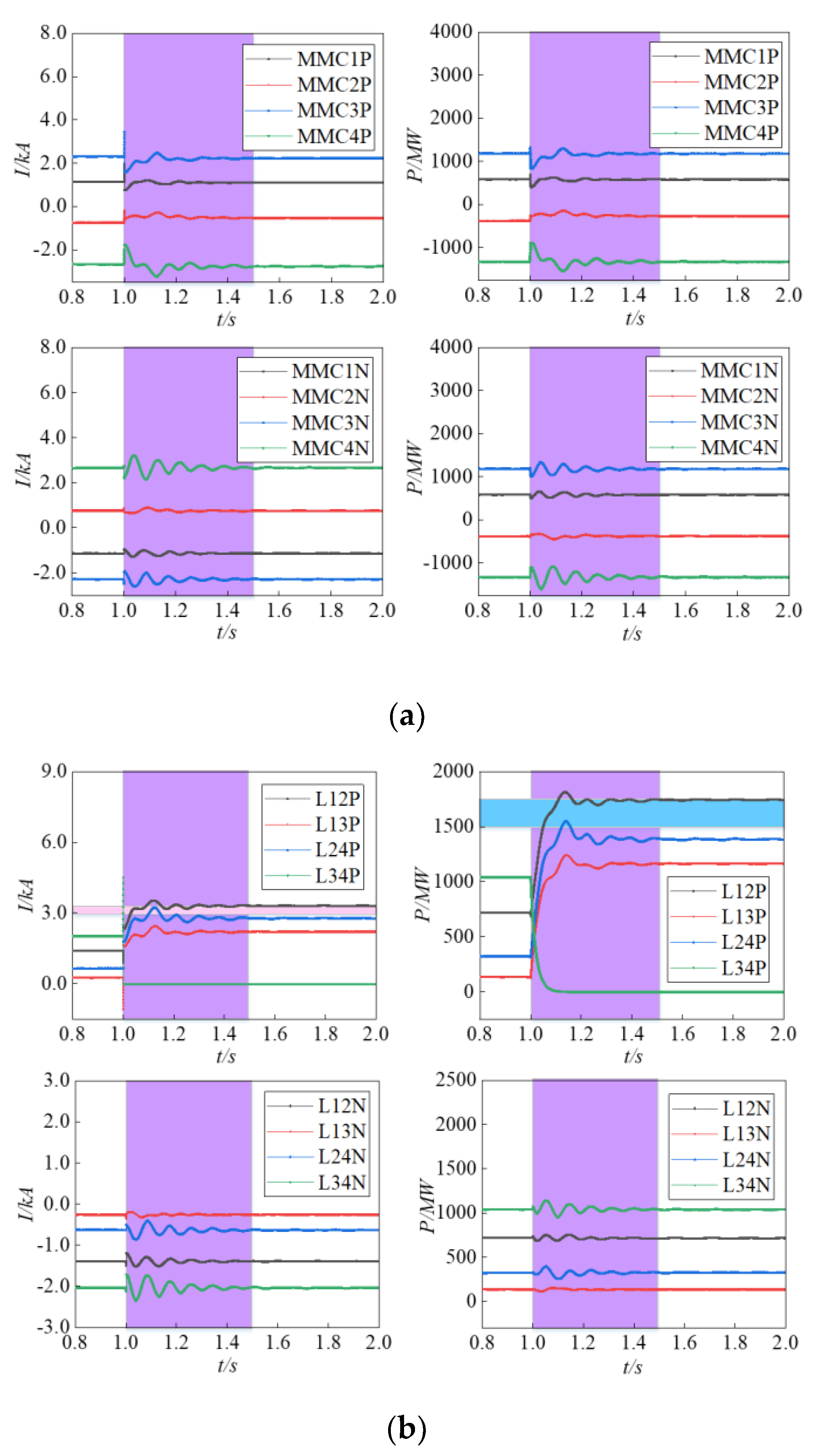
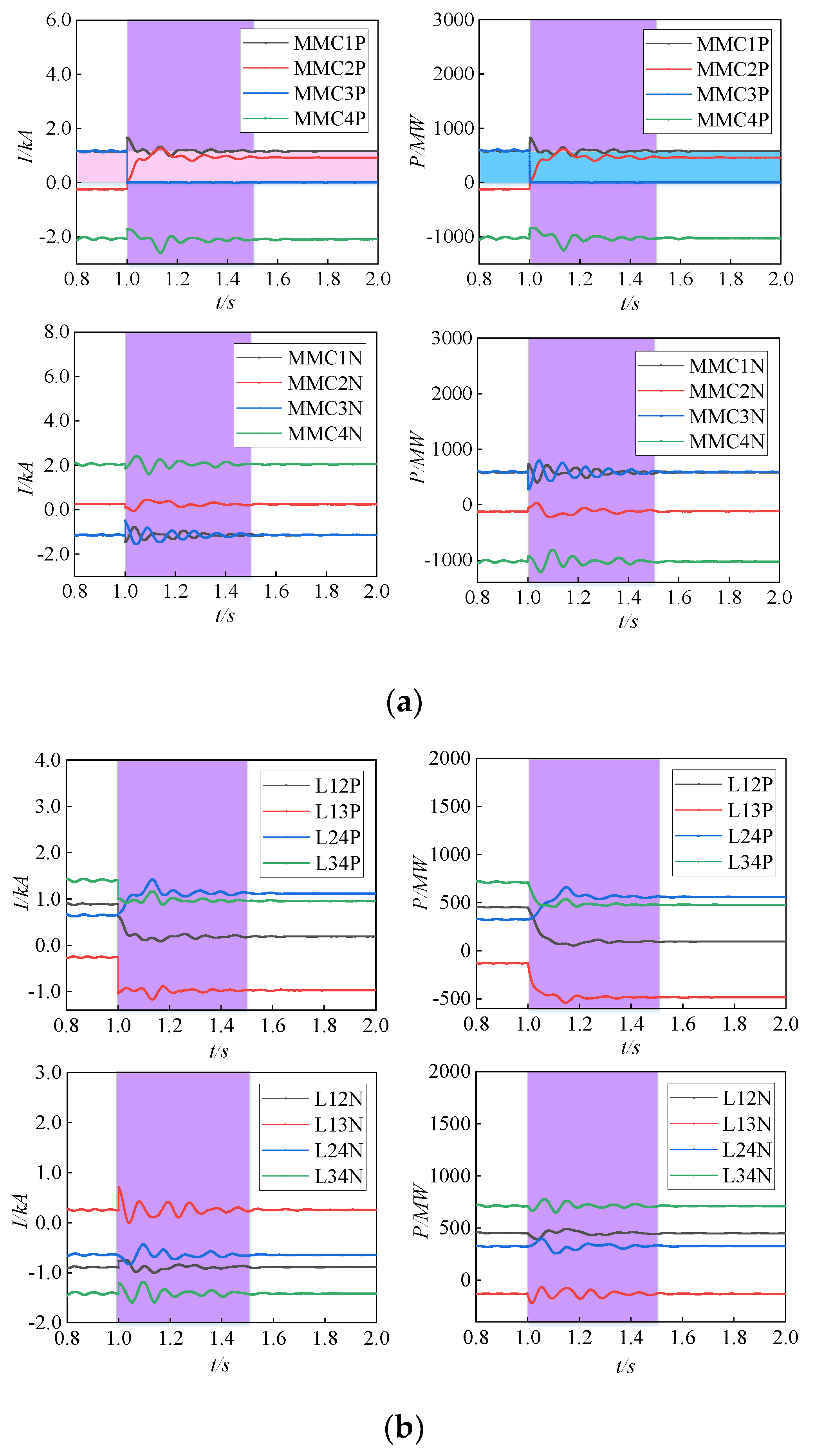
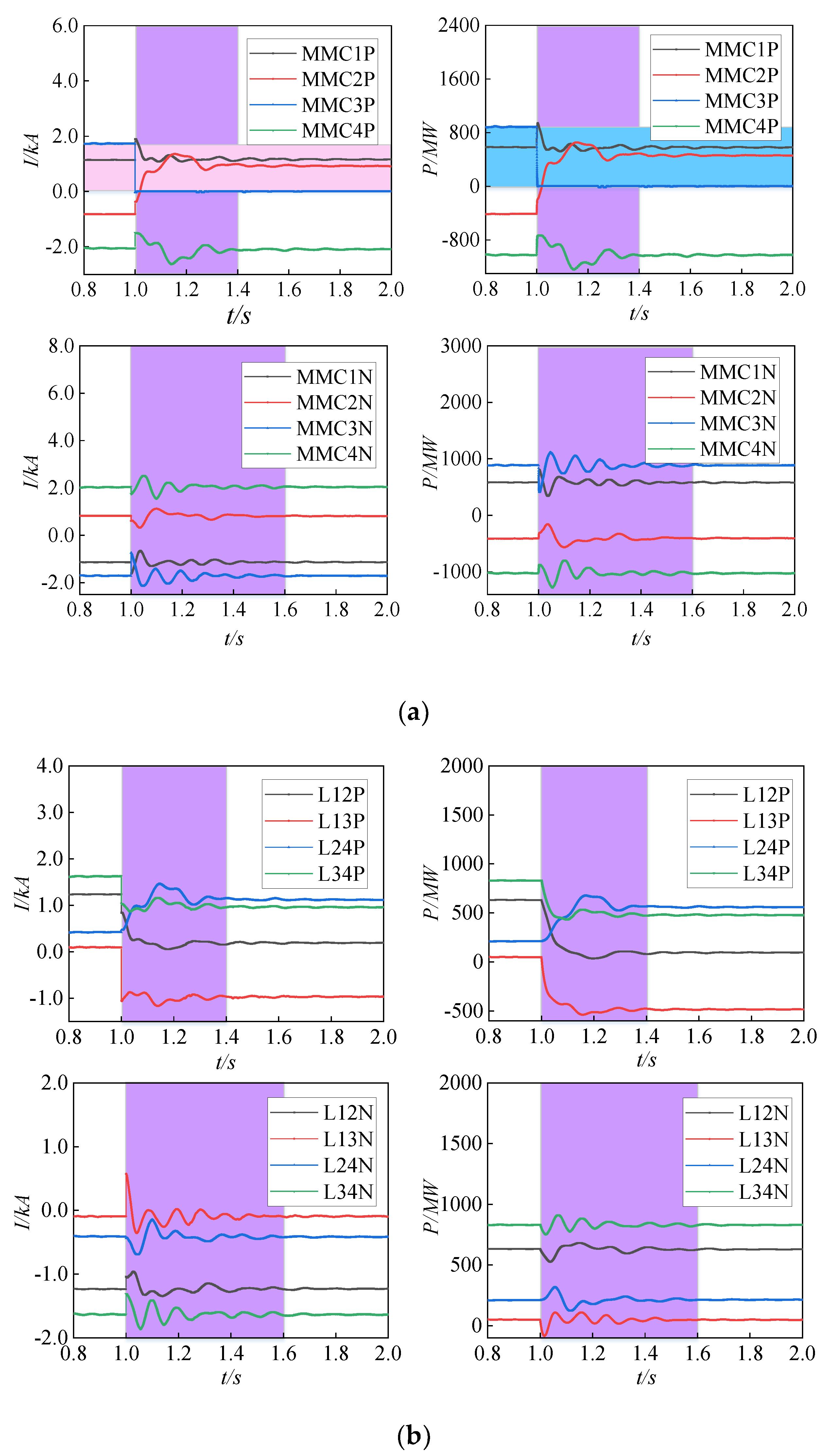
The system characteristics with no power transfer control strategy under the fault condition of DC line are shown in Figure 3. After the fault occurs, if the fault line is overloaded, the system needs to adopt the power transfer control strategy. The system characteristics with power transfer control strategy under the fault condition of DC line are shown in Figure 4.

Figure 3.
(a) Converter station characteristics of a system with no power transfer control strategy under DC line fault condition; (b) DC line characteristics of a system with no power transfer control strategy under DC line fault condition.
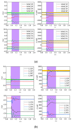
Figure 4.
(a) Converter station characteristics of a system with a power transfer control strategy under DC line fault condition; (b) DC line characteristics of a system with s power transfer control strategy under DC line fault condition.
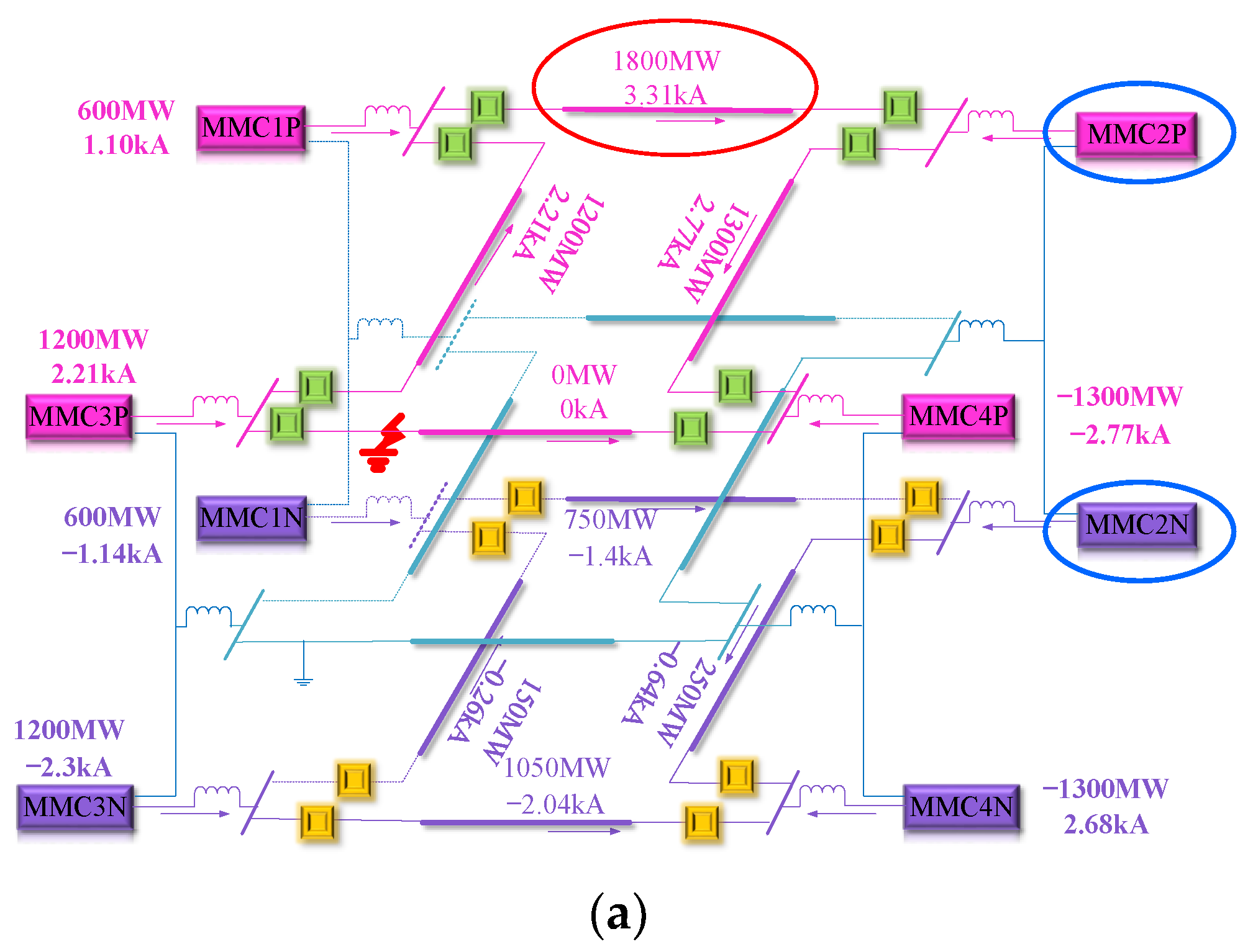
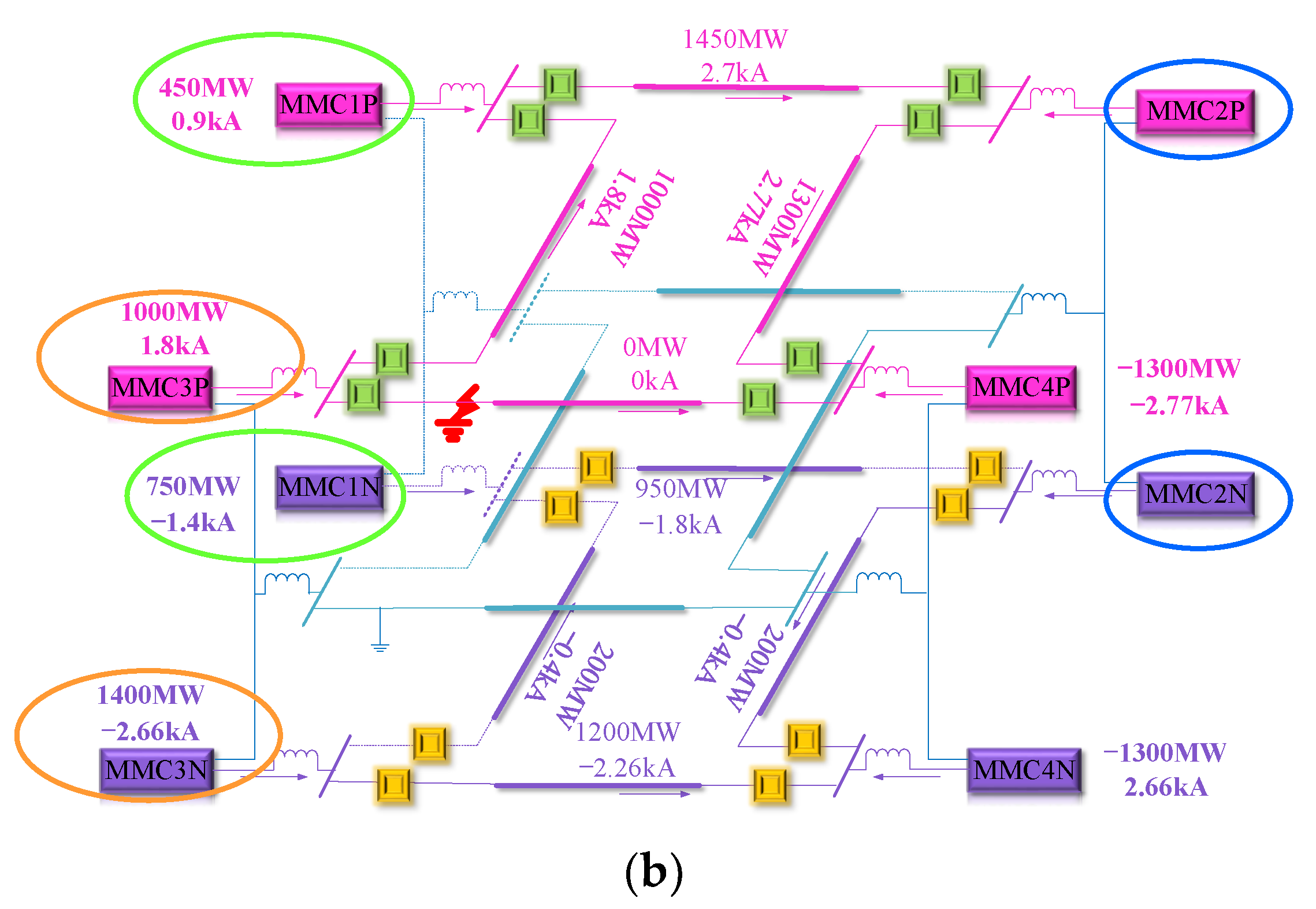
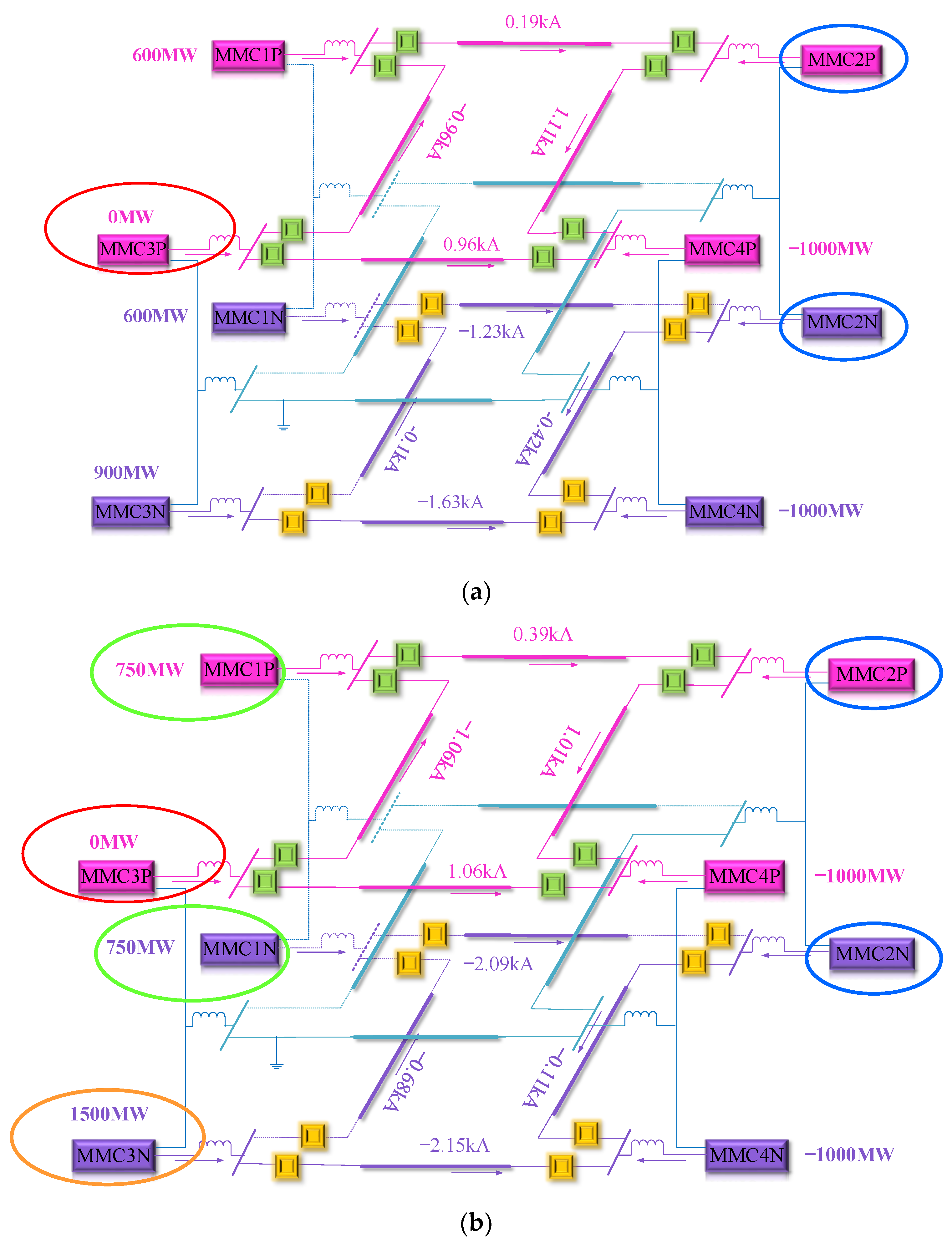
Figure 3 shows that the DC circuit breaker acts on the fault line L34P after the 1.0 s fault, resulting in overcurrent and overload of the non-fault line L12P. From Figure 4 it can be seen that the power transfer control strategy effectively solves the problems of overcurrent and overload of non-fault lines. The power distribution of the system is plotted, as shown in Figure 5. The L12P current is 3.31 kA and the transmission power is 1800 MW, while the rated current of the dc circuit breaker is 3.0 kA. Considering the carrying capacity is 1.05 times and the current capacity is 3.15 kA, the overcurrent of the L12P line will lead to the misoperation of the DC circuit breaker. According to the power transfer control strategy, , MMC1P is 450 MW, MMC1N is 750 MW. , MMC3P is 1000 MW, MMC3N is 1400 MW. After power transfer, the current through L12P is 2.7 kA and the transmission power is 1450 MW.
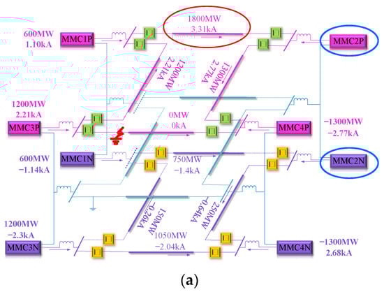
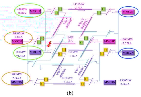
Figure 5.
(a) Power distribution of system without power transfer control strategy under line fault condition; (b) power distribution of system with power transfer control strategy under line fault condition.
4.2. Fault Simulation of Converter Station
When a pole of the converter station at the sending end is locked, and the power loss does not exceed the power margin of the non-fault pole, the non-fault pole to the power transfer is the same as the conventional DC power transfer strategy. If the power margin of the opposite pole is exceeded, the extra part will be transferred of another converter station at the sending end.
4.2.1. Simulation Analysis of Inter-Pole Power Transfer
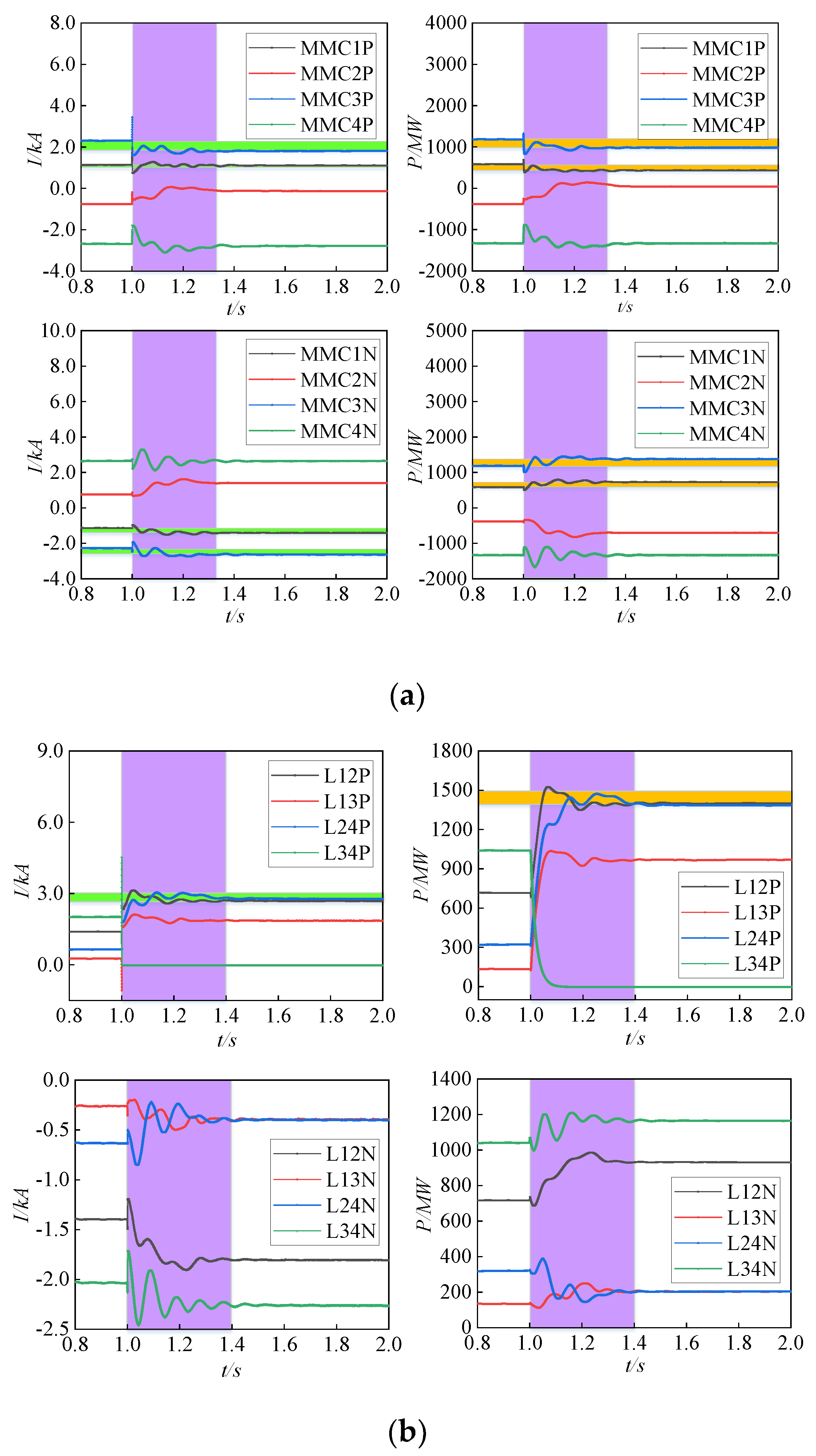
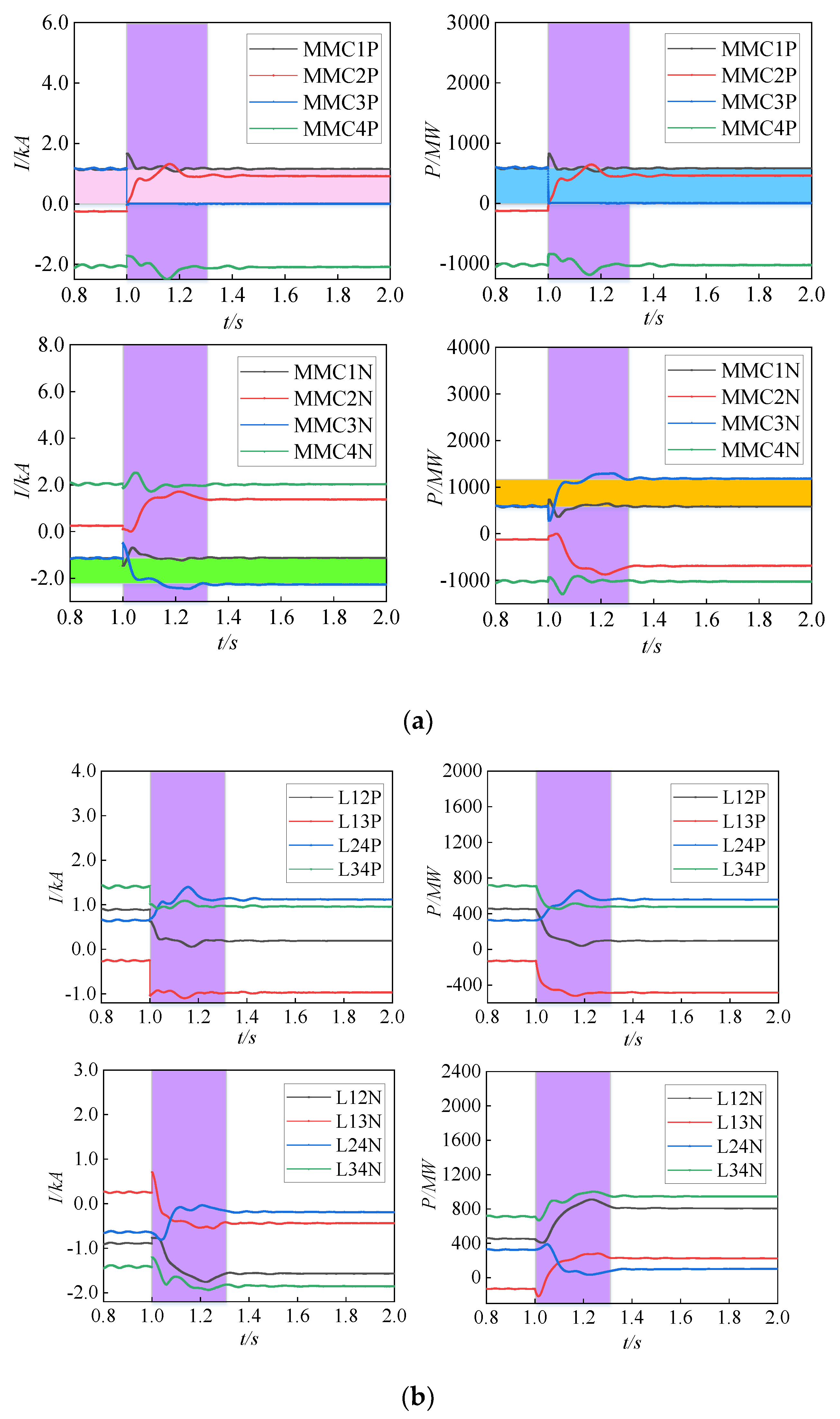
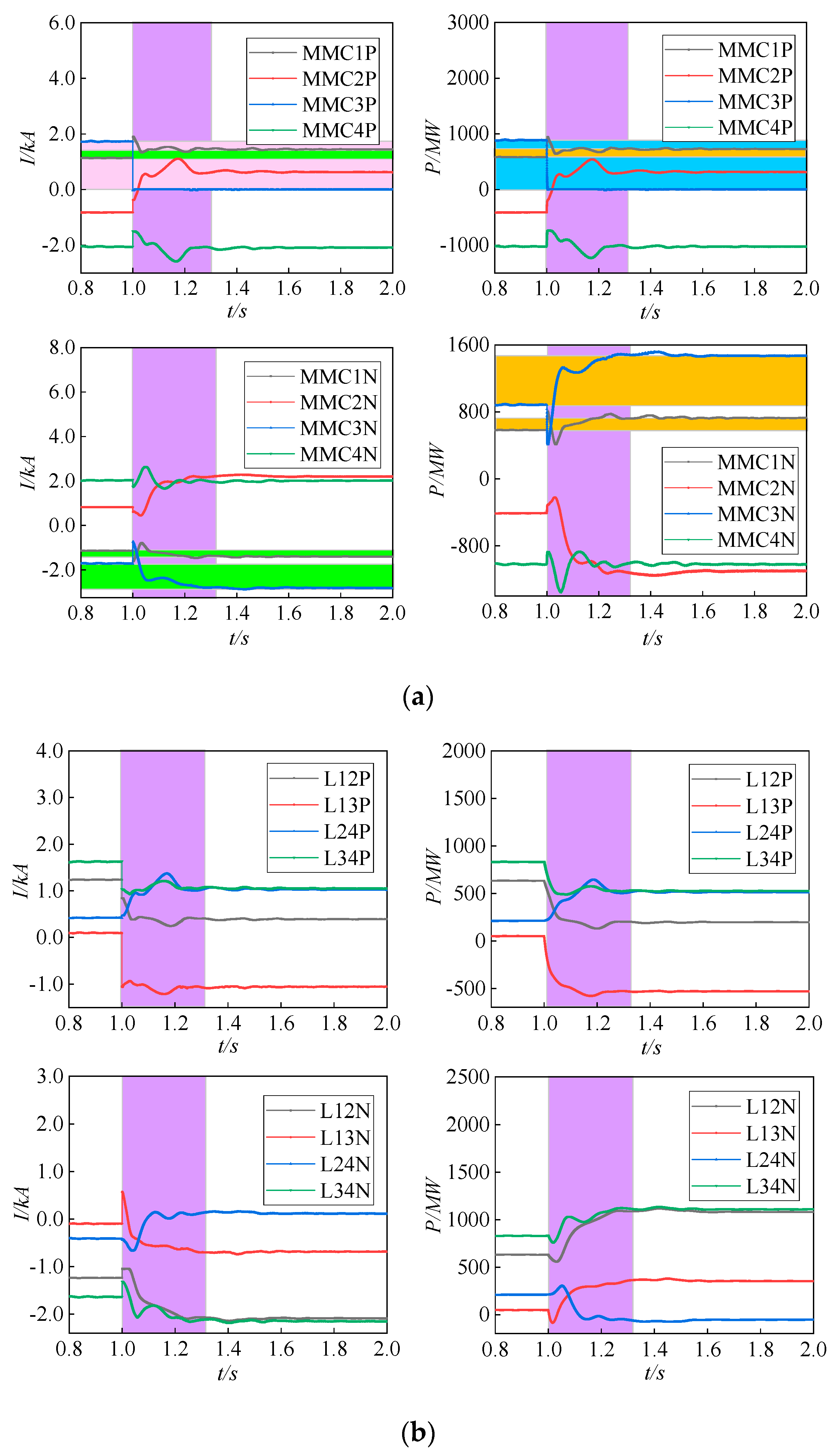
The initial power reference value of MMC1 converter station, MMC3 converter station, and MMC4 converter station are set as 1200 MW, 1200 MW, −2000 MW, and MMC2 converter station as the balance station to stabilize the DC voltage of the whole network. Under normal conditions, the total power of the converter station is equally distributed between the upper and lower poles, so the initial power reference values of a single converter station on the upper pole, MMC1P, MMC3P, and MMC4P, are 600 MW, 600 MW, and −1000 MW respectively. Similarly, the initial power reference values of MMC1N, MMC3N, and MMC4N of a single converter station at the lower pole are 600 MW, 600 MW, and −1000 MW respectively. Table 1 shows the rated power of each converter station, and the power margin of each converter station can be obtained. Set the fault to MMC3P lock, and the fault occurs at 1.0 s. The system characteristics without inter-pole power transfer control strategy under converter station fault condition in Figure 6. After the fault occurs, since MMC3 is bipolar control and MMC3N power margin can fully bear the power transmission of MMC3P, the system can adopt inter-pole power transfer control strategy. The system characteristics with inter-pole power transfer control strategy under converter station fault condition are shown in Figure 7.
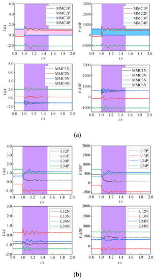
Figure 6.
(a) Converter station characteristics of a system without inter-pole power transfer control strategy under converter station fault condition; (b) DC line characteristics of the system without inter-pole power transfer control strategy under converter station fault condition.
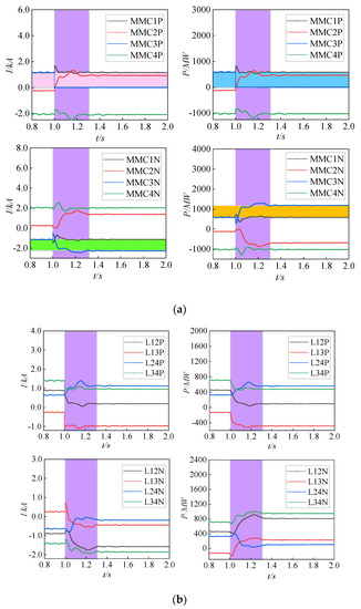
Figure 7.
(a) Converter station characteristics of a system with inter-pole power transfer control strategy under converter station fault condition; (b) DC line characteristics of the system with inter-pole power transfer control strategy under converter station fault condition.
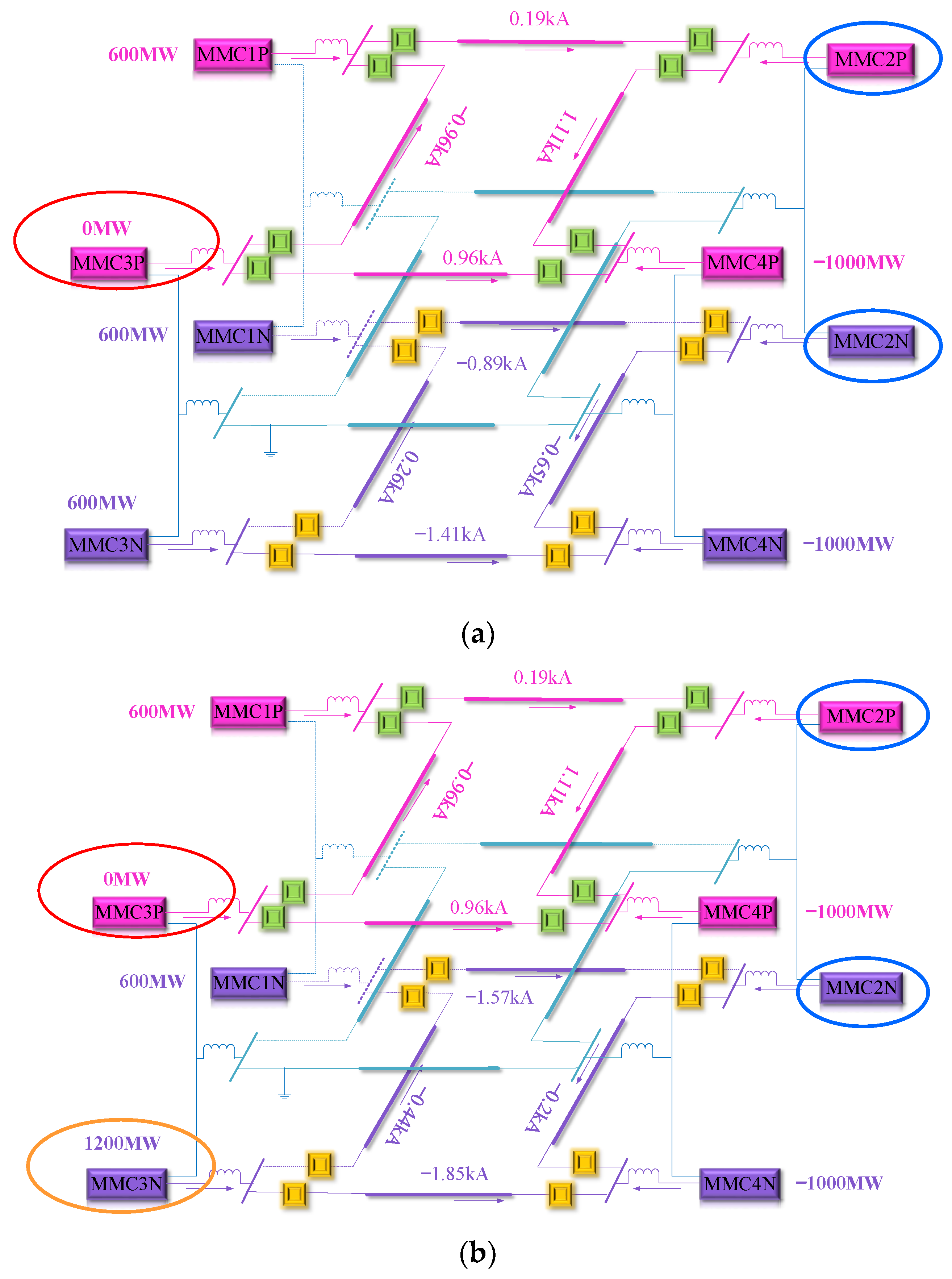
As can be seen from Figure 6, MMC3P was locked at 1.0 s. After the fault, the power value of MMC3P decreases rapidly to 0MW. MMC2P as a balance station, the power of MMC2P is adjusted to stabilize the DC voltage of the system. Because the fault current can pass through the metal loop to form the current loop, the lower pole loop network is affected by the coupling of the upper pole and other factors, and the normal operation state of the loop network is restored at 1.5 s. Figure 7 shows that the HVDC transmission system enters the stable operation state in 1.3 s after the power transfer, which improves the speed of the system transition to the stable state and effectively ensures the power consumption, and improves the power transmission capacity. The power distribution of the system is plotted, as shown in Figure 8, the power value of MMC3P rapidly decreases to 0 MW after the fault. Since MMC3N is bipolar controlled, the power value increases from 600 MW to 1200 MW.
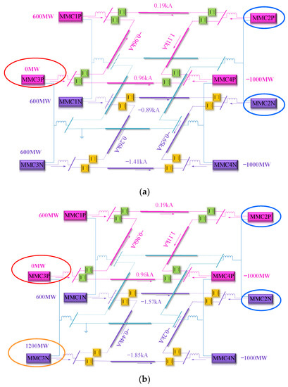
Figure 8.
(a) Power distribution of the system without inter-pole power transfer control strategy under the fault condition; (b) power distribution of the system with inter-pole power transfer control strategy under the fault condition.
4.2.2. Simulation Analysis of Inter-Station Power Transfer
The initial power reference value of MMC1 converter station is set as 1200 mW, the initial power reference value of MMC3 converter station is set as 1800 mW, the initial power reference value of MMC4 converter station is set as 2000 mW, and the MMC2 converter station is set as the balance station to stabilize the DC voltage of the whole network. Under normal circumstances, the total power of the converter station is evenly distributed between the upper and lower poles, so the initial power reference values of a single converter station MMC1N, MMC3N, and MMC4N at the upper pole are 600 MW, 900 MW, and −1000 MW, respectively. The initial power reference values of MMC1N, MMC3N, and MMC4N of single converter stations at the lower pole are 600 mW, 900 mW, and −1000 mW respectively. Table 1 shows the rated power of each converter station, and the power margin of each converter station can be obtained. Set the fault to MMC3P lock, and the fault occurs at 1.0 s. The system characteristics without inter-station power transfer control strategy under converter station fault condition are shown in Figure 9. After the fault occurs, according to the priority of power transfer, the power loss cannot be fully compensated between the poles, and the power loss is compensated between the transfer stations. The system characteristics with inter-station power transfer control strategy under converter station fault condition are shown in Figure 10.
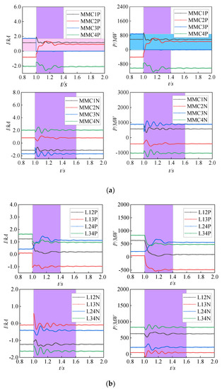
Figure 9.
(a) Converter station characteristics of a system without inter-station power transfer control strategy under converter station fault condition; (b) DC line characteristics of the system without inter-station power transfer control strategy under converter station fault condition.
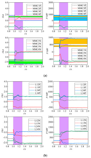
Figure 10.
(a) Converter station characteristics of a system with inter- station power transfer control strategy under converter station fault condition; (b) DC line characteristics of the system with inter-station power transfer control strategy under converter station fault condition.
As can be seen from Figure 9, MMC3P was locked at 1.0 s. MMC3P output power and DC current instantaneous drop to 0 MW. MMC2P is used as a balance station to adjust the balance of the upper pole ring network system. The lower pole ring network is affected by the upper pole fault and produces slight fluctuations. After 1.6 s, there is no shock and the system resumes normal operation. Figure 10 shows that the control strategy of inter-station power transfer can effectively prevent the sending end from tripping generator, improve the absorption capacity of the power grid, the stability and reliability of the system. After 1.2 s, the system has no shock and returns to stable operation, accelerating the speed of the system’s transition to a stable state. The power distribution of the system is plotted, as shown in Figure 11. As can be seen from Figure 11, considering that the capacity of MMC3N is 1500 MW, it cannot undertake the total power of 1800 MW emitted by MMC3, while the sending MMC1 can undertake the remaining 300 MW, so the power instruction of MMC3N is 1500 MW, and the upper and lower poles of MMC1 are both 750 MW.
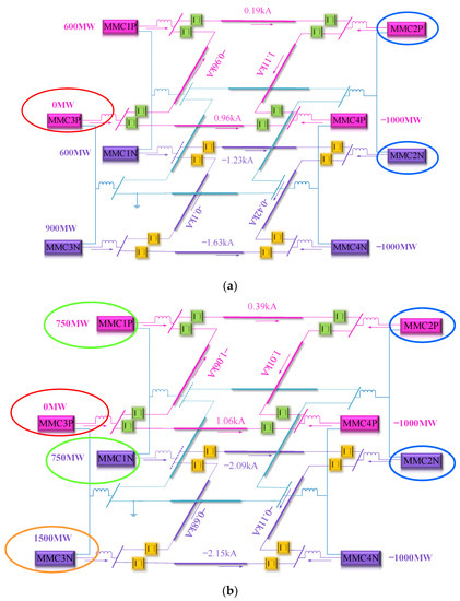
Figure 11.
(a) Power distribution of the system without inter- station power transfer control strategy under the fault condition; (b) power distribution of the system with inter-station power transfer control strategy under the fault condition.
5. Conclusions
In this paper, the application conditions of power transfer control strategy for true bipolar MMC-MTDC system are summarized, and a widely applicable power transfer control strategy is proposed on the basis of previous studies. In the PSCAD/EMTDC, Zhangbei four-terminal ±500 kV flexible HVDC transmission system was built to simulate and verify the power transfer control strategy. The following conclusions can be drawn:
- In the case of single-pole line fault, considering the two factors of line transmission power margin and the power margin of converter station’s power transfer, the power reference value of converter station at the sending end can be adjusted cooperatively to transfer the overloaded power of fault pole to the non-fault pole effectively, so that both the upper and lower poles can operate normally and stably.
- In the case of converter station fault, considering that the inter-pole power transfer is preferred to the inter-station power transfer, the power transmission capacity of the system can be effectively improved, and the system generator tripping and load shedding can be reduced. To a certain extent, the transition of the system to a stable state is accelerated, and the stability of the system is improved.
- In the true bipolar MMC-MTDC system, the priority of the power margin of the converter station should be considered when carrying out inter-station power transfer. The converter station with large power margin has the priority to carry out power transfer, which can reduce the participation of the converter station and improve the reliability of the system.
Author Contributions
Conceptualization, C.D., X.T., T.N. and Z.Y.; methodology, C.D. and X.T.; software, X.T. and T.N.; validation, C.D., X.T., T.N. and Z.Y.; formal analysis, X.T.; writing—original draft preparation, C.D., X.T., T.N. and Z.Y.; writing—review and editing, C.D., X.T., T.N. and Z.Y. All authors have read and agreed to the published version of the manuscript.
Funding
This research received no external funding.
Institutional Review Board Statement
Not applicable.
Informed Consent Statement
Not applicable.
Data Availability Statement
The study did not report any data.
Acknowledgments
Thanks to the State Key Laboratory of Advanced Electromagnetic Engineering and New Technology, Huazhong University of Science and Technology.
Conflicts of Interest
The authors declare no conflict of interest. The funders had no role in the design of the study; in the collection, analyses, or interpretation of data; in the writing of the manuscript, or in the decision to publish the results.
References
- Xing, C.D. Design of neutron module controller for MMC control system. Power Syst. Prot. Control. 2016, 44, 114–121. (In Chinese) [Google Scholar]
- Yang, S.; Xiang, W.; Yang, R.Z.; He, Y.J.; Wen, J.Y. Research on adaptive reclosing technology for the half-bridge MMC and hybrid DC circuit breaker based on HVDC systems. Proc. CSEE 2020, 40, 4440–4451. (In Chinese) [Google Scholar]
- Jiang, C.B.; Yu, Y.J.; Wang, X.; Zhao, C.Y. Fault current active transfer MMC for DC power grid. Power Syst. Technol. 2021, 45, 170–178. (In Chinese) [Google Scholar]
- Li, G.; Liu, X.; Zhang, S.; Jiang, T.; Chen, H.; Li, X. Calculation method of short-circuit fault current at TWBS-HVDC side based on MMC. Autom. Electric Power Syst. 2020, 44, 91–100. (In Chinese) [Google Scholar]
- Lv, J.; Wu, Z.; Dou, X.; Chen, Q.; Yang, J.; Xiao, X. Protection strategy of inter-pole short-circuit fault in medium-voltage DC distribution network based on MMC. Electr. Power Eng. Technol. 2019, 39, 43–50. (In Chinese) [Google Scholar]
- Wang, H. VSG based control technology of HVDC inverter side MMC. J. Chang. Inst. Technol. 2019, 33, 52–56. (In Chinese) [Google Scholar]
- Tang, G.F. HVDC Transmission Technology Based on Voltage Source Converter; Electric Power Press: Beijing, China, 2010. (In Chinese) [Google Scholar]
- Liu, B. Research on Coordinated Control Strategy of Multi-Terminal Flexible HVDC Transmission System; Anhui University of Science and Technology: Huainan, China, 2019. (In Chinese) [Google Scholar]
- Ding, J.J. Research on Control Strategy and Stability of MMC-MTDC System; Lanzhou University of Technology: Lanzhou, China, 2019. (In Chinese) [Google Scholar]
- Abedin, T.; Lipu, M.; Hannan, M.A.; Ker, P.J.; Rahman, S.A.; Yaw, C.T.; Muttaqi, K.M. Dynamic modeling of hvdc for power system stability assessment: A review, issues, and recommendations. Energies 2021, 14, 4829. [Google Scholar] [CrossRef]
- He, Y.; Zhou, L.; Li, Y.; Gu, W.; Zhao, B.; Wang, S. Power conversion strategy of VSC-MTDC system based on real bipolar wiring mode. Autom. Electr. Power Syst. 2017, 41, 95–101. (In Chinese) [Google Scholar]
- Li, Y.B. The Fault Characteristics and Control Strategies of MMC-Based HVDC Grid; China Electric Power Research Institute: Beijing, China, 2017. (In Chinese) [Google Scholar]
- Li, C.; Hu, W.W.; Tang, Z.J. Control strategy of power transfer in bipolar HVDC flexible transmission system. High Volt. Technol. 2018, 44, 2173–2180. (In Chinese) [Google Scholar]
- Wang, S.; Liu, T.; Li, B.; Yu, Y. Analysis on characteristic of DC network line breakage fault and a control-based protection strategy. Sci. Technol. Eng. 2019, 19, 201–207. (In Chinese) [Google Scholar]
- Wen, H.Z. Research on Emergency Coordinated Control Strategy of Modular Multilevel Converter Based HVDC Grids; Guangxi University: Nanjing, China, 2020. (In Chinese) [Google Scholar]
- Yu, X.; Wang, Y.Z.; Zhang, Q.; Wang, Y.; Dong, Y.; Gan, Z. Power transfer strategy of parallel three-terminal hybrid UHVDC transmission system. Autom. Electr. Power Syst. 2020, 44, 150–156. (In Chinese) [Google Scholar]
- Uddin, W.; Busarello, T.D.C.; Zeb, K.; Khan, M.A.; Yedluri, A.K.; Kim, H.-J. Control Strategy Based on Arm-Level Control for Output and Circulating Current of MMC in Stationary Reference Frame. Energies 2021, 14, 4160. [Google Scholar] [CrossRef]
Publisher’s Note: MDPI stays neutral with regard to jurisdictional claims in published maps and institutional affiliations. |
© 2021 by the authors. Licensee MDPI, Basel, Switzerland. This article is an open access article distributed under the terms and conditions of the Creative Commons Attribution (CC BY) license (https://creativecommons.org/licenses/by/4.0/).