1. Introduction
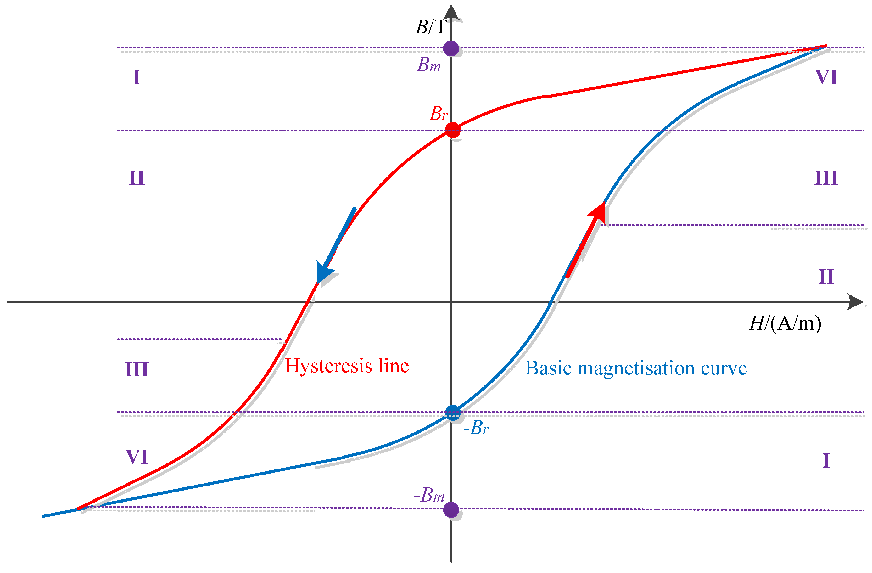
When a power transformer is cut out of the system, a certain amount of residual flux will be generated due to the hysteresis characteristics of the core material. The residual flux will have a large impact on the stable operation of the transformer when the transformer is reclosed. The inrush current can be 6–10 times the rated current when electromagnetic transients occur in the reclosing process of the power transformer. Therefore, accurate measurement of the residual flux of the core is of great significance for analyzing the electromechanical characteristics of the winding under the inrush current.
To detect the residual flux in the transformer core, many algorithms and models have been proposed by domestic and foreign researchers. For example, Ref. [
1] used the change in the permeability of local hysteresis lines to calculate the residual flux, but its calculation method is too complicated for application in engineering practice. Ref. [
2] proposed a method for calculating the residual flux considering the transient magnetization current, and derived an empirical formula for the calculation of the residual flux magnetic density, the error of which can always be less than 10%. However, this method cannot determine the direction of the residual flux. Refs. [
3,
4] proposed a residual flux measurement method by establishing a known relationship between the residual flux and the current of a power transformer. They built a core detection circuit for ring transformers, processes the experiments to obtain transient measurement current signals, and substituted the results into the residual flux and current relationship equation. This method was able to obtain the residual flux in the core of power transformers more accurately.
For more results, many researchers have started their research from the perspective considering the residual flux’s direction. For example, Ref. [
5] proposed a residual flux measurement method considering the residual flux direction. The transient current of the coil under different voltages and residual flux densities was analyzed by means of both the principle calculation and simulation analysis, and an empirical formula for the residual flux was obtained. Finally, the results were verified by experiments. A method for interpreting the residual flux of a single-phase transformer by sequentially applying two Direct Current (DC) voltages of opposite polarity to the transformer windings and then detecting their corresponding transient response currents was proposed in [
6]. The equation between the residual flux and the transient current difference was fitted using the data analysis method. Finally, the effectiveness of the method was verified through experiment. Although the above methods are able calculate the residual flux’s value in the transformer core, they are difficult to implement in practice.
Excessive inrush current in the windings can seriously affect the electromechanical characteristics of the transformer, which may even in serious cases lead to the destruction of the transformer. Refs. [
7,
8] analyzed the electromagnetic forces generated by inrush currents and the impact they have on the transformer structure. Mechanical failures of the transformer usually manifest as the deformation and the displacement of the windings. When the deformation and displacement of the windings exceeds the threshold value, plastic deformation occurs, and the insulation capacity is gradually reduced. Furthermore, the failure resistance of the transformer is significantly reduced.
To analyze the effects of excessive inrush currents on transformers, structural optimization and simulation methods for analyzing magnetic fields of transformers have emerged. One of the most widely used computational analysis methods for electromagnetic as well as the structural simulation is the finite element method. Residual flux in the core could produce an inrush current which amplitude can far exceed the rated current. For example, in [
9], a numerical analysis method was proposed to accurately calculate the inrush current of a three-phase three-arm core transformer considering the nonlinear magnetization curve of the iron core. Ref. [
10] used Octave software to calculate the maximum value of the inrush current generated by a single-phase transformer. Meanwhile, the magnetic density, air-gap leakage, and winding losses of the transformer core under the maximum inrush current were analyzed using finite element simulation analysis. In Ref. [
11], a method for calculating the inrush current of superconducting transformers was proposed, and the accuracy of the calculation results was verified by experiments. Refs. [
12,
13,
14,
15] analyzed the transient electromagnetic forces of large power transformer windings under short-circuit currents. A three-dimensional transformer electromagnetic-structural coupling finite element model was established to analyze the dynamic electromagnetic force and winding mechanical structure interaction during short-circuit condition, and the simulation analysis results were compared with the experimental results. Ref. [
16] qualitatively and quantitatively analyzed the mechanical power generated in the transformer winding under the action of inrush current by means of analytical and numerical methods. The analytical and computational results were compared and analyzed with the experimental results, which proved the validity of the method and the correctness of the conclusions. A method based on digital image processing of transformer winding deformation was proposed in Ref. [
17]. Ref. [
18] detected and classified different operating conditions of transformers by building a neural network classification model. The above studies focus on the deformation of transformer windings under excitation current and the ability of windings to resist fault current, with fewer studies examining the combined variation of the transformers under inrush current, with no clear conclusions being given.
Both the short-circuit current and the inrush current have a great impact on the transformer, and in some cases, the inrush current on the transformer winding can even produce a greater impact than the short-circuit current. Ref. [
8] analyzed the short-circuit forces on the windings of a 50 KVA, dry-type transformer under short-circuit current using finite elements and verified the correctness of the simulation analysis by experiments. In Ref. [
19], a single-phase, 50 MVA transformer model was established, and the model was analyzed using the finite element method to analyze the axial and radial forces on the transformer windings under the inrush current. In Ref. [
20], the electromechanical stresses generated in the transformer windings by the inrush current and short-circuit current were studied by means of both numerical calculations and simulation analysis. In Ref. [
21], the radial short-circuit forces generated on the transformer’s low-voltage (LV) winding under short-circuit were studied. The relationship between the leakage flux in the transformer windings and the short-circuit electromagnetic force was analyzed. The radial short-circuit forces were calculated, and the ability of the LV winding to withstand short-circuit currents was evaluated according to International Electrotechnical Commission (IEC) standards and short-circuit experiments. Ref. [
22] used the electromagnetic-thermal-fluid coupling method to analyze the effects of inrush currents on transformer windings. Ref. [
23] used the field-circuit coupling method to calculate the leakage magnetic field and the short-circuit electromagnetic force under short-circuit conditions. According to the actual parameters, the flexural of the windings was analyzed to study the axial stability of the windings. In Ref. [
24], the field-circuit coupling method was used to compare the leakage and the electromagnetic forces of transformer low-voltage windings under different short-circuit conditions. In Ref. [
25], a simulation model of transformer winding loosening, winding deformation and winding insulation failure was developed using a simulation model of a transformer in normal operation, and the vibration characteristics of winding faults were analyzed. The above-mentioned studies mainly focus on the analysis of the impact of short-circuit current on transformer windings from a structural perspective. Studies on the effect of the electromagnetic transients generated by the inrush current on the electromechanical characteristics of the transformer are fewer, and most of the conclusions are vague, while at the same time lacking experimental verification.
With increasing transformer capacity, the impact of the inrush current on the transformer becomes more and more significant. In particular, in the case of no-load reclosing, the impact of inrush current on the transformer is more prominent. In this case, the analysis of the inrush current during the no-load reclosing transient, as well as the electromechanical characteristics of the windings under the inrush current, are of great importance, and may extend the lifetime of the transformer and allow the diagnosis of transformer fault. Therefore, this paper provides a comprehensive analysis of the transformer magnetic field changes and leakage flux distribution at the moment of transformer reclosing. At the same time, the electromagnetic-structural field coupling method is used to analyze the impact of the inrush current by the transformer re-closing condition.
Inrush current is generated at the instant of no-load reclosing of the transformer, and is mainly a result of the closing phase angle and residual flux. Currently, most of the research on residual flux is focused on measurement and suppression, and most of the methods are difficult to implement in operating transformers. Therefore, this paper uses the phase-controlled switching technique to control and calculate the residual fluxes of the transformer core under different closing phase angles, as well as to analyze the peak excitation inrush currents and their effect on the transformer windings generated under different residual fluxes.
In summary, this paper presents a comprehensive analysis of the electromechanical characteristic of power transformer windings with different residual fluxes and reclosing angles. Firstly, a simulation circuit of the power transformer is established to analyze and obtain the inrush current under the no-load reclosing condition of the transformer with different residual fluxes. Secondly, the “field-path” coupling method and finite element method are combined to analyze the electromagnetic force of the transformer winding under the inrush current corresponding to different residual fluxes. After that, the power transformer electromagnetic-structural coupling analysis model is established to analyze the deformation of the winding structure. Then, based on the simulation results, the parametric relationships between residual flux and closing phase angle and electromagnetic force and winding deformation are obtained. Finally, the validity of the simulation method and the correctness of the results are verified by experiments.
3. Generation and Calculation of Excitation Inrush Current
The transformer needs to go through a transient process after reclosing before it can reach a steady state, i.e., the decay process of the excitation current. Equation (3) shows the relationship between voltage, current and flux in a transformer.
where
Vm is the peak voltage (V),
θ is the voltage switching angle when the transformer is closed (°),
i0(
t) is the instantaneous current generated at the time of reclosing (A),
ϕm(
t) is the instantaneous flux which contains the main flux and the leakage flux (Wb),
R is the resistance of the windings in the transformer (Ω).
Equation (4) is the value of the instantaneous flux when the transformer is energized instantaneously.
where the peak value of the steady-state flux of
ϕp (Wb),
ϕr is the value of the residual flux (Wb),
L is the inductance of the excitation coil (H).
When
θ = 0° and the
ϕr of the residual flux is positive, the flux waveform is shown in
Figure 2.
From
Figure 2, the magnetic flux
ϕ in the transformer core is kept at a low level when the residual flux equals to zero. When residual flux is present, the initial value of the magnetic flux in the core will be increased, which makes it easier to saturate the core.
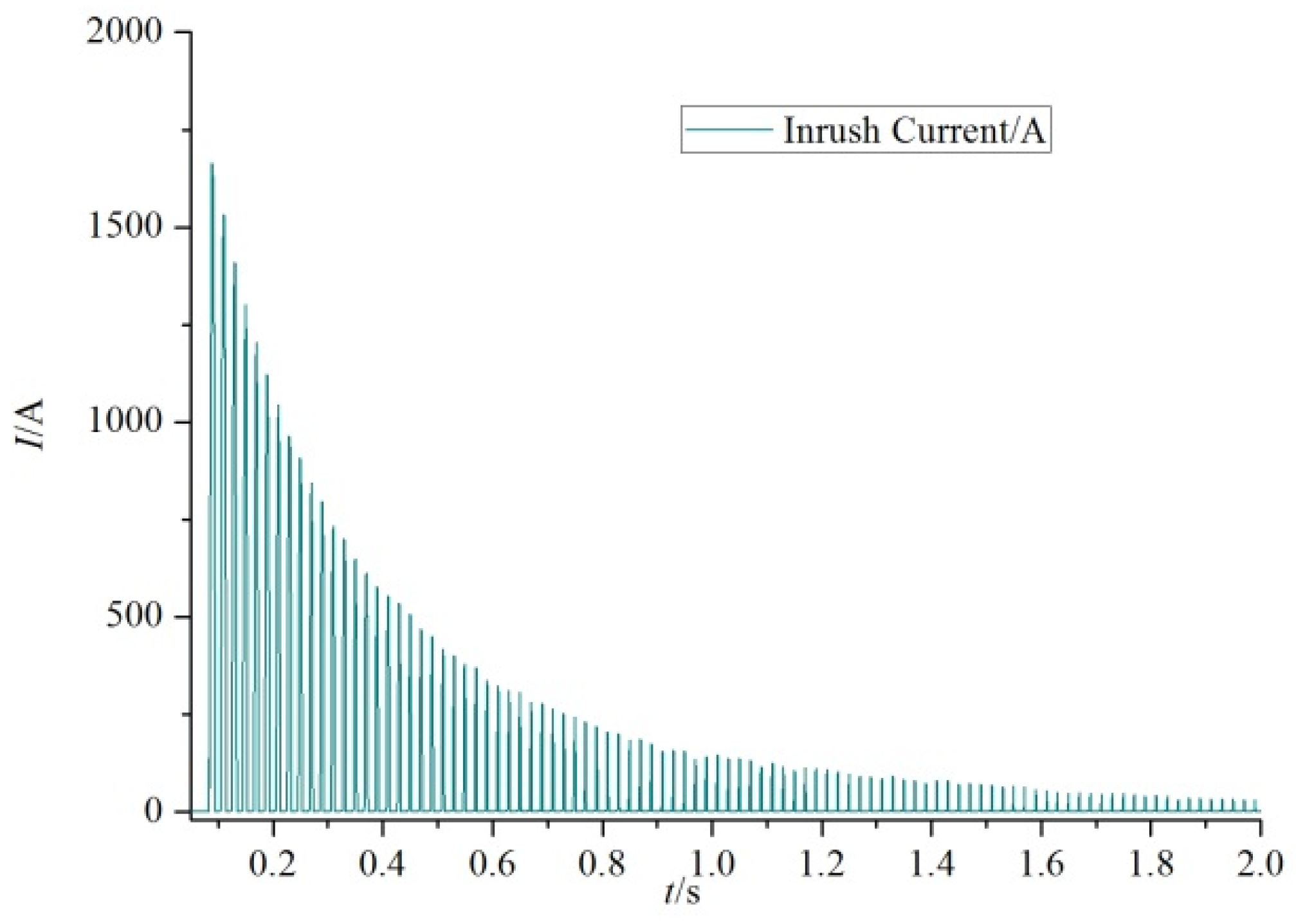
Figure 3 shows a typical inrush current waveform at the moment of transformer energization.
When calculating the peak inrush current, it is first necessary to determine the saturation flux in the core, which can be determined by Equation (5).
where
S is the cross-sectional area of the iron core (cm
2).
The leakage flux
ϕair in the air gap can be calculated by Equation (6) (Wb).
where
H is the magnetic field strength (A/m).
Equation (7) is the average cross-sectional area of the coil winding
Sm.
where
Dm average winding diameter (m).
In the case of magnetic saturation of the iron core, the system reactance value
Xs can be calculated by Equation (8).
where
μ0 is the air magnetic permeability (H/m).
f is the power supply frequency (Hz). Equation (9) represents the switching angle.
where
K1 is the saturation angle correction factor.
Bs is the saturation magnetic flux density (T).
Br is the residual flux magnetic flux density (T).
K1,
Bs, and
Br are equal to 0.9, 1.25
Bmp, and 0.8
Bmp.
The peak value of magnetic induction (
Bmp) in the transformer core can be calculated by Equation (10).
where
V is the voltage value when the transformer is operating (V).
Score is the cross-sectional area of the iron core.
According to the formula derived from our previous study [
26], Equation (11) is used for calculating the peak inrush current.
where
i0max is the peak inrush current generated by the single-phase transformer (A).
K2 is the peak inrush current correction factor, whose value is 1.15.
7. Discussion
Table 2 shows the comparison of the simulated value
Imax1 and the experimental value
Imax2 of the peak inrush current generated by the transformer under different residual fluxes
Br when the closing phase angle
θ = 0°.
From
Table 2, it can be seen that the maximum error between the simulated value and the experimental value obtained by simulation is less than 0.3%, and the minimum error is less than 0.1%, demonstrating the effectiveness of the simulation analysis method. At the same time, with the increase of the residual flux
Br, the amplitude of the inrush current gradually increases, compared with zero residual flux, the residual flux
Br increases to 1.24 T when the inrush current amplitude
Imax increases by about 2.5 times.
Table 3 shows the comparison between the simulated value Δ
x1 and the tested value Δ
x2 under different residual fluxes
Br of line 5 cake.
From
Table 3, it can be seen that the maximum error between the simulated value Δ
x1 and the experimental value Δ
x2 obtained by simulation is less than 1%, and the minimum error is less than 0.1%, demonstrating the effectiveness of the simulation. Meanwhile, as the residual flux
Br increases, the winding deformation gradually increases. Compared with zero residual flux, the winding deformation Δ
x increases about 3 times when the residual flux
Br increases to 1.24 T.
Comparison and analysis of the experimental results and the simulation results proved that the different residual fluxes could lead to differences in the peak magnitude of the inrush current, the leakage magnetic field, the winding electromagnetic force, and the deformation of the winding. As the residual flux of the transformer core increases, the inrush current, as well as the winding deformation, increases significantly.
8. Conclusions
In this paper, the electromechanical characteristics of the no-load reclosing winding of a dry-type transformer under different residual fluxes are comprehensively analyzed. First, a simulation circuit was built to obtain the peak inrush current generated during no-load reclosing under different residual fluxes of the transformer core. At the same time, these current peaks are loaded as the excitation into the transformer model. Moreover, the electromechanical characteristics of the transformer winding under the influence of the inrush current generated during no-load reclosing are analyzed using the field-circuit coupling and the finite element method. Finally, for the verification tests, the closing operation of the transformer is controlled by the phase-controlled switch, and the residual flux at the closing moment is calculated based on the analysis of the breaking angle. The laser Doppler vibrometer and the measuring coil were used to measure the winding deformation and air gap leakage. On the basis of a comparative analysis of the experimental and simulation results, it can be seen that as the residual flux in the core increases, under the combined effect of the inrush current and the air gap leakage field, a large electromagnetic force is generated on the transformer winding. According to the simulation and experimental results, the axial electromagnetic force generally affects the winding end more obviously, and the middle position of the winding is more affected by the radial electromagnetic force.
The validity and reliability of the simulation method and the principle analysis are proved in this paper by their comparison. The comprehensive analysis and experimental verification of the electromechanical characteristics of the transformer windings in the case of no-load reclosing were performed in this paper, making it possible to effectively assess the performance of transformer winding parameters under the influence of inrush current. This research can be applied to the simulation analysis of different power transformers, and is a guide for extending the service life of transformers and the in-depth study of transformer fault analysis. With the increase of grid capacity, it is of great significance to the power system to ensure the safe and stable operation of transformers.
However, when transformers are subjected to multiple inrush current shocks in a relatively short period, their electromechanical characteristics are bound to be greatly affected. Therefore, in the next step, it is necessary to analyze the electromechanical characteristics of a transformer when it experiences multiple inrush currents.


