1. Introduction
Wave energy has long been recognised as having the potential to significantly contribute to global energy transition as an abundant and renewable energy source [
1]. However, it is challenging to develop commercially viable devices that harness energy from ocean waves. These devices must be fully functional and cost-effective to deploy, and at the same time, be able to withstand extreme environmental conditions, capture wave energy efficiently in various sea conditions, and be easy to deploy, recover and maintain. Hence, there is an urgent need for the technology to become cost competitive with more traditional energy sources if it is to be included in the energy mix. Radical innovation at the earliest stages of technology design can enable a step-change in cost reduction of wave energy technology [
2].
However, there are many competing wave energy converter (WEC) designs [
3]. Consequently, initiatives have been launched that aim to achieve design consensus and accelerate development by providing structure to the innovation process in order to enable the step change in cost. An example of this is the Wave Energy Prize competition in 2016, an 18-month public design, build and test competition sponsored by the U.S. Department of Energy (DOE) Water Power Technologies Office that saw wave energy technologies compete to provide a winning design [
4].
Another approach, which has been running since 2014, is the Wave Energy Scotland (WES) stage gate programme [
5], in which participating developers compete to be awarded funding by satisfying key economic and performance criteria. The number of projects is reduced at each stage of funding, so the most promising technologies receive maximum investment. Through this programme, two wave energy technologies are currently being demonstrated at half-scale in open water testing and will move towards commercial-scale and deployment in the first commercial arrays in the future.
Whilst this programme has been instrumental in building confidence in the sector and holds further opportunity for cost reduction through innovation and economies of scale, WES, through the SEAWEED project, is seeking to identify and enable better technology development in the wave energy sector by developing a structured approach to wave energy concept creation. The developed scenario creation tool will add structure to the initial phase of wave energy innovation, whereby concepts are created based on their potential to be commercially attractive and technically achievable. It has previously been recognised that there is a need for a more objective technology assessment approach at the earliest possible stages of development, despite the high uncertainties [
6]. A structured concept creation approach should also allow for the broadest spectrum of concepts to be considered to avoid a preconceived fixation on certain characteristics and allow for a full exploration of the parameter space.
The DTOceanPlus project, funded by the European Commission’s Horizon 2020 programme, has developed a suite of 2nd generation advanced design tools for the selection, development, and deployment of ocean energy systems. The Scenario Creation tool is a component of DTOceanPlus, addressing the gap in early-stage concept creation by creating “what if?” scenarios for potential WECs by combining key parameters/attributes together into a scenario where variables are treated independently. These hypothetical scenarios are scored for their commercial attractiveness and technical achievability. Finally, scenarios are filtered out if they are unattractive, impossible, or unachievable, based on a comparison to certain thresholds defined in this paper. The links between the scenario variables and these thresholds are created using several fundamental relationships of wave energy. These fundamental relationships are the engineering, physics, and underlying economic relationships that drive the earliest stages of assessing the attractiveness of concepts [
7]. They are established based on available data from the wave energy sector, including data from developers involved in the WES programmes (herein referred to as WES developers), numerical optimisation modelling [
8], and data from other similar sectors.
Potential users of the scenario creation tool include public-sector funding organisations, private investors, and technology developers, for whom the tool can provide a more informed decision-making process. The aim is to stimulate innovation in areas of the parameter space identified as having the highest potential for success.
The remainder of this paper is laid out as follows.
Section 2 provides background on structured innovation tools in the wave energy sector.
Section 3 outlines the methodology for scenario creation along with the methods used to find the thresholds and fundamental relationships.
Section 4 provides example results to demonstrate the capability and potential benefits of both using the tool and its outputs for further analysis. This includes a discussion on how the outputs of the scenario creation tool can lead to interesting avenues of innovation. Finally,
Section 5 outlines the main conclusions of this paper.
2. Review of Other Structured Innovation Tools
Bringing structure to the earliest stages of the innovation process in technology development has been proven effective in mature sectors. Industries such as the aerospace (e.g., Rolls-Royce) and automotive (Ford automotive, Toyota) have put into practice a form of structured approach to create and drive innovative solutions [
7]. Toyota, for instance, introduced structured innovation methods, including Quality Function Deployment (QFD), in their product design and reported a one-third reduction of the product development cycle (time to market) and fewer design changes overall [
9]. This has led to the development of a global methodology for Structured Innovation, described in BS 7000-1 [
10].
However, despite its proven effectiveness in the industry, there is limited evidence of application of Structured Innovation in the wave energy sector likely due to companies’ maturity in developing and implementing standardised processes to develop new products or services.
One notable way that structure has been applied to the earliest stages of wave energy technology development is through the application of Systems Engineering, which has proved for decades to be useful in mature sectors such as aerospace and automotive industries [
11]. Systems Engineering principles were applied to wave energy technology development through the Wave-SPARC project [
12] by Sandia National Laboratories and the National Renewable Energy Laboratory (NREL- Golden, Colorado), which resulted in theTechnology Performance Level (TPL) assessment methodology. This methodology is well known in the wave energy sector [
13], and further work is ongoing in the structured generation of new wave energy concepts [
14].
The wealth of knowledge from the Wave-SPARC project has been shared within the DTOceanPlus project, where Sandia and NREL are partners. DTOceanPlus is a project that developed and demonstrated a suite of second-generation advanced design tools for the selection, development and deployment of ocean energy systems, aligning innovation and development processes with those used in mature engineering sectors [
15]. One of the four modules of this suite of tools is the new Structured Innovation design tool which takes a novel approach to the innovation process by applying a combination of three existing approaches, Quality Function Deployment (QFD), The Theory of Inventive Problem Solving (TRIZ), and Failure, Modes and Effects Analysis (FMEA), to ocean energy projects in one integrated tool. The DTOceanPlus Structured Innovation tool, developed by the DTOceanPlus consortium and led by the Energy Systems Catapult, enables a structured approach to address ocean energy engineering complexity where design options are numerous, resulting in efficient evolution from concept to commercialisation [
16]. The Structured Innovation tool has two main purposes. First, the creation and selection of new concepts; the tool can help, for instance, investors find innovative pathways to creating a new wave energy concept [
17]. Second, improvements of existing designs; the tool can help technology developers explore options for further development of future turbines’ design [
18].
The scenario creation tool described in this paper was developed with the aim of complementing the DTOceanPlus Structured Innovation tool by providing inputs to the Structured Innovation tool. For example, target values from the attractive scenarios can be entered in the process in of the Structured Innovation tool. This is the unique value that the scenario creation tool provides; when starting from no initial design or concept, it generates combinations of key parameters such as CAPEX, efficiency, resource, and size, representing attractive and achievable solutions. This is done within the limitations of the scenario creation tool, which are discussed at length in this paper. These support the user in proceeding to develop the scenarios into concepts, initial design and on to more detailed design. The critical part is that using this structured approach from the very beginning of technology development increases the likelihood of success by not being reliant on a stroke of genius or predefined bias about which designs are favourable.
3. Methodology for Creating and Ranking Scenarios of WEC Parameters
The core function of the scenario creation tool is to generate and rank scenarios of potential WEC attributes and inform the user of the areas of the parameter space that are most likely to yield commercial success. The novelty of the scenario creation tool is that the scenarios are generated with no interdependencies; parameters are put together in all possible combinations of CAPEX, resource, efficiency, and size (scale), then filtered after this by what is attractive, possible and achievable. Therefore, these parameters are called ‘what if?’ variables, and the scenarios can be considered ‘what if?’ scenarios. This is an approach that hasn’t been seen before in the ocean energy sector. Scenarios are defined by a certain combination of values for those what-if variables and describe potential WEC solutions.
The user of the tool controls the scope of the analysis by choosing the number and range of values for certain key variables. A target value of Levelised Cost of Energy (LCOE) is then chosen against which scenarios are scored for their ‘Commercial Attractiveness’ (CA) which is described more in
Section 3.3.1. As all these input parameters are initially treated as mutually independent, the scenarios represent potential ‘what if?’ solutions to the wave energy problem. Thresholds representing the limits of what is possible and the limits of current State-Of-The-Art (SOTA) technology are also determined for each scenario and are used to calculate a second score for ‘Technical Achievability’ (TA).
The thresholds can also be used to filter out scenarios that are: (1) unattractive, (2) impossible, and (3) unachievable. The severity of these filters provides an understanding of the quality of the inputs, which can be revisited and adjusted to allow the user to iterate towards winning solutions.
The tool is envisaged to provide inspiration for further design development of novel concepts. Therefore, it does not, and can not, include all aspects of WEC design. As a starting point, it is assumed that control and mooring are optimal, and the device is fully reliable and survivable; however, these factors must be addressed more realistically in the future design of attractive concepts.
The main steps of the methodology are summarised in
Figure 1, and the following sections are structured in the same way; from describing the inputs for the tools in
Section 3.1, to how the thresholds are created and used in
Section 3.2, to how the Commercial Attractiveness and Technical Achievability scores are calculated in
Section 3.3 and finally to how the tool filters scenarios to those which are attractive, possible, and achievable in
Section 3.4.
3.1. Inputs
The tool inputs fall into two categories, ‘what if?’ variables from which scenarios are generated and universal parameters that are fixed across all the generated scenarios.
3.1.1. What If? Variables
The ‘what if?’ variables are defined in
Table 1. A scenario is defined by a combination of values for each of these variables. The tool generates scenarios by evaluating every possible permutation from the range of values that the user selects for each variable. The power of the tool is that the user can select a range that is wider than their usual area of focus to see how scenarios are filtered and, in doing so, open up their analysis to explore the design space further.
There are two types of ‘what if?’ variables: numerical and categorical. The hull scale, resource level, efficiency and CAPEX are parameters that take a numeric value from a range specified by the user. The user inputs an upper bound, lower bound, and a number of steps, from which a linearly spaced set of values is calculated. For example, the resource level could be explored from 20–60 kW/m with six steps, and this would result in a step size of 8 kW/m.
For the primary material, hull shape and Degree(s) Of Freedom (DOF) design options, the user selects one or several options from predefined lists (as given in
Table 2), depending on what options they wish to compare. The hull shape options are for a single-body WEC that floats at the sea’s surface and absorbs power in the specified DOF, as illustrated by
Figure 2 (pitch and roll motions are considered with respect to an axis of rotation at the free surface).
The simultaneous power absorption in Surge & Pitch and in Surge, Heave & Pitch was not considered as it was found in previous investigations [
19,
20] that there was no significant benefit from using three versus using two modes of motion for power extraction, and that the combination of Surge & Pitch showed lower power absorption potential than the other 2-DOF combinations.
An example of a scenario that could be generated by the tool is given in
Table 3. As previously discussed, the variables are initially treated as mutually independent and, as such, the value of one does not limit the value of another at the scenario generation stage.
3.1.2. Universal Parameters
The universal parameters are defined in
Table 4 and are fixed across all the generated scenarios. The target LCOE, operational expenditure (OPEX), project lifetime and discount rate are needed in the calculation of the CA score (
Section 3.3.1), whilst the structure cost is used in the calculation of the minimum and SOTA CAPEX thresholds (
Section 3.2). The values used for the results presented in this paper are also given in
Table 4. These are also the default values in the tool which can be optionally modified by the user as required.
3.2. Thresholds
Once the full list of scenarios has been generated, the tool calculates a set of corresponding threshold values for maximum mean power, SOTA mean power, minimum structure cost, and SOTA structure cost. Maximum and minimum values can be understood as theoretical values obtained from models using idealised assumptions, whereas SOTA values can be understood as empirical values obtained from interpolation and extrapolation of data from existing devices or detailed models.
It should be noted that the tool is designed to be easily adaptable, and there is the opportunity for the user to update these thresholds as required or as new data become available. This provides a means to test whether their generated concepts improve on what is currently available at that point in time.
The threshold values are used in the calculation of the TA score and for the possible and achievable filters (
Section 3.3.2 and
Section 3.4). It was decided to focus on the structure cost component of CAPEX as it has been identified as having large potential for a step change in reduction of LCOE and a key target area for cost reduction [
25].
The value of each threshold is assumed to be dependent on the value of certain input parameters, i.e., the scenario. These dependencies are referred to here as the
fundamental relationships and are provided in the tool as a series of data tables (examples are shown graphically in this paper). These were established either through modelling or by averaging available data, as indicated in
Table 5. The tool calculates threshold values corresponding to each scenario by interpolating the data tables. These relationships are calculated based on the device’s volume because (1) maximum annual mean produced power is known to be physically limited by the device’s volume through the Budal upper bound, and (2) relationships for structure cost and volume could be more accurately derived from the information provided by WES developers and from the literature.
3.2.1. Maximum Mean Power
Relationships between the maximum values for annual mean produced power and hull volume were generated using a wave energy converter design optimisation model [
8]. The model is capable of finding the optimal shapes that result in the highest mean annual power values with the lowest possible submerged volume. The result of this analysis is a set of values describing the relationship between mean annual power and submerged volume depending on hull shape, DOF and resource level. For the purpose of describing maximum mean power absorption, as considered in the Budal upper bound, the submerged volume is a determining factor. This also defines the dimensions of the device. For this reason, in the optimisation process, submerged volume is the metric chosen to represent device size. A short summary of the model methodology, as developed to generate the fundamental relationships, is provided here. A more detailed description is given in an accompanying paper specifically on this part of the work [
8].
For each hull shape, the model randomly generates geometries that are within defined limits. Beyond these limits, geometries are considered by the authors as implausible for the analysed cases. For example, the shape width is limited to half of the 95% exceedance probability maximum wavelength for a given location based on the point-absorber definition [
26]. Mean annual power and submerged volume are calculated for each geometry considering stroke limits as defined in the extended Budal upper bound in [
26]. The multiobjective optimisation algorithm discussed in [
27] is then used to generate improved geometries which maximise power and minimise volume. Volume and hydrodynamic characteristics are calculated using the Boundary Element Method (BEM) based software WAMIT [
28]. The model is applicable to rigid single-body floating devices, and the hydrodynamic model is based on linear wave theory.
To take account of variations in wave climate, resource data for two ocean zones were used with low, medium, and high resource levels of 15, 45, and 75 kW/m annual average power, respectively. This was in the form of resource matrices that contain the frequency of occurrence of certain sea states, which are defined as combinations of mean significant wave height (
) and mean zero-crossing period (
). The two zones: C and F, in
Figure 3 were chosen because they provided the greatest variation in wave climate. The resource matrices were created using joint-probability distributions specific to each of the zones that were scaled for each resource level using the method outlined in [
29].
The geometry optimisation model was run for every combination of the five DOF combinations and four hull shapes given in
Table 2, and for the two zones and three resource levels. The best results found per resource level between the two zones were selected as the upper bound to be used in the scenario creation tool. Therefore, a total of 54 relationships were found and are available in the scenario creation tool. Examples of these results for a cuboid absorbing power in different DOFs and at different resource levels are shown in
Figure 4. In this figure, the solutions (combinations of parameter values for the description of a cuboid, i.e., draft, beam and length) that result in the best trade-off of the two conflicting objectives of maximising mean absorbed power and minimising submerged volume are shown. Further work adapt the tool so that it can provide the ocean zone as an option to the user.
3.2.2. State of the Art Mean Power
Relationships between a SOTA value for annual mean produced power and hull scale were established through analysis of WEC power matrices, which contain the power produced by a WEC in certain sea states. The reason for using power matrices rather than rated power to characterise the WECs was to capture their versatility in terms of their performance in different deployment locations and wave resource climates.
However, as there has been a limited amount of actual WEC deployment to date, the power matrices used in this study were a mixture of those obtained through real-sea testing (at a larger scale), tank testing (at a smaller scale), and realistic numerical models. In total, the performance of 15 WECs was analysed, including those from [
30,
31,
32,
33,
34] and WECs in the WES development program (further details cannot be included for confidentiality reasons). Analysis of these data showed that the relationship between mean power and scale depends on the WEC type, relating to the shape of the device and how it extracts energy from the incoming waves.
Of the 15 WECs, eight were selected for establishing the SOTA threshold. The selected WECs had a single moving component responsible for energy extraction and were therefore comparable to the optimised single-body shapes used to create the maximum mean power threshold. These fell into two categories: oscillating wave surge converters and heaving buoys. An average threshold calculated from the data for these eight WECs was considered a good benchmark for the current status of WEC performance, given the limited available data for precommercial deployments. The method that was used to find the relationships can be broken down into four steps:
- 1
In cases where the performance data was from tank testing, produced power values were only available for a small subset of sea states that had been tested. To rectify this, more complete power matrices were created using interpolation between the sea states. In each of these cases, it was possible to interpolate a single peak sea state in terms of power performance from the observed data. However, it was not possible to establish whether other peaks existed outside the range of sea states tested.
- 2
The dimension deemed to be the active width was found for each WECs using the definitions for different WEC types given in [
35]. The power matrices were then scaled to different active widths from 5 m to 50 m in 5 m steps using the Froude scaling method, as outlined in [
36].
- 3
Annual mean power was calculated by taking the product sum of the power matrices and the resource matrices used for the maximum mean power threshold, according to the formula from [
37]:
where
is the total number of sea states contained within the power matrix,
is the power matrix, and
is the resource matrix containing the frequency of occurrence of each sea state.
- 4
Finally, the generalised relationship was found for each of the three resource levels. Firstly, by averaging across the two ocean zones for which the resource matrices were generated (see
Section 3.2.1), and secondly, by averaging across the eight WECs, as shown graphically in
Figure 5. As a consequence, the threshold value of
is dependent on scale and resource level only and does not change with DOF or hull shape unlike the threshold for
.
To make the SOTA mean power and the maximum mean power thresholds comparable, the maximum mean power relationships were converted into a ratio of mean annual absorbed power to scale. Scale, in this case, was calculated by taking the cube root of the total volume. The total hull volume was calculated from the submerged volume by assuming a 50% submergence, which, based on previous projects supported by Wave Energy Scotland, is a representative average of existing devices [
38].
3.2.3. Minimum Structure Costs
The relationships between structure cost and the hull scale were established for different materials by analysing data for WEC structures and other types of structures used in the marine environment (e.g., ship hulls).
Two sets of information were investigated, the first being the total mass of material required for different scale structures and for different materials, and the second, the cost per mass of that material (a minimum cost and a SOTA cost).
Figure 6 shows how linear regression was used to find the first of these for steel WECs. The datapoints were taken from information provided by certain WES developers along with values provided in benchmarking studies of modelled WECs [
31,
33,
35,
39].
In total, 11 steel and floating type WECs were used, providing the following formula for calculating the mass of steel (
) from total volume (
):
where
had a value of 278.76 kg/m
3 and is an overall density of the total hull or the volumetric WEC mass.
A relationship based on volume was chosen for this step in estimating cost because this parameter was either readily available from developers or could be easily estimated from the information that was provided. This allowed for a more accurate relationship to be derived than for one based on the surface area, for example.
Of the floating WECs that were analysed, the majority fell within the 95% prediction shown in
Figure 6. However, certain outliers to this approximation, which were not included and are not shown, consisted of WECs that require an extra mass for the main moving component to react to. It should also be noted that whilst for some WECs, the values for total volume and mass of material were provided, whereas in other cases these values were calculated from displaced volume by applying Archimedes’ principle and the material density (7800 kg/m
3 for steel).
Converting this relationship to mass versus hull scale () was done in the same way as for calculating the maximum power threshold; by assuming the hull scale is the cube root of the total volume. There can be large differences in volume between shapes that share one dimension of the same length. Therefore, the hull scale should be considered a representative value when defining this relationship, but the volume should be the defining characteristic used to rule whether a scenario is impossible or unachievable.
Values of
used for the other materials included in the tool are given in
Table 6. These were found by averaging the ratio of mass to total volume calculated from values given by certain WES developers and those given in studies of material suitability for WECs [
36,
39,
40,
41] and for other submerged/partially submerged structures [
42,
43] (as fewer datapoints were available for these materials, linear regression was not possible).
Using the value for mass, thresholds for structure cost could then be calculated by applying a cost per kg value representative of each material type. For the minimum cost threshold, it was decided to use a representative raw material cost, and an absolute minimum whereby fabrication is assumed to be free.
The expression used to estimate the minimum structure cost threshold (
) was then:
where
is the raw material cost in [€/kg]. The values for
used in the tool for each material is given in
Table 6. The reason the minimum structure cost is based on the raw material only and does not include an estimate of the cost of fabrication is that it represents a minimum for what is possible. It is not possible for the structure cost to be less than the cost of the raw material used to build it. Therefore, it is reflective of the maximum power threshold in that it represents a possible limit.
3.2.4. SOTA Structure Costs
For the SOTA cost threshold, it was decided to use the same values of for calculating mass from hull scale as used for the minimum cost threshold, but to instead apply a cost per kg value that takes account of the current cost of fabrication.
The fabricated cost per kg for steel structures was found through linear regression of values quoted to WEC developers from the WES programme and from the literature, including values for WECs [
31,
33,
39,
44,
45] and for ship hulls [
46]. This is shown in
Figure 7 along with datapoints for the cost of ship hulls. The ship data suggests a lower ratio of cost to mass, perhaps indicating the cost reduction potential for a maturing wave energy sector. For simplicity a zero y-intercept was chosen for the trend exhibited by the WEC data, although the ship data might suggest that there are residual costs such as cost of mobilisation that would remain fixed even for relatively small structures.
The corresponding expression used to estimate the SOTA structure cost threshold (
) was then:
where
is the fabricated cost in [€/kg]. The values for
used in the tool for each material are given in
Table 6.
As can be seen in
Figure 7, there was a lack of data from larger structures, and more analysis is needed to increase confidence in these values. Further work is also needed to include some dependence on shape in the SOTA structure cost thresholds to account for differences in manufacturing complexity. A good example of this dependence is provided in work relating to the geometry optimisation model used in the creation of the maximum power thresholds.
3.3. Scores
The tool outputs a CA score and TA score for each of the scenarios, which are used to provide a ranking. The meaning of each of these scores and the method of calculating them is outlined in the following sections.
3.3.1. Commercial Attractiveness
The CA score is the ratio of the target LCOE value to the LCOE calculated for the scenario, as shown by:
The LCOE is a commonly used metric for comparing wave energy projects (e.g., [
36,
47]) and for quantifying the level of improvement required to achieve commercial competitiveness (e.g., [
48,
49]). The LCOE value for a project is indicative of the price of electricity the generator would need to receive across the project lifetime to break even. Therefore, a CA score of 1 shows that the scenario could break even if receiving the target LCOE price. The higher the CA score, the more profitable or attractive the scenario. The LCOE is the ratio of total lifetime cost to total lifetime output in terms of Present Value (PV) [
48] and is calculated for each scenario using the formula:
where
is the lifetime expenditure,
is the lifetime energy production,
is the project lifetime,
is the year of delivery and
is the discount rate used to adjust to the present value. Values used for the analysis presented in this paper are provided with the results (
Section 4). CAPEX is assumed to occur solely in year 0 and, therefore, does not need to be adjusted to the present value.
is the annual OPEX value, assumed to be constant across the project lifetime, and calculated according to the formula:
where %OPEX is the annual operational expenditure (OPEX) as a percentage of total CAPEX, a typical metric used in ocean energy [
22], due to a lack of real operational data.
The Annual Energy Production (AEP) is also assumed to be constant across the project lifetime and is calculated according to the formula:
where
is a value for availability used to account for the unavailability of a WEC as a result of failure or maintenance. The average number of hours in a year is taken as 8766 and
is the annual mean power produced by the WEC.
3.3.2. Technical Achievability
The TA score compares the scenario with the cost and performance thresholds representing current SOTA technology and the limits on what is possible. It is used to identify the most (and least) achievable scenarios. Two component scores are combined to give the total TA score: the power TA score and the cost TA score. As with the CA score, the higher the TA score, the better and more achievable a scenario.
The power TA score is calculated using the following equation:
where
is a power improvement potential factor and
is the mean power calculated from the scenario using the equation from [
50]:
where
is the hull scale,
is the efficiency and
is the resource level. The power TA score assesses the achievability of the combination of what-if values of scale, efficiency and resource level.
The cost TA score is calculated using a similar equation:
where
is a cost improvement potential factor and
is the structure cost calculated from the scenario using the equation:
where
is the proportion of CAPEX that is the primary structure. Therefore, the cost TA score assesses the achievability of the what-if CAPEX value based on the proportion of primary structure cost. Values for
were investigated from the literature, and obtained from the WES programme, and showed a dependence on WEC type relating to the complexity of the structure, as shown in
Table 7. However, it was decided to make this a universal parameter in the tool (see
Table 4) as it is difficult to make general assumptions for each DOF and hull shape without a full set of corresponding WEC examples.
The
and
factors in equations 8 and 10, are used to adjust for ‘improvement potential’ for cost and power capture, respectively. For the analysis presented in this paper these are set equal to one and therefore do not have an impact on the results. This is because the factor has not yet been validated; however, the user can change its value in the tool. The factor represents the difference in ease of improvement of different technology types and is indicative of technological maturity [
51,
52]. This is based on earlier work presented in [
29] that incorporated learning rates into a TA score, and also in a report on novel WEC technologies [
53] that used the ‘Technology Readiness Level’ to inform potential for reduction to the cost of energy over a 25-year timespan.
3.4. Filters
The definitions for each of the three filters: attractive, possible and achievable, are given in
Table 8 together with the criteria used by the tool to determine which scenarios to filter out (if criteria are not satisfied). It should be noted that the thresholds are defined by the assumptions and criteria outlined in this paper, they can be revised or updated, and are provided for the purpose of comparing scenarios in the tool.
The achievable filter is based on the SOTA thresholds; “achievable” in this context means achievable with currently available technology, such that scenarios that are both attractive and achievable can meet the target LCOE without requiring significant improvement.
Scenarios that remain once the achievable filter has been applied are a subset of all the possible innovative scenarios. To search for radical innovations, the user can apply the possible filter and then use the TA score to test how far beyond the SOTA an innovation is.
To enable this functionality further, the TA score can be used to define thresholds at different levels of achievability. This could be set to correspond to different timeframes for improvement of the technology (i.e., a 50% cost reduction might be achievable over a ten-year timeframe). However, this approach has not yet been validated as there was insufficient data available.
4. Example Results from the Scenario Creation Tool
The results below are split into three sections to show the kind of outputs the scenario creation tool can produce, and how these may be valuable to a user of the tool. This first outlines the most attractive scenarios in
Section 4.1, covering how the scenario creation tool can output a Top 10, and then an analysis of the Top 40 most attractive scenarios. Following this, the attractive scenarios which would become achievable with specific changes in innovation are explored in
Section 4.2. This demonstrates the value of the scenario creation tool to potential investors in the wave energy sector, focusing on how close the sector is to potentially big step changes in commercial attractiveness. Finally,
Section 4.3 describes how the outputs of the scenario creation tool can lead to interesting avenues of innovation. For each section, different ranges of informed inputs are used to demonstrate the tools capabilities. These sample results show the breadth of values that the tool can manage.
4.1. What Are the Most Attractive Scenarios?
Different scenarios are considered to be most attractive depending on the defined input parameter ranges. Initial inputs selected for this example are shown in
Table 9 and reflect the use case of an investor or public funder looking for direction on the type of wave energy device which would be promising for investment with a reasonable level of technical achievability, with:
A Target LCOE of €120/MWh—
to exceed the EU 2030 SET Plan target of €150/MWh LCOE for wave energy [
21]
The DOF explored being Heave—this could have been any of the DOF choices
The improvement potential is set to 1 in all cases—
see Section 3.3.2Scales of 1–100 m and efficiencies of 1–100%—to keep the design space wide in these areas
A CAPEX budget of €2–2.5 million—the investor in this use case has a specific budget for the project
The Resource input range of 15–65 kW/m—the investor in this use case has no specific location for deployment in mind. However, if they did, this could be changed to reflect that.
The chosen input parameters are summarised in
Table 9 below. The step sizes are set to 10 for each range, which is the maximum possible number or steps.
4.1.1. Initial Top 10 Scenarios by CA Score
Using these inputs provides 200,000 scenarios to explore. When the “generate scenarios and calculate scores” button is clicked, the tool outputs a list of the top 10 scenarios, with filters applied as the user would like as seen in
Figure 8.
Of the 200,000 scenarios that were run:
61% were commercially attractive (122,360 scenarios)
5% were both commercially attractive and possible (10,036 scenarios)
<1% were commercially attractive and achievable (20 scenarios)
The user is then able to view the Top 10 when each filter is applied. If looking at what is attractive and achievable, for example, the user would see the Top 10 as in
Table 10.
As can be seen, the CA score has a similar (or the same) value for these Top 10 scenarios. The CA score depends on the scale, resource, efficiency, and CAPEX parameters only. This is expected as there are multiple combinations of values for these that give the same CA score.
The shape, material and DOF options impact on the total number of scenarios that are left after filtering and are used to calculate the TA scores. Therefore, the tool user should compare these options on this basis. In addition, they can use the combination of CA and TA scores to find the best scenarios in terms of the trade-off between attractiveness and achievability, which needs to be considered when investing in a project.
If scenarios have both similar CA scores and similar combined TA scores, the user can use the component power and cost TA scores for further insight. These are generally conflicting objectives, and so when one TA value is high the other is commonly not. When a scenario scores highly in TA cost it often has a lower score in TA power, which is intuitive since high active width results in high power but also high cost, so that the ‘what-if’ CAPEX in that case may not be achievable.
4.1.2. Exploring Attractive Scenarios Further
Having had an initial run of the tool using broad ranges for the what-if parameters, the user may wish to change the input ranges to better understand the most attractive scenarios.
In this example, the same inputs as described in
Section 4.1.1 were run but with a reduced scale range of 10 m to 30 m (instead of 1 m to 100 m); with a broader CAPEX range of €1000 to €5m (instead of (€2m to €2.5m); and with two DOFs, heave and pitch. This was done to zoom in on the scale which had the highest CA and TA scores and zoom out on the CAPEX, which appeared to be constrained by the original limits. As the scenario creation tool has a maximum of 10 step sizes per range, this provided greater granularity and precision for the scale parameter and reduced granularity and a wider view for the CAPEX parameter.
Figure 9 shows the top 20 attractive and achievable scenarios, listed in order of CA score, as displayed by the blue bar. The right-hand side shows the normalised values for each of the four what-if range parameters: CAPEX, efficiency, resource, and scale. These normalised values are the values of the parameter for the scenario, divided by the maximum in the range of those parameters.
Zooming out on the CAPEX showed that lower values of CAPEX are achievable, whilst zooming in on the scale showed that a smaller scale is the most attractive, relative to the results in
Table 10.
In general, the best results are the scenarios with lower CAPEX, lower efficiency, medium scale, and highest resource in terms of the inputs parameter ranges. This suggests that only the lower efficiencies are achievable (whilst still attractive) given the other parameters.
As with the previous set of results, the material in each case is PU-nylon which has the lowest cost per volume ratio of the five materials used in the scenario creation tool. This implies that the top combinations of the four what-if range parameters are only currently achievable using this material. On the other hand, there are a mix of DOF and shapes in these top scenarios, suggesting they are both attractive and achievable regardless of these options. However, as previously discussed, they impact on the TA score and this can then be used to find the best scenario overall.
Figure 10 provides an example of how the TA score may be utilised with the possible (rather than the achievable) filter. In this case, PU-nylon was removed from the material options, the attractive and possible filters were applied and the scenarios ranked by cost TA score rather than CA score.
The top results are now those with either rubber or concrete, and this might enable the user to rule out the other options of steel and GRP as they will need relatively more improvement to be achievable in this case. In comparison to the results in
Figure 9, there are also higher levels of CAPEX and smaller scales. This is to be expected as the scenarios have been ranked by cost TA score. If ranked by the power TA score there would be a different set of top results, with larger scales and lower efficiencies, for example.
These results demonstrate two complementary approaches for exploring the attractive scenarios in the tool. Firstly, how the procedure of changing the input ranges and repeating runs can be used to explore shifts in the top results, possibly leading the user to explore ranges of parameters that they may not have considered before. Secondly, how by using different filtering levels and utilising the TA score, the user can search the possible and build an understanding of how far certain scenarios are beyond the SOTA thresholds, i.e., the level of improvement required to be achievable. This second approach is developed further in the following section.
4.2. What Attractive Scenarios Could Become Achievable with Innovation?
The sections below answer this question by first addressing how patterns in the attractiveness and achievability of the scenarios can be identified in the results, and second by demonstrating how selecting smaller input ranges can be leveraged to increase the granularity of the results and explore specific effects of interest to the user.
4.2.1. Identifying Patterns
Alongside providing the user with an immediate overview of the top 10 scenarios for their given input range, the scenario creation tool can be used to identify trends.
Figure 11 shows a graphical representation of a full set of example results. For this example, the material is PU-Nylon, the shape a vertical cylinder, and the DOF is Surge.
Both CA score and TA score in
Figure 11 are shown depending on resource level and efficiency (defining the outer axes of plots), as well as CAPEX and scale (shown on the inner axes of each individual plot). This gives an overview of all results which are commercially attractive or technically achievable. These graphs show an overview of what the scenario creation tool can do.
For the commercial attractiveness study (left hand side plots), scenarios not considered commercially attractive (CA ≤ 1) are not plotted, and a white centre shows scenarios which are not technically possible. Similarly, for the technical achievability study (right hand side plots), small squares show technically possible scenarios and large squares show that they are also achievable scenarios.
The results shown in
Figure 11 broadly follow intuition, in that the most commercially attractive scenarios have the lowest CAPEX, and to a lesser extent tend towards higher efficiency, scale, and resource. Conversely, the most technically achievable scenarios have the highest CAPEX and smallest scale.
Figure 11 also highlights the disparity between commercially attractive and technical possibility/achievability, in that the top scenarios are generally noncongruent, i.e., do not overlap.
In the CA score plots, there is a clear cut off at the lowest CAPEX values (<€500,000), where below this CAPEX value the CA score is up to three orders of magnitude higher. However, the white-centre squares display that these values are not technically possible. This indicates that if these low CAPEX scenarios could be created in reality, they would have massive commercial attractiveness potential, and is an indication of areas of research which could move the wave energy sector on towards a step change in cost reduction.
In the TA score plots, there is a small set of scenarios in the range of 20–30 m scale which are achievable, whereas the scales both below and above this range are not achievable. This pattern can be seen in the lower efficiencies and lower resource levels, disappearing for the highest efficiencies. This indicates that the 20–30 m scale range may be the most achievable for lower energy seas. This can guide the user of the scenario creation tool into a range of scale or size of hull which could be achievable or leads the user towards new dimensions which would increase the achievability of their device.
4.2.2. Zooming in to Increase Granularity
To focus on interesting results using the scenario creation tool, the user can decrease the range of values being explored. Since the maximum step size is 10 for each of the main four “what-if?” parameters; CAPEX, resource, scale and efficiency, reducing the size of the range can increase granularity of the study.
When viewing results from the scenario creation tool and filtering for what is attractive, possible and achievable i.e., Power TA > 1, Cost TA > 1, and CA > 1, the pattern seen was that for the most attractive and achievable scenarios in Heave:
To explore this further the scenario creation tool can be used to zoom in on these parameters; in this example the scale was reduced to 1–30 m, as shown in
Table 11. This produced more data points in the 1–30 m scale range and the results can be seen in
Figure 12.
This zooming in on the smaller scale range produced the highest CA scores for a 20 m scale with 14–26 m being the range which were attractive, possible and achievable. This process was repeated but zooming in on the most attractive efficiency zone instead, as shown in
Table 12. This produced more data points in the 10–40% efficiency range, and the results can be seen in
Figure 13.
The efficiencies with the highest CA score, when zoomed in on the smaller range, are seen to be 17% and 32%. This process emphasizes what the tool can do for the user in terms of changing the range of values for the scenarios and exploring the effect these have on the results.
4.3. How Can Different Stakeholders Use This Tool?
The scenario creation tool has a wide scope for the ranges of values and the results that can be explored from the results described. These are both from the immediate outputs of the tool and from analysis and postprocessing, which can be done with the outputs. These results could be useful to several user types: private and public investors, technology developers, and researchers. How each user type can use the results from the scenario creation tool to explore avenues of innovation is described below.
4.3.1. Private and Public Investors
When steering a new innovation call in order to progress the wave energy sector and tap into new potential technologies, a private or public investor could use the tool with very few inputs as a starting point. Essentially from a ‘blank piece of paper’, the tool can be used to understand innovative routes to explore. With the “what-if” scenarios, the tool can output any combination of parameters within the considered parameter space and explore what is commercially attractive, possible and achievable. As seen in
Section 4.1, the output of the top 10 is useful for those who want to understand quickly the best avenues for investment for wave energy. The real value in this process for a public or private investor is how unbiased the tool is towards existing technologies and how it opens up the search of the design space to all possible scenarios, whether they have been previously explored or not.
The outputs of the scenario creation tool can be used for further concept development in the DTOceanPlus Structured Innovation tool to explore the proposed scenarios even further.
4.3.2. Technology Developers
A technology developer who has a wave energy concept defined but wants to explore the design space around their concept, would benefit from changing the ranges of values in the tool and understanding how these affect commercial attractiveness and technical achievability. For example, perhaps the wave energy concept is defined but the deployment location and the ideal resource energy level are still undefined. By changing the ranges of the resource level, the technology developer can understand how this affects the possible power absorption to decide the ideal location for deployment.
Another valuable use of the tool to a technology developer could be zooming in on particular input ranges to understand where parameters are optimal. For example, if scaling up a device, this would have an effect on both cost and power, and a developer would likely want to understand where the optimal balance is in terms of the size of the device. By changing the ranges of the tool, they can see where their highest CA scoring scale lies and decide to explore that with further research and testing.
4.3.3. Researchers
The tool could be used by researchers who want to understand the parameters which drive the cost and performance of wave energy converters. For example, the material which was shown to result in a high commercial attractiveness in the examples is PU Nylon. From the data behind the tool, it can be seen that although PU Nylon is the most expensive material per kg to fabricate and has the least overall density, i.e., material required to achieve its overall volume. Therefore, less material is needed in order to fabricate a structure. These results should be taken as representative of the kinds of research avenues that may be of interest. It is the values used behind the tool that leads to further exploration. This suggests there are likely to be many other materials with similar values or characteristics as those for the PU Nylon example, and which may be worth further exploring.
5. Conclusions
The need for structure in the conceptualisation stage of wave energy technology development, and a more objective technology assessment approach at the earliest possible stages of development, were addressed by creating a techno-economic tool capable of systematically generating wave energy technology scenarios. The proposed tool generates scenarios described by a limited number of key parameters identified to be hull scale, resource level, efficiency, CAPEX, primary material, hull shape, and the degrees-of-freedom used for power absorption. This allows a user to start from very few inputs and generate a wide range of scenarios that are then scored based on their commercial attractiveness and technical achievability. The value of the tool goes beyond its direct outputs to allowing a user to explore a wide range of WEC attributes enabling the identification of areas with innovation potential and provoking further research in these areas. The resulting limitation of the tool is that the scenarios are constrained to the representation of floating devices with rigid hulls, and so devices such as using piezoelectric systems or deformable prime movers, are not represented. Further designs need to address other important considerations not included within the scope of this tool, including control, moorings, reliability, survivability, and more.
The methodology behind the functioning of the tool is described in this paper, including the fundamental relationships which make the evaluation of scenarios possible. These relationships include mean absorbed power to scale, and cost of the structure to scale. They are presented in terms of both realistic limits and the state-of-the-art of these relationships. These are based on the output of numerical models, empirical formulas; and real deployed early-stage projects in wave energy, respectively. Based on these relationships, filters are defined allowing the user of the scenario creation tool to explore what is commercially attractive, possible, and achievable.
In example case studies, the application of the tool demonstrates how the tool allows identification of the most attractive wave energy scenarios, as well as how patterns can be identified, and how increasing the granularity of data enables exploration of where innovation is required to achieve these attractive scenarios. Different stakeholders can use this tool, and the value for several users, such as private and public investors, technology developers, and researchers is discussed. This ranges from indicating the use of particular materials to reduce costs, to bringing to life potential areas from the design space that have not been explored but have the potential to result in commercially attractive solutions.
To allow for a wider exploration of the design space, the possible outputs of the tool could be extended further to include more materials and different shapes in the scenarios. Future work could include analysing the resulting scenarios in more detail to gain specific insights that are of value to technology developers, researchers and investors when exploring new areas of innovation.
Author Contributions
Conceptualization, T.H., H.J., J.H., J.C.H.; methodology, O.R., J.C.H., A.G.-T., D.R.N.; software, O.R., J.C.H.; data curation: O.R., J.C.H., A.G.-T.; writing—original draft preparation, O.R., J.C.H.; writing—review and editing, O.R., J.C.H., J.H., A.G.-T., D.R.N., I.T. and H.J.; visualization, O.R., J.C.H., A.G.-T., I.T. and D.R.N.; supervision, J.H., H.J., T.H.; funding acquisition, H.J. All authors have read and agreed to the published version of the manuscript.
Funding
This work has been supported by the H2020 project DTOceanPlus (Advanced Design Tools for Ocean Energy Systems Innovation, Development and Deployment). The project has received funding from the European Union’s Horizon 2020 research and innovation programme under grant agreement No 785921.
Institutional Review Board Statement
Not applicable.
Informed Consent Statement
Not applicable.
Data Availability Statement
Additional data not provided in the paper is available by reasonable request from the corresponding author, with the single exception of the data used from the Wave Energy Scotland programme which is confidential as noted in the relevant sections of this paper.
Acknowledgments
Special thanks to Jochem Weber, Pablo Ruiz-Minguela and Stuart Bradley for the useful discussions over the years. In addition, the support of WES colleagues, especially Matthew Holland, in providing useful data which was vital to the methodology.
Conflicts of Interest
The authors declare no conflict of interest.
References
- Mork, G.; Barstow, S.; Kabuth, A.; Pontes, M. Assessing the global wave energy potential. In Proceedings of the 29th International Conference on Offshore Mechanics and Artic Engineering, Shanghai, China, 6–10 June 2010. [Google Scholar]
- Kerr, P.; Noble, D.R.; Hodges, J.; Jeffrey, H. Implementing Radical Innovation in Renewable Energy Experience Curves. Energies 2021, 14, 2364. [Google Scholar] [CrossRef]
- EMEC. Wave Developers. 2017. Available online: https://www.emec.org.uk/marine-energy/wave-developers (accessed on 10 August 2021).
- T.U.S.D.O. Energy. About the Wave Energy Prize: Water Power Technologies Office. Available online: https://www.energy.gov/eere/water/about-wave-energy-prize (accessed on 5 November 2021).
- Wave Energy Scotland. Call Guidance Document: Power Take-Off Systems Stages 1, 2, 3, 4; Wave Energy Scotland: Inverness, UK, 2015. [Google Scholar]
- Weber, J.; Laird, D. Structured Innovation of high performance Wave Energy Converter Technology. In Proceedings of the 11th European Wave and Tidal Energy Conference, Nantes, France, 6–11 September 2015. [Google Scholar]
- Tunga, I.; Abrahams, M.; Khan, H.; Tatlock, B.; Noble, D. Deliverable 3.2-Structured Innovation Design Tool-Alpha Version. 21 January 2021. Available online: https://www.dtoceanplus.eu/Publications/Deliverables/Deliverable-D3.2-Structured-Innovation-design-tool-alpha-version (accessed on 27 September 2021).
- Garcia-Teruel, A.; Roberts, O.; Noble, D.R.; Henderson, J.; Jeffrey, H. Design limits for wave energy converters based on the relationship of power and volume obtained through multi-objective optimisation. 2021, in press. [Google Scholar]
- Sullivan, L.P. Quality Function Deployment. Qual. Prog. ASQC 1986, 19, 39–50. [Google Scholar]
- British Standard. BS 7000-1 Design Management Systems: Guide to Managing Innovation; BSI: London, UK, 1999. [Google Scholar]
- Ruiz-Minguela, P.; Nava, V.; Hodges, J.; Blanco, J.M. Review of Systems Engineering (SE) Methods and Their Application to Wave Energy Technology Development. Mar. Sci. Eng. 2020, 8, 823. [Google Scholar] [CrossRef]
- Sandia National Laboratories Wave-SPARC. Available online: https://energy.sandia.gov/programs/renewable-energy/water-power/projects/wave-sparc/ (accessed on 23 July 2021).
- Bull, D.; Costello, R.; Babarit, A.; Nielsen, K.; Bittencourt Ferreira, C. Technology Performance Level Assessment, Version 3.01; Sandia National Laboratories: Albuquerque, NM, USA, 2017. [Google Scholar]
- Costello, R.; Nielsen, K.; Weber, J.; Tom, N.; Roberts, J. WaveSPARC: Evaluation of Innovation Techniques for Wave Energy. In Proceedings of the 13th European Wave and Tidal Energy Conference, Naples, Italy, 1–6 September 2019. [Google Scholar]
- DTOceanPlus Website. Available online: https://www.dtoceanplus.eu/About-DTOceanPlus/Description (accessed on 23 July 2021).
- Tunga, I.; Garcia-Teruel, A.; Noble, D.R.; Henderson, J. Addressing European Ocean Energy Challenge-The DTOceanPlus A Structured Innovation Tool for Concept Creation and Selection. Energies 2021, 14, 5988. [Google Scholar] [CrossRef]
- Lotta, M.; Henderson, J.; Tunga, I.; Dinoi, P.; Dickson, M.; Noble, D. Demonstration Results of Integrated Design Tools for Wave Energy-Deliverable D7.7; DTOceanPlus: Bilbao, Spain, 2021. [Google Scholar]
- Byers, M.; Connor, G.; Péron, Q.; Lotta, M.; Noble, D.; Henderson, J.; Tunga, I.; Harvey, C. Demonstration Results of Integrated Design Tools for Tidal Energy-Deliverable D7.8; DTOceanPlus: Bilbao, Spain, 2021. [Google Scholar]
- Garcia-Teruel, A. Geometry Optimisation of Wave Energy Converters; The University of Edinburgh: Edinburgh, UK, 2020. [Google Scholar] [CrossRef]
- Garcia-Teruel, A.; Forehand, D. Optimal wave energy converter geometry for different modes of motion. In Proceedings of the 3rd International Conference on Renewable Energies Offshore, Lisbon, Portugal, 8–10 October 2018; Advances in Renewable Energies Offshore. pp. 299–305. [Google Scholar]
- European Commission. SET Plan—Declaration of Intent on Strategic Targets in the Context of an Initiative for Global Leadership in Ocean Energy. 14 September 2016. Available online: https://setis.ec.europa.eu/system/files/integrated_set-plan/declaration_of_intent_ocean_0.pdf (accessed on 22 July 2021).
- O’Connor, M.; Lewis, T.; Dalton, G. Operational expenditure costs for wave energy projects and impacts on financial returns. Renew. Energy 2013, 50, 1119–1131. [Google Scholar] [CrossRef] [Green Version]
- Chang, G.; Jones, C.A.; Roberts, J.D.; Neary, V.S. A comprehensive evaluation of factors affecting the levelized cost of wave energy conversion projects. Renew. Energy 2018, 127, 344–354. [Google Scholar] [CrossRef]
- Dalton, G.; Allan, G.; Beaumont, N.; Georgakaki, A.; Hacking, N.; Hooper, T.; Kerr, S.; O’Hagan, A.M.; Reilly, K.; Ricci, P.; et al. Economic and socio-economic assessment methods for ocean renewable energy: Public and private perspectives. Renew. Sustain. Energy Rev. 2015, 45, 850–878. [Google Scholar] [CrossRef] [Green Version]
- Wave Energy Scotland Ltd. Structural Materials and Manufacturing Processes-Stage 1 Guidance Documentation. July 2016. Available online: https://library.waveenergyscotland.co.uk/other-activities/programme-guidance-documents/smmp/programme-guidance-entry-into-stage-1/smmp-stage-1/ (accessed on 16 September 2021).
- Todalshaug, J.H. Practical limits to the power that can be captured from ocean waves by oscillating bodies. Int. J. Mar. Energy 2013, 3, e70–e80. [Google Scholar] [CrossRef]
- Garcia-Teruel, A.; DuPont, B.; Forehand, D. Hull geometry optimisation of wave energy converters: On the choice of the objective functions and the optimisation formulation. Appl. Energy 2021, 298, 117153. [Google Scholar] [CrossRef]
- MIT. WAMIT User Manual. 2016. Available online: http://www.wamit.com/manualupdate/V70_manual.pdf (accessed on 2 October 2016).
- Roberts, O. A Structured Innovation Approach for Application to the Wave Energy Sector; The University of Edinburgh: Edinburgh, UK, 2021. [Google Scholar] [CrossRef]
- Ricci, P.; Lopez, J.; Touzon, I.; Duperray, O.; Villate, J.L. A methodology for the global evaluation of wave energy array performance. In Proceedings of the 4th International Conference on Ocean Energy, Dublin, Ireland, 17–20 October 2012. [Google Scholar]
- Yu, Y.H.; Jenne, D.S.; Thresher, R.; Copping, A.; Geerlofs, S.; Hanna, L.A. Reference Model 5 (RM5): Oscillating Surge Wave Energy Converter; National Renewable Energy Lab: Golden, CO, USA, 2015. [Google Scholar]
- Dunnett, D.; Wallace, J. Electricity generation from wave power in Canada. Renew. Energy 2009, 34, 179–195. [Google Scholar] [CrossRef]
- Sandia National Laboratories. Methodology for Design and Economic Analysis of Marine Energy Conversion (MEC) Technologies. In Proceedings of the 2nd Marine Energy Technology Symposium, Seattle, WA, USA,, 15–18 April 2014. [Google Scholar]
- EMEC Aquamarine Power. Available online: http://www.emec.org.uk/about-us/wave-clients/aquamarine-power/ (accessed on 12 May 2021).
- Babarit, A.; Hals, J.; Muliawan, M.; Kurniawan, A.; Moan, T.; Krokstad, J. Numerical benchmarking study of a selection of wave energy converters. Renew. Energy 2012, 41, 44–63. [Google Scholar] [CrossRef]
- ARUP. Very Large Scale Wave Energy Converters: Analysis of the Innovation Landscape; Wave Energy Scotland: Inverness, UK, 2018. [Google Scholar]
- British Standards Institution. PD IEC/TS 62600-100: Electricity Producing Wave Energy Converters: Power Performance Assessment; British Standards Institution: London, UK, 2012. [Google Scholar]
- Scotland, W.E. The Wave Energy Scotland Programme. Available online: https://www.waveenergyscotland.co.uk/programmes/ (accessed on 5 November 2021).
- Ocean Power Delivery. Pelamis WEC-Main Body Structural Design and Materials Selection; Department of Trade and Industry: Bel-Air, Philippines, 2003. [Google Scholar]
- Jenne, S.; Weber, J.; Thresher, R.; Bull, D.; Driscoll, F.; Dallman, A. Methodology to Determining the ACE Metric Used in the Wave Energy Prize. In Proceedings of the 12th European Wave and Tidal Energy Conference, Cork, Ireland, 27 August–1 September 2017. [Google Scholar]
- Wave Energy Scotland. Materials Landscaping Study: Final Report; Wave Energy Scotland: Inverness, UK, 2016. [Google Scholar]
- Yokohama. Pneumatic Fenders Size and Performance Table. Available online: www.y-yokohama.com/global/product/mb/pneumatic/performance/ (accessed on 2 February 2020).
- APimm, J.; Garvey, S.D.; de Jong, M. Design and testing of energy bags for underwater compressed air energy storage. Energy 2014, 66, 496–508. [Google Scholar]
- Bull, D.; Smith, C.; Jenne, D.; Jacob, P.; Copping, A.; Willits, S.; Fontaine, A.; Brefort, D.; Copeland, G.; Gordon, M.; et al. Reference Model 6 (RM6): Oscillating Wave Energy Converter. 1 September 2014. Available online: https://tethys.pnnl.gov/publications/reference-model-6-rm6-oscillating-wave-energy-converter (accessed on 8 October 2021).
- Previsic, M. System Level Design, Performance and Costs for San Francisco Pelamis Offshore Wave Power Plant; Electric Power Research Institute: Washington, DC, USA, 2004. [Google Scholar]
- Leal, M. Steel Hull Shipbuilding Cost Structure; Universidade Técnica de Lisboa: Lisbon, Portugal, 2008. [Google Scholar]
- Topper, M.B.; Nava, V.; Collin, A.J.; Bould, D.; Ferri, F.; Olson, S.S.; Dallman, A.R.; Roberts, J.D.; Ruiz-Minguela, P.; Jeffrey, H.F. Reducing variability in the cost of energy of ocean energy arrays. Renew. Sustain. Energy Rev. 2019, 112, 263–279. [Google Scholar] [CrossRef]
- Farrell, N.; O’Donoghue, C.; Morrissey, K. Quantifying the uncertainty of wave energy conversion device cost for policy appraisal: An Irish case study. Energy Policy 2015, 78, 62–77. [Google Scholar] [CrossRef]
- de Andres, A.; Medina-Lopez, E.; Crooks, D.; Roberts, O.; Jeffrey, H. On the reversed LCOE calculation: Design constraints for wave energy commercialization. Int. J. Mar. Energy 2017, 18, 88–108. [Google Scholar] [CrossRef]
- Pecher, A.; Kofer, J.P. Handbook of Ocean Wave Energy; Springer: Berlin/Heidelberg, Germany, 2017. [Google Scholar]
- Jamasb, T. Technical change theory and learning curves: Patterns of progress in electricity generation technologies. Energy J. 2007, 28. [Google Scholar] [CrossRef] [Green Version]
- Kohler, J.; Grubb, M.; Popp, D.; Edenhofer, O. The Transition to Endogenous Technical Change in Climate-Economy Models: A Technical Overview to the Innovation Modeling Comparison Project. Energy J. 2006. [Google Scholar] [CrossRef] [Green Version]
- Frazer-Nash Consultancy. Alternative Generation Technologies: Analysis of the Innovation Landscape; Wave Energy Scotland: Inverness, UK, 2018. [Google Scholar]
Figure 1.
The structure of
Section 3: ‘Methodology for Creating and Ranking Scenarios of WEC Parameters’ and also the workflow of the scenario creation tool in terms of the key user inputs, calculated thresholds, output scores and scenario filters.
Figure 1.
The structure of
Section 3: ‘Methodology for Creating and Ranking Scenarios of WEC Parameters’ and also the workflow of the scenario creation tool in terms of the key user inputs, calculated thresholds, output scores and scenario filters.
Figure 2.
Representation of the degrees of freedom of a floating body.
Figure 2.
Representation of the degrees of freedom of a floating body.
Figure 3.
Map showing the zones of ocean for which corresponding wave climates were considered in the creation of the maximum power threshold. Adapted from [
29].
Figure 3.
Map showing the zones of ocean for which corresponding wave climates were considered in the creation of the maximum power threshold. Adapted from [
29].
Figure 4.
Example fundamental relationships found for a cuboid absorbing power in different modes of motion in (a) low, (b) medium and (c) high resource levels. Note that here refers to the mean annual power, and to the submerged volume, and the y-axis scales are different between sub plots.
Figure 4.
Example fundamental relationships found for a cuboid absorbing power in different modes of motion in (a) low, (b) medium and (c) high resource levels. Note that here refers to the mean annual power, and to the submerged volume, and the y-axis scales are different between sub plots.
Figure 5.
Fundamental relationship between SOTA mean power and the scale for (left-hand graph) surge-flap and heave-buoy type WECs at 45 kW/m and (right-hand graph) for an average of the two WEC types at 15, 45 and 75 kW/m resource levels. The right-hand graph shows the relationships used in the tool as the SOTA thresholds.
Figure 6.
Linear regression of data points found for the mass of the steel structure (not including ballast) versus total hull volume for floating WECs, with 95% prediction interval.
Figure 6.
Linear regression of data points found for the mass of the steel structure (not including ballast) versus total hull volume for floating WECs, with 95% prediction interval.
Figure 7.
Linear regression of datapoints found for the fabricated structure cost versus the mass of steel for WECs, with 95% prediction interval.
Figure 7.
Linear regression of datapoints found for the fabricated structure cost versus the mass of steel for WECs, with 95% prediction interval.
Figure 8.
Screenshot showing the filters which can be applied to the outputs of the scenario creation tool: No filters, Attractive filter, Attractive & Possible filter, and Attractive & Achievable filter.
Figure 8.
Screenshot showing the filters which can be applied to the outputs of the scenario creation tool: No filters, Attractive filter, Attractive & Possible filter, and Attractive & Achievable filter.
Figure 9.
Graphical representation of the results with zoomed in scale (10–30 m) showing the what-if range parameters as columns of the top 20 most attractive and achievable scenarios ranked by CA score. Normalised values of the what-if range parameters can be seen on the right.
Figure 9.
Graphical representation of the results with zoomed in scale (10–30 m) showing the what-if range parameters as columns of the top 20 most attractive and achievable scenarios ranked by CA score. Normalised values of the what-if range parameters can be seen on the right.
Figure 10.
Graphical representation of the results with zoomed in scale (10–30 m) showing the what-if range parameters as columns of the top 20 most attractive (but not achievable) scenarios ranked by TA score. Normalised values of the what-if range parameters can be seen on the right.
Figure 10.
Graphical representation of the results with zoomed in scale (10–30 m) showing the what-if range parameters as columns of the top 20 most attractive (but not achievable) scenarios ranked by TA score. Normalised values of the what-if range parameters can be seen on the right.
Figure 11.
Graphical visualisation of the results for one combination of material, shape, and degree-of-freedom. Left 25 plots show commercially attractive scenarios with a logarithmic colour scale of CA Score. Right 25 plots show scenarios deemed technically possible (small squares) and technically achievable (large squares) with a different logarithmic colour scale of TA Score. Scenarios not technically possible are shown with white centre on left plots and omitted from right plots. The outer axis of rows of plots correspond to varying resource (KW/m), columns to varying efficiency (%), with individual (inner) plot axes of scale (m) and CAPEX (€m). Maximum technically possible score quoted above each plot. See text for discussion.
Figure 12.
Results of the zoomed in scale (1–30 m) scenario for Heave showing the range of commercially attractive, possible and achievable scales to be between 13–26 m.
Figure 12.
Results of the zoomed in scale (1–30 m) scenario for Heave showing the range of commercially attractive, possible and achievable scales to be between 13–26 m.
Figure 13.
Results of the zoomed in efficiency (10–40%) scenario for Heave showing the range of commercially attractive, possible and achievable efficiencies to be between 17–32%.
Figure 13.
Results of the zoomed in efficiency (10–40%) scenario for Heave showing the range of commercially attractive, possible and achievable efficiencies to be between 17–32%.
Table 1.
The what if? variables and their definitions.
Table 1.
The what if? variables and their definitions.
| What If? Parameter Ranges | Definition |
|---|
|
Hull scale L (m) | The cube root of the total volume or the active device width in the calculation of power production. |
| Resource level J (kW/m) | The annual mean wave power flux (kW/m), available at a site. |
| Efficiency (%) | The annual average wave-to-wire efficiency which is the ratio of incident power to electrical power. |
| CAPEX (€) | The capital expenditure wholly occurring in project year zero. |
| What If? Design Pptions | Definition |
| Primary material | The primary structural material of the WEC hull. |
| Hull shape | The shape of the WEC hull which oscillates to capture energy. |
| Degree(s) Of Freedom (DOF) | The primary degree(s) of freedom in which the WEC moves with the incoming wave to extract energy (e.g., heave). |
Table 2.
Options for the what if? design options: primary material, hull shape and DOF.
Table 2.
Options for the what if? design options: primary material, hull shape and DOF.
| Primary Material Options | Hull Shape Options | DOF Options |
|---|
| Steel | VCylinder (vertically orientated cylinder) | Surge |
| Reinforced concrete | HCylinder (horizontally orientated cylinder) | Heave |
| Glass reinforced plastic (GRP) | Sphere | Pitch * |
| Rubber | Cuboid | Surge and Heave |
| Polyurethane (PU) coated nylon | | Heave and Pitch * |
Table 3.
Example of a scenario comprised of values for the what-if? variables.
Table 3.
Example of a scenario comprised of values for the what-if? variables.
| What-If? Variables | Scenario |
|---|
| Hull scale: | 15 m |
| Resource level: | 40 kW/m |
| Efficiency | 30% |
| CAPEX: | €1,500,000 |
| Primary material: | Steel |
| Hull shape: | Cuboid |
| DOF: | Surge |
Table 4.
Universal input parameters and their definitions.
Table 4.
Universal input parameters and their definitions.
| Universal Parameters | Definition | Value Used |
|---|
| Target LCOE (€/MWh) | The target LCOE, chosen as a cost-competitive value and used in the calculation of the CA score. | 150 €/MWh (as in [21]) |
| Structure cos proportion s (%) | The cost of the structure as a percentage of the total CAPEX. | 34% (average of single-body WECs in Section 3.3.2) |
| OPEX rate (%) | The annual OPEX as a percentage of the total lifetime CAPEX. | 4% (as in [22]) |
| Project lifetime, T (years) | The length of the wave energy project. | 20 years (as in [23]) |
| Discount rate, r (%) | The rate used to adjust future costs and outputs to present value equivalent. | 10% (as in [24]) |
Table 5.
Thresholds used for filtering and the assumed relationships used to calculate them, where is the hull volume.
Table 5.
Thresholds used for filtering and the assumed relationships used to calculate them, where is the hull volume.
| | Fundamental Relationships | Established through… |
|---|
| Maximum annual mean produced power |
Dependent on DOF and hull shape. | Geometry optimisation model [8]. |
| SOTA annual mean produced power | | Synthesis of performance data from WES developers and from literature. |
| Minimum structure cost |
Dependent on primary material. | Synthesis of raw material costs from WES developers and from literature. |
| SOTA structure cost |
Dependent on primary material. | Synthesis of fabricated costs from WES developers and from literature. |
Table 6.
Values used in the tool for (approximation of the density of the overall hull), raw material costs per mass and fabricated cost per mass for the five materials: steel, reinforced concrete, GRP, rubber and PU-nylon.
Table 6.
Values used in the tool for (approximation of the density of the overall hull), raw material costs per mass and fabricated cost per mass for the five materials: steel, reinforced concrete, GRP, rubber and PU-nylon.
| Materials | κ (kg/m3) | Raw Cost: craw (€/kg) | Fabricated Cost: cfab (€/kg) |
|---|
| Steel | 278.76 | 0.68 | 2.69 |
| R. Concrete | 528.77 | 0.12 | 0.43 |
| GRP | 42.71 | 2.48 | 9.73 |
| Rubber | 28.82 | 1.66 | 6.54 |
| PU-nylon | 5.13 | 2.93 | 11.53 |
Table 7.
Structure cost as proportion of total CAPEX for different WEC types based on values provided by WES developers. For a description of these WEC types see [
35].
Table 7.
Structure cost as proportion of total CAPEX for different WEC types based on values provided by WES developers. For a description of these WEC types see [
35].
| WEC Type | |
|---|
| Attenuator | 43% |
| Single-body: surge | 47% |
| Single-body: heave | 21% |
| Other | 34% |
Table 8.
The three filters used in the scenario creation tool and their definitions.
Table 8.
The three filters used in the scenario creation tool and their definitions.
| Filter | Criteria | Definition |
|---|
| Attractive Filter | | Scenario meets the target value of LCOE. |
| Possible Filter | | Scenario within the possible thresholds (maximum power and minimum cost). |
| Achievable Filter * | | Scenario within the SOTA thresholds (SOTA power and SOTA cost). |
Table 9.
Input ranges chosen for the example of a public funder with a specific budget (€2-2.5 million) looking for an attractive concept in a resource level of 15–65kW/m.
Table 9.
Input ranges chosen for the example of a public funder with a specific budget (€2-2.5 million) looking for an attractive concept in a resource level of 15–65kW/m.
| Ranges | Scale (m) | Av. Resource (kW/m) | Av. Efficiency (%) | CAPEX (€) |
|---|
| Lower bound: | 1 | 15 | 1 | 2,000,000 |
| Upper bound: | 100 | 65 | 100 | 2,500,000 |
| Number of steps: | 10 | 10 | 10 | 10 |
Table 10.
The Top 10 in order of CA score, filtered for ‘attractive and achievable’.
Table 10.
The Top 10 in order of CA score, filtered for ‘attractive and achievable’.
| Shape | Material | Scale (m) | Resource (kW/m) | Efficiency (%) | CAPEX (€) | CA Score | Power TA Score | Cost TA Score | TA Score (Combined) |
|---|
| Cuboid | PU-nylon | 23 | 65 | 0.34 | 2,277,778 | 1.08 | 1.02 | 1.02 | 2.04 |
| HCylinder | PU-nylon | 23 | 65 | 0.34 | 2,277,778 | 1.08 | 1.02 | 1.02 | 2.04 |
| Sphere | PU-nylon | 23 | 65 | 0.34 | 2,277,778 | 1.08 | 1.02 | 1.02 | 2.04 |
| VCylinder | PU-nylon | 23 | 65 | 0.34 | 2,277,778 | 1.08 | 1.02 | 1.02 | 2.04 |
| Cuboid | PU-nylon | 23 | 65 | 0.34 | 2,333,333 | 1.06 | 1.02 | 1.05 | 2.07 |
| HCylinder | PU-nylon | 23 | 65 | 0.34 | 2,333,333 | 1.06 | 1.02 | 1.05 | 2.07 |
| Sphere | PU-nylon | 23 | 65 | 0.34 | 2,333,333 | 1.06 | 1.02 | 1.05 | 2.07 |
| VCylinder | PU-nylon | 23 | 65 | 0.34 | 2,333,333 | 1.06 | 1.02 | 1.05 | 2.08 |
| Cuboid | PU-nylon | 23 | 65 | 0.34 | 2,388,889 | 1.03 | 1.02 | 1.08 | 2.11 |
| HCylinder | PU-nylon | 23 | 65 | 0.34 | 2,388,889 | 1.03 | 1.02 | 1.08 | 2.10 |
Table 11.
Input ranges chosen for the zoomed in scale scenario (1–30 m) with the other ranges of Resource, Efficiency and CAPEX kept wide.
Table 11.
Input ranges chosen for the zoomed in scale scenario (1–30 m) with the other ranges of Resource, Efficiency and CAPEX kept wide.
| Ranges | Scale (m) | Av. Resource (kW/m) | Av. Efficiency (%) | CAPEX (€) |
|---|
| Lower bound: | 1 | 15 | 10 | 500 |
| Upper bound: | 30 | 75 | 90 | 5,000,000 |
| Number of steps: | 10 | 5 | 5 | 10 |
Table 12.
Input ranges chosen for the zoomed in efficiency scenario (10–40%) with the other ranges of Scale, Resource and CAPEX kept wide.
Table 12.
Input ranges chosen for the zoomed in efficiency scenario (10–40%) with the other ranges of Scale, Resource and CAPEX kept wide.
| Ranges | Scale (m) | Av. Resource (kW/m) | Av. Efficiency (%) | CAPEX (€) |
|---|
| Lower bound: | 1 | 15 | 10 | 500 |
| Upper bound: | 100 | 75 | 40 | 5,000,000 |
| Number of steps: | 10 | 5 | 5 | 10 |
| Publisher’s Note: MDPI stays neutral with regard to jurisdictional claims in published maps and institutional affiliations. |
© 2021 by the authors. Licensee MDPI, Basel, Switzerland. This article is an open access article distributed under the terms and conditions of the Creative Commons Attribution (CC BY) license (https://creativecommons.org/licenses/by/4.0/).


 ,
, 

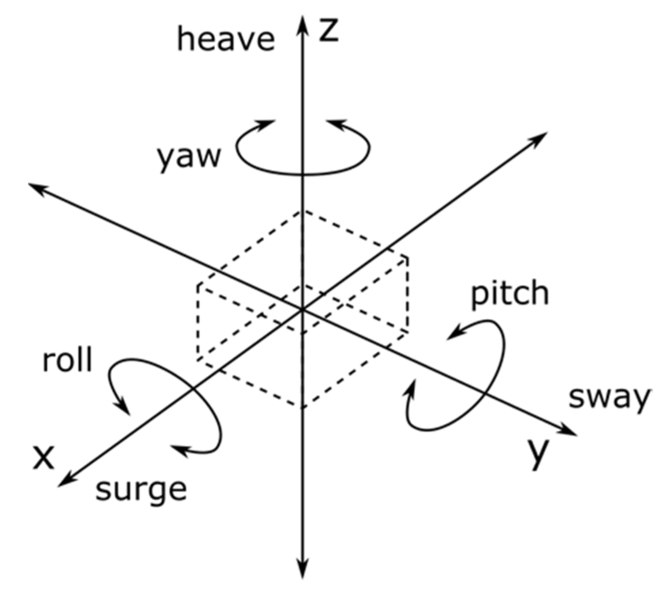
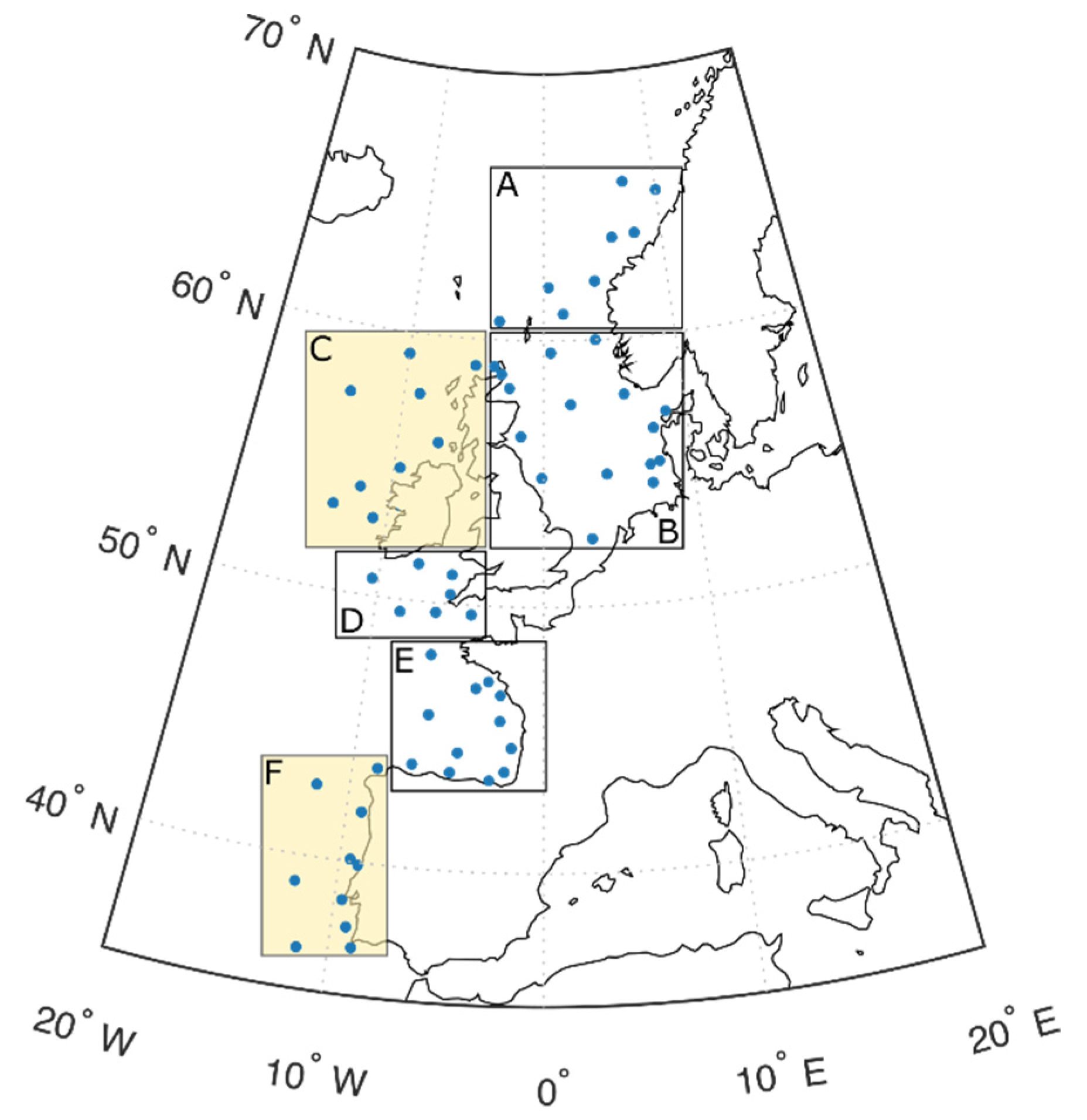


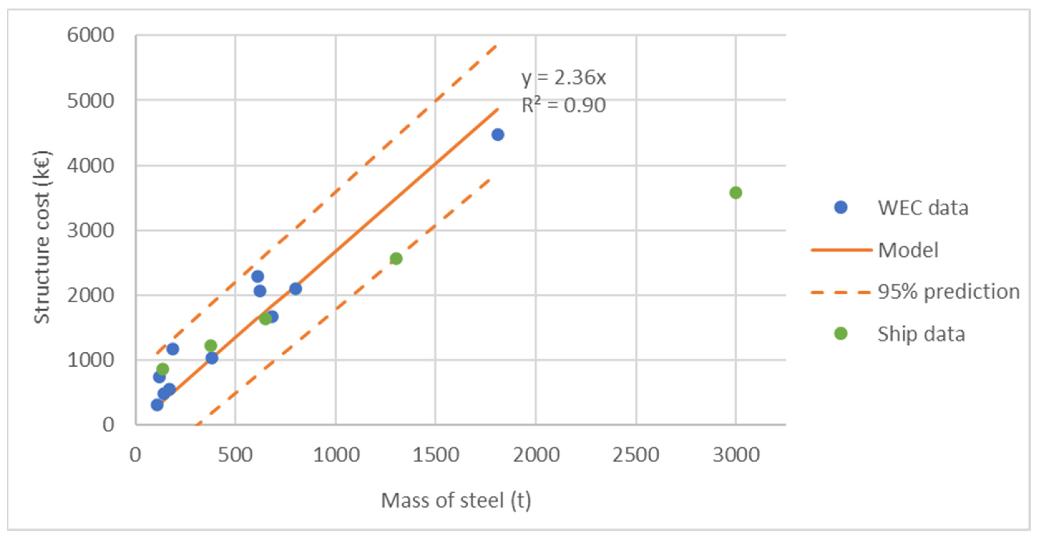
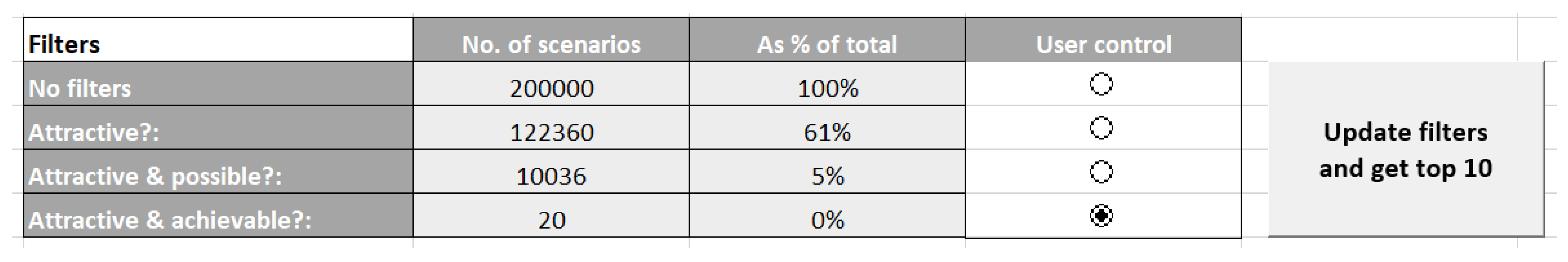
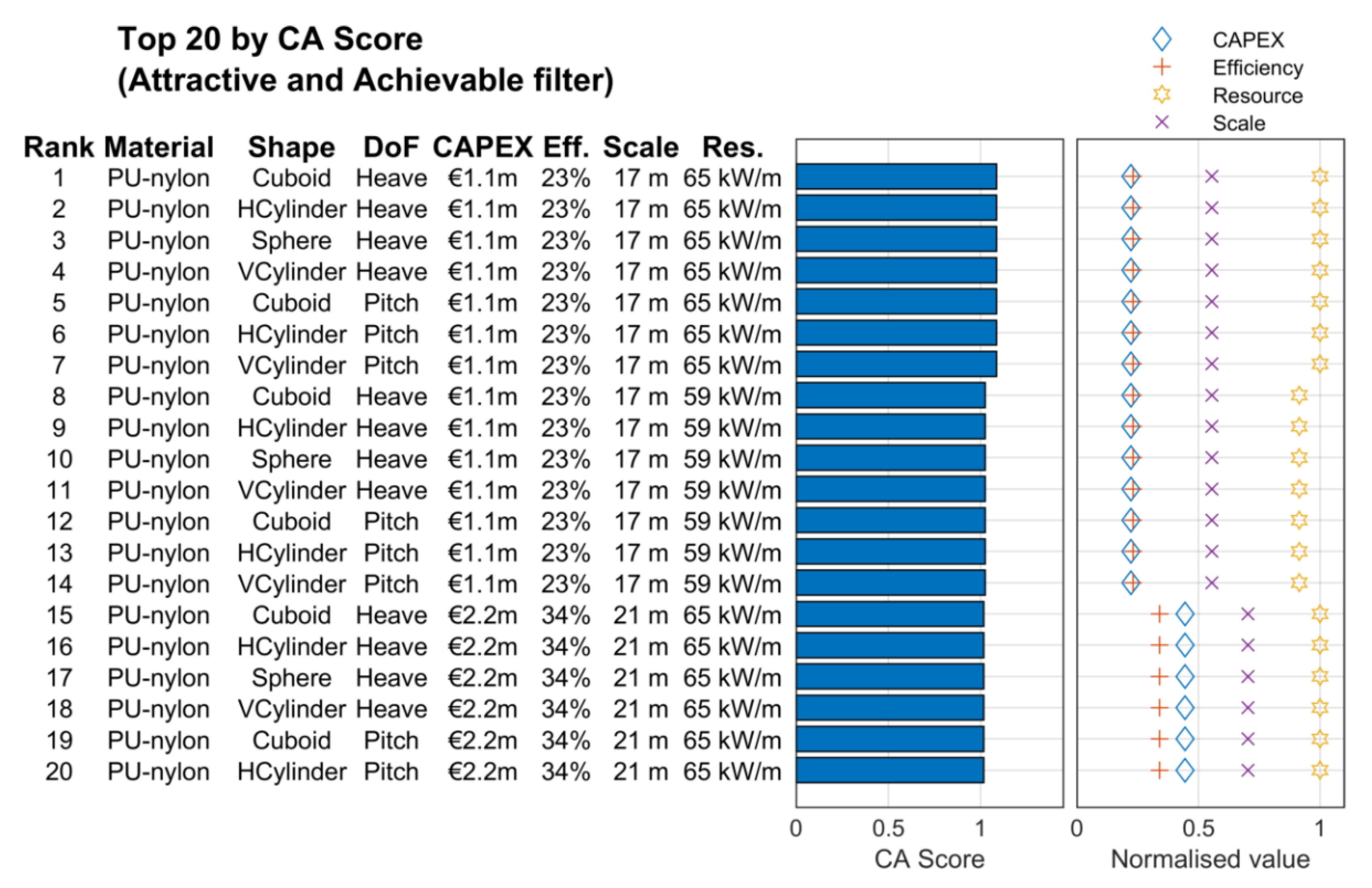


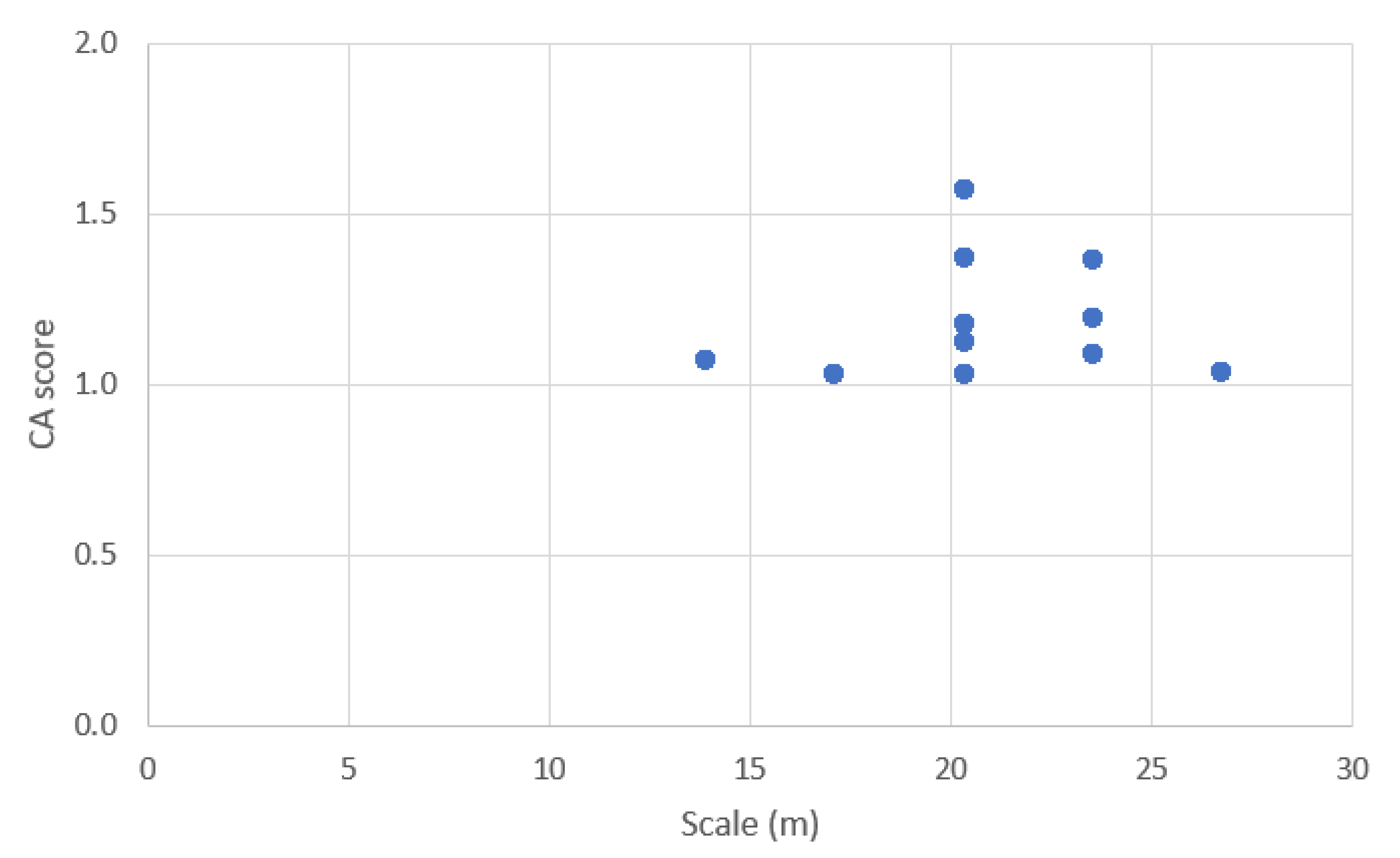
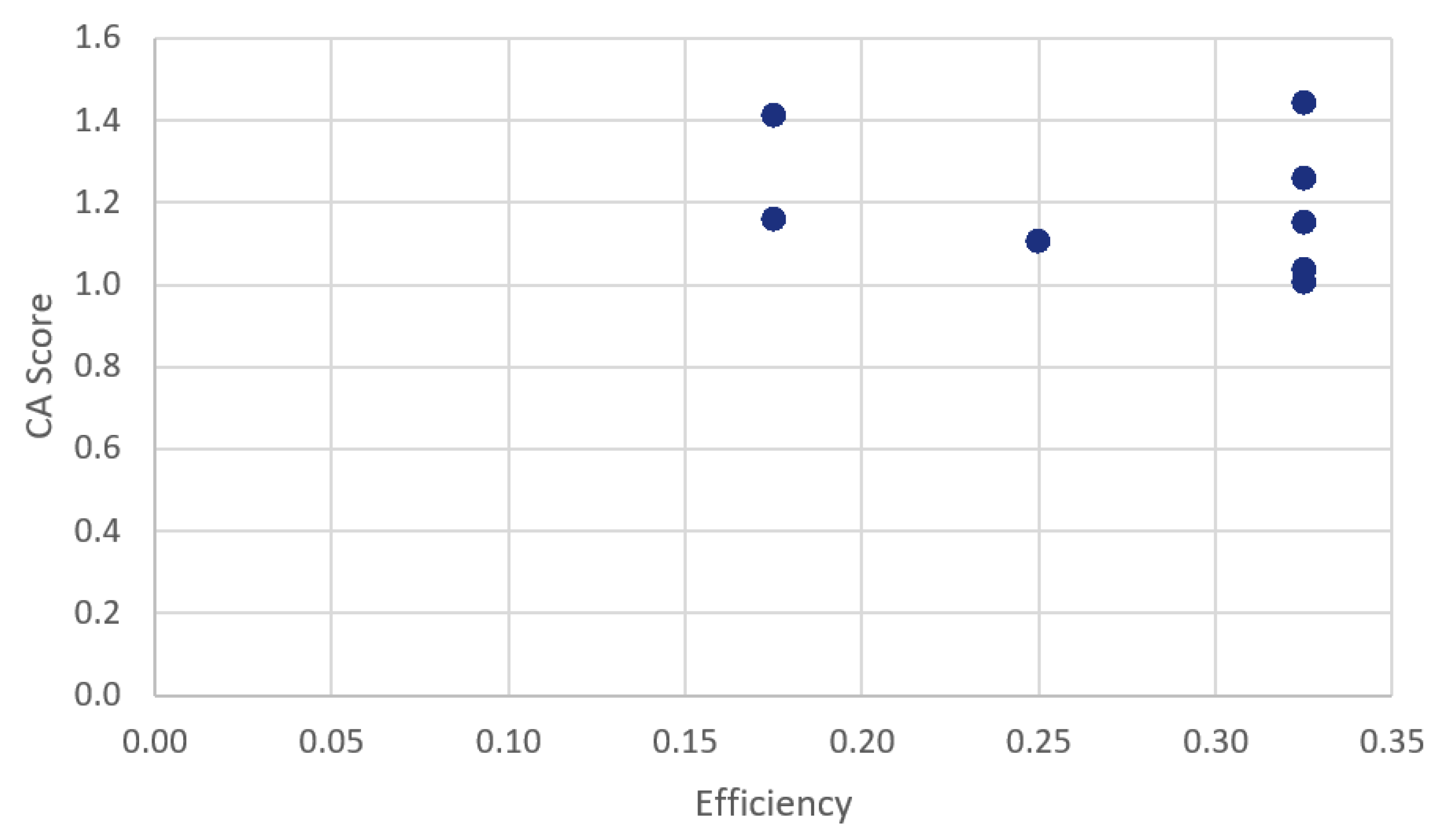

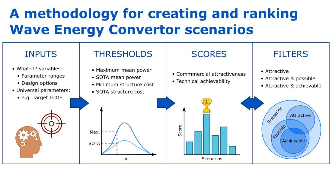
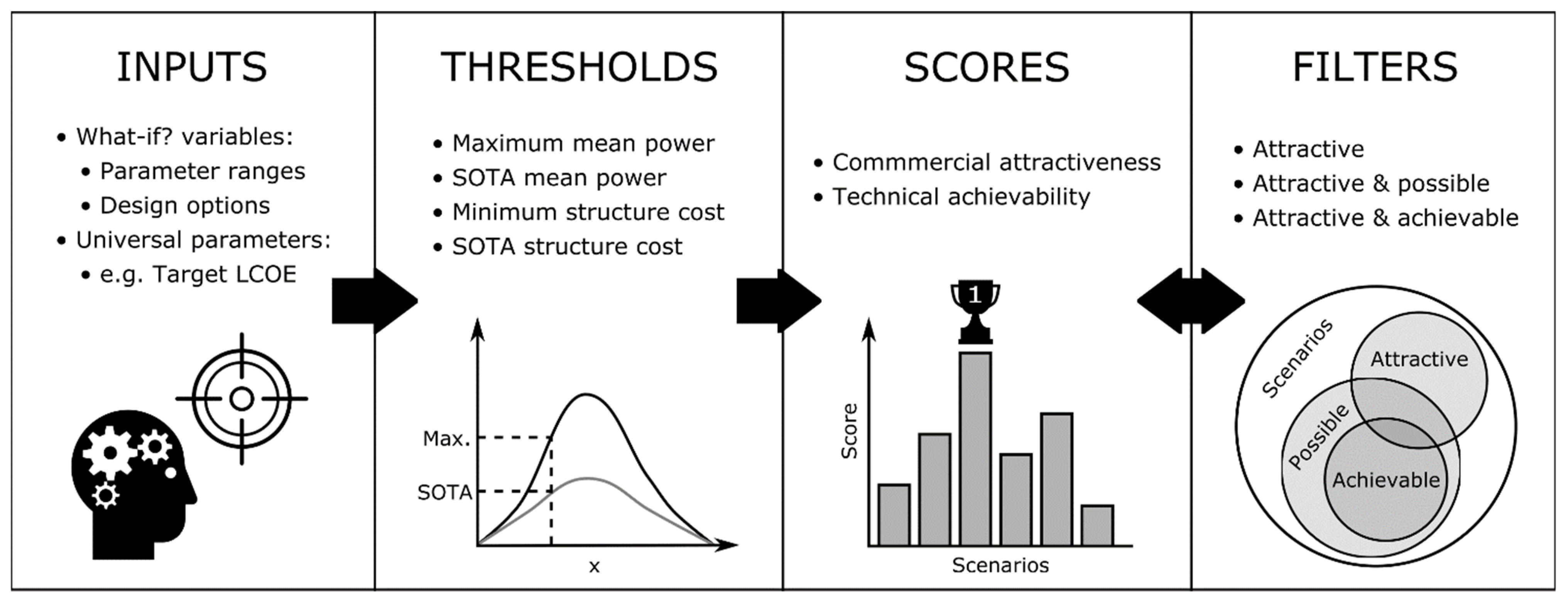
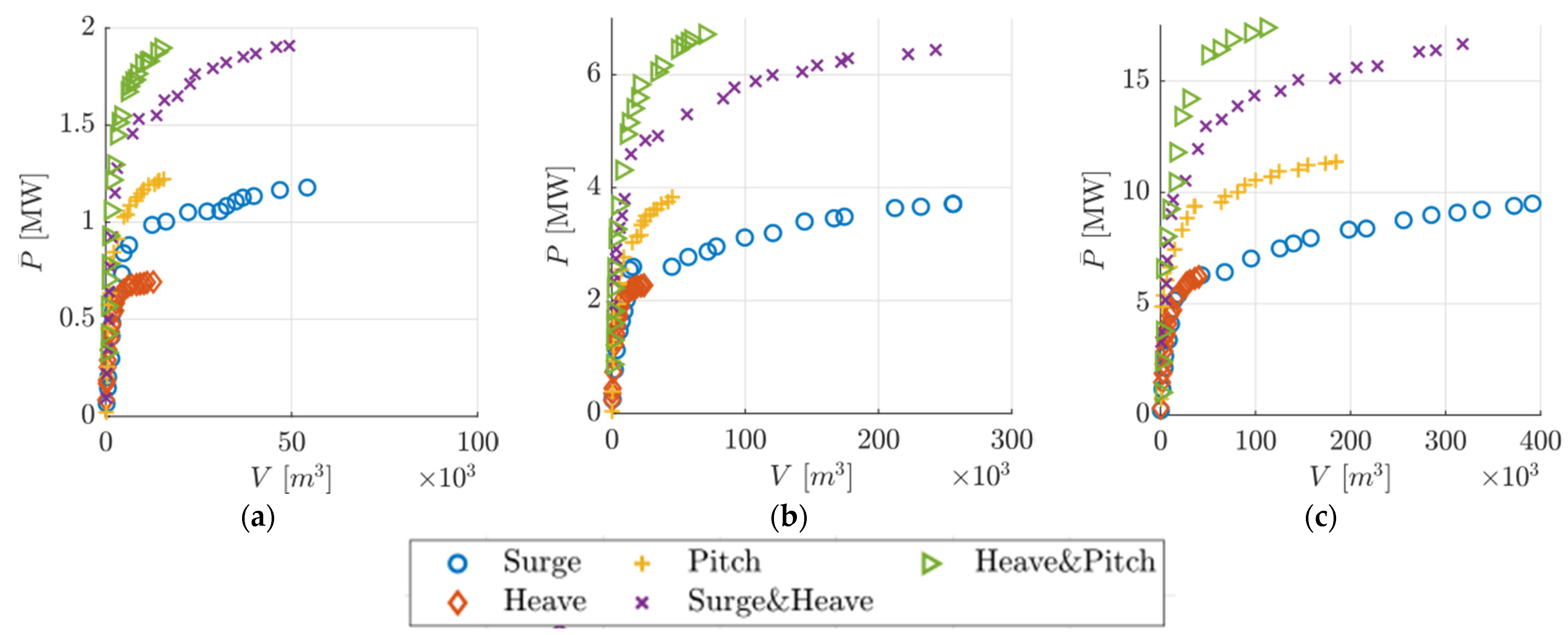
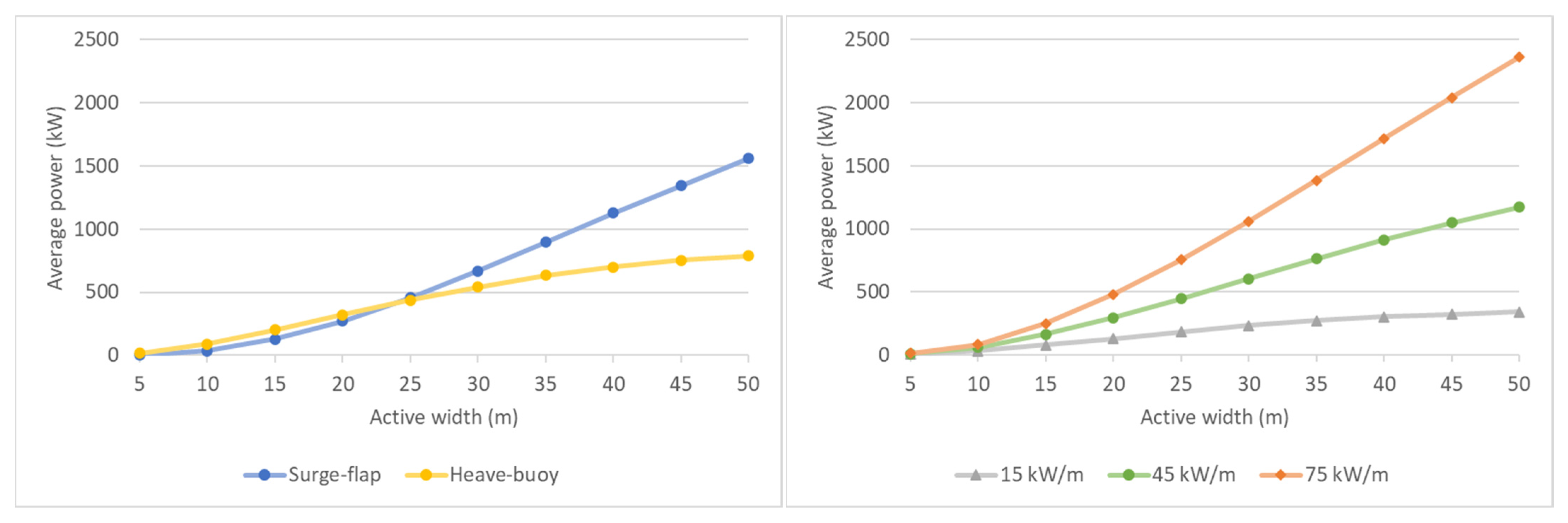
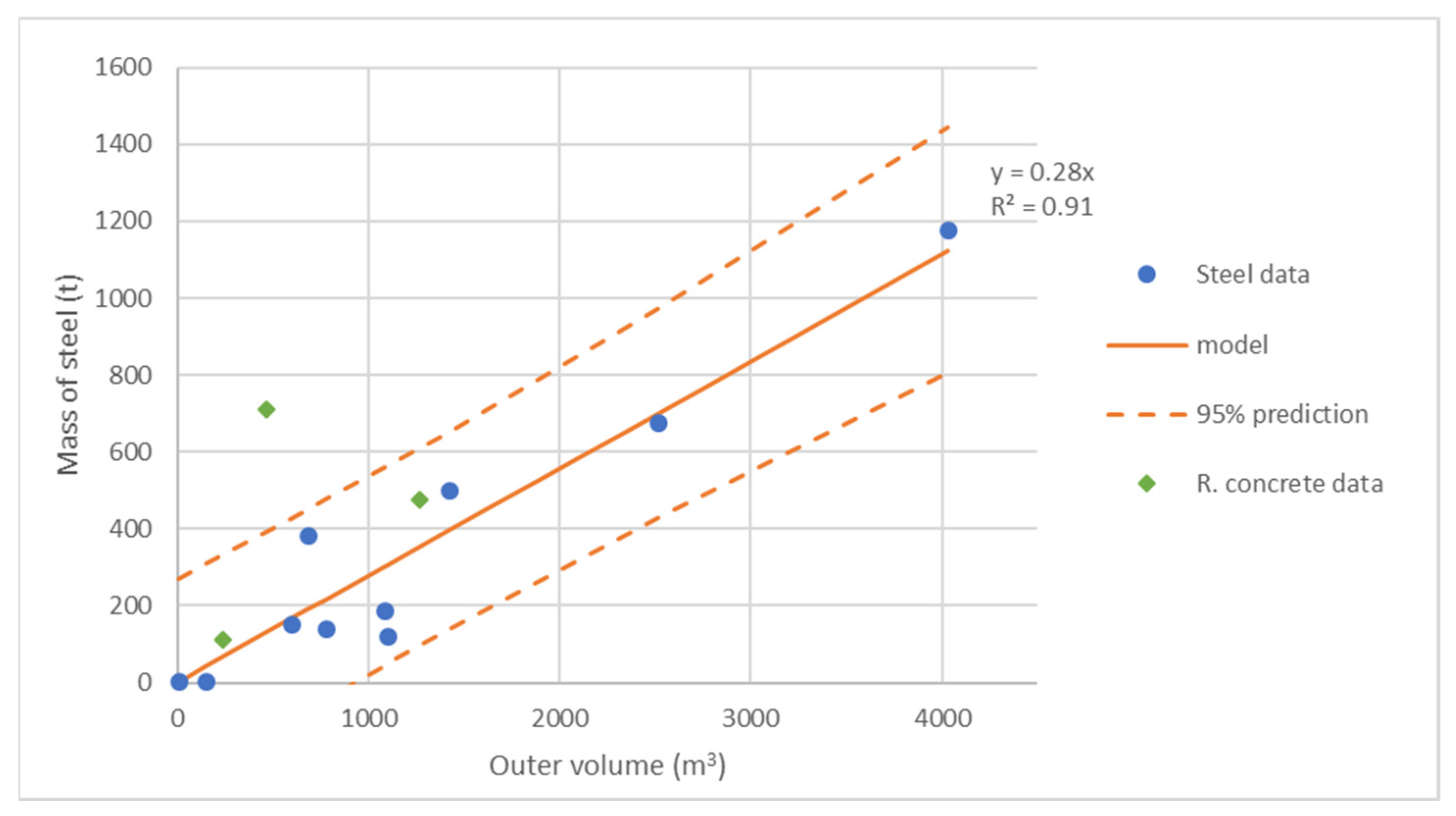
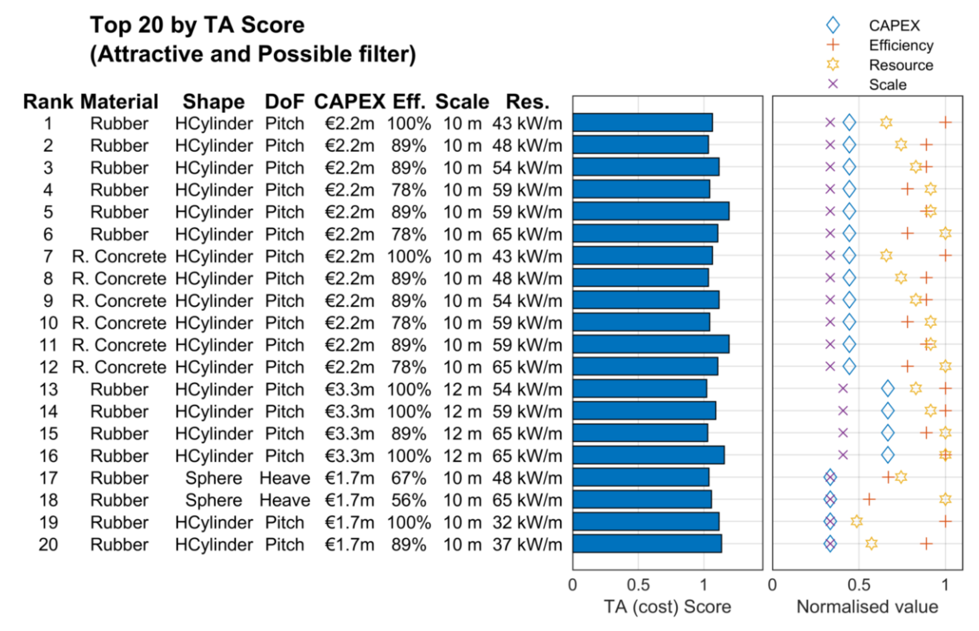
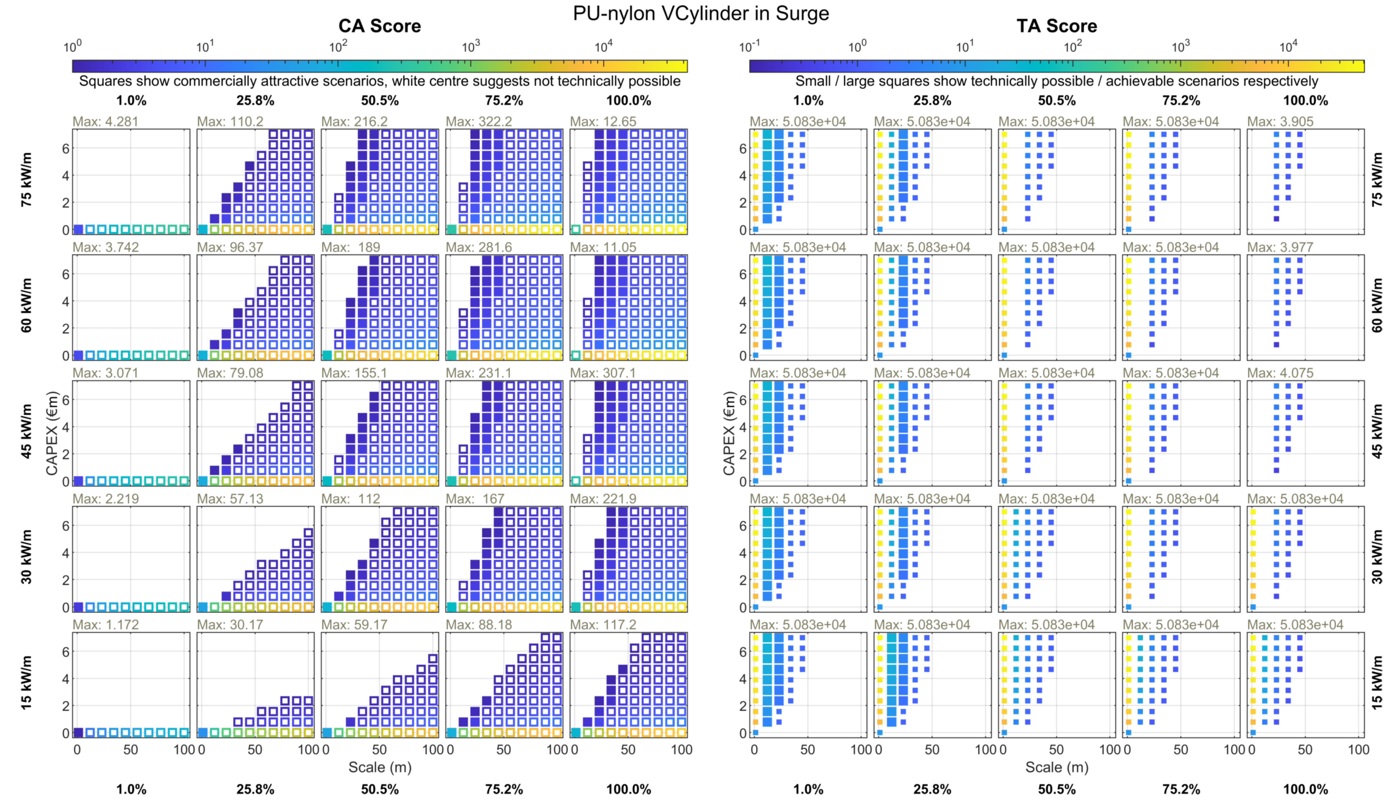