Article

Evolution of Temperature Field around Underground Power Cable for Static and Cyclic Heating

1
Geomechanics & Geotechnics, Kiel University, 24118 Kiel, Germany
2
Mechanical Engineering Department, College of Engineering, King Khalid University, Abha 61411, Saudi Arabia
3
Research Center for Advanced Materials Science (RCAMS), King Khalid University, Abha 61413, Saudi Arabia
4
Civil Engineering Department, College of Engineering, King Khalid University, Abha 61411, Saudi Arabia
*
Author to whom correspondence should be addressed.
Current address: GeoAnalysis Engineering GmbH, 24118 Kiel, Germany.
Energies 2021, 14(23), 8191; https://doi.org/10.3390/en14238191
Submission received: 18 October 2021 / Revised: 13 November 2021 / Accepted: 25 November 2021 / Published: 6 December 2021

Abstract

:
Power transmission covering long-distances has shifted from overhead high voltage cables to underground power cable systems due to numerous failures under severe weather conditions and electromagnetic pollution. The underground power cable systems are limited by the melting point of the insulator around the conductor, which depends on the surrounding soils’ heat transfer capacity or the thermal conductivity. In the past, numerical and theoretical studies have been conducted based on the mechanistic heat and mass transfer model. However, limited experimental evidence has been provided. Therefore, in this study, we performed a series of experiments for static and cyclic thermal loads with a cylindrical heater embedded in the sand. The results suggest thermal charging of the surrounding dry sand and natural convection within the wet sand. A comparison of heat transfer for dry, unsaturated and fully saturated sand is presented with graphs and colour maps which provide valuable information and insight of heat and mass transfer around an underground power cable. Furthermore, the measurements of thermal conductivity against density, moisture and temperature are presented showing positive nonlinear dependence.

1. Introduction

Modern society’s industrial growth and development are closely linked with its mastery of energy generation, transportation, and distribution effectively and efficiently. The past century saw a massive stride in this endeavour and a monumental shift towards energy generation from green sources [1]. The green sources are confined to favourable locations and require an efficient and reliable network to transport the generated power to industrial consumption centres [2]. The conventional power transmission network uses high tension transmission lines, which are prone to high winds, snow and ice storms, earthquakes, electromagnetic pollution, and metal wire theft [3,4,5]. The overhead lines also render a vast area underneath unusable. The limiting factor with the underground power cable system (UPGS) is the melting temperature of cross-linkable polyethene (XLPE) around the conductor which heats up due to resistance to electric current flow (Joule heating) [6,7]. Therefore, in the past decades, intensive research has been conducted to improve the understanding and enhance the knowledge about heat and mass movement around the UGPS. Simultaneously, research has been conducted to improve the trench backfill material [8,9,10,11]. However, the use of such costly materials for a vast stretch renders it impractical economically.
Although the problem of heat and moisture movement around UGPS seems straightforward, it is an interplay among the surrounding hydro-thermal interactions due to changes in surrounding environmental and biological conditions (Figure 1). The hydrological conditions are the estimation of surface runoff and infiltration after a precipitation event. The problem becomes more complex in regions with snowfall, which results in partial freezing of the ground and sudden outflow with snowmelt causing rapid changes in surrounding temperature and moisture fields [12]. The computation of thermal losses in the surrounding soil, a three-phase partially saturated porous media, is complex. Heat is transported by sensible, convective and latent modes driven by a gradient in temperature, liquid water and water vapour, respectively, [13,14,15,16]. The heat transport by these mechanisms is hard to measure in the laboratory under controlled laboratory conditions [17,18,19] but becomes impracticable in field conditions with variation in humidity, precipitation, fluctuating water tables, and variable wind velocity along with moisture and temperature-dependent material parameters such as the effective thermal conductivity, heat capacity, vapour diffusivity, density, moisture storage capacity and unsaturated hydraulic conductivity [20]. The environmental factors range from measurement of air and ground temperatures, evaporation, humidity, soil moisture content, and wind velocity. These parameters directly contribute to convective heat transfer and moisture transfer coefficients controlling free surface heat and moisture losses [21]. Finally, the biological factor involves calculating evapotranspiration from different plants, and knowledge of the flora and fauna that grow and dwell in the vicinity of the UGPS is desirable [22].
The simplified theoretical work is presented by Neher and McGrath [23] for calculation of thermal fields around a UGPS considering the series conduction heat transfer model which is later improved [24] and is adopted by the IEC [6]. The method computes quickly with reasonable accuracy for low-power transmission cables where conduction heat transfer dominates, and the moisture field around the cable is relatively constant. However, as the amount of current in the cable increases, so does the generated heat, and thus simplified calculations start to underestimate the temperature field [25]. Furthermore, the recent development in high voltage direct current cables (HVDC) and the transcontinental underground cable technology (elpipes) [26], which can transfer up to 20 GW and will produce a substantial amount of heat and drying around the UGPS, requires fundamental development and a deeper understanding of the complex interplay of the involved physics, phenomenon and boundary conditions.
In the past few decades, many researchers have tried to approach the coupled heat and mass transfer problem from theoretical, numerical and experimental sides. Jury [27] solved the full coupled thermodynamic equation with simple boundary conditions and straightforward assumptions, resulting in a decoupling of heat and mass transfer processes. He showed a good agreement with the mechanistic equations developed by Philips and deVries [13]. However, the theoretical work of mechanistic coupling of heat and mass transfer processes with many rudimentary assumptions and simplifications, such as soil is homogeneous and isotropic in a macroscopic sense, each phase is in thermodynamic equilibrium, and free convection in the gas phase is absent, applies to limited scenarios.
Numerical modelling due to abilities such as considering actual boundary conditions and complex material, geometrical nonlinearity and physics coupling [28] is applied to solve the coupled heat and mass transfer equations in sequential [29] and fully [25] coupled fashion. The dominant method used is the finite element method (FEM) [30] due to its superior ability to model nonlinearity (geometrical and material), better convergence, ability to deal with complex boundary conditions, and the solution in both weak and strong forms [31]. However, the FEM showed promising results but is limited to deal with a sudden change in moisture content due to drying or outflow, implementation of temperature and moisture dependent material parameters and considerable computation time. Marshall et al. [29] showed the effect of rainfall on the temperature field by coupling the heat transfer and unsaturated laminar flow equations. In a more extensive work, Kroener et al. [25] solved the full coupled Phillips and deVries [13] equation with FEM and real boundary conditions including precipitation, wind speed, solar flux and annual temperature variation and showed that the IEC [6] method underestimates the temperature field by a significant margin. In another work following the Finite Difference Method (FDM), the effect of daily ambient conditions on the UGPS is studied [32]. All the numerical methods presented were applied for sand type soil and the range in which vapour transfer by diffusion dominates (micropore size 10 6 m). The model is also limited to micro-scale fluid flow in the pores by diffusion and holds good for sand and larger granular system with bigger pores, but fails to consider nanoscale flow in slit-clay and clay type soil [14]. The movement of fluid in-between micro and nano-size pores is a combination of diffusion and effusion. A few experimental studies have been conducted so far to model diffusion–effusion driven drying in cemented particulate matter [33]. The lack of knowledge is due to improper understanding of the couple effects, and also the unavailability of the coupled partial differential equations to define the problem considering diffusion-effusion coupled with the heat transfer in unsaturated porous media is a limitation in proper modelling with numerical methods [34].
The experimental programs to study the distributions of temperature and moisture fields around the UGPS have been conducted at both field and laboratory scales [35]. The field-scale experiments offer a rich dataset of the real-world boundary and environmental conditions but are challenging to set up and resource-intensive [36]. The substantial effort is the work by Adams et al. [37] where the field measurements have been reported the first time. In recent work, the field measurements are also presented by Trinks [38] for different soil and surrounding conditions for 110 kV cables. Ainhirn [39] presented the field measurements of UGPS, and a sensitivity analysis is conducted for various environmental and material parameters. The study showed that surrounding soil temperature and thermal conductivity have the highest influence on the cable temperature and control the ampacity.
The field-scale experiments lack fine control on the boundary conditions and material heterogeneity, which is omnipresent influencing the measured temperature and moisture fields [40]. The small number of datasets available from field-scale experiments with many variables render the results limited in scope. Therefore, small- and large-scale laboratory tests gained more importance where process-controlling parameters are regulated in a better fashion for an adequate understanding of the physical phenomenon [41,42]. The small-scale laboratory setup to measure the temperature and moisture fields with a simple cylindrical cell is conducted with the top and bottom of the cell acting as a heat source and sink, respectively. The moisture and temperature sensors are placed in the longitudinal middle plane. The setup is used to study the behaviour of sand for theoretical and numerical models and is applied to quantify the response of modified backfill material as well [43]. The setup is limited in nature and representation, as it does not represent a radial symmetric UGPS embedded in the ground. For a better demonstration of UGPS in-ground, a medium size rectangular box with a heated cylinder is installed, and the temperature and moisture measurements are performed for sand [17], modified backfill [44] and heterogeneous layered media [40]. The experiments offer a good insight into the development of temperature and moisture fields with changing heating and boundary conditions. However, the effect of the boundary conditions and accumulation of generated heat in the surrounding soil mass due to limited size, resulted in a higher temperature field near the heater and excess moisture near the boundaries due to diffusion moisture transfer [36]. Therefore, large-scale boxes fitted with single [2] and multiple heaters [45] are built to eliminate the boundary effect, and have sufficient heat dissipation characteristics. The multiple heater setup offers a better understanding of the interacting temperature and moisture fields around the UGPS. However, the multiple horizontal or vertical arrangement is preferred for low voltage cables below 230 kV and is used for power distribution, or short-distance power transmission [36,38]. For long-distance high voltage transmission above 345 kV, the cables are placed at a maximum possible distance apart to avoid much interaction in moisture, temperature, electric and magnetic fields. The non-interacting cables help in ease of construction and maintenance as well. Therefore, for high voltage UGPS, the behaviour is often correlated to a single embedded heater in the soil.
The diurnal and seasonal fluctuations in power demand and variable production from green energy plants create a cyclic thermal loading of the cable. The cyclic thermal loading of the cables is studied in both numerical [46] and theoretical [47] fashion. However, no experimental study is reported in the literature. The changing weather conditions produce varying moisture in the surrounding soil, combined with cable heating it can result in a dry-out zone around the cable. However, the previous studies have only reported the two extreme conditions, namely, the dry and fully saturated cases. The soil around the cable under atmospheric boundary condition is unsaturated and tries to attain dynamic equilibrium.
Therefore, in this study, we performed a series of experiments with dry sand and an embedded cylindrical heater, heated to a temperature of 70 and 90 ℃ with cyclic heating to capture the diurnal fluctuations. Furthermore, the effect of moisture on the temperature field around the power cable is studied with, a series of five days of static heating temperature test of 70 ℃ with dry, unsaturated and saturated sand. The measurement of thermal conductivity for different density, moisture and temperature is also performed to provide material parameters for theoretical and numerical modelling. The test results could be used to benchmark such models.

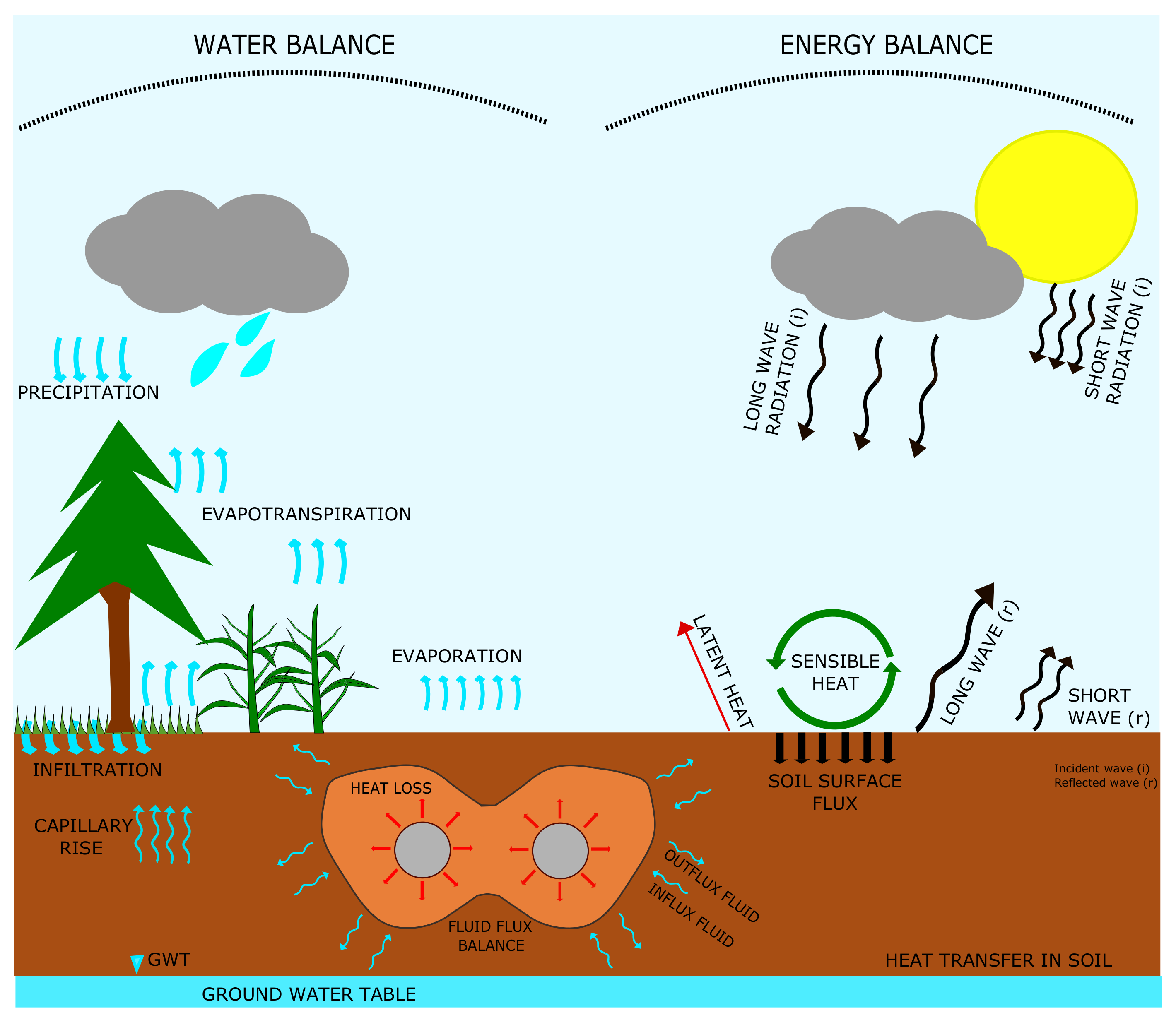
2. Theory of Coupled Heat and Mass Transport in Sand

Heat and mass transfer in soil are complex interactions among gas, heat, liquid water and vapour flow. A detailed study of heat and mass transfer in sand based on the thermodynamics of the irreversible process is presented [27]. The agreement between theory and experiment was only partial and required many assumptions. The other approach is the ‘mechanistic’ explanation of the process and is used for many porous media due to simplicity of computation of diffusion parameters [13]. The theory has limitations, such as the hysteresis relation between the moisture potential and the moisture content is not taken into account. Furthermore, deformation of the solid matrix is not allowed, and the porous medium must be homogeneous and isotropic in a macroscopic sense. The phase change phenomena of boiling and freezing, and thawing are not included. The Knudsen effect in the gas phase and the surface phenomena at the interface between the matrix and the liquid are not considered. The following simplifications are also applied for the formulation of the governing coupled partial differential equations. For fluids in the porous media, the solutes are assumed to be absent; thus, the liquid phase is pure water, and the movement is driven by viscous flow under the influence of capillary and adsorptive forces.
Similarly, the vapour movement is by diffusion in the gas-filled pores and air as an inert gas, and the free convection in the gas phase is neglected. In the case of heat transfer, the radiation effect is negligible, and the assumption of local thermodynamic equilibrium among the liquid in contact with its vapour holds. Furthermore, the total pressure is assumed uniform and constant, and the temperature dependence of physical constants is neglected [14]. With these limitations and assumptions, the mass balance in the porous media is given as:
q w = K ( ψ + g z )
q v = q v , i + q v , T = D v c v h D v h s T
q h = λ T + ( L + T C w ) q v + T C w q w
ρ w θ t = . ( q w + q v )
[ C m ρ m x m + C w ρ w θ ] T t = . q h
ρ w t θ ( ψ ) = . K ( ψ ) ( ψ + g z ) + D v h c v M w R T ψ + D v h s T
( C m ρ m x m + C w ρ w θ ( ψ ) ) T t = . λ T + ( T C w K ( ψ ) ( ψ + g z ) + ( L + T C w ) D v h c v M w R T ψ + ( L + T C w ) D v h s T )
The above two equations are solved with the finite element [25] and finite difference [32] methods with atmospheric boundary conditions for the UGPS to compute temperature and moisture fields. However, the “mechanistic” formulated equations offer significant errors at low and high moisture values and rapidly changing saturation levels. Therefore, for an accurate estimation of the temperature field around the heater for such a complex problem, experimental studies are ideal and are conducted here.

3. Materials and Methods
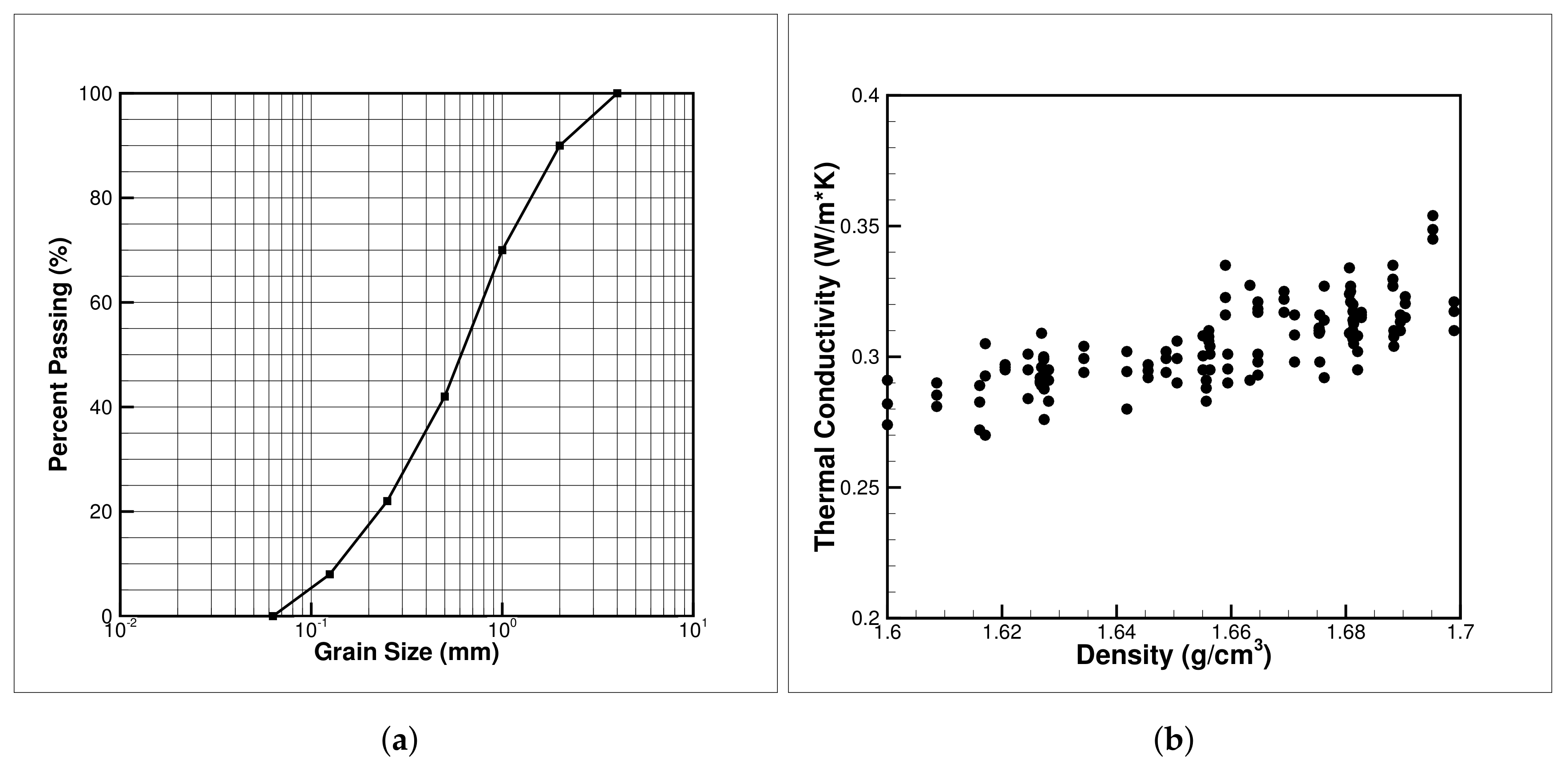
The heat and mass transfer around the power cable is studied with sand around a heated cylinder. The clay-type soils are avoided around UGPS due to low thermal conductivity, high heat capacity and susceptibility to crack at low moisture. The sand is procured from a pit near Flintbek, Germany, and material characterisation is performed.

3.1. Sand

The geotechnical laboratory investigation shows the sand to be a uniform sand with particle size ranging between (0–4) mm. The X-ray Diffraction (XRD) of the sand is plotted in Figure 2 and shows that the sand is made up of more than 98% Quartz mineral. Furthermore, Table 1 provides the XRF measurement performed on the sand and confirms the XRD measurement. The main constituent is the silica mineral and the rest of metal-oxides in trace amounts.

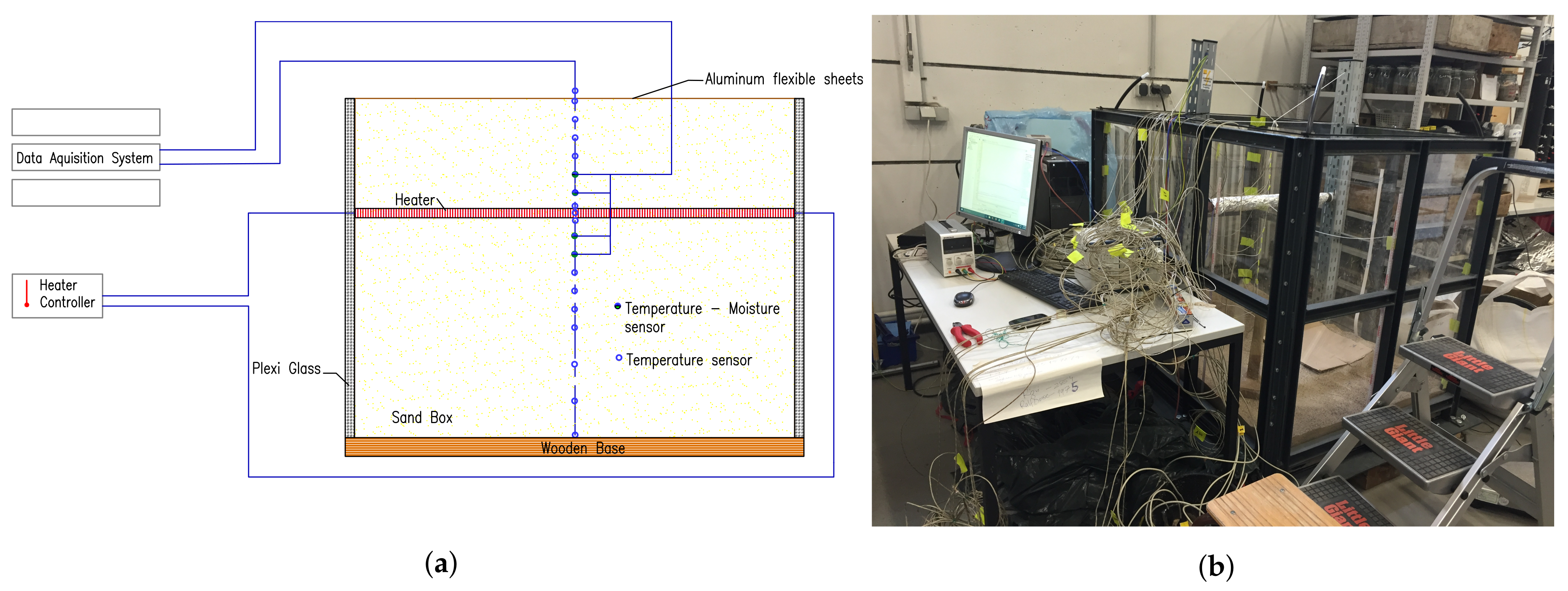
3.2. Experimental Setup

A large scale test apparatus is designed and operated to simulate a trench for the underground power cable. The test apparatus has a unique heavy-duty iron frame which was fabricated to hold the contents of the large sandbox. The large-scale sandbox (test apparatus) is rectangular in shape, having 1800 mm as the longest side and is 1200 mm high and 1000 mm wide (see Figure 3). It is installed with Plexiglas for clear visual observations of the contents in the box, which could be operated at temperatures ranging −30 to 180 ℃. Plexiglas is used instead of normal glass panels as these are more resistant to thermal shocks. Plexiglas panels are curbed at the edges, and rubber lining is installed to prevent cuts to the working personnel and ensure water-tight conditions inside the box at the same time. The top of the sandbox is covered with flexible aluminium sheets to avoid any heat escape.
Since our test apparatus is designed for carrying out tests for both saturated and unsaturated moisture conditions, four flexible rubber pipes are installed at each corner for the water supply running till the bottom of the box. The sandbox is also installed with a drainage outlet. Sand inside the box is filled in a layered manner, with each layer being 100 mm high and tamped with a wooden bar. The large-scale sandbox is isolated from the floor using rubber sheets and solid wooden planks. It helped reduce the heat loss and avoid the transfer of heat to or from the sandbox. A laminated paper scale is also stuck at one of the edges of the sandbox for measuring purposes. Commercially available water sealants are also used to ensure extra safety against moisture loss from the box.
A tubular heating rod is installed inside the sandbox to replicate as an underground power cable (see Figure 3a). The heating rod is 800 mm long and 50 mm in diameter, placed firmly between the two vertical stands. The vertical stands are each 50 mm wide amidst which the heater is placed parallel to the shortest edge of the box, i.e., along the 1000 mm long side. The tubular heater rod is positioned at a distance of 750 mm from the bottom of the box. The arrangement and schematics of the heater rod are shown in Figure 3b.
The oven-dried sand is placed in the box in a layer-wise fashion of 10 cm each. The grain size distribution is plotted in Figure 4a. The full saturation is achieved with a bottom-to-top approach to saturate the sand inside the box, removing any trapped air amidst the sand grains (inter-granular pores). The unsaturated condition is created by fully saturating the sand and then draining to a water table of 45 cm. A waiting time of 24 h is allowed before the test to achieve uniform moisture distribution.

3.3. Thermocouples and Heater

National Instrument’s K type Thermocouples (TC’s) and three-pin 150 mm long Time Domain Reflectometers (TDRs) were used for measuring temperature and moisture, respectively. In total, thirty-two TC’s and eight TDR’s were installed at selected locations. The TC’s have an operating range of −55 ℃ to 550 ℃ with an accuracy of ±0.5 K as reported by the National Instruments. Furthermore, the sensors presented a deviation smaller than ±0.3 K when tested against the resistance temperature detectors (RTDs) Pt-100 sensors. The heater temperature is also measured using four TC’s placed circumferential on top, bottom, and opposite sides. The average of the four TC’s is used as the temperature of the heater for comparison purposes.
Each sensor is cross-checked before finally putting them to work by testing on a water-filled box fitted with 4 Pt 100 sensors, which showed results in a range of 0.25 K, i.e., within permissible error limit. Furthermore, to measure the ambient temperature, two TC’s are placed outside the testing apparatus.

4. Discussion on Effective Thermal Conductivity of Sand

The effective thermal conductivity (ETC) of soil depends on the degree of saturation, density, temperature, mineralogical composition, particle size, shape, gradation, inter-particle physical contact, properties of soil components, ions, salts, additives, hysteresis effect, etc. [48]. However, the dominant factors controlling the changes are the environmental factors, such as the degree of saturation, porosity and temperature. The effect of ETC on the degree of saturation and porosity is well studied in the literature, and it is shown that degree of saturation is more sensitive than the porosity [49]. The effect of temperature on ETC is studied recently and showed a positive correlation but of a nonlinear trend [50,51]. The ETC of the sand used in the experiment is tested with varying degrees of saturation, density and temperature.
Figure 4b shows the variation of thermal conductivity with density. The standard KD2 pro device with a TR1 needle is used to measure the thermal conductivity. A minimum of three observations are made, and the mean value is plotted here. A total of 81 measurements were performed on the oven-dried sand. A linear correlation is found between the parameters and agrees with the previously presented results in the literature.
Figure 5a shows the effect of temperature on the thermal conductivity of the soil. The saturation is controlled by mixing a specified amount of water with the oven-dried sand. The samples are placed in a climate chamber with a membrane to avoid moisture loss. The samples are allowed to equilibrate for 4–6 h before performing the measurements. Three temperatures of 20, 50 and 70 ℃ are taken. The saturation is also checked pre- and post-measurement with the oven drying method, and it is found to defer less than 1% for all the samples. The measurements show a clear positive correlation with temperature, and the maximum value is achieved at 70 ℃. However, it is also observed that the difference diminishes at higher saturation values (Figure 5a). The temperature above 50 ℃ vapour flux starts to play a critical role in heat transfer through convection. The effect is visible with a high thermal conductivity value at lower saturation. However, for higher saturation, the vapour permeability decreases, so the vapour movement ceases to exist, thus bringing the mode of heat transfer to conduction only, showing a lower thermal conductivity value. The convective heat transfer becomes more significant at even higher temperatures, thus should be included in energy geotechnics calculation above 50 ℃.
Figure 5b shows the effect of density on the effective thermal conductivity of sand. A positive correlation is observed here as well. The sand in the study is poorly sorted and thus allows higher compaction. A higher compact results in more inter-granular contact and facilitates conduction, the dominant mode of heat transfer in the sand at room temperature. Poorly sorted sand has a better ability to resist drying due to lower permeability and porosity, which hinders movement of vapour from the heat source into the surroundings. Thus, well-sorted sand is avoided, which shows thermal instability with rising temperature and dries out quickly.

5. Results and Discussion

The underground power cables in previous studies are modelled with a heated cylinder with defined heat flux, or temperature [17,45]. However, temperature-controlled tests offer better control and are closely related to insulation melting condition. The rudimentary assumption of cable carrying a constant electric current allows equilibrating with the surrounding soil. Therefore, most of the experimental results reported in the literature are conducted using static thermal loading. However, the peak and nominal demands change daily, and with the integration of non-conventional energy generations from sources such as wind, tidal and solar, the fluctuation has increased many-fold. The diurnal and seasonal fluctuations result in cyclic thermal loading of the cables. Therefore, static and cyclic thermal loading tests are performed with heater temperature of 70 and 90 ℃ associated with nominal and maximum cable operating temperatures. Four thermocouples are placed at 90 on the outer circumference of the heater and an aluminium foil is wrapped to give uniform heat distribution from the cable. The average value of the four sensors is plotted as heater temperature in both static and cyclic thermal loading scenarios.

5.1. Static and Cyclic Thermal Experiment with Dry Sand

The dry condition is the worst-case scenario for the cable as it results in minimum thermal conductivity and causes a hot spot formation around the power cable. For most of the cable current carrying capacity calculations, a thermal conductivity value of 0.9–1.1 Wm 1 K 1 is assumed. The values are conservative in sandy soil with 5–10% saturation. It is also found that when a critical temperature difference between the dry and the wet regions is exceeded, the transport in the liquid and the vapour phases are in the same direction, resulting in the rapid advance of the drying front [14]. The situation could quickly form around the power cables as the cable surface temperature reaches about 60–75 C [25]. Therefore, the behaviour of the surrounding soil is studied with static and cyclic thermal loading and the results are given in the following sections.

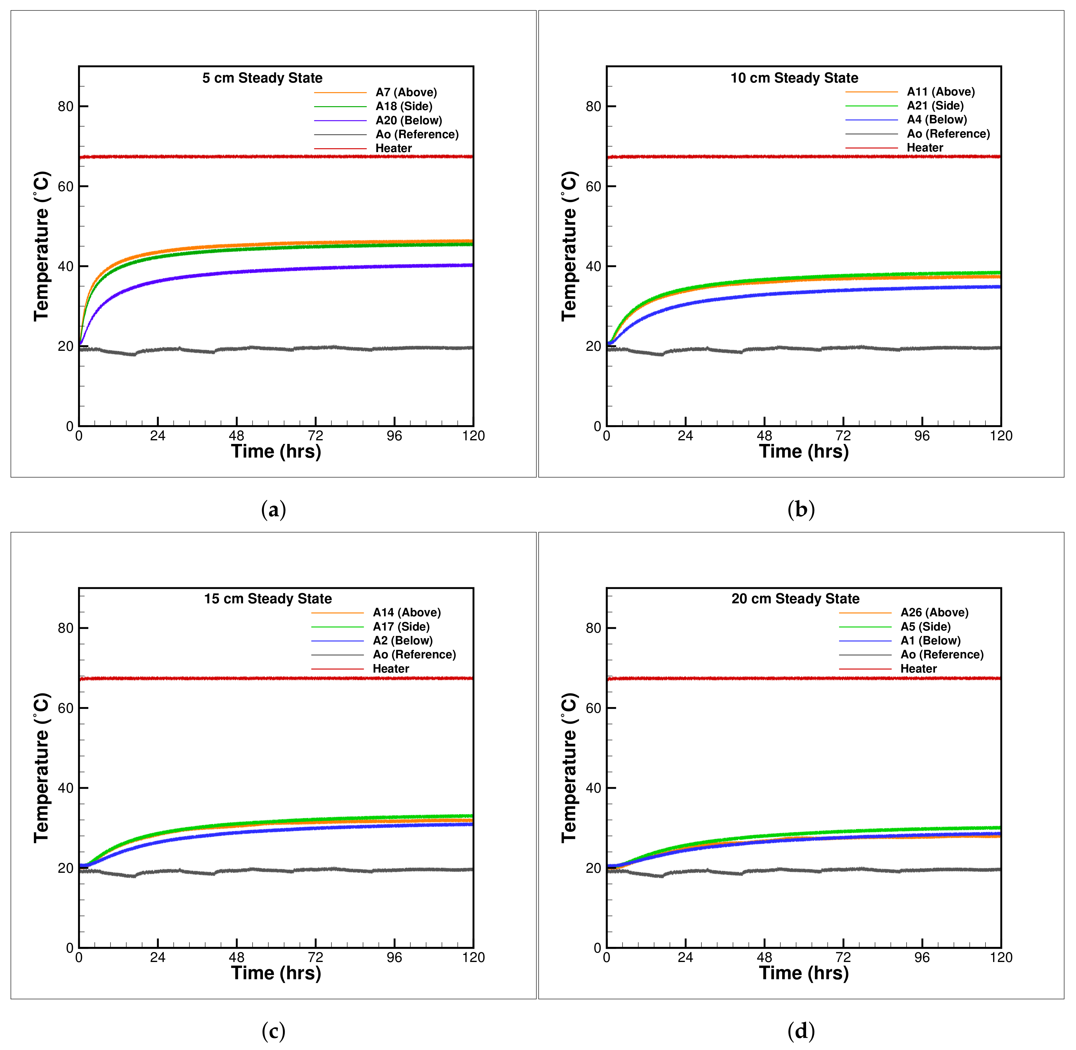
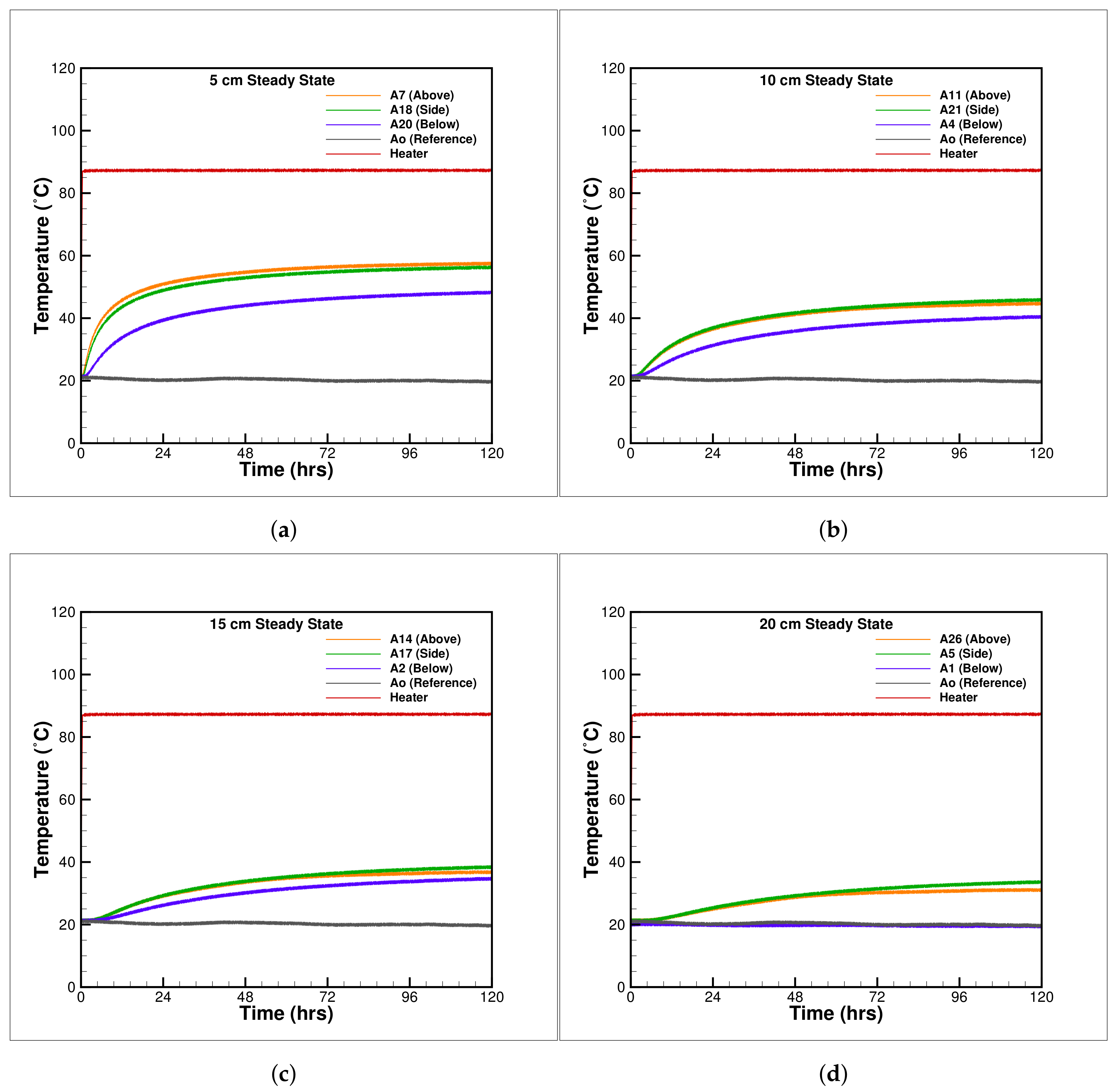
5.1.1. Static Thermal Loading

The long-term behaviour of surrounding soil could be studied experimentally with a heater at either static heat flux or constant temperature. The constant temperature experiments correlates easily to maximum allowed temperature to prevent the XLPE insulation around the cable. Therefore, constant temperature tests are selected and are performed with two different heater temperature of 70 ℃ and 90 ℃.
Figure 6a–d show the temperature measurements around the embedded heater from 5 to 20 cm with thermocouples placed at 90 degrees apart on a semicircular profile. The thermocouple locations are named as top, side and bottom and are used in the text for all other measurements. Figure 6a shows the temperature rise around the heater for all the thermocouples, top, side and bottom along with heater temperature and the surrounding temperature of air outside of the box. The top thermocouple record a higher temperature and the bottom thermocouple records lower temperatures due to the unsymmetrical placement of the heater 45 cm from the top and 75 cm from the bottom surface. The positioning of the heater in such a fashion resembles the placement of underground power cables which are generally buried at a shallow depth ranging between 70 and 150 cm. The smaller thickness of soil above the heater allow large heat movement in upward direction as is offers larger thermal gradient. A significant temperature difference is observed for the top and bottom thermocouples at 5 cm for the thermocouples at 5 cm, but the effect pacifies for thermocouples at 15 and 20 cm. The results show channelisation of heat in vertical direction. Figure 7a–d show the behaviour of the sand with heater temperature at 90 ℃. The bottom thermocouples at all locations recorded the lowest temperatures, and an equilibrium is achieved after 48 h of heating. No significant changes are recorded after it for all the thermocouple.
The highest encountered temperature around the power cables recorded in the summer months when the air temperature is higher than the ground, and heating of the ground results in higher temperatures above the cable and is considered the worst case for the cable insulation melt. A uniform heat dissipation could be achieved with deeper burial but will burden the construction economics.

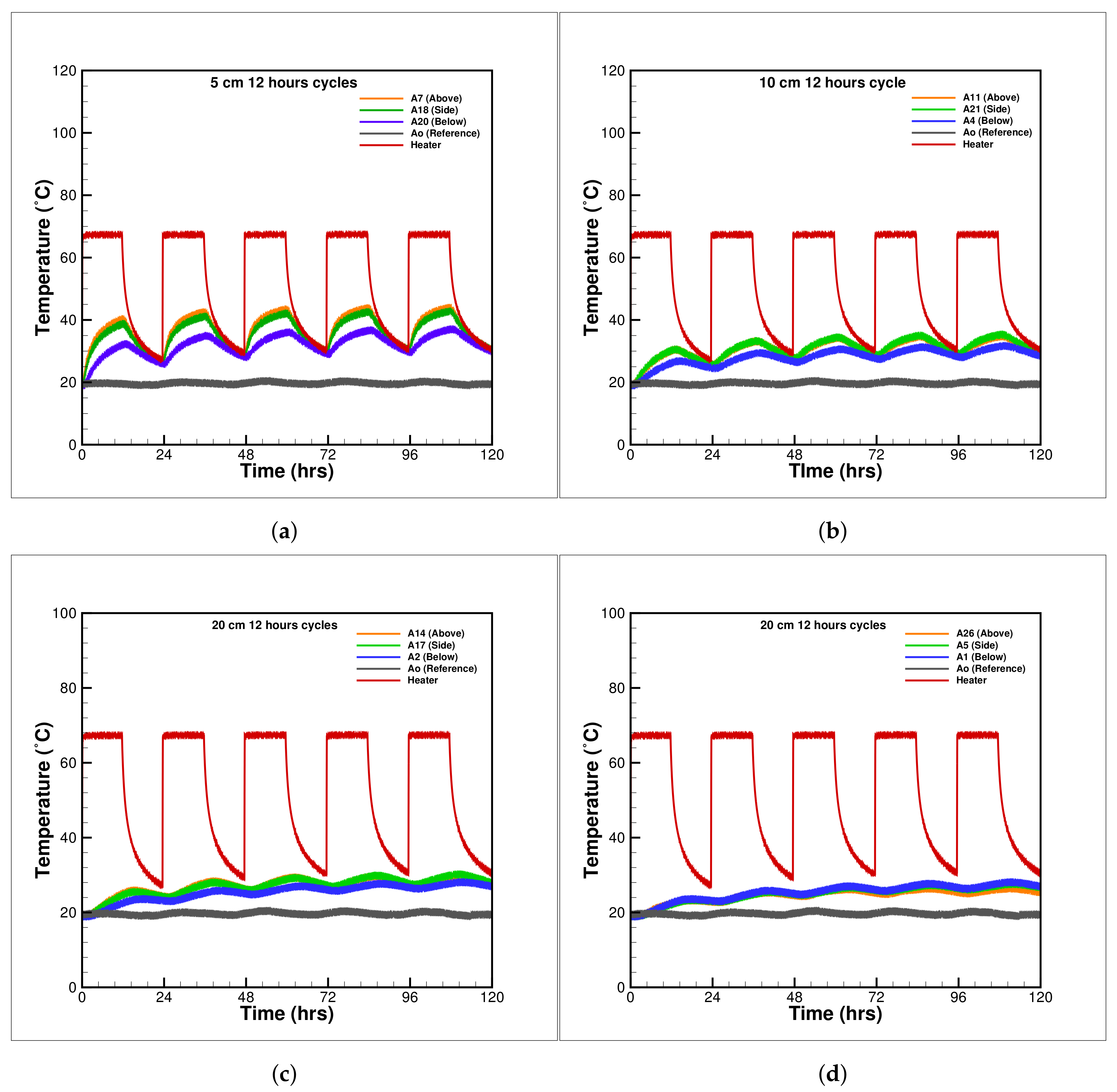
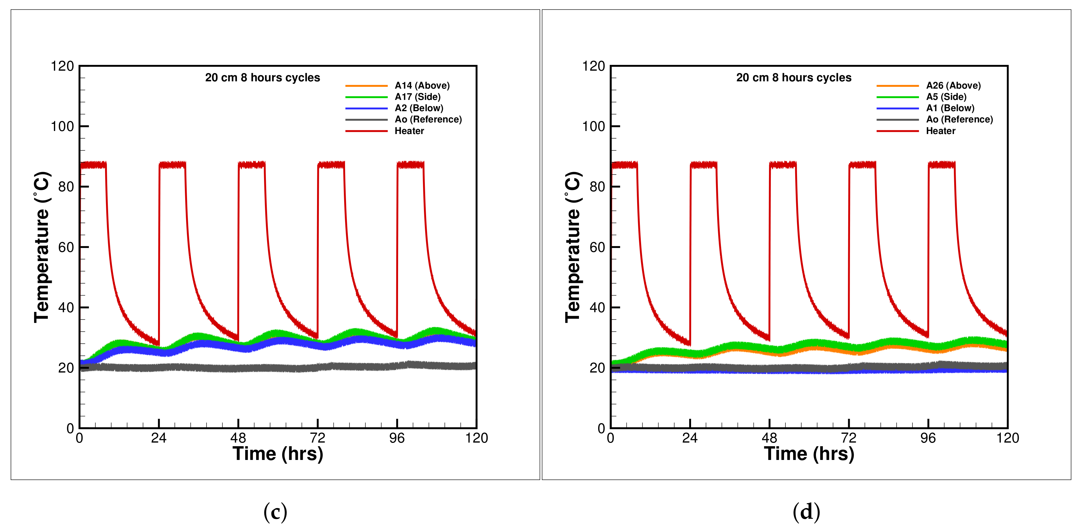
5.1.2. Cyclic Thermal Loading

Figure 8a–d and Figure 9a–d show the cyclic thermal behaviour of the surrounding soil with heater temperature fixed at 70 ℃ and 90 ℃. The underground power cables experience fluctuations in the amount of current due to variable power consumption demand and non uniform power generation from renewable sources such as wind, solar and tides. Previous studies focused on the long term thermal behaviour around the cables with static thermal loading. However, the results in Figure 8 and Figure 9 show a permanent thermal charging of the soil with cyclic loading raise the surrounding temperature with each cycles. The effect is more severe near the cable but visible in the far-field as well. The intensity of charging is also enhances with the rise in heater temperature from 70 to 90 ℃. A similar tendency is observed here with channelisation of heat in the vertical direction and more heating of the soil above the heater.

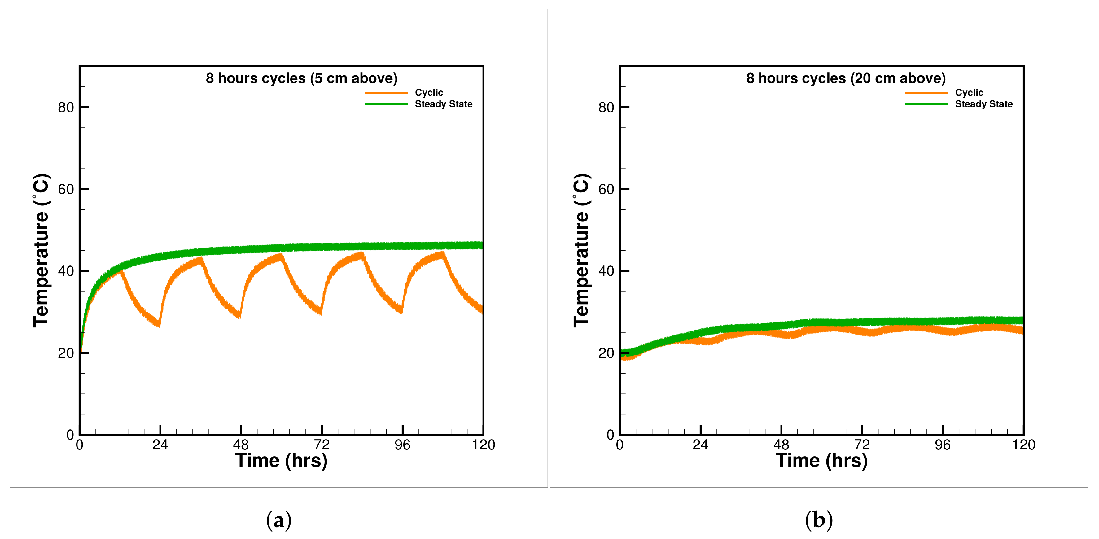
5.1.3. Comparison between Cyclic and Steady State

Figure 10a,b compares temperatures for steady and cyclic heating of the sand for 5 cm and 20 cm thermocouples above the heater, respectively. The thermal charging effect is visible in both cases as the relaxation time is insufficient to cool the system to its original state. The maximum temperature difference in cyclic and steady-state is more significant at the 5cm thermocouple (Figure 10a) and diminishes in the far-field at 20 cm distance (Figure 10b). It is also observed that the steady-state corresponds to the maximum possible temperature around the heater. However, the thermal cyclic heating of short duration is sufficient to heat the soil to a similar maximum temperature that of the static loading scenario.

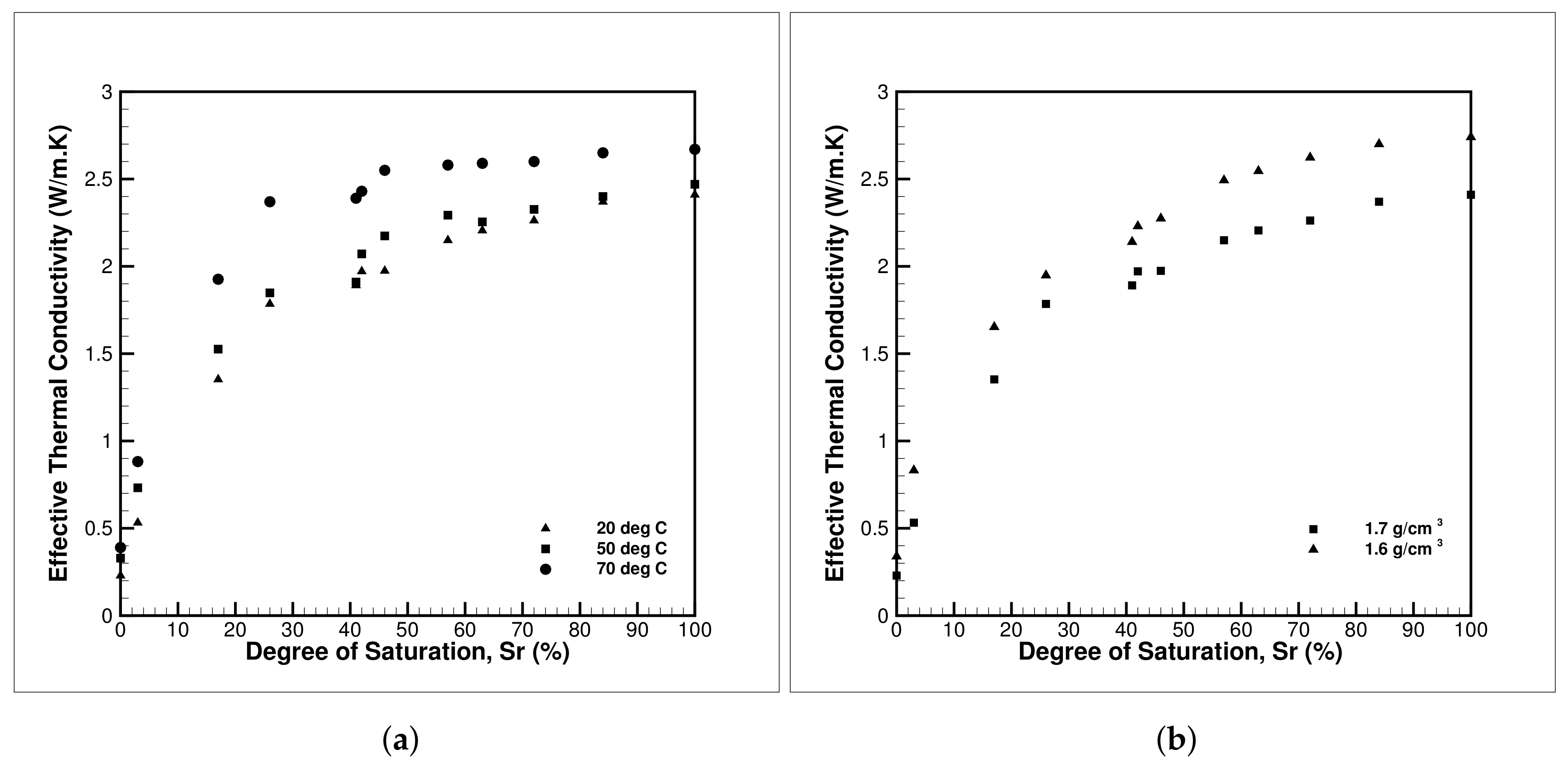
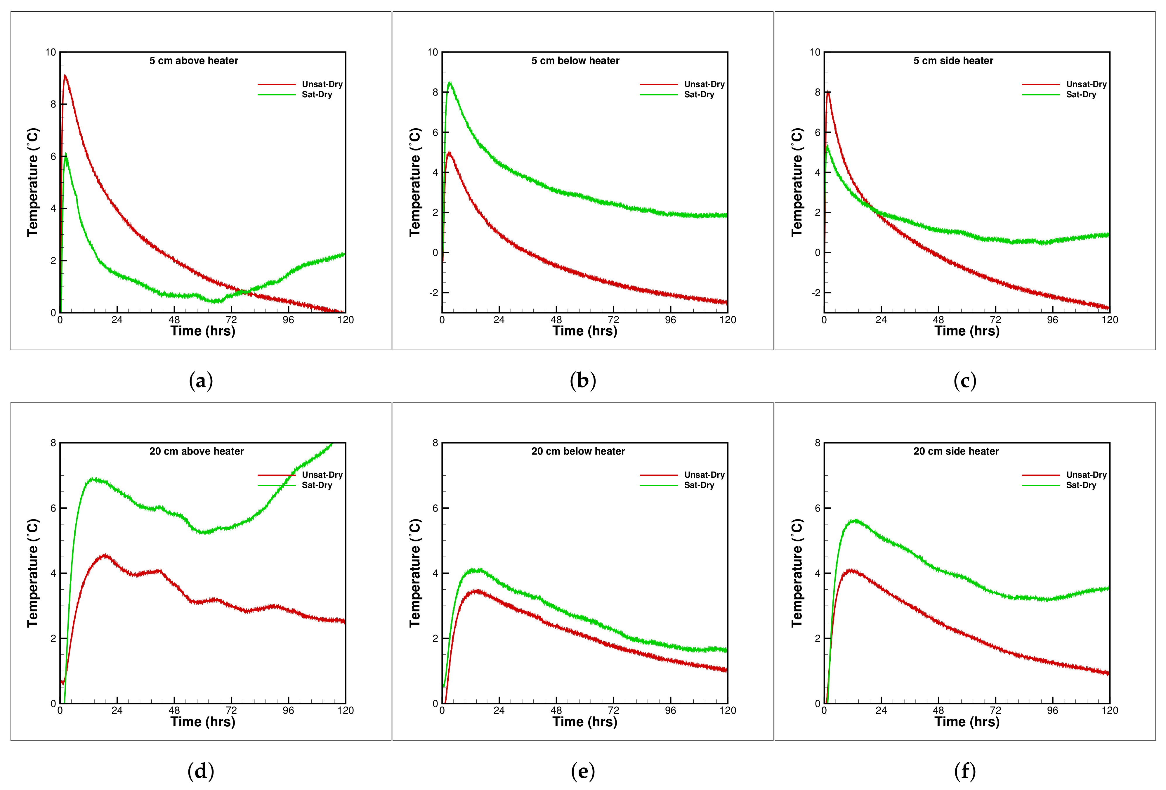
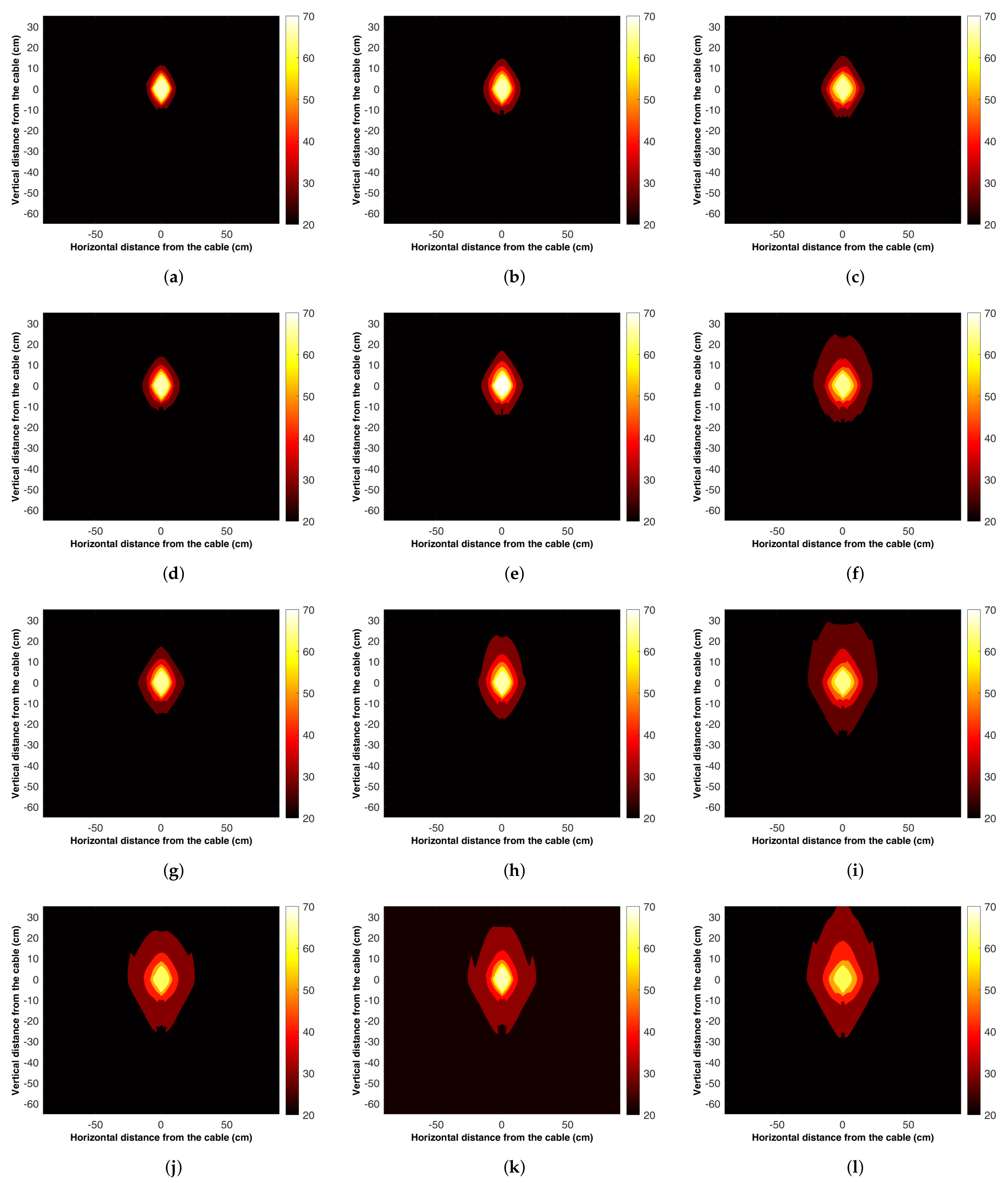
5.2. Static Thermal Experiment for Full Range of Saturation

Figure 11a–f show the temperature difference of saturated and dry case(Sat-Dry) and unsaturated and dry case(Unsat-Dry) around the heater at 5 cm and 20 cm distances, respectively. The saturated and dry(Sat-Dry) difference above the heater at 5 cm and 20 cm show the formation of density-driven convection flow after 72 h of heating. However, the same is absent for (Unsat-Dry) difference graphs at both locations. The thermal buoyancy effect is visible at side thermocouples shown in Figure 11c,f at 5 cm and 20 cm distance from the heater. The thermal buoyancy effect is not considered in the thermal calculation of the power cables as it is assumed that the surrounding soil attains unsaturated condition after a precipitation event quickly. However, the assumption is valid for most cases but fails when the groundwater table is very shallow, or during prolonged periods of rainfall flooding.
Figure 11b,e shows the temperature below the heater at 5 cm and 20 cm, respectively. Figure 11b shows a significant difference between saturated and unsaturated condition; however, the trend is similar in both cases. The effect of thermal buoyancy is visible at 5 cm in saturated sand, and a significant difference is observed between the Sat-Dry and Unsat-Dry lines. The gap between the lines in Figure 11e is minimal, showing no convection cell formation below the heater at 20 cm depth for saturated sand.
Figure 12 is arranged in 3 columns representing the dry, unsaturated and saturated colour map. The four rows show the instances at 3, 6, 12 and 120 h of heating. The colour maps for the dry sand show inefficient heat dissipation and a hot spot around the heater. A comparison of the heat bulb of all cases shows its growth with time for all saturation conditions. After 120 h of heating, convection cell heating is visible for the fully saturated sand where the heat flame bulges outwards (Figure 12l). The observation reinforces and clearly shows the formation of convective heating driven by density difference from experimental measurements. Some irregularities are visible in all these figures due to a limited number of data points from which cubic interpolation is applied to generate the colour maps.

5.3. Discussion on Moisture Transfer in Soil

Water in the soil exists in complex dynamic equilibrium in various states, and the water oscillates between vapour and liquid states and in various forms of water in porous media, namely the hygroscopic, capillary and gravity water. For the saturated case, the vapour phase is absent, and most of the heat transfer is through conduction and some convection that depends on the pore size. However, a complex, fragile equilibrium exists within a soil volume at a uniform temperature, and water molecules will diffuse back and forth from one place to another. The migration of water due to a thermal gradient in the saturated case is buoyancy-driven density difference flow, but for the unsaturated case, it is more of a transient redistribution and not a continuous flow. Furthermore, it might exist in any of the several states for the unsaturated case and migrate by the continuous change of states.
The thermal gradient induced migration in unsaturated soil, studied with an initial uniform moisture content of the soil, reveals that the phenomenon noticeably occurs only over a range of moisture content bounded by two distinct water limits and attains a well-defined maximum. The literature defines the lower limit as the hygroscopic coefficient and the upper limit as the field capacity. The maximum water transfer occurs near the welting point. The range of capillary water well defines all these limits.
Although no drying of soil is observed around the heater in unsaturated conditions, the literature indicates moisture change due to vapour transfer resulting from the difference in partial pressures between vapour in the warmer and in the cooler zones. A longer heating time is required to set up the net movement of vapour towards the cooler zones. The drying process and models and theories devolved for the porous media comes in many flavours ranging from simple diffusion theory and complex ones like the receding front theory, Krischer’s theory, the champion work of Philip and de Vries, Luikov’s theory, and finally, Whitaker’s model, in which all mass, heat transport, and phase change and evaporation are considered. All the work mentioned earlier are material-specific, and the application of soil ranging from complex clay structure to granular sand is trivial. Therefore, large scale experiments still hold the key for proper identification and understanding of the unsaturated heat transfer mechanism, which is prevalent in nature.

6. Conclusions

This paper presents experimental findings of temperature rise around a heated cylinder representing an underground power cable. XRD and XRF studies are performed for the chemical composition and mineral identification of the sand used around the cylinder and were found to be made up of more than 98 % quartz. The thermal properties of sand are tested with a standard KD2 pro device, and the effect of varying density, saturation, and temperature is studied for the sand. These parameters show a nonlinear positive dependence on the thermal conductivity of the sand. A series of large-scale tests with cylindrical heating is performed with static and cyclic thermal loads of 70 ℃ and 90 ℃ for sand in the dry condition, which correlates to the worst case for power cable insulation melt. The cyclic thermal test shows the thermal charging of sand for both temperature conditions. A comparison of the static and cyclic cases shows that static thermal loading corresponds to maximal temperature rise in both near and far-fields irrespective of the thermal charging of cyclic loads. The static thermal test at 70 ℃ heat temperature and varying saturation show a positive heat dissipation effect due to enhanced thermal conductivity of the wet sand. 1D and 2D plots show thermal buoyancy effect and heat channelisation above the heater for full and partial saturated sand in near and far-fields. However, convective heating has been absent below the heater. This study is anticipated to be a progenitor in the development of UPC systems to fodder and support the promising green energy infrastructure.

Author Contributions

Conceptualisation, S.A., Z.H.R., V.T. and F.W.; methodology, Z.H.R. and V.T.; software, S.A., Z.H.R. and S.I.; experimental investigation, S.A., J.C.C.A. and Z.H.R.; resources, F.W. and V.T.; data curation, S.A., S.I. and Z.H.R.; writing—original draft preparation, S.A., V.T. and Z.H.R.; writing—review and editing, Z.H.R. and V.T.; visualisation, S.A. and Z.H.R.; supervision, Z.H.R. and F.W.; project administration, Z.H.R. and F.W.; funding acquisition, F.W. and V.T. All authors have read and agreed to the published version of the manuscript.

Funding

Z.H.R. and F.W. would like to thank project DuoFill grant BMWi/KF3067303KI3 funded by Federal ministry for Energy, Germany. V.T. and S.I. gratefully acknowledge the Deanship of Scientific Research, King Khalid University, Abha, Kingdom of Saudi Arabia, project grant number RGP.2/58/42. We acknowledge financial support by Land Schleswig-Holstein within the funding programme Open Access Publikationsfonds.

Institutional Review Board Statement

Not applicable.

Informed Consent Statement

Not applicable.

Data Availability Statement

The data published in the paper is available upon personal request from the corresponding author.

Acknowledgments

S.A. would like to thanks AMU Alumni scholarship for funding their travel and stay in Germany.The authors thankfully acknowledge the Deanship of Scientific Research, King Khalid University, Abha, Kingdom of Saudi Arabia, for funding this work under the grant number RGP.2/58/42. We acknowledge financial support by Land Schleswig-Holstein within the funding programme Open Access Publikationsfonds.

Conflicts of Interest

The authors declare no conflict of interest.

Abbreviations

The following abbreviations are used in this manuscript:
avolumetric air content
c, C p specific heat [J kg 1 K 1 ]
Cvolumetric heat capacity [J m 3 K 1 ]
Ddiffusion coefficient of water vapour in air [m 2 s 1 ]
D T macroscopic diffusivity for moisture transport due to T [m 2 s 1 K 1 ]
D θ macroscopic diffusivity for moisture transport due to θ 1 [m 2 s 1 ]
eempirical factor
gacceleration due to gravity [ms 2 ]
hrelative humidity
Hspecific enthalpy [J kg 1 ]
Ttemperature [K]
x , y horizontal coordinate [m]
zvertical coordinate, positive downward [m]
Greek Symbols
ε low value of θ l
ζ ( T ) a / T
θ volumetric moisture content
λ Effective thermal conductivity [W m 1 K 1 ]
ψ moisture potential [m]
ρ density [kgm 3 ]
Subscripts
0reference value
aair
ddrying
hheat
kcritical
lliquid
mmoisture
Mmatrix
rreversal
ssaturation
vvapour
wwetting

References

  1. Oclon, P.; Pobedza, J.; Walczak, P.; Cisek, P.; Vallati, A. Experimental Validation of a Heat Transfer Model in Underground Power Cable Systems. Energies 2020, 13, 1747. [Google Scholar] [CrossRef] [Green Version]
  2. Ahmad, S.; Rizvi, Z.H.; Khan, M.A.; Ahmad, J.; Wuttke, F. Experimental study of thermal performance of the backfill material around underground power cable under steady and cyclic thermal loading. Mater. Today Proc. 2019, 17, 85–95. [Google Scholar] [CrossRef]
  3. Francis, E.C.; Shelley, O.P. Copper wire theft and high voltage electrical burns. Int. J. Burn. Trauma 2014, 4, 59–61. [Google Scholar]
  4. Van Dyke, P.; Havard, D.; Laneville, A. Effect of Ice and Snow on the Dynamics of Transmission Line Conductors. In Atmospheric Icing of Power Networks; Farzaneh, M., Ed.; Springer: Dordrecht, The Netherlands, 2008; pp. 171–228. [Google Scholar] [CrossRef]
  5. Yuan, S.; Li, P.; Nie, L. Study on Electromagnetic Radiation of Ultra-High Voltage Power Transmission Line. In Proceedings of the International Conference on Computer Science and Information Technology, Singapore, 29 August–2 September 2008; pp. 402–406. [Google Scholar]
  6. International Standard IEC 60287-2-1, Electric Cables—Calculation of the Current Rating—Part 2-1: Thermal Resistance—Calculation of the Thermal Resistance; IEC: Geneva, Switzerland, 2014.
  7. IEEE Std 835-1994 Standard Power Cable Ampacity Tables. 1994. Available online: https://standards.ieee.org/standard/835-1994.html (accessed on 17 October 2021).
  8. Calcara, L.; Sangiovanni, S.; Pompili, M. MV underground cables: Effects of soil thermal resistivity on anomalous working temperatures. In Proceedings of the AEIT International Annual Conference, Cagliari, Italy, 20–22 September 2017; pp. 1–5. [Google Scholar] [CrossRef]
  9. Gouda, O.E.; Osman, G.F.A.; Salem, W.A.A.; Arafa, S.H. Cyclic Loading of Underground Cables Including the Variations of Backfill Soil Thermal Resistivity and Specific Heat With Temperature Variation. IEEE Trans. Power Deliv. 2018, 33, 3122–3129. [Google Scholar] [CrossRef]
  10. Salata, F.; Nardecchia, F.; Gugliermetti, F.; de Lieto Vollaro, A. How thermal conductivity of excavation materials affects the behavior of underground power cables. Appl. Therm. Eng. 2016, 100, 528–537. [Google Scholar] [CrossRef]
  11. De Leon, F.; Anders, G.J. Effects of backfilling on cable ampacity analyzed with the finite elements method. IEEE Trans. Power Deliv. 2008, 23, 537–543. [Google Scholar] [CrossRef]
  12. Wan, H.; Xia, J.; Zhang, L.; She, D.; Xiao, Y.; Zou, L. Sensitivity and Interaction Analysis Based on Sobol Method and Its Application in a Distributed Flood Forecasting Model. Water 2015, 7, 2924–2951. [Google Scholar] [CrossRef] [Green Version]
  13. Philip, J.R.; de Vries, D.A. Moisture Movement in Porous Materials under Temperature Gradients. Trans. Am. Geophys. Union 1957, 38, 222–232. [Google Scholar] [CrossRef]
  14. De Vries, D.A. The theory of heat and moisture transfer in porous media revisited. Int. J. Heat Mass Transf. 1987, 30, 1343–1350. [Google Scholar] [CrossRef]
  15. Jackson, R.D.; Kimball, B.A.; Reginato, R.J.; Idso, S.B.; Nakayama, F.S. Heat and Mass Transfer in the Biosphere. In Transfer Processes in Plant Environment; De Vries, D.A., Afgan, N.H., Eds.; Scripta: Washington, DC, USA, 1975; pp. 67–76. [Google Scholar]
  16. Crausse, P. Fundamental Study of Heat and Humidity Couple Transfers in Unsaturated Environments. Ph.D. Thesis, Institut National Polytechnique de Toulouse, Toulouse, France, 1983. (In French). [Google Scholar]
  17. Moya, R.E.S.; Prata, A.T.; Cunha Neto, J.A.B. Experimental analysis of unsteady heat and moisture transfer around a heated cylinder buried into a porous medium. Int. J. Heat Mass Transf. 1999, 31, 1076–1087. [Google Scholar] [CrossRef]
  18. Kowalski, S.J.; Pawłowski, A. Modeling of kinetics in stationary and intermittent drying. Dry. Technol. Int. J. 2010, 28, 1023–1031. [Google Scholar] [CrossRef]
  19. Himasekhar, K.; Bau, H.H. Thermal Convection Around a Heat Source Embedded in a Box Containing a Saturated Porous Medium. J. Heat Transf. 1988, 110, 649–654. [Google Scholar] [CrossRef]
  20. Enescu, D.; Colella, P.; Russo, A.; Porumb, R.F.; Seritan, G.C. Concepts and Methods to Assess the Dynamic Thermal Rating of Underground Power Cables. Energies 2021, 14, 2591. [Google Scholar] [CrossRef]
  21. Tang, F.; Nowamooz, H. Outlet temperatures of a slinky-type Horizontal Ground Heat Exchanger with the atmosphere-soil interaction. Renew. Energy 2020, 146, 705–718. [Google Scholar] [CrossRef]
  22. Wessolek, G.; Bertermann, D.; Schwarz, H.; Stegner, J. Interaktionen des Erdkabelsystems SuedLink mit der Kabelumgebung; FAU University Press: Erlangen, Germany, 2020; (In German). [Google Scholar] [CrossRef]
  23. Neher, J.H.; McGrath, M.H. The calculation of the temperature rise and load capability of cable systems. in Transactions of the American Institute of Electrical Engineers. Part III: Power Apparatus and Systems. AIEE Trans. 1957, 76, 752–764. [Google Scholar] [CrossRef]
  24. Sellers, S.M.; Black, W.Z. Refinements to the Neher-McGrath model for calculating the ampacity of underground cables. IEEE Trans. Power Deliv. 1996, 11, 12–30. [Google Scholar] [CrossRef]
  25. Kroener, E.; Vallati, A.; Bittelli, M. Numerical simulation of coupled heat, liquid water and water vapor in soils for heat dissipation of underground electrical power cables. Appl. Therm. Eng. 2014, 70, 510–523. [Google Scholar] [CrossRef]
  26. Faulkner, R.W. Underground HVDC transmission via elpipes for grid security. In Proceedings of the IEEE Conference on Technologies for Homeland Security, Waltham, MA, USA, 13–15 November 2012; pp. 359–364. [Google Scholar] [CrossRef]
  27. Jury, W.A. Simultaneous Transport of Heat and Moisture through a Medium Sand. Ph.D. Thesis, University of Wisconsin-Madison, Madison, WI, USA, 1973. [Google Scholar]
  28. Ocłoń, P.; Bittelli, M.; Cisek, P.; Kroener, E.; Pilarczyk, M.; Taler, D.; Rao, R.V.; Vallati, A. The performance analysis of a new thermal backfill material for underground power cable system. Appl. Therm. Eng. 2016, 108, 233–250. [Google Scholar] [CrossRef]
  29. Marshall, J.S.; Fuhrmann, A.P. Effect of rainfall transients on thermal and moisture exposure of underground electric cables. Int. J. Heat Mass Transf. 2015, 80, 660–672. [Google Scholar] [CrossRef]
  30. International Standard IEC—TR 62095 Electric Cables Calculations for Current Ratings Finite Element Method; IEC: Geneva, Switzerland, 2003.
  31. Lewis, R.W.; Morgan, K.; Thomas, H.R.; Seetharamu, K.N. The Finite Element Method in Heat Transfer Analysis; Wiley: Hoboken, NJ, USA, 1996. [Google Scholar]
  32. Hruška, M.; Clauser, C.; De Doncker, R.W. Influence of dry ambient conditions on performance of underground medium-voltage DC cables. Appl. Therm. Eng. 2019, 149, 1419–1426. [Google Scholar] [CrossRef]
  33. Freire, J.; Freire, F.; Perazzini, H. On the Influence of Particles Characteristics on Moisture Diffusivity during Drying of Granular Porous Media. Adv. Chem. Eng. Sci. 2014, 4, 7–16. [Google Scholar] [CrossRef] [Green Version]
  34. Meili, L.; Perazzini, H.; Ferreira, M.; Freire, J.T. Analyzing the universality of the dimensionless vibrating number based on the effective moisture diffusivity and its impact on specific energy consumption. Heat Mass Transf. 2020, 56, 1659–1672. [Google Scholar] [CrossRef]
  35. Groeneveld, G.J.; Snijders, A.L.; Koopmans, G.; Vermeer, J. Improved method to calculate the critical conditions for drying out sandy soils around power cables. IEE Proc. C Gener. Transm. Distrib. 1984, 131, 42–53. [Google Scholar] [CrossRef]
  36. Ainhirn, F.; Woschitz, R.; Bolzer, A. Extended Approach for Calculating Thermal Stress and Ampacity of High Voltage Cable Systems Based on Experimental Data. In Proceedings of the Jicable 2019: 10th International Conference On Insulated Cables—Versailles, Versailles, France, 23–27 June 2019; pp. 1–6. [Google Scholar]
  37. Adams, J.I. The Thermal Behavior of Cable Backfill Materials. IEEE Trans. Power Appar. Syst. 1968, 87, 1149–1161. [Google Scholar] [CrossRef]
  38. Trinks, J. Einfluss des Wasser- und Wärmehaushaltes von Böden auf den Betrieb Erdverlegter Energiekabel. Ph.D. Thesis, Technical University Berlin, Berlin, Germany, 2010. (In German). [Google Scholar]
  39. Ainhirn, F. Environmental Parameter Modelling for Thermal Rating Calculations of Power Cables in Urban Areas using Machine Learning and Big Data. In Proceedings of the 2020 IEEE International Smart Cities Conference (ISC2), Piscataway, NJ, USA, 28 September–1 October 2020; pp. 1–7. [Google Scholar]
  40. De Lieto Vollaro, R.; Fontana, L.; Vallati, A. Experimental study of thermal field deriving from an underground electrical power cable buried in non-homogeneous soils. Appl. Therm. Eng. 2014, 62, 390–397. [Google Scholar] [CrossRef]
  41. Hartley, J.G.; Black, W.Z. Transient Simultaneous Heat and Mass Transfer in Moist, Unsaturated Soils. J. Heat Transf. Am. Soc. Mech. Eng. Digit. Collect. 1981, 103, 376–382. [Google Scholar] [CrossRef]
  42. Chatzipanagiotou, P.; Chatziathanasiou, V.; de Mey, G.; Wiecek, B. Influence of soil humidity on the thermal impedance, time constant and structure function of underground cables: A laboratory experiment. Appl. Therm. Eng. 2017, 113, 1444–1451. [Google Scholar] [CrossRef]
  43. Freitas, D.S.; Prata, A.T.; de Lima, A.J. Thermal performance of underground power cables with constant and cyclic currents in presence of moisture migration in the surrounding soil. IEEE Trans. Power Deliv. 1996, 11, 1159–1170. [Google Scholar] [CrossRef]
  44. Williams, J.A.; Parmar, D.; Conroy, M.W. Controlled backfill optimization to achieve high ampacities on transmission cables. IEEE Trans. Power Deliv. 1994, 9, 544–552. [Google Scholar] [CrossRef]
  45. Verschaffel-Drefke, C.; Schedel, M.; Balzer, C.; Hinrichsen, V.; Sass, I. Heat Dissipation in Variable Underground Power Cable Beddings: Experiences from a Real Scale Field Experiment. Energies 2021, 14, 7189. [Google Scholar] [CrossRef]
  46. Rasoulpoor, M.; Mirzaie, M.; Mirimani, S.M. Thermal assessment of sheathed medium voltage power cables under non-sinusoidal current and daily load cycle. Appl. Therm. Eng. 2017, 123, 353–364. [Google Scholar] [CrossRef]
  47. Gouda, O.E.; Osman, G.F.A. Enhancement of the thermal analysis of power cables installed in polyvinyl chloride (PVC) ducts under continuous and cyclic current loading conditions. IET Gener. Transm. Distrib. 2021, 15, 1144–1158. [Google Scholar] [CrossRef]
  48. Rizvi, Z.H.; Zaidi, H.H.; Akhtar, S.J.; Sattari, A.S.; Wuttke, F. Soft and hard computation methods for estimation of the effective thermal conductivity of sands. Heat Mass Transf. 2020, 56, 1947–1959. [Google Scholar] [CrossRef]
  49. He, H.; He, D.; Jin, J.; Smits, K.M.; Dyck, M.; Wu, Q.; Si, B.; Lv, J. Room for improvement: A review and evaluation of 24 soil thermal conductivity parameterization schemes commonly used in land-surface, hydrological, and soil-vegetation-atmosphere transfer models. Earth Sci. Rev. 2020, 211, 1–21. [Google Scholar] [CrossRef]
  50. Campbell, G.S.; Jungbauer, J.D.; Bidlake, J.R.; Hungerford, R.D. Predicting the effect of temperature on soil thermal conductivity. E3S Web Conf. 2020, 195, 04007. [Google Scholar] [CrossRef]
  51. Aljundi, K.; Vieira, A.; Maranha, J.; Lapa, J.; Cardoso, R. Effects of temperature, test duration and heat flux in thermal conductivity measurements under transient conditions in dry and fully saturated states. Soil Sci. 1994, 158, 307–313. [Google Scholar] [CrossRef]
Figure 1. Interaction of underground power cables with surrounding soil and environments and different modes of heat and mass transfer in the soil mass.
Energies 14 08191 g001
Figure 2. XRD of sand the corresponds to Quartz mineral (blue) and trace amount of other minerals.
Energies 14 08191 g002
Figure 3. The experimental setup with (a) Schematic diagram of heating control unit and thermocouple arrangement with data acquisition unit; (b) large scale box setup showing heating and temperature control unit.
Energies 14 08191 g003
Figure 4. Physical properties of sand (a) particle size distribution of sand; (b) thermal conductivity measurements at different dry densities of sand.
Energies 14 08191 g004
Figure 5. Thermal properties of sand (a) plot of thermal conductivity vs. saturation for three different temperature values of 20 ℃, 50 ℃ and 70 ℃; (b) saturation dependent thermal conductivity at two density values.
Energies 14 08191 g005
Figure 6. Temperature plot with 5 days constant temperature heating of 70 ℃ of thermocouples at (a) 5 cm; (b) 10 cm; (c) 15 cm; (d) 20 cm from the heater surface.
Energies 14 08191 g006
Figure 7. Temperature plot with 5 days constant temperature heating of 90 ℃ of thermocouples at (a) 5 cm; (b) 10 cm; (c) 15 cm; (d) 20 cm from the heater surface.
Energies 14 08191 g007
Figure 8. Temperature plot with 5 days cyclic 12 h heating and 12 h cooling of 70 ℃ at (a) 5 cm; (b) 10 cm; (c) 15 cm; (d) 20 cm from the heater surface.
Energies 14 08191 g008
Figure 9. Temperature plot with 5 days cyclic 12 h heating and 12 h cooling of 90 ℃ at (a) 5 cm; (b) 10 cm; (c) 15 cm; (d) 20 cm from the heater surface.
Energies 14 08191 g009aEnergies 14 08191 g009b
Figure 10. Comparison between cyclic and steady state heating condition at 70 ℃ (a) 5 cm; (b) 20 cm from the heater surface.
Energies 14 08191 g010
Figure 11. The differences in temperature between the unsaturated-dry and saturated-dry soil conditions at a depth of 5 cm and 20 cm. (a) 5 cm of the top surface of heater; (b) 5 cm in the horizontal line of heater; (c) 5 cm of the bottom surface of heater; (d) 20 cm of the top surface of heater; (e) 20 cm in the horizontal line of heater; (f) 20 cm of the bottom surface of heater.
Energies 14 08191 g011
Figure 12. Colour map of temperature distribution around the heater and evolution of temperature field with heating for dry, unsaturated and saturated sand, after 3 hours (ac), 6 hours (df), 12 hours (gi), and 72 hours (jl).
Energies 14 08191 g012
Table 1. XRF results for the sand.
Weight Percent Oxides of the Soil Sample
CompoundSiO 2 Al 2 O 3 Fe 2 O 3 CaOMgOK 2 O
Percentage98.278190.5933430.5789480.040280.0982820.019334
Publisher’s Note: MDPI stays neutral with regard to jurisdictional claims in published maps and institutional affiliations.

