Article

A Linear Hybrid Concentrated Photovoltaic Solar Collector: A Methodology Proposal of Optical and Thermal Analysis

by
Eduardo Venegas-Reyes
1,
Naghelli Ortega-Avila
2,*,
Manuel I. Peña-Cruz
3,
Omar J. García-Ortiz
4 and
Norma A. Rodríguez-Muñoz
2
1
IMTA-Instituto Mexicano de Tecnología del Agua, Paseo Cuauhnáhuac 8532, Progreso, Jiutepec 62550, Morelos, Mexico
2
CONACYT-Centro de Investigación en Materiales Avanzados S.C., Calle CIMAV 110, Ejido Arroyo Seco 34147, Durango, Mexico
3
CONACYT-Centro de Investigaciones en Óptica A.C., Unidad Aguascalientes, Prol. Constitución 607, Aguascalientes 20200, Aguascalientes, Mexico
4
Departamento de Ingeniería Sustentable, Centro de Investigación en Materiales Avanzados S.C., Calle CIMAV 110, Ejido Arroyo Seco 34147, Durango, Mexico
*
Author to whom correspondence should be addressed.
Energies 2021, 14(23), 8155; https://doi.org/10.3390/en14238155
Submission received: 28 October 2021 / Revised: 25 November 2021 / Accepted: 2 December 2021 / Published: 5 December 2021
(This article belongs to the Special Issue Volume II: Research on Solar Collector)

Abstract

:
The photovoltaic cell surface in linear hybrid concentrated solar collectors receives non-uniform radiative flux, causing additional thermal stress due to hot spots and reducing its electrical performance and durability. The current study proposes a parametric methodology to determine the optimal receiver displacement required in a linear Cassegrain-type hybrid solar collector. The aim was to achieve a minimal non-uniformity distribution and a high radiative flux over the photovoltaic cells, considering optical errors close to real environment conditions and analyzing the heat transfer to determine the electrical and thermal efficiencies. The developed methodology was applied to analyze a case study with a receiver width of 0.125 m and rim angle of 80° and using a commercial silicon photovoltaic cell that supports up to 7000 W/m2. After applying the methodology, a hybrid solar collector with a concentration ratio of 13.0 and receiver displacement of 0.14 m is recommended. As a result, 5728 W/m2 of average radiative flux with non-uniformity lower than 4% was achieved. Thus, thanks to the proposed configuration, a low non-uniformity and high radiative flux were achieved, benefiting the photovoltaic cells’ life while improving their operation.

1. Introduction

Energy is vital for human life and industrial development; in the following decades, efforts to balance the increased energy demand with sustainable living on the planet will be essential. Worldwide, 14,821 Mtoe of total primary energy supply and 25,027 TWh were used in 2019, representing an increase of 56.46% since 1990 [1]. Thus the interest in increasing the implementation of renewable energies sustainably in the energy mix, where the most ambitious plans include a net-zero emissions energy sector by 2050 [2].
Among the possibilities to use renewable energy, solar energy appears to be a solid alternative to cover an essential fraction of the global energy demand. In 2020, 65% of the electricity demand growth was achieved with renewable energy technologies [3]. Meanwhile, within the Stated Policies Scenario, the renewable electricity generation was 7593 TWh (28%); from this, 833 TWh was photovoltaics (PV) and 13 TWh was of concentrating solar power (CSP) [3].
The technology related to hybrid photovoltaic/thermal collectors (PV/T) has significant development over the past years. On their own, both technologies are considered mature to exploit solar energy. Nevertheless, various designs were proposed to enhance the PV cells’ lifetime, avoiding their overheating through regular heat removal, which improves the PV electric output and allows taking advantage of thermal energy. Currently, some works can be consulted on the most novel and relevant design proposals of PV/T systems. For instance, Besheer et al., 2016, deepened into structural and geometric designs that dominate the current research developments [4]. At least 30 distinct geometries that pledge to improve the typical PV/T energy output were proposed, and the main determinants that influence the performance were found out. For example, using a top cover, some methods to reduce long-wavelength radiation losses, or manufacturing special designs such as honeycomb channels behind the PV receiver allow achieving thermal efficiencies above 85%. On the other hand, solar cell shading, temperature, and radiation flux uniformity influence the PV/T electrical efficiency. In the same sense, Yazdanifard and Ameri, 2018, [5] performed a review based on solar equipment’s exergetic and energetic performance to establish a comparison base between electricity and thermal energy quality production that provides this type of system; they found that the exergetic efficiency of the PV/T systems increases with the solar flux so that the concentrating geometries application could be advantageous. Thus, a PV/T collector could be improved using an optical concentrator to raise the intensity of illumination on the receiver, where a high-efficiency solar cell can be placed; this configuration is known as a concentrated photovoltaic/thermal (CPV/T) hybrid system.
Correspondingly, Ju et al., 2017, [6] presented a review of spectral beam splitting technology CPV/T systems. The authors remarked that CPV/T technology allows heating the thermal fluid until temperatures higher than 80 °C and, although it requires solar tracking, the reduction in the area due to the concentration compensates for its higher cost. They stressed that most of the investigations focused on novel design concepts and numerically analyzing their performance. Hence, there are different numerical studies where mathematical models are proposed to be either applied for design or dimensioning purposes [7,8,9,10,11,12,13,14,15], while others are focused on developing methodologies to evaluate the performance of the systems [16,17,18,19,20,21].
Gomaa et al., 2020, [9] performed an analysis to calculate the efficiency of a concentrating photovoltaic/thermal collector (CPV/T) and its validation under various operation conditions. Herrando et al., 2019, [22] made 26 design proposals for the absorber-exchanger of the PV/T solar collectors and compared their performance against a reference case. Othman and Othman et al., 2017, [11] and Othman et al., 2015, [14] presented the design, manufacture, evaluation, and validation of conventional and single-pass PV/T solar collectors. The research improved the efficiency of the production of electric and thermal energy. Wang et al., 2020, [15] presented a solar concentrating PV and thermal combined system with a compact concentrator and beam splitter, achieving a high concentration uniformity. Nasseriyan et al., 2020, [23] investigated through computational fluid dynamics (CFD) and experimentation of a novel proposal of an asymmetric CPC-PVT solar collector and found that the tilt angle impact is more relevant to the thermal production. Moreover, by applying insulation to the back of the reflector, the thermal power rises by 3%, and when the front glass is removed, the electrical yield increases by 2%.
Cabral et al., 2021, [24] experimented with a CPVT collector coupled with a PVT wedge receiver, where the position of the wedge receiver resulted in being highly sensitive to high incidence angles. Gorouh et al., 2022, [21] developed a zero-dimensional thermal model for a low concentration CPVT collector investigating the effect of the heat transfer fluid (HTF) mass flow rate and found that by increasing the HTF inlet temperature, the thermal and electrical outputs are reduced by 25% and 18% and that the recommended flow rates have to be higher than 0.015 kg/s. Moreover, a dynamic model was developed for a CPV/Concentrating solar power system to describe the solar radiation linear variation for different weather conditions [20]. The developed quasi-steady-state model is applied to understand the daily performance of a hybrid system. The main objective of developing the mathematical model was to size and evaluate a multi-mirror solar CPV/T system [7].
Similarly, Wang et al., 2019, performed an optical and thermodynamic investigation on a multi-segment mirror CPV/T system [25]. The needle optimization method was implemented to design the spectral beam splitter, and the Monte Carlo ray-tracing method was used to simulate the solar concentration process. When the solar cell’s installation height is increased, and the width is reduced, the geometric concentration ratio of the CPV/T is enhanced. As a result, optical efficiencies of 76.3% were calculated.
Herez et al., 2020, [26] presented a compendium, classification, and application of novel PV/T systems regarding novel design concepts. Among their observations are that the main characteristic that must be considered to select the solar collector type is the required temperature in the application, and concerning concentrating systems, they found the electrical efficiency is similar for the different solar concentrator types; however, the most commonly applied geometries are linear Fresnel and parabolic trough. However, Joshi and Dhoble [27] report that parabolic trough collectors are preferred when low concentrations are allowed and that typically, CPV/T electrical and thermal efficiencies are in the ranges of 8% to 11%, and 40% to 60%, respectively.
Furthermore, Sharaf and Orhan published reviews of the essentials, design considerations, performance, and future perspectives on CPV/T systems [28,29]. Additionally, both documents thoroughly discuss the interrelation among the past proposed design methodologies, simplifications, and considerations, application, and possible improvements. They conclude that a critical design variable of CPV/T solar collectors is the concentration ratio optimization, depending on the thermal and electrical requirements [28]. Special attention must be placed on achieving uniform distributions of illumination and temperature over the PV receiver, through suitable optical and energy modeling methods, as ray-tracing and energy balance models, respectively, considering that the electrical and thermal behavior is affected by CPV/T optical performance [29]. In this sense, Alzahrani et al. [30] analyzed the effects of increased solar radiation flux in CPV/T collectors with two main strategies: integrating secondary optics or maximizing the primary optics. Some challenges detected in both solutions are the systems’ complexity and illumination, and temperature non-uniformity. However, secondary optics improve the radiative flux uniformity and reduce the tracking load, although care must be taken that optical efficiency is not affected. Depending on the PV cell type, the electrical and thermal efficiency could increase until values reach nearly 70% and 60%, for concentration ratios lower than ten or between 10 and 100, respectively.
Regarding CPV/T solar collectors with secondary reflectors, a promising configuration is the so-called Cassegrain-type solar concentrator, which has a convergent parabolic primary mirror and a divergent secondary surface located in the focus of the primary mirror. This optical configuration redirects the radiative flux over a final receiver placed between both optical surfaces, with a rectangular flux distribution output more uniform than that of simpler optical systems, ideal for PV cells. Additionally, it allows having a compact optical system with a large focal length and wide acceptance angle [31]. However, the simulation of solar concentrators with secondary optics is challenged to reach an optical configuration with a high concentration ratio and a good intercept factor [32].
This work proposes a simplified parametric methodology for optical analysis, by the ray-tracing technique, of a linear Cassegrain-type CPV/T collector with parabolic-trough reflectors as constituent elements and PV cells located on a flat receiver. This methodology allows achieving good flux non-uniformity, which also provides uniform PV cells’ temperature by adjusting the displacement of the receiver on the focal line of the concentrator. Additionally, the proposed method allows determining the optimal concentration ratio based on the highest radiative flux of the configuration. Finally, this optical methodology is complemented with a heat transfer model in the CPV/T receiver, developed to determine the PV cells and thermal fluid temperatures and the electrical, thermal, and total conversion efficiencies.

2. Materials and Methods

The developed methodology is focused on the optical and thermal analysis of a linear Cassegrain-type CPV/T collector; this is, a parabolic trough collector coupled to a secondary parabolic reflector. The main objective of the optical analysis is to achieve a uniform radiative flux distribution on the receiver (PV cell) to avoid the efficiency losses due to temperature gradients on the surface. The purpose of use concentration in a CPV/T is to achieve a higher temperature in the cooling fluid than a PV/T solar collector without solar concentration, decreasing the use of silicon material and increasing the PV cell efficiency. However, commercial solar cells have a concentration limit that does not exceed 7000 W/m2 [33], so keeping the maximum radiative flux over the receiver below this value is necessary. On the other hand, thermal analysis quantifies the electrical and thermal efficiencies and the temperatures of the PV cells and cooling fluid.

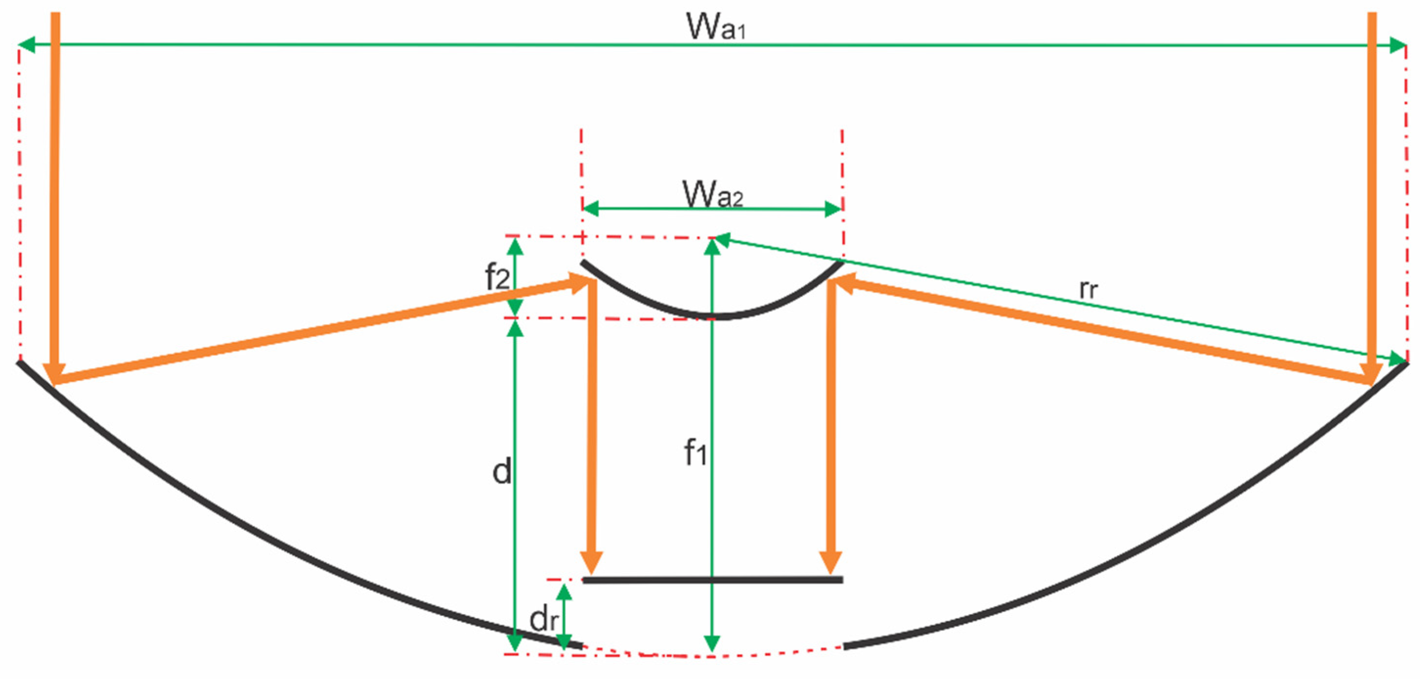
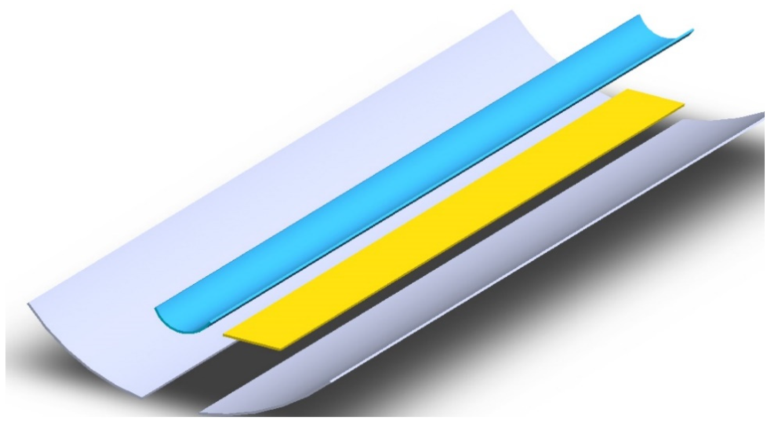
2.1. Geometry and Case Study

The proposed geometry for the linear Cassegrain-type CPV/T collector consists of a parabolic trough primary concentrator (PPC) coupled to a secondary parabolic reflector (SPR), in which the reflective part is on its convex side in such a way that the concentrated rays are reflected into the photovoltaic cells uniformly. To avoid shading, the width of the secondary reflector and the PV cells receiver remains equal. The secondary reflector is placed in the focal zone of the primary reflector. In Figure 1, the proposed design can be seen.
The primary solar concentrator is not a continuous surface to avoid using extra material since the photovoltaic cell is placed in the central part. The secondary reflector has the same focus as the primary reflector. As the foci of both geometries are equal, the secondary reflector and the primary concentrator have the same rim angle. This configuration ensures that the reflector captures the radiation reflected by the concentrator.
Table 1 shows the geometrical parameters of the proposed CPV/T design considered for the optical and thermal simulation campaigns. Additionally, a rim angle of 80° was established to obtain a high intercept factor and reduce the focal distance. The PPC and SPR are considered anodized aluminum with a specular reflectance of 0.90.
The analysis was conducted in Durango, Mexico, in a north-south alignment with East–West tracking commonly applied. In the alignment established in the case study, the edge effect did not affect the receiver’s north end, so it was not centered. Therefore, the system can accommodate up to 16 square photovoltaic cells of 125 mm × 125 mm, out of a maximum of 19.5 cells if the entire receiver length is covered. However, the developed methodology can be applied to any region, alignment, or tracking mode of interest. Figure 2 shows the case study alignment.

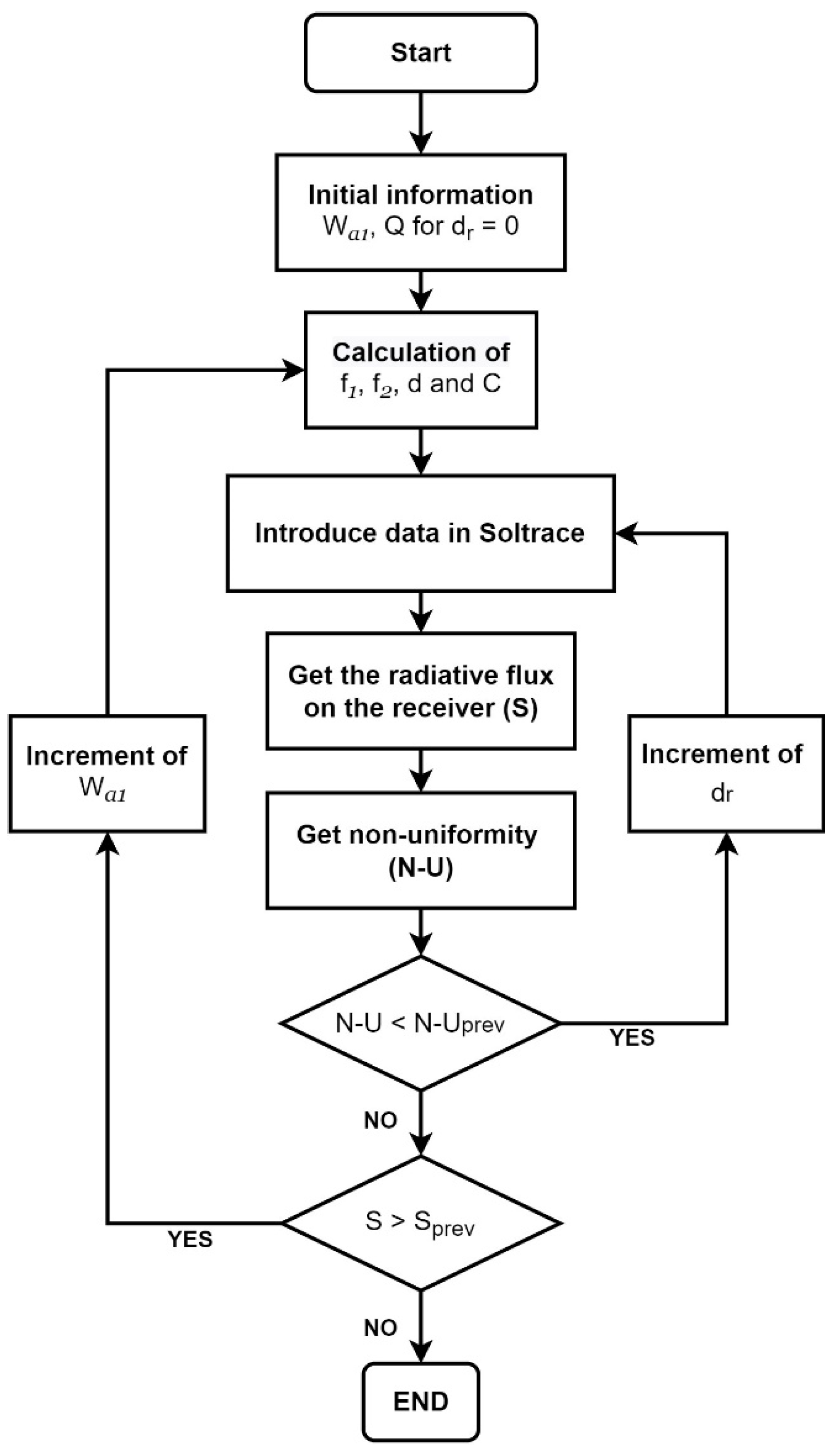
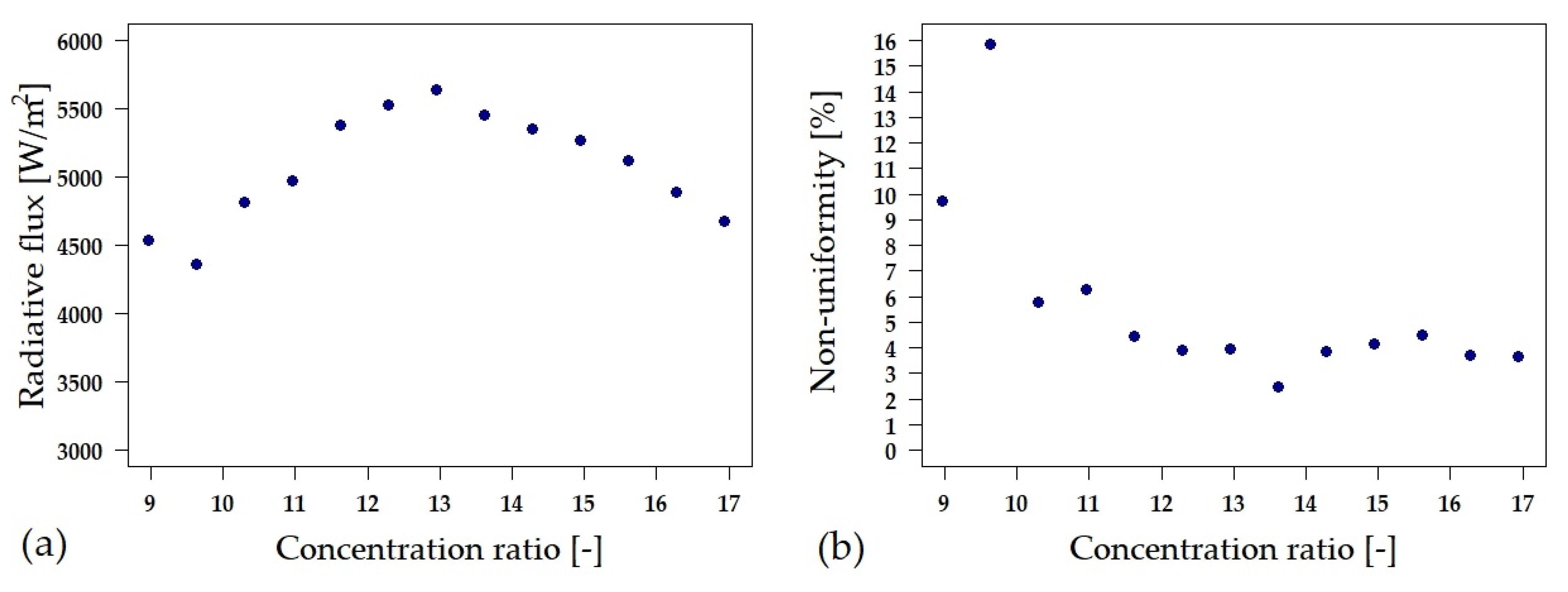
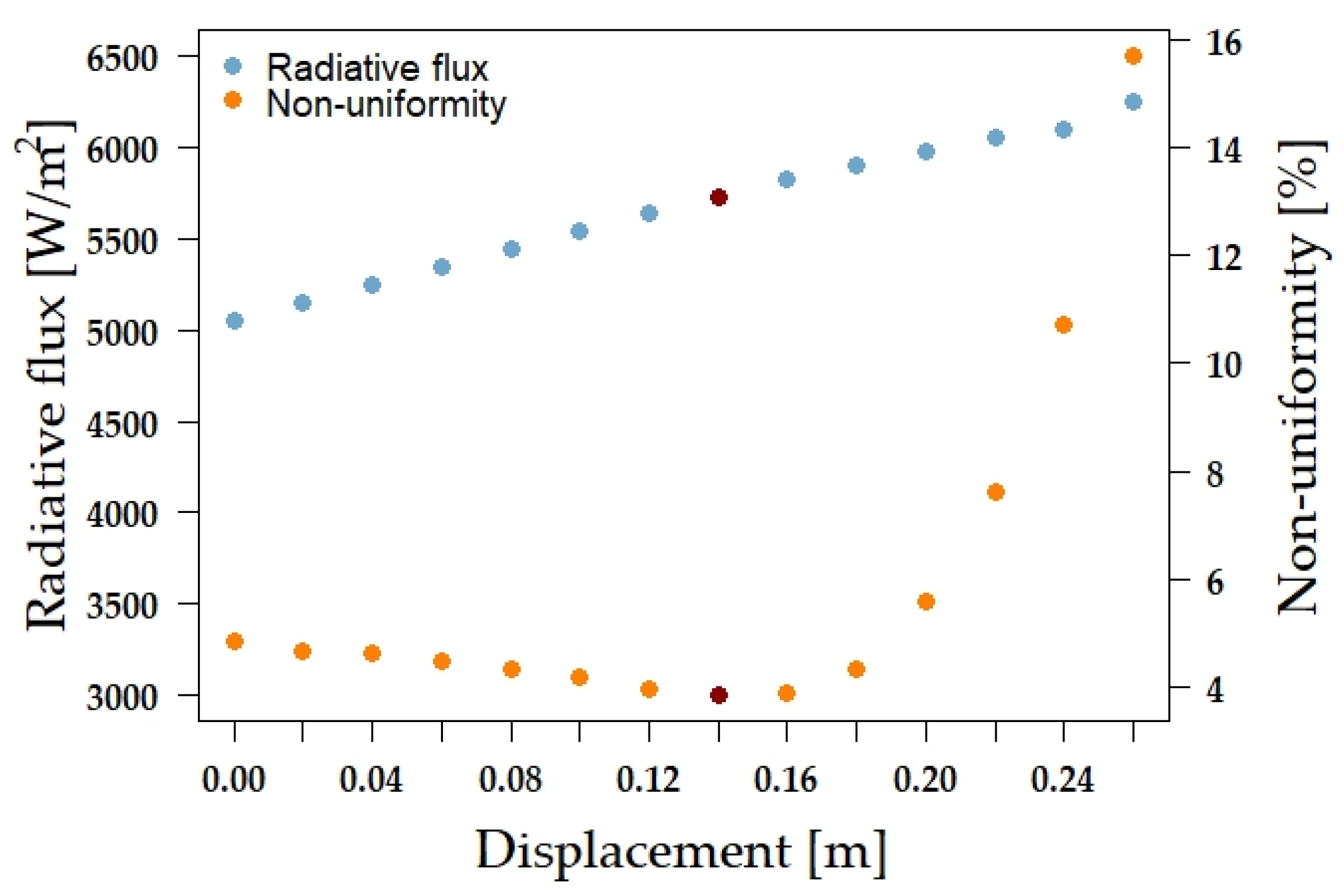
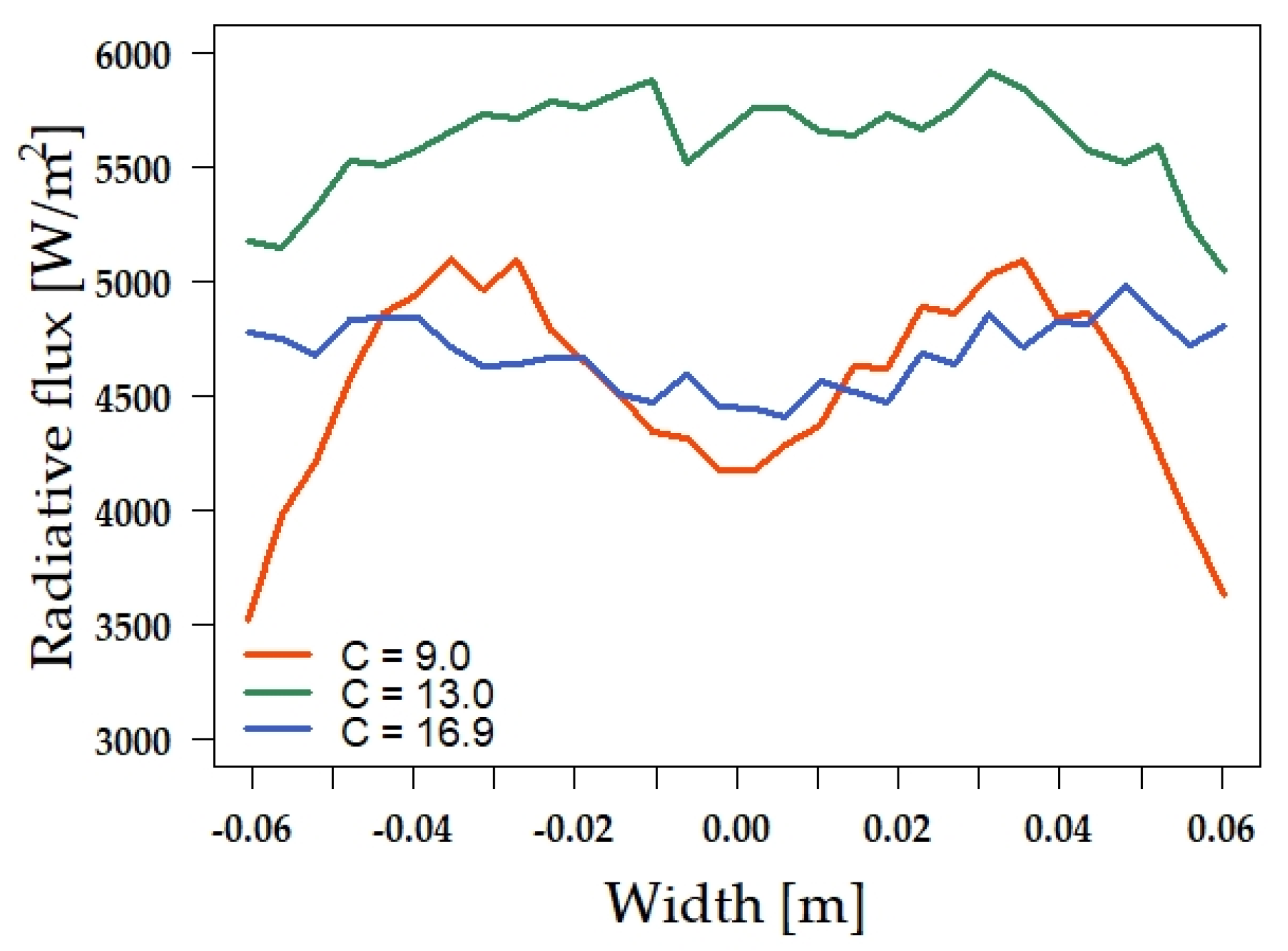
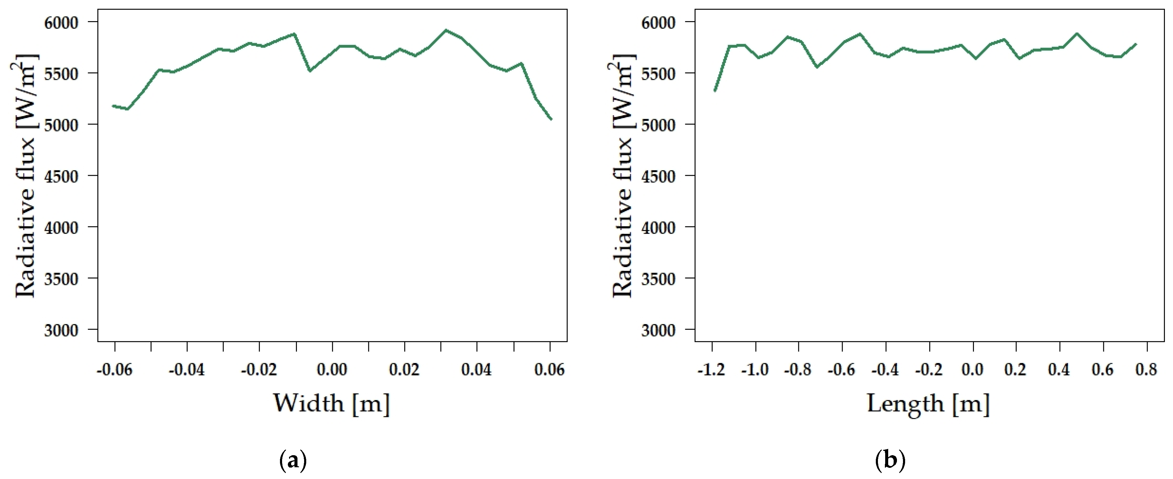
2.2. Optical Performance: Uniformity and Flux Analysis

Optical performance indicates the amount of radiation the receiver is intercepting, in addition to the degree of uniformity of the concentrated flux. Therefore, the solar radiative flux distribution and non-uniformity were considered parameters for calculating the optical performance. The radiative flux parameter allows estimating the energy per area unit that the receiver intercepts as the concentration ratio increases; this implies that the primary parabola’s width and focal length increase. Due to the secondary reflector scattering the solar irradiance, it was deduced that the reflected rays split into a cone, so by reducing the distance between the secondary reflector and the receiver, more energy can be captured.
The flux distribution on the receiver was analyzed by conducting a ray-tracing analysis using SolTrace®, an open-source software developed by the National Renewable Energy Laboratory (NREL, Golden, CO, USA) of the U.S. Department of Energy. This code performs the ray-tracing analysis applying Monte Carlo’s methodology. A Gaussian Sun shape, a slope error of 3.73 mrad [34], and a specular error of 3 mrad [35] were considered. Through the SolTrace software were obtained the absorbed solar radiation and non-uniformity, which are the variables of interest. First, a million rays were traced with a radiative intensity of 1000 W/m2. Therefore, the absorbed solar radiation is the energy that remains in the rays that reach the receiver. Secondly, the SolTrace software generates statistical information of a 2D flux distribution grid, divided into boxes with coordinates (i,j). Finally, the software quantifies the photon number falling in each box and the power-related. Hence, the non-uniformity is calculated as the standard deviation of the radiative flux in the box (i,j) divided by the average radiative flux of the entire grid.
For the case study analyzed, the maximum incidence angle was 44.67°, and the initial solar concentration ratio was 9.0. The concentration ratio was increased to analyze the radiative flux distribution. In total, 13 cases were analyzed.
For each case, the focal length of the primary parabola was adjusted to obtain the maximum radiative flux on the receiver; the secondary parabola width was kept constant and equal to the width of the receiver. As the first approximation, the receiver was established at the vertex of the parabola, that is, dr = 0 m. Then, the geometrical parameters of the primary parabola were calculated. This information was fed into SolTrace software to determine the radiative flux (absorbed solar radiation) and the non-uniformity. After, the receiver was displaced from coordinates (0,0) to (0,dr) to obtain new radiative flux and non-uniformity profiles. This procedure was repeated until a minimum non-uniformity was reached. The last step of the methodology was to determine the concentration ratio, where the highest radiative flux was achieved by incrementing the primary parabola width and repeating the previous steps. This maximum corresponds to a single value of radiative flux, reaching an optimized value of the receiver’s position and optical performance, with a minimum non-uniformity. Figure 3 shows the algorithm for obtaining solar radiative flux and non-uniformity.
In order to determine the focal distances and the solar concentration of each CPV/T geometry, the following relations were used:
f 1 = W a 1 4 tan ( ϕ / 2 ) ,
C = W a 1 W a 2 ,
f 2 = f 1 C ,
d = f 1 f 2 .

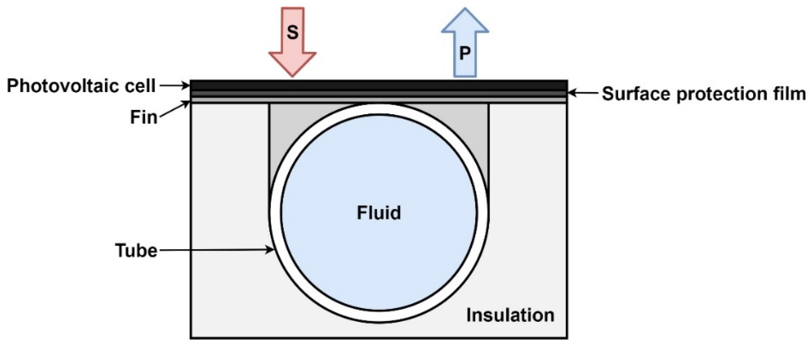
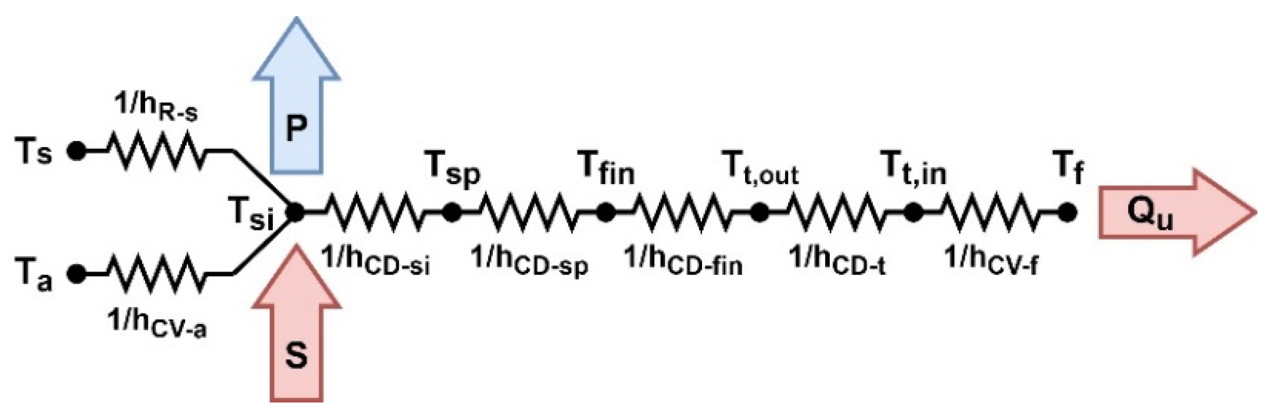
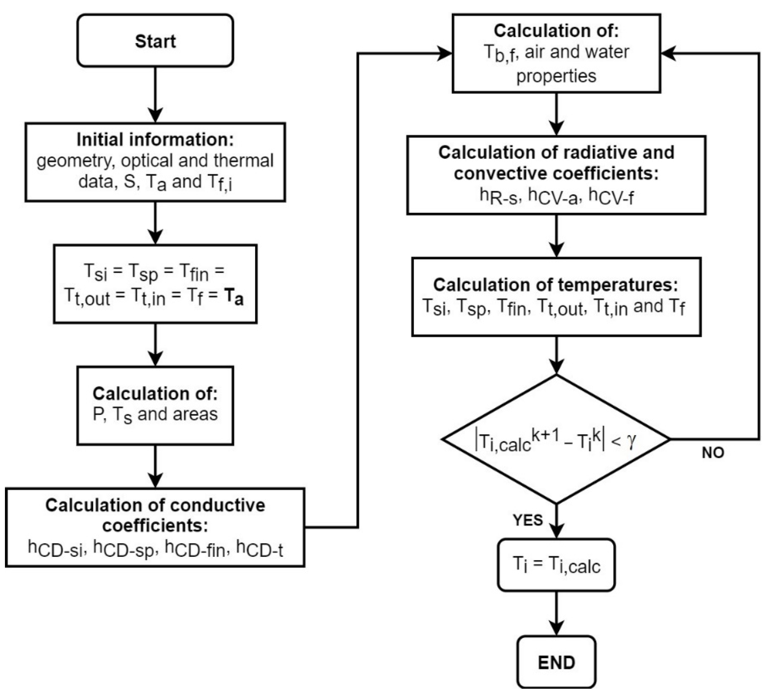
2.3. Thermal Analysis

The heat transfer model in the CPV/T receiver of the proposed optical design was developed to determine the photovoltaic and thermal efficiencies and the photovoltaic cell and fluid temperatures. Additionally, these results were compared in a scenario where the CPV/T receiver was not cooled, that is, if it had no means of extracting heat.
The temperature of a conventional photovoltaic panel (without cooling) is:
T s i = T a + G ( T N O T r e f G r e f ) ,
T N O is obtained from the specification sheet of the PV model, with values between 43 °C and 49 °C.
In the hybrid concentrated photovoltaic solar collector proposed, the photovoltaic panel is located in the receiver position, which is cooled with an arrangement of fin and tube that circulates a fluid to produce both electrical and thermal energy. Figure 4 shows the receiver of the CPV/T collector, where thermal analysis was performed. Figure 5 shows the corresponding thermal network in terms of conduction, convection, and radiation resistances.
The energy balances in the photovoltaic cell, bonding material, thermal fin, outer and inner tube wall, and fluid are, respectively:
S h R s A p v ( T s i T s ) h C V a A p v ( T s i T a ) P h C D s i A p v ( T s i T s p ) = 0 ,
h C D s i A p v ( T s i T s p ) h C D s p A p v ( T s p T f i n ) = 0 ,
h C D s p A p v ( T s p T f i n ) h C D f i n A s t t , o u t ( T f i n T t , o u t ) = 0 ,
h C D f i n A s t t , o u t ( T f i n T t , o u t ) h C D t A t , i n ( T t , o u t T t , i n ) = 0 ,
h C D t A t , i n ( T t , o u t T t , i n ) h C V f A t , i n ( T t , i n T f , b ) = 0 ,
h C V f A t , i n ( T t , i n T f , b ) m ˙ C p ( T f T f , i ) = 0 .
where:
A p v = W p v L p v ,   A s t t , o u t = D t , o u t L t ,   A t , i n = π D t , i n L t .
Appendix A shows the equations used to evaluate the heat transfer coefficients. The value of the absorbed solar radiation, S, is a result of the optical analysis. The optical efficiency is:
η o p = S G .
The electric power produced by the photovoltaic panel is a function of its electric efficiency, which depends on its temperature as [36]:
η e l = η r e f [ 1 β r e f ( T s i T r e f ) ] ,
P = η e l S .
The electric efficiency of the concentrating module is:
η e l , c o n c = P G .
The heat transfer model was resolved iteratively. MatLab program version R2019b of MathWorks® (Torrance, CA, USA) was used to develop the algorithm of this numerical analysis. Figure 6 shows the flowchart of the numerical solution, where the convergence criteria are:
[ | T s i k + 1 T s i k | , | T s p k + 1 T s p k | , | T f i n k + 1 T f i n k | , | T t , o u t k + 1 T t , o u t k | , | T t , i n k + 1 T t , i n k | , | T f k + 1 T f k | ] γ ,
with γ = 1 × 10 3 .
Finally, the thermal efficiency of the CPV/T collector is:
η t h = m ˙ C p ( T f T f , i ) G .
Table 2 shows the thickness and thermal conductivities of the selected materials in the CPV/T receptor. For thermal analysis, a silicon emissivity of 0.75 was considered [37], as well as an inlet fluid temperature of 293.15 K, a wind velocity of 2 m/s, and a mass flow rate of 0.0324 kg/s.
In order to develop thermal analysis, a third-generation monocrystalline silicon cell was selected, with an efficiency between 22% and 24%, higher than conventional silicon cells. Its main characteristics are enlisted in Table 3.

3. Results and Discussion

As Figure 7a reveals, once the optical design methodology was carried out (See Sec: Methodology), the concentration radio with the highest radiative flux achieved was C = 13.0. Meanwhile, Figure 7b shows the radiative flux non-uniformity for the 13 different concentration ratios analyzed. It is clear from both figures that the case with the lowest radiative flux also has the highest non-uniformity (C = 9.6). However, there is no clear relationship between both variables for the other cases. Moreover, it can be seen that the non-uniformity for the concentration ratio C = 13.0 was less than 4%. The cases beyond C = 13.0 are shown only as an example of how, after reaching the maximum, the radiative flux decreases with the concentration ratio; it is observed that the proposed methodology provides valuable insight for when the configuration where the concentration has the highest radiative flux, and better uniformity is found.
To visualize the non-uniformity improvement, Table 4 shows the non-uniformity and average radiative flux variation when the receiver’s displacement increases until minimum uniformity is reached. The analysis was performed for the best-case scenario, C = 13.0, with f1 = 0.445 m and f2 = 0.032 m.
Additionally, Figure 8 shows the relation of radiative flux and non-uniformity with the displacement of the receiver, also, for the best-case scenario (C = 13.0), including data beyond the optimum displacement. The minimum non-uniformity value (inflection point) corresponds to the optimal receiver displacement (dr = 0.14 m) for maximum radiative flux with the best distribution. As can be seen, the radiative flux always increases with increasing receptor displacement; however, the non-uniformity decreases marginally as the displacement grows, but once it reaches its minimum value, its behavior becomes exponential.
Figure 9 presents more information about how is the non-uniformity distribution. It shows the transverse radiative flux distributions for three different concentration ratios: the initial value (C = 9.0), the one with the highest radiative flux (C = 13.0), and a case with a high concentration ratio (C = 16.9). As can be appreciated, a clear distribution is found in the initial value’s case, which has a high non-uniformity, with lower radiative fluxes at the receiver edges and its vertex. In contrast, the case with the highest concentration shows the lowest radiative flux at the vertex while it grows at the edges. Finally, the case with the highest radiative flux has an intermediate distribution of both previous cases.
Concluding the analysis of the optical results and returning to the selected case as the best, Figure 10 shows the radiative flux distributions over the cross-section (width) and longitudinal section (length) for the concentration ratio of 13.0 and displacement of 0.14 m. It can be observed in an average flux of 5607.02 W/m2 ± 217.19 W/m2 for cross-section and an average flux of 5718.84 W/m2 ± 103.98 W/m2 for the longitudinal section.
According to the ray-tracing analysis, the radiative flux distribution in the cells is uniform, and therefore there is no hotspot formation, as seen in Figure 10. The configuration of C = 13.0 and minimum non-uniformity for this geometry ensure that it has the best optical performance for the requirements of the solar cells, minimizing the hot spots and ensuring a safe radiative flux (less than seven Suns) for the selected photovoltaic cells. Furthermore, the proposed methodology is a helpful tool for optimizing the design of linear parabolic Cassegrain-type CPV/T solar collectors because it allows through a parametric analysis to obtain an optimized design configuration by varying Wa and dr, solely.
Finally, thermal analysis was performed on this optical configuration, with solar radiation incident on the collector aperture area of 3951.34 W, of which 1408.92 W reached the receiver. Thus, both radiation values were obtained from the optical analysis. Table 5 shows the main thermal and electrical results.
As can be seen, the proposed solar concentrator allows reaching a working fluid temperature increase of 6.68 K in a single step of 2 m, with electrical and total efficiencies of 7.28% and 22.91%, respectively. Moreover, this design allows obtaining a quasi-uniform radiation distribution and higher temperatures in the working fluid using 26.67% (16 cells) of the cells with a conventional photovoltaic module of 270 W (60 cells), with an overall efficiency of 30.2%. Moreover, it is relevant to note that if a linear Cassegrain-type CPV solar collector was not cooled, the silicon cell temperature and electrical efficiency would decay to values of 405.9 K and 5.9%, respectively.
Although the temperature rise of the photovoltaic cell is almost 55 K, these values are encouraging since they are slightly lower than those reported in other works [30], for solar concentration levels below 10 (cell temperature between 293.15 K and 358.15 K with electrical efficiencies between 10% and 18%).
On the other hand, even though the electrical and thermal efficiencies are low for this particular case, the main objective of this work was to develop a methodology to determine a better design to minimize the non-uniformity of radiative distribution over the receptor. Thus, the proposed parametric methodology allows optimizing the global efficiency of a parabolic Cassegrain CPV/T by maximizing concentrated solar flux and minimizing non-uniformity on the receiver. Furthermore, the secondary parabola has the same characteristics as the primary one in the proposed optical design. Therefore, this consideration makes it unnecessary to create two complex geometries, keeping manufacture simple and facilitating its large-scale implementation.

4. Conclusions

In this study, a simplified parametric methodology was developed for the optical design of a Cassegrain type parabolic CFV/T collector, with the primary purpose of minimizing the radiative flux’ non-uniformity over the photovoltaic cells on the receiver. In order to achieve it, the receptor is displaced from the concentrator edge until an optimal displacement distance. Additionally, a model was developed to evaluate the thermal performance of the solar collector.
The developed approach was used to examine a case study with a receiver width of 0.125 m, an 80° rim angle, and a commercial silicon photovoltaic cell that supports up to 7000 W/m2. After applying the methodology, a hybrid solar collector with a concentration ratio of 13.0 and a receiver displacement of 0.14 m was obtained as the best-case scenario. This optical design guarantees an average radiative flux on the PV cells of 5728 W/m2 and a non-uniformity of less than 4%, considering an optical error close to real systems. Simultaneously, this design makes it possible to maintain the cell at a temperature of 353 K and obtain a fluid temperature increase of 6.68 K, with a total efficiency of 30.2%.
From the results, the following conclusions can be deduced:
The receiver displacement has a positive effect on both radiative flux and non-uniformity. The radiative flux that reaches the receiver increases, while the non-uniformity is dependent since it decreases until a minimum. If the displacement is increased beyond this minimum, it will impact negatively since the non-uniformity will increase exponentially. Therefore, special care must be taken as a large displacement can negatively affect it.
The results of this study indicate that there is no clear relationship between the optimized non-uniformity and the higher radiative flux with the solar concentration.
For geometries with a specific rim angle, the methodology allows determining the better concentration ratio to achieve the highest radiative flux over the receiver and guarantee a minimized non-uniformity, only modifying the primary concentrator width and receiver displacement. However, this methodology does not consider the optical efficiency as a parameter to optimize; this topic is postponed to future work.

Author Contributions

Conceptualization and validation, E.V.-R., N.O.-A., and M.I.P.-C.; methodology and formal analysis, E.V.-R., and N.O.-A.; software and resources, E.V.-R., and O.J.G.-O.; investigation, E.V.-R., N.O.-A., and O.J.G.-O.; data curation, E.V.-R.; writing—original draft preparation, E.V.-R., N.O.-A., and N.A.R.-M.; writing—review and editing, N.O.-A., M.I.P.-C., and N.A.R.-M.; visualization, supervision and project administration, N.O.-A. All authors have read and agreed to the published version of the manuscript.

Funding

This research received no external funding.

Institutional Review Board Statement

Not applicable.

Informed Consent Statement

Not applicable.

Data Availability Statement

The data presented in this study are available on request from the corresponding author.

Acknowledgments

The authors are grateful to CONACYT for financial support by means of the scholarship 701505.

Conflicts of Interest

The authors declare no conflict of interest.

Nomenclature

A Area (m2)
C Solar concentration (dimensionless)
C p Specific heat (J/(kg K))
d Distance between the optical elements (m)
d r Displacement of the receiver (m)
D Diameter (m)
e Thickness (m)
f Friction factor (dimensionless)
f 1 Focal length of the primary concentrator (m)
f 2 Focal length of the secondary reflector (m)
G Irradiance over the primary aperture (W)
h Heat transfer coefficient (W/(m2 K))
k Thermal conductivity (W/(m K))
L Length (m)
m ˙ Mass flow rate (m/s)
N u Nusselt number (dimensionless)
P Power (W)
P r Prandtl number (dimensionless)
Q Energy per unit time (W)
r r Mirror radius (m)
R e Reynolds number (dimensionless)
S Absorbed solar radiation (W)
T Temperature (K)
V Velocity (m/s)
W Width (m)
W a 1 Parabola’s width of the primary concentrator (m)
W a 1 Parabola’s width of the secondary reflector (m)
Greek symbols
β Temperature coefficient (1/K)
γ Convergence criteria (K)
ε Emissivity (dimensionless)
φ Rim angle (°)
η Efficiency (dimensionless)
ρ Density (kg/m3)
μ Dynamic viscosity (kg/(m s))
σ Stephan-Boltzman constant (5.67 × 10⁻⁸ W/(m2 K4))
Subscript
a Ambient
a 1 Primary concentrator aperture
a 2 Secondary reflector aperture
a i r Air
a p Aperture
b Bulk
C D Conductive
c o n c Concentrated
C V Convective
e l Electrical
f Fluid
f i n Fin
i Inlet
i n Inner
k Iteration number
l a m Laminar
N O Nominal operation
o p Optical
o u t Outer
p r e v Previous value
p v Photovoltaic cell
R Radiative
r e f Reference
s Sky
s i Silicon
s p Surface protection film
T Temperature
t Tube
t r a n s Transient
t u r b Turbulent
u Useful
w Water

Appendix A. Evaluation of the Heat Transfer Coefficients

The only radiation heat transfer coefficient involves in the thermal model is between the photovoltaic cell and the sky:
h R s = σ ε s i ( T s i + T s ) ( T s i 2 + T s 2 ) ,
where T s is calculated as [40]:
T s = 0.05532 T a 1.5 .
The convective heat transfer coefficient between the photovoltaic cell and the ambient is [41]:
N u a i r , l a m = 0.664 R e P r 3 ,
for turbulent flow, with 5 × 10 5 < R e < 10 7 and 0.5 < P r < 2000 :
N u a i r , t u r b = 0.037 R e 0.8 P r 1 + 2.443 R e 0.1 ( P r 2 / 3 1 ) ,
and, in the transition zone, with 5 × 10 3 < R e < 5 × 10 5 and 0.5 < P r < 2000 :
N u a i r , t r a n s = ( T a T s i ) 0.12 N u s i , l a m 2 + N u s i , t u r b 2 ,
where the Reynolds number is:
R e = ρ a i r V a i r L p v μ a i r .
Appropriated correlations were developed to calculate the air properties in the range from 0 °C to 100 °C.
The fluid convective heat transfer coefficient was modeled as internal forced convection in a tube with constant heat flux. For fully developed turbulent flow [42]:
N u = 0.125 f R e P r 1 / 3 ,
f = ( 0.790 ln R e 1.64 ) 2 ,           3000 < R e < 5 × 10 6 ,
where the Reynolds number is calculated as:
R e = ρ w V w D t , i n μ w .
The water properties were evaluated at the bulk fluid temperature in saturation conditions:
T f , b = T f + T f , i 2 .
Finally, the convective coefficients are:
h C D s i = k s i e s i ,           h C D s p = k s p e s p ,         h C D f i n = k f i n e f i n ,         h C D t = k t e t .

References

  1. IEA—International Energy Agency World: Energy Consumption, Electricity Consumption. Available online: https://www.iea.org/data-and-statistics/data-browser?country=WORLD&fuel=Energyconsumption&indicator=TotElecCons (accessed on 19 October 2021).
  2. Bouckaert, S.; Pales, A.; Fernandez, M.; Christophe, R.; Uwe, W.; Brent, V.; Laszlo D’, A.; Davide, S.T. IEA—International Energy Agency Net Zero by 2050. A Roadmap for the Global Energy Sector 2021; TRID: Paris, France, 2021; p. 222. [Google Scholar]
  3. Laura, C.; Tim, G. IEA—International Energy Agency World Energy Outlook 2021; IEA: Paris, France, 2021; p. 386. [Google Scholar]
  4. Besheer, A.H.; Smyth, M.; Zacharopoulos, A.; Mondol, J.; Pugsley, A. Review on recent approaches for hybrid PV/T solar technology. Int. J. Energy Res. 2016, 40, 2038–2053. [Google Scholar] [CrossRef]
  5. Yazdanifard, F.; Ameri, M. Exergetic advancement of photovoltaic/thermal systems (PV/T): A review. Renew. Sustain. Energy Rev. 2018, 97, 529–553. [Google Scholar] [CrossRef]
  6. Ju, X.; Xu, C.; Han, X.; Du, X.; Wei, G.; Yang, Y. A review of the concentrated photovoltaic/thermal (CPVT) hybrid solar systems based on the spectral beam splitting technology. Appl. Energy 2017, 187, 534–563. [Google Scholar] [CrossRef]
  7. Gomaa, M.R.; Mustafa, R.J.; Rezk, H.; Al-Dhaifallah, M.; Al-Salaymeh, A. Sizing methodology of a multi-mirror solar concentrated hybrid PV/thermal system. Energies 2018, 11, 3276. [Google Scholar] [CrossRef] [Green Version]
  8. Yin, E.; Li, Q.; Xuan, Y. A novel optimal design method for concentration spectrum splitting photovoltaic–thermoelectric hybrid system. Energy 2018, 163, 519–532. [Google Scholar] [CrossRef]
  9. Gomaa, M.R.; Al-Dhaifallah, M.; Alahmer, A.; Rezk, H. Design, modeling, and experimental investigation of activewater cooling concentrating photovoltaic system. Sustainability 2020, 12, 5392. [Google Scholar] [CrossRef]
  10. Yang, F.; Wang, H.; Zhang, X.; Tian, W.; Hua, Y.; Dong, T. Design and experimental study of a cost-effective low concentrating photovoltaic/thermal system. Sol. Energy 2018, 160, 289–296. [Google Scholar] [CrossRef]
  11. Othman, Y.; Hussain, F. Designs of various hybrid photovoltaic-thermal (PV/T) solar collectors. In Photovoltaics for Sustainable Electricity and Buildings; Springer International Publishing: Cham, Switzerland, 2017; pp. 1–186. [Google Scholar]
  12. Guo, J.; Zheng, L. Numerically study on a new hybrid photovoltaic thermal (PVT) collectors with natural circulation. Appl. Sol. Energy (English Transl. Geliotekhnika) 2017, 53, 316–321. [Google Scholar] [CrossRef]
  13. Haloui, H.; Touafek, K.; Zaabat, M.; El Hocine, H.B.C.; Khelifa, A. Modelling of a hybrid photovoltaic thermal collector based on CdTe. Appl. Sol. Energy (English Transl. Geliotekhnika) 2016, 52, 27–31. [Google Scholar] [CrossRef]
  14. Othman, Y.; Hussain, F.; Sopian, K.; Yatim Baharuddin, R.H. Design of various hybrid single-pass photovoltaic–thermal (PV/T) solar collector. In Renewable Energy in the Service of Mankind Vol II; Springer International Publishing: Cham, Switzerland, 2016. [Google Scholar]
  15. Wang, G.; Yao, Y.; Lin, J.; Chen, Z.; Hu, P. Design and thermodynamic analysis of a novel solar CPV and thermal combined system utilizing spectral beam splitter. Renew. Energy 2020, 155, 1091–1102. [Google Scholar] [CrossRef]
  16. Ben Youssef, W.; Maatallah, T.; Menezo, C.; Ben Nasrallah, S. Modeling and optimization of a solar system based on concentrating photovoltaic/thermal collector. Sol. Energy 2018, 170, 301–313. [Google Scholar] [CrossRef]
  17. Aste, N.; Del Pero, C.; Leonforte, F.; Manfren, M. Performance monitoring and modeling of an uncovered photovoltaic-thermal (PVT) water collector. Sol. Energy 2016, 135, 551–568. [Google Scholar] [CrossRef]
  18. Khelifa, A.; Touafek, K.; Ben Moussa, H. Approach for the modelling of hybrid photovoltaic-thermal solar collector. IET Renew. Power Gener. 2015, 9, 207–217. [Google Scholar] [CrossRef]
  19. Vardanyan, R.R.; Dallakyan, V.K.; Travajyan, M.G. Temperature dependent performance of solar photovoltaic and thermal hybrid systems. J. Contemp. Phys. 2020, 55, 339–344. [Google Scholar] [CrossRef]
  20. Han, X.; Xu, C.; Pan, X.Y.; Ju, X.; Du, X.Z. Dynamic analysis of a concentrating photovoltaic/concentrating solar power (CPV/CSP) hybrid system. Sci. China Technol. Sci. 2019, 62, 1987–1998. [Google Scholar] [CrossRef]
  21. Afzali Gorouh, H.; Salmanzadeh, M.; Nasseriyan, P.; Hayati, A.; Cabral, D.; Gomes, J.; Karlsson, B. Thermal modelling and experimental evaluation of a novel concentrating photovoltaic thermal collector (CPVT) with parabolic concentrator. Renew. Energy 2022, 181, 535–553. [Google Scholar] [CrossRef]
  22. Herrando, M.; Ramos, A.; Zabalza, I.; Markides, C.N. A comprehensive assessment of alternative absorber-exchanger designs for hybrid PVT-water collectors. Appl. Energy 2019, 235, 1583–1602. [Google Scholar] [CrossRef] [Green Version]
  23. Nasseriyan, P.; Gorouh, H.A.; Gomes, J.; Cabral, D.; Salmanzadeh, M.; Lehmann, T.; Hayati, A. Numerical and experimental study of an asymmetric CPC-PVT solar collector. Energies 2020, 13, 1669. [Google Scholar] [CrossRef] [Green Version]
  24. Cabral, D.; Gomes, J.; Hayati, A.; Karlsson, B. Experimental investigation of a CPVT collector coupled with a wedge PVT receiver. Sol. Energy 2021, 215, 335–345. [Google Scholar] [CrossRef]
  25. Wang, G.; Yao, Y.; Chen, Z.; Hu, P. Thermodynamic and optical analyses of a hybrid solar CPV/T system with high solar concentrating uniformity based on spectral beam splitting technology. Energy 2019, 166, 256–266. [Google Scholar] [CrossRef]
  26. Herez, A.; El Hage, H.; Lemenand, T.; Ramadan, M.; Khaled, M. Review on photovoltaic/thermal hybrid solar collectors: Classifications, applications and new systems. Sol. Energy 2020, 207, 1321–1347. [Google Scholar] [CrossRef]
  27. Joshi, S.S.; Dhoble, A.S. Photovoltaic -Thermal systems (PVT): Technology review and future trends. Renew. Sustain. Energy Rev. 2018, 92, 848–882. [Google Scholar] [CrossRef]
  28. Sharaf, O.Z.; Orhan, M.F. Concentrated photovoltaic thermal (CPVT) solar collector systems: Part I—Fundamentals, design considerations and current technologies. Renew. Sustain. Energy Rev. 2015, 50, 1500–1565. [Google Scholar] [CrossRef]
  29. Sharaf, O.Z.; Orhan, M.F. Concentrated photovoltaic thermal (CPVT) solar collector systems: Part II—Implemented systems, performance assessment, and future directions. Renew. Sustain. Energy Rev. 2015, 50, 1566–1633. [Google Scholar] [CrossRef]
  30. Alzahrani, M.; Shanks, K.; Mallick, T.K. Advances and limitations of increasing solar irradiance for concentrating photovoltaics thermal system. Renew. Sustain. Energy Rev. 2021, 138, 110517. [Google Scholar] [CrossRef]
  31. Mauk, C.E.; Prengle, H.W.; Sun, E.C.H. Optical and thermal analysis of a cassegrainian solar concentrator. Sol. Energy 1979, 23, 157–167. [Google Scholar] [CrossRef]
  32. Wu, S.; Tang, R.; Wang, C. Numerical calculation of the intercept factor for parabolic trough solar collector with secondary mirror. Energy 2021, 233, 121175. [Google Scholar] [CrossRef]
  33. Granata, J.E.; Sorensen, N.R.; Riley, D.; Judkins, Z.; Olsen, S. Design for reliability: A low concentration PV case study. Conf. Rec. IEEE Photovolt. Spec. Conf. 2012, 1739–1743. [Google Scholar]
  34. Venegas-Reyes, E.; Jaramillo, O.A.; Castrejón-García, R.; Aguilar, J.O.; Sosa-Montemayor, F. Design, construction, and testing of a parabolic trough solar concentrator for hot water and low enthalpy steam generation. J. Renew. Sustain. Energy 2012, 4, 053103. [Google Scholar] [CrossRef]
  35. Rabl, A. Active Solar Collectors and Their Applications, 1st ed.; Oxford University Press Inc.: New York, NY, USA, 1985. [Google Scholar]
  36. Kalogirou, S.A. Solar Energy Engineering: Processes and Systems, 2nd ed.; Academic Press: Cambridge, ME, USA, 2014. [Google Scholar]
  37. Riverola, A.; Mellor, A.; Alonso Alvarez, D.; Ferre Llin, L.; Guarracino, I.; Markides, C.N.; Paul, D.J.; Chemisana, D.; Ekins-Daukes, N. Mid-infrared emissivity of crystalline silicon solar cells. Sol. Energy Mater. Sol. Cells 2018, 174, 607–615. [Google Scholar] [CrossRef] [Green Version]
  38. Hammami, M.; Torretti, S.; Grimaccia, F.; Grandi, G. Thermal and performance analysis of a photovoltaic module with an integrated energy storage system. Appl. Sci. 2017, 7, 1107. [Google Scholar] [CrossRef] [Green Version]
  39. SunPower Corporation MAXEON TM. GEN III SOLAR CELLS Electrical Characteristics of a Typical Maxeon Gen III Cell; Sunpower: San Jose, CA, USA, 2017. [Google Scholar]
  40. Swinbank, W.C. Long-wave radiation from clear skies. Q. J. R. Meteorol. Soc. 1963, 89, 339–348. [Google Scholar] [CrossRef]
  41. Hewitt, G.F. Heat Exchanger Design Handbook. Volume 2: Fluid Mechanics and Heat Transfer. In; Hemisphere Publishing Corporation: San Francisco, CA, USA, 1983. [Google Scholar]
  42. Engel, Y.A. Heat Transfer: A Practical Approach, 2nd ed.; Mcgraw-Hill: Blacklick, OH, USA, 2002. [Google Scholar]
Figure 1. Geometry of the linear Cassegrain-type thermal photovoltaic concentrator.
Energies 14 08155 g001
Figure 2. Linear Cassegrain-type CPV/T solar collector with displaced receiver.
Energies 14 08155 g002
Figure 3. Flowchart of the radiative flux and the non-uniformity calculation.
Energies 14 08155 g003
Figure 4. The CPV/T receiver.
Energies 14 08155 g004
Figure 5. Thermal network for the receiver of the CPV/T collector.
Energies 14 08155 g005
Figure 6. Flowchart of the heat transfer model.
Energies 14 08155 g006
Figure 7. (a) Average radiative flux at the receiver; (b) non-uniformity for 13 different concentration ratios.
Energies 14 08155 g007
Figure 8. Relation between the radiative flux and the non-uniformity for different receiver’s displacement.
Energies 14 08155 g008
Figure 9. Cross-section radiative flux distribution for four different concentration ratios.
Energies 14 08155 g009
Figure 10. Radiative flux distribution for the concentration ratio of 13.0 and displacement of 0.14 m at: (a) cross-section; (b) longitudinal section of the receiver.
Energies 14 08155 g010
Table 1. Initial geometrical and optical parameters of the linear Cassegrain-type thermal photovoltaic concentrator.
ComponentLength (m)Width (m)Focal Length (m)Coordinates
PPC2.441.1210.297(0,0)
SPR2.440.1250.024(0,0.027)
Receiver2.000.125---(0,dr)
Table 2. Properties of the selected materials in the CPV/T receptor.
ComponentMaterialThickness (mm)Thermal Conductivity (W/(m K))
Photovoltaic cellSilicon1.5150 1
Surface protection filmTedlar1.00.35 1
FinCooper4.6401
TubeCooper7.1401
1 Data from Hammami et al., 2017 [38].
Table 3. Characteristics of the photovoltaic cells [39].
ParameterValue
TechnologyMonocrystalline silicon
Dimensions (mm)125 × 125
Thickness (μm)150 ± 30
Nominal operation temperature (°C)45
Reference temperature (°C)25
Reference irradiance (W/m2)1000
Efficiency at standard test conditions (%)24.3
Temperature power coefficient (%/°C)0.29
Maximum solar concentration supported (W/m2)7000
Table 4. Non-uniformity and average radiative flux at the receiver by incrementing its displacement for the best-case scenario: C = 13.0, Wa1 = 1.62 m, f1 = 0.445 m, f2 = 0.032 m.
Displacement (m)Non-Uniformity (%)Radiative Flux (W/m2)
0.004.855046.8
0.024.685149.2
0.044.625246.9
0.064.505342.9
0.084.325441.1
0.104.175538.1
0.123.985635.7
0.143.845728.2
Table 5. Thermal and electrical production of the linear Cassegrain-type CPV/T solar collector, with Tf,I = 293.15 K, Ta = 288.15 K, Vair = 2 m/s, m ˙ = 0.0324 kg/s, G = 3952.3 W and S = 1408.9 W.
ParameterResult
Silicon cell temperature (K)353.0
Outlet fluid temperature (K)299.8
Produced power (W)287.9
Fluid extracted heat (W)905.9
Optical efficiency (%)35.7
Electrical efficiency (%)7.3
Thermal efficiency (%)22.9
Overall efficiency (%)30.2
Publisher’s Note: MDPI stays neutral with regard to jurisdictional claims in published maps and institutional affiliations.

