1. Introduction
Microgrids are being used mainly to increase resilience and reliability of electrical grids, to integrate the addition of distributed renewable energy sources like wind, solar photovoltaic (PV) or micro-hydropower generation, to provide electricity in isolated areas not served by centralized electrical networks, and to reduce greenhouse gases emissions. According to [
1], a MG is a group of interconnected loads and distributed energy resources within clearly defined electrical boundaries that acts as a single controllable entity with respect to the grid. A microgrid can connect and disconnect from the grid to enable it to operate in both grid-connected or island mode.
More than 130 million people around the world are served by MGs and a 67 percent of these are by autonomous micro-hydro power plants (AMHPP) [
2]. Electricity is a key resource for gathering basic modern human needs and MGs may be the best way to deliver electricity to rural areas. The future development of electricity and its universal availability is an extremely important issue and depends on the possibility of providing access to it for all those who demand it in constantly growing economies, assuming that this energy comes from sources that are reliable, safe and environmentally friendly [
3]. Since most MGs generating sources lack the inertia used by large synchronous generators, an efficient primary frequency control is needed to reduce the impact of imbalances of electricity generation and demand, especially in AMHPP. Micro-hydropower is one of the most cost-effective renewable energy technologies to be considered for rural electrification in developing countries. Although others renewable sources of energy that also are not very expensive can be considered (e.g., wind, solar, biomass, among others), a characteristic of AMHPP is that they are in most cases “run-of-river” with no dam or little water storage [
4].
When AMHPP works isolated from centralized electrical grid and as a unique source of energy it is said to operate autonomously [
5,
6]. They require a good control system to keep frequency and voltage outputs constant in spite of changing user loads [
5,
7]. Frequency stability is the most critical issue in isolated power systems due to their low rotational inertia [
8,
9]. Hence, maintaining the grid frequency within a certain range is indeed a challenge [
10,
11].
Classic speed governor is widely used in hydropower control. However, due to the less dynamic response of AMHPP and relatively high costs, the speed governors are less preferred in AMHPP [
12]. In the particular case of Cuba, conventional speed governor is not used for Cuban AMHPP due to prohibitively high cost according to [
13]; therefore, frequency is controlled by resistive load [
14] called dump load. On the other hand, dump load control is proved to be cost effective only when there is a hot water requirement [
15] because it dumped a lot of electricity and water. Therefore, the reduction of a dump load value is needed as much as possible [
12] making the use of water more efficient.
Depending on different site conditions, such as flow rate and gross head, and on the selected generator rated frequency (50 or 60 Hz), some hydraulic turbine types with different operating range and efficiency characteristics are available. They can be divided according to the operational principle into impulse and reaction hydraulic turbines.
Cuba has 107 AMHPP in operation, a 95% of them operate with impulse Pelton turbines. Only six AMHPP have a dump load regulation mechanism which implies inefficient uses of water and poor frequency control, according to legal norms (Law 1287/1975) and techniques NC62-04 [
16].
An alternative to conventional speed governors, is to use DC servomotor [
17] for nozzle control in Pelton turbine. Besides, knowing a demand load pattern is possible to reduce a dump load size [
18]. A combination of a reduced amount of dump load with flow control by adjusting a nozzle setting in Pelton turbines could improve overall energy efficiency from the point of view of water uses. It guarantees frequency control in nominal limits giving better dynamical response than flow control alone at lower cost.
As temporal response of flow control is precise but slower, a user load demands can be compensated rapidly by a reduced dump load. Next, slowly, it must be adjusted linearly the Pelton nozzle setting in accordance to the demanded load magnitude. A well-designed combined flow-dump load control can guarantee a required temporal response. Proportional Integral Derivative (PID) controllers has been widely used in hydropower frequency control [
19,
20,
21,
22,
23]. About 95% of the control loops in industry are PID controllers and fundamentally, most of them PI [
24]. They are also common, making them easy to design and implement this in microcontroller application.
The objective of this research is to propose a way to make more efficient use of the hydro energy source (water) in AMHPP, ensuring that the electricity produced meets the required frequency standards; through the combination of a reduced dump load control and flow control in Pelton turbines.
This paper is organized as follows.
Section 2 describes the frequency control issue in Cuban AMHPP. Moreover, a review of the state of the art of frequency control methods used in AMHPP. In addition, in
Section 3 a combined flow-reduced dump load procedure with an AMHPP model considered is presented (proposed methodology). Also a PI and PD controller design-tuning is presented and a plant case study of load disturbances behavior in AMHPP is discussed. Simulations results are analyzed and discussed in
Section 4 for the plant study cases. Finally,
Section 5 outlines the main conclusions of this paper.
2. Theoretical Fundamentals
Good electrical energy quality must be guaranteed through maintaining an uninterrupted power at rated electrical voltage and frequency (60 Hz) for directly powering loads. Hence, voltage is regulated by controlling the generator excitation and the frequency by eliminating the imbalances between instantaneous generation and load demand. In the latter case, controlling water flow through the action of a water regulating device on the hydraulic turbine can be achieved using a DC servomotor [
17]. However, this solution cannot ensure good performances when the load variation is large, which can lead to instability and others negative effect of hydraulic transients [
25], like water hammer.
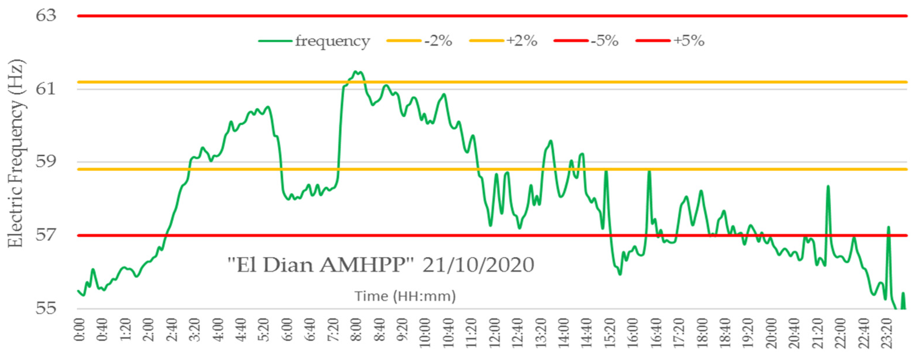
Figure 1 shows a typical behavior [
18] of a Cuban’s AMHPP without frequency regulation.
These problems can be solved using an Electrical Load Controller (ELC) [
26]. The main idea of this approach is to keep the generated electricity constant. According to the user demanded electricity load, a dump load is adjusted to stabilize the electrical frequency. The dump load nominal power is chosen to be 30% higher than nominal load power [
15]. This power rate uses inefficiently the hydro energy source and limit a dump load control to sites with a high water runoff. Cuba has also started to be heavily affected by droughts, causing low rivers runoff [
27]. Due to the effects of the climatic change and in the places with low runoff, as Cuba, it is necessary to minimize the dump load rate.
Other design factors in AMHPP also imply problems in the operation, such as the excessive relationship between pipe length and hydraulic head (L/H), an inadequate moment of inertia (GD
2/4 g), among other factors. All these aspects favor a poor frequency control and low energy efficiency, which results in hydropower plants operating outside their optimum operating point. This fact can be verified in
Figure 1, with the behavior of the electrical frequency generated by a representative AMHPP on a typical day.
The electrical frequency generated in this AMHPP oscillates outside the allowable variation range of ±1% (±0.6 Hz) according to the Cuban standard of Cuba National Electric System (NES) NC62-04 [
16]. The standard applies to the power generation of the entire national territory, including grid connected or isolated.
Due to the size of grids, the energy demands of a large power electrical system represent a small percentage value in comparison to a low-power autonomous system, such as the AMHPP. For this reason, they should not have the same technical requirement regarding their dynamic and quality behavior [
18], although this will not be approached in this work.
Review of the State of the Art
To keep hydropower plants operating at their nominal values, several approaches are reported in the specialized literature, some of which consider the use of mechanical energy storage systems through flywheels [
28], interconnected systems [
29], storage of electrical energy [
30] and use of micro-grids [
31,
32]. Other methods consider the use of asynchronous generators [
33] and isolated micro-grids [
34]. Some of these solutions do not include autonomous systems; therefore, they are not taken into consideration in the scheme proposed in this work. In the most general case, the ac micro-grids integrate the energy supply from several sources, in which the equality of frequencies, voltages, and phases is mandatory for synchronization.
From the operation of AMHPP point of view with the Pelton turbines, two ways of frequency control are known: manipulating the flow of water entering the turbine or adjusting the generator load [
35]. The first method seeks to adjust the operating point of the turbine, regulating the nozzle flow. The 95% of Cuban AMHPP operate with Pelton turbines of TP-15 and TP-16 models. These turbines have limited frequency regulation capabilities due to the high costs of commercial speed governors. Moreover, to avoid problems of transient pressure in the gate, a large value of the setting time of the turbine nozzle is commonly used [
36].
The second method, based on the use of a resistive dump load, ensures that the turbine works at a fixed operating point, the maximum power, balancing the load that represents the demand of the users with a second resistive load connected in parallel [
26]. This method of regulation has a simpler design and good performance against impulse and sustained disturbances. However, in classic designs, the nominal power of the secondary load is chosen 30% higher than the nominal power [
15]. In this case, it is shown that it is profitable only when hot water is required for different uses [
30]. Another drawback is related to the presence of harmonics caused by the rectifier switching, which is solvable by applying filters and switching techniques [
37]. Some research suggests matching the dump load power to the plant nominal power [
38], but at a high cost [
39] and low efficient energy source use. Other authors [
15] propose the reduction of the secondary load to 50% of the nominal power through the adjustment of the turbine flow in fixed amounts of 30% and 50%. In previous investigations [
6], a dump load regulator was designed, with a dump load nominal value of 30%, obtaining good control performance only when is acting sustained disturbances of small amplitude.
By means of a mixed electronic regulator in [
40], a reduction of the dump load to 10% of the generator nominal power is proposed. According to the authors, empirical rules are used, a demand load study is not carried out and nor are evaluated the most frequent types of disturbances. On the other hand, in [
30,
38], a mixed regulation scheme is proposed for flow control by means of on-off valves that instantly increase or decrease the turbine inlet flow by default values of 30% or 50%. In these works, the frequency is maintained according to the parameters designed for sustained disturbances of 2.4% of the nominal power. In [
41], a mixed load-flow regulator is proposed, combining a PI regulator for the dump load control and a fuzzy algorithm to control the nozzle flow, refeeding the frequency measurement. The firmware and hardware based on a micro controller is designed in [
41], but it is not intended to minimize the dump load, does not refer to compliance with the regulations regarding the permitted frequency variations and the design of the control algorithms. These elements indicate that the design of [
41] is not oriented to the efficient use of water. A digital-twin model, can be used to simulate the real time performance of this proposal. The twin can be used to simulate the operation of a piece of equipment or production line in a virtual environment before any production decisions are made. This helps you save on costs and reduces the risks associated with expensive investments [
42].
In [
11] a review of the last 20 articles published in the area of load control is presented, and refers to the need to take advantage of the energy consumed in the secondary load differently, which in the authors opinion could be throw of lighting or some kind of energy storage.
Through previous papers review, it seems that combination of flow and reduced dump load is an intuitive way to use the hydro energy source more efficiently and guarantee the required frequency in nominal values. In this form of operation, it is necessary to adjust the turbine operating point. Load demand fluctuations are compensated thanks to the speed of dump load control, and immediately through flow control, to adjust the operating point of the turbine to the power demanded. With this new method, the system could operate in a regime close to demand instead of operating at maximum power. As a result, energy would be supplied according to quality standards and the water would be used more efficiently by reducing the power of the dump load. The dump load rate would be based on the desired quality requirements of the electric power system (NC62-04 in Cuba), and not on the percent of nominal power installed, which would bring economic benefits by equipment savings and increasing the water efficient use.
3. Proposed Methodology
In this section, the combination of both flow control and dump load control methods are evaluated through a real plant case study representative of the total of autonomous Cuban AMHPP (in Guamá, at Santiago de Cuba province, Cuba). Finally, an evaluation of the dynamic behavior of these plants is carried out through simulation from Matlab
®/Simulink software in which reference models for this type of plant were used [
35,
43].
3.1. Proposed Control Scheme
The installed power (
) of a hydropower station is determined by Equation (1). The operating point at which the turbine operates depends on the values of design hydraulic head (
), flow, through the turbine (
) and turbine efficiency at the nominal point of operation (
). It can be adjusted by linearly changing the Pelton nozzle setting, which will vary the turbine intake flow and efficiency, considering that the hydraulic head remains constant.
The turbine efficiency values are obtained through the characteristic curve of the similar turbine model, according to the turbo-machine similarity theory. The similar turbine model corresponds to the Pelton TP-16 turbine of the Cuban manufacturer “Planta Mecánica”, whose specific speed are 15 rpm and can reach a maximum power of 160 kW.
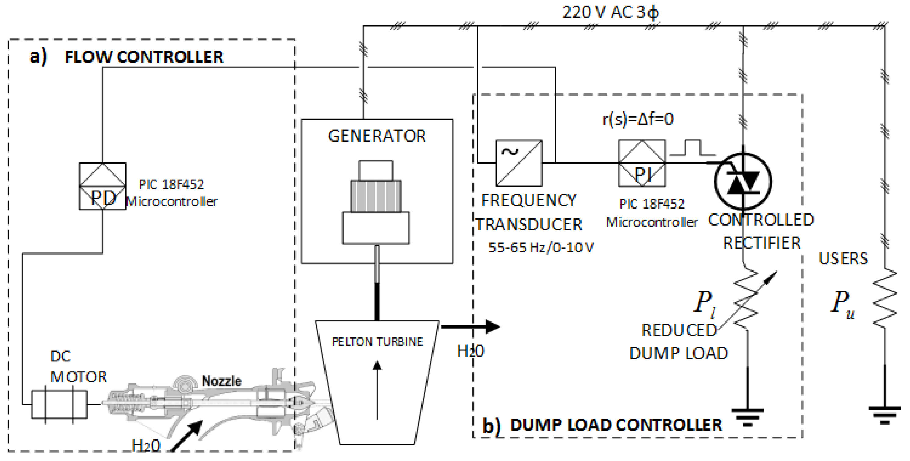
To adjust the operating point of the turbine, through the combined flow-reduced dump load control, the regulation scheme shown in
Figure 2 is proposed.
The scheme consists of two control loops: flow
Figure 2a and dump load
Figure 2b. Flow control adjust turbine operation point only when dump load control can not compensate frequency deviation. The dump load control loop
Figure 2b, keeps the generator power constant only in a limited range of a dump load value, adjusting the power consumed in the resistive dump load, by the controlled three-phase rectifier bridge. The modular value of the change in the dump load is equal to the demanded power change but in the opposite direction. This is only possible when the user load demand amplitude in less or equal than dump load installed.
The flow to the turbine inlet is adjusted to the desired value by means of a servomotor that moves the turbine’s nozzle stem a distance Δl, in a limited range , depending on the value of the frequency measured at the generator terminals.
The turbine operating point is defined by the amount of load demanded (electricity) by the users (
). In addition, the dump load control consists of balancing the increase or decrease of user demanded power through the dump load (
). This point implies that the adjusting of the turbine operating point is defined by Equation (2):
And the decision to adjust the operating point based on the power demanded represented by
depends on function (3).
The magnitude of the adjustment and the minimum value of the dump load installed power depend on the desired behavior of the combined scheme. In this case, it is designed to obtain a maximum steady-state error () of ±1% (±0.6 Hz), settling time () less than 60 s, maximum overshoot () of the error of ±1.5 Hz, in accordance with the Cuban standard NC62-04.
3.2. Model in Transfer Functions
A Proportional Integral (PI) algorithm is used to dump load control, another Proportional Derivative (PD) algorithm to flow control. A PI algorithm is selected to make cero a steady state error of frequency, them, a PD algorithm anticipate an inverse response due to non-minimum phase characteristics of turbine [
35]. These control algorithms were suggested in [
44] for chemical process control with non-minimum phase behavior. A combined control action can produce desired temporal response of electric frequency in accordance with [
16].
The model of the plant considered corresponds to an AMHPP of 100 kW. The parameters of the model correspond to the analytical models determined by [
35,
45] considering small offsets around operation point [
34]. The equations model can also obtain from [
43] considering frequency control mode for the single-machine isolated operation.
Figure 4 show a validation of a model by means of experimental identification.
The values of the model parameters are determined through experimental identification, they were verified in previous works [
6] and are shown in the
Table 1 for the case study.
The constant
is decisive in the dynamic behavior of the turbine. This constant is known as hydraulic time constant. The typical range of variation is [0.5 ≤
Ta ≤ 0.4 s] at full load and varies with the operating point [
35]. For micro-hydro power plants with Cuban Pelton TP-16 turbines, the typical variation range tested experimentally by the authors is [0.4 ≤
Ta ≤ 0.6 s]. It could be considered constant for this case.
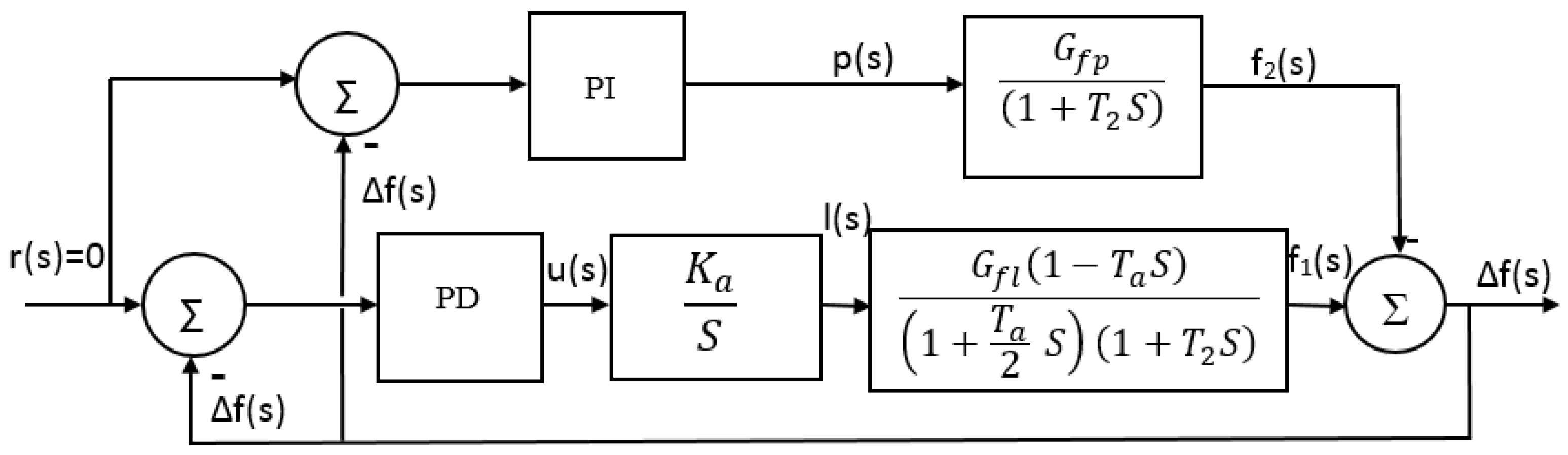
A characteristic of hydraulic turbines, from the point of view of their dynamic behavior, is the presence of a non-minimal phase system [
35], that is a zero in the right complex half-plane (see
Figure 3). This characteristic, together with the restrictions of the required minimum closing time of the intake elements, means that the PD regulator of the proposed scheme must be properly designed to avoid water hammer.
Equation (4) represents the transfer function of DC servomotor.
Considering
[
46], a DC servomotor will approximates to integral. The integral term in the transfer function or servomotor represents physically the offset to constant speed of the Pelton turbine stem nozzle. This integral term makes a classical PID control algorithms for flow control.
A reference signal r(s) represents frequency set point, is set to cero because deviation model is considered (cero means, no frequency deviation around 60 Hz).
3.3. Tuning of Dump Load and Flow Regulators
Taking into account that dynamical response of the dump load control loop is slowly than the flow control loop, the combined control loops can be designed independently.
The tuning of the two regulators (flow and load) is carried out separately through the pole placement method like [
22], ensuring that the desired frequency behavior complies with Cuban standard NC62-04.
Increase hydropower inertia response by adding flywheel could be a solution [
26,
29], but dump load control causes similar effect and is more flexible. In [
47] its proposed that the mechanicals inertia is as minimum 4 times that of the hydraulic circuit inertia. This dynamical response rate could be taken as advantage in the design of the combined flow-dump load control. Similar resistive loads are utilized in grid connected systems [
48] to suddenly shutdown in load rejection.
Definitively the dump load regulator is faster because the time constant depends on electronic elements. Since it is desired to obtain zero error at steady state in the behavior of the frequency, an integral proportional regulator (PI) is designed. This regulator must reject the load disturbances of great magnitude. For this reason, a settling time (
) is required 4 to 6 times less than the settling time of the flow regulator,
and
. In the case of the flow regulator, the presence of a non-minimum phase system implies the use of an anticipatory action (derivative action). However, the integral action is present because the dynamic characteristic of the servomotor valve is integral type as can be seen in
Figure 3. It can be verified that the flow regulator PD follows Equation (5).
Since flow regulator acts only when
, the temporary restrictions for the flow control are small than the dump load control. It corresponds to the limits established in the NC62-04. The proportional action constant values (
), integral action time constant (
), and derivative action time constant (
) according to the case, are determined. The dominant poles of the closed-loop transfer function generates a similar behavior to the second-order polynomial (Equation (6) for dump load control) and third-order regulator (Equation (7) for flow control).
As poles are related to damping factor (
), settling time (
) and maximum overshoot (
) for an underdamped system (
). Matching the characteristic polynomial of the closed-loop transfer function
for the dump load control, and
for the flow control, with the corresponding desired polynomial. The expressions of the PI regulator and the PD regulator time constants shown in
Table 2 are obtained.
Table 2 shows for each regulator the summary of the values of the conjugate complex poles according to the desired temporal response. Also shows, the expressions of calculation of the control algorithms time constants, as well as their corresponding values.
Given the possibilities offered by Matlab
®/Simulink, the final location of the dominant poles and the calculation of the control parameters they were refined using the trial and error method. For this reason, the values shown in
Table 2 are not exactly the result of the equations, but rather show small variations of about 5% error.
3.4. Types and Magnitudes of Disturbances
According to the load studies carried out in [
49] by the authors, impulse load disturbances are associated with electrical equipment that by its nature demands high electrical consumption in a short time interval, e.g., electric arc welding or motor starting in the existing mini-factories. Most of a load of household appliances and lighting are considered sustained loads and as such are modeled in this research. The magnitudes of the disturbances are designed from the analysis of the behavior of the loads, obtained from previous studies [
6]. Therefore, the analysis of the electric frequency temporal response is relevant for the following cases:
When the duration of impulse load disturbances varies between 2 and 3 s. To make sure a capacity of reject impulsive loads.
When the power required by users does not exceed the dump load nominal value . To test the capacities of dump load control alone.
When the power required by users exceeds the dump load nominal value . To test the capacities of combined control in most general case.
When the amplitude of the sustained disturbances is much bigger than dump load amplitude. To test the capacities of combined control in a limit special case.
Table 3 shows the types, magnitudes and times at which the simulated disturbances is acting.
According to the loads types that are usually present in these isolated power generation systems [
6,
49], a dynamic behavior in the case of impulse type disturbances of great amplitude and short duration is simulated (
Table 3 cases 1 and 2). As well as of the sustained type of small amplitude in relation to the generator power, case 3. The dynamic behavior is also simulated in the event of sustained disturbances of up to 15.5%, case 4.
4. Results and Discussion
4.1. Results for Impulsive Loads. Cases 1 and 2
Figure 5a shows the temporal response to the separately dump load and flow control, and in
Figure 5b the behavior of the frequency of the combined flow-dump load control.
In Cases 1 and 2, with the magnitudes of the impulse type disturbance of up to 11% of the nominal power, dump load control alone stabilizes the frequency in 3 s. It could be considered instantaneous compared with the 60 s of the flow controls. Dump load control is suitable only when there is a hot water demands. In this case, the dump load nominal value of 100% of generator value is required, implying inefficient water use. When user load demand is greater than 11%, the frequency variations are greater than 1 Hz, so they would be outside the norm considered.
As shown in the previous figures, the dump load control has a dominant effect for Cases 1 and 2. However, from the point of view of the rational use of energy, the efficiency of the combined control action could be increased, as the value of the dump load installed decreases.
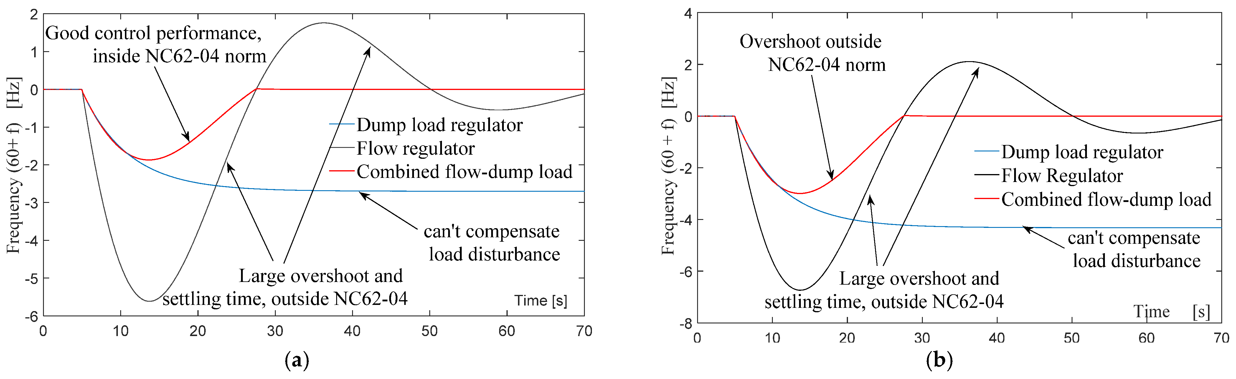
4.2. Results for Sustained Loads. Case 3 and Case 4
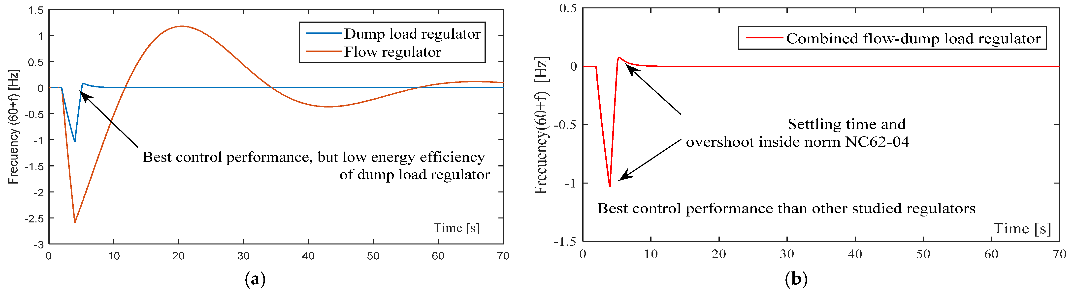
For sustained disturbances amplitudes up to 10%, the frequency behaves within the limits allowed only for combined flow-dump load regulation, as shown in
Figure 6a.
Flow control alone converges to its desired frequency value, but, very slow and with variations greater than those admitted in the NC62-04 standard. Similarly, dump load control by itself, not compensates the disturbances whose magnitude is greater than ±3 kW, this conclusion is derived from (2).
Figure 6a, show that the settling time is smaller than 25 s and the maximum overshoot is minor than 1.8 Hz (3%) only by means of combined flow-dump load controller. This behavior confirms the possibility of to give better dynamic response of flow control, through the combination of flow and reduced dump load control schemes. At the same time, can increase the energy efficiency, ensuring frequency temporary response inside technical standards.
When the load disturbance amplitude is up to 12%, considered excessively large limit, but possible in Cuban isolated power systems, the settling time remains. However, the overshoot increases by 5% equivalent to 3 Hz, which is outside the established norm, as the
Figure 6b shows.
Combined flow-dump load control scheme is best solution than others, as showed Cases 1 to 4. Nevertheless, is necessary to reduce a dump load value to guarantee water savings and therefore energy source efficiency.
4.3. Reduction of a Dump Load Value
From the authors point of view, the optimum dump load value is the minimum value of dump load installed that compensates for the maximum variation in the users load demand, inside the temporary limits stated in the power quality norm used. Therefore, it can be found the maximum amplitude of impulsive
and sustained
load disturbances from the users load study. In addition, maximum
and minimum
instantaneous demanded power is measured.
Table 4 summarizes a user load study [
49] of two AMHPP in Santiago de Cuba province, Cuba.
An installed maximum dump load value
is determined from (8), where
is a security factor that ensures low measuring errors.
Security factor
is determined by doing simulations; it is the minimum value that guarantee a required frequency deviation referred in NC62-04 (<1%).
Figure 7 show a
selection by simulations. For the case study being analyzed, the dump load to install is reduced to 7.5 kW, which is a 7.5% of the nominal power as a result of the combined flow-dump load control action.
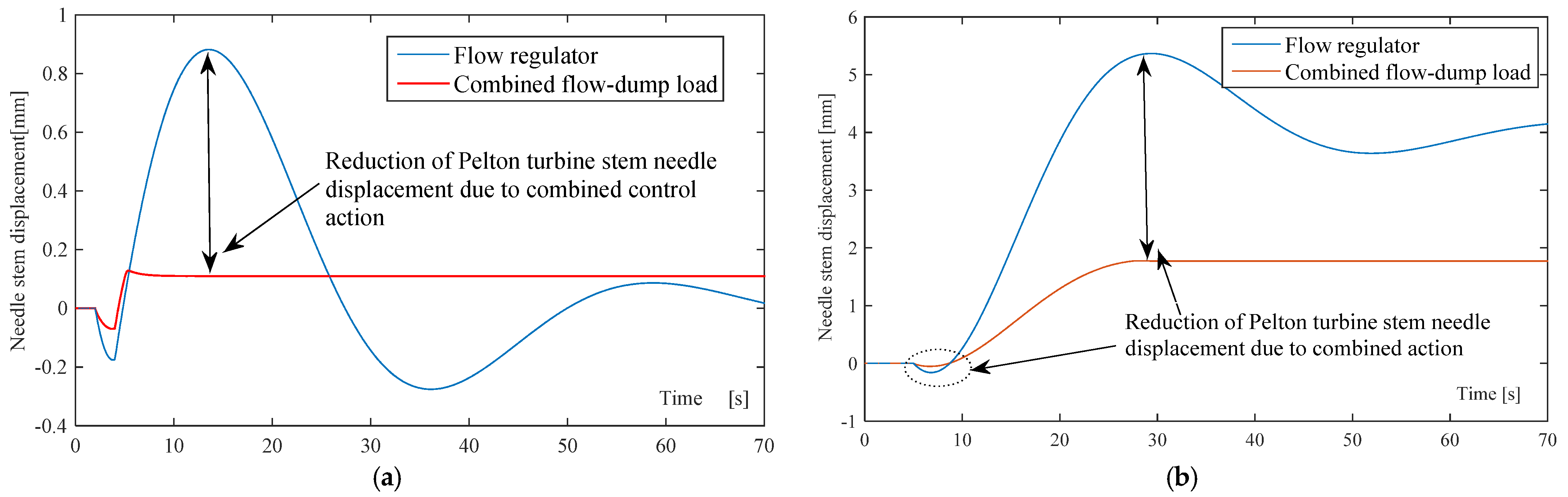
4.4. The Offset of the Turbine Stem Nozzle
When the dump load and flow controllers are combined, the offset of the turbine stem nozzle is reduced considerably in the presence of impulsive disturbances as shown in
Figure 8a for Cases 1 and 2. In comparison with the flow regulation alone, the combined flow-dump load control action reduces the frequency settling time and the overshoot by 4 and 3.2 times respectively (see
Figure 8a).
For sustained load disturbances, Cases 3 and 4, the slope of the offset of the Pelton turbine stem nozzle is reduced, which leads in a “softer” and physically realizable action. This helps to avoid abrupt closures and undesirable consequences like water hammer (see
Figure 8b).
These simulations show that the optimal solutions for AMHPP are a challenge to achieve good performance results with low costs and high energy efficiency. The reduction of the resistive dump load through the combined flow-dump load control method is suitable to increase the energy efficiency of AMHPP.
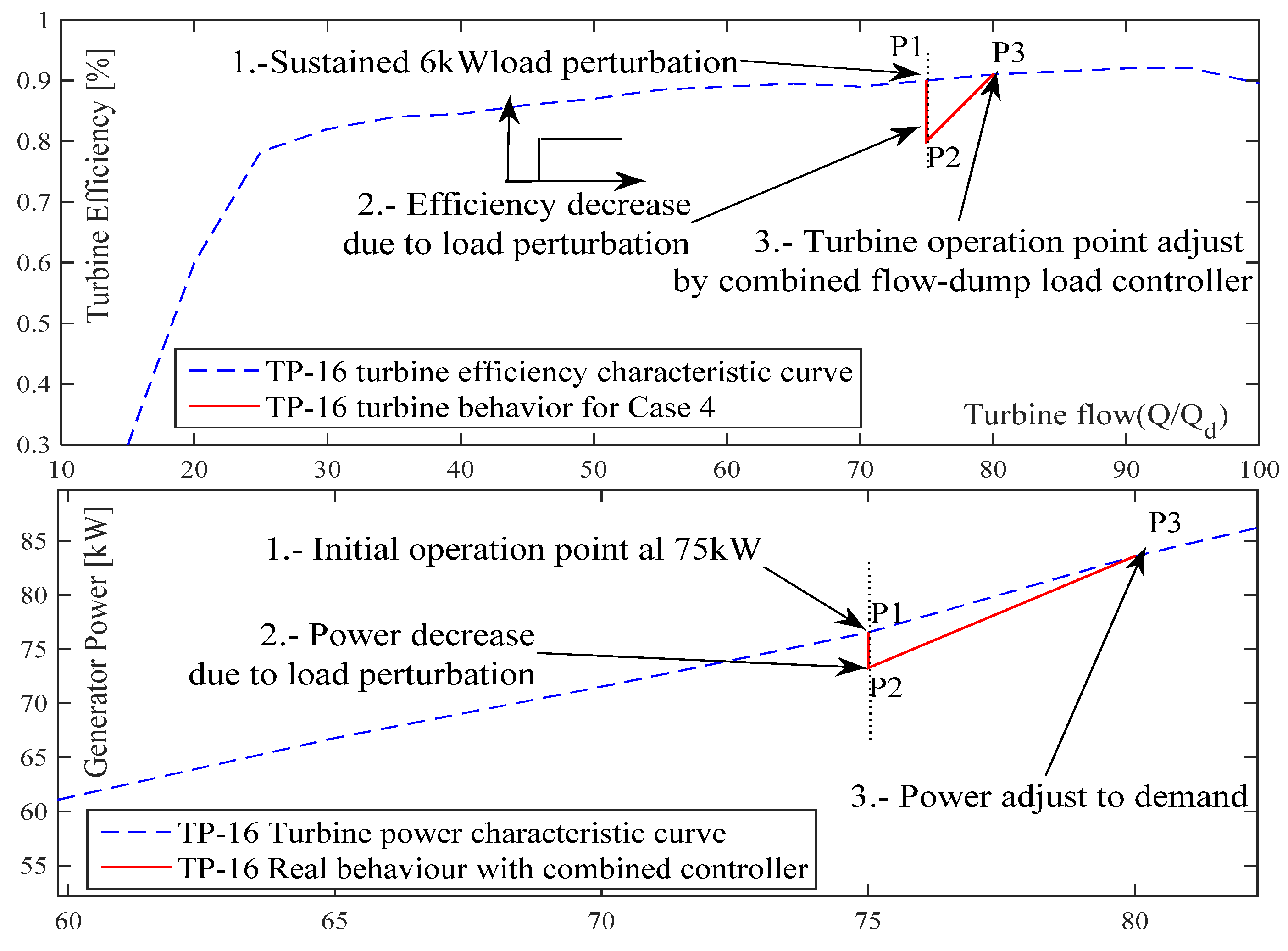
4.5. Energy Efficiency Improvement
Figure 9 shows a behavior of a Pelton turbine efficiency and the generator power versus turbine inlet flow. A Case 4 is plotted too in
Figure 10 when TP-16 turbine operates at 75 kW in “El Dian” AMHPP case study.
When sustained load disturbance occur in P1, the turbine speed and electric frequency decreases at new turbine efficiency and power P2 (
Figure 9). The corrective signal of dump load controller diminishes a dump load value according to Equation (2). But, in correspondence with Equation (3) it is needed to adjust the turbine operation point by flow controller, because load disturbance is greater than dump load at steady state (7.5/2 kW).
If only dump load controller is acting, the electric frequency will not stabilize (
Figure 6a,b) and turbine will work in a less efficient curve in accordance with
Figure 9, P2 point. The turbine efficiency decreases from 0.89 to 0.8 in P2 point as
Figure 9 show. The combined flow-dump load action guarantees to operate in maximum TP-16 turbine efficiency curve (P3 point), adjusting the turbine operation point instead work at maximum power of dump load controller.
Overall energy efficiency of combined action is indeed less than flow controller alone because it dumped 7.5 kW more as show
Figure 10. Moreover, micro-hydropower dynamic response will increase, as shown in
Figure 6a,b because diminishes settling time considerably. Finally, water efficiency will increase because it dumped a reduced power (7.5%), therefore more water can be used to serve users demands.
In “El Dian” AMHPP case study, the water and electricity savings were calculated and showed in
Table 5. With a water saved due to the use a combined action, a water to energy efficiency will increase to 0.82 as shown in
Table 5.
In future works, the authors intend to develop other approaches to increase the quality of the electrical energy generated by these plants. It could be the replacement of the dump load by energy storage or lighting. In this way, the energy dumped in the resistive load could be stored as electrical energy, to be used in irrigation, water supply or in public lighting systems in rural areas.
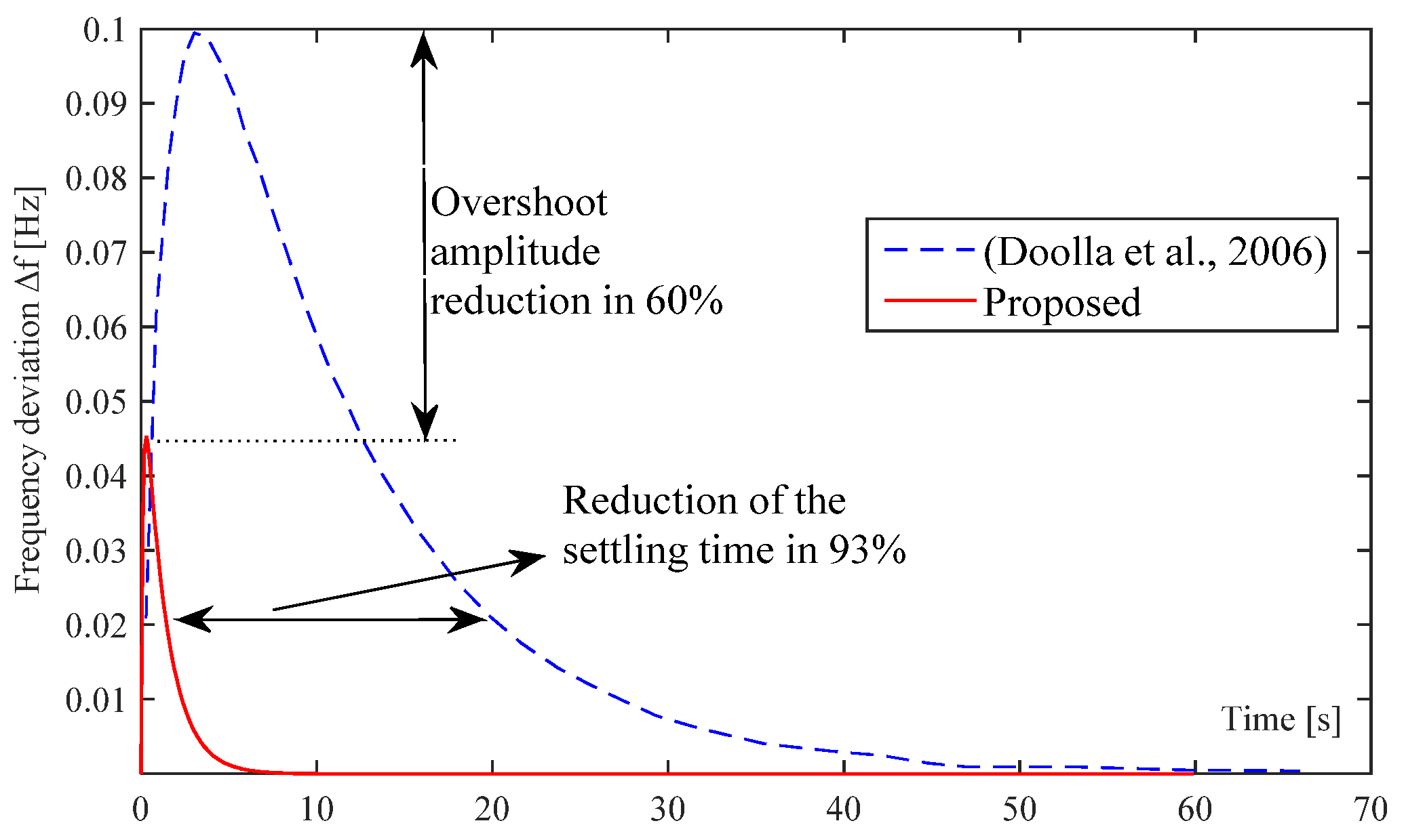
4.6. Results Validation
As validation, a comparison with a results of [
15] is done. In
Figure 11 is shown the electric frequency behavior by a proposed combined flow-reduced dump load versus the values obtained in [
15].
The simulations conditions was obtained from [
15], it consider a sustained load disturbance of 2.4% of nominal power. As show
Figure 11, the combined flow-dump load frequency control proposed reduce the maximum overshoot and settling time in 60 and 93% respectively. In order of relevance, some key aspects influence in these results:
To combine flow with a reduced dump load control, making that dump load control loop responds from 4 to 6 times faster than flow control loop.
To make a study of user load demand, possible in micro power systems like AMHPP.
To vary nozzle flow linearly instead of discrete in 30% or 50% rates.
5. Conclusions
The simulation results have shown that frequency control in AMHPP with the limits states of NC62-04 norm is guaranteed, if proposed combined flow-reduced dump load control scheme is used. In addition, it is possible to increase energy efficiency in the AMHPP by reducing the value of the resistive dump load by up to 7.5% in a case study. A user load demand study plays a necessary role in the dump load reduction and controllers design.
The NC62-04 standard, which considers connected and isolated power plants on equal terms, could be modified to allow possible frequency variations in AMHPP by up to 2% without deteriorating control requirements.
The combined flow-reduced dump load action allows more efficient use of the energy resource, especially in hydro plants where runoff does not allow working at maximum power. In future works, will address the substitution of the resistive dump load by other methods that uses the energy source more rationally, like energy storage.


 ,
, 


