Article

Selection of Underground Hydrogen Storage Risk Assessment Techniques

by
Barbara Uliasz-Misiak
*,
Joanna Lewandowska-Śmierzchalska
and
Rafał Matuła
Faculty of Drilling, AGH University of Science and Technology, Oil and Gas, Mickiewicza Av. 30, 30-059 Krakow, Poland
*
Author to whom correspondence should be addressed.
Energies 2021, 14(23), 8049; https://doi.org/10.3390/en14238049
Submission received: 30 October 2021 / Revised: 24 November 2021 / Accepted: 29 November 2021 / Published: 1 December 2021

Abstract

:
The article proposes the use of the analytic hierarchy process (AHP) method to select a risk assessment technique associated with underground hydrogen storage. The initial choosing and ranking of risk assessment techniques can be considered as a multi-criteria decision problem. The usage of a decision model based on six criteria is proposed. A ranking of methods for estimating the risks associated with underground hydrogen storage is presented. The obtained results show that the application of the AHP-based approach may be a useful tool for selecting the UHS risk assessment technique. The proposed method makes it possible to make an objective decision of the most satisfactory approach, from the point of view of all the adopted decision criteria, regarding the selection of the best risk assessment technique.

1. Introduction

Hydrogen is a very good energy carrier, a “clean” fuel (its combustion produces only energy and water) and can be an energy store. The use of hydrogen as an energy carrier can play a major role in a carbon neutral economy. This can be hydrogen produced from renewable energy by electrolysis (“green hydrogen”), natural gas or carbon with CO2 capture (“blue hydrogen”) [1].
Hydrogen will also allow the decarbonisation of economic sectors where reducing carbon dioxide emissions is difficult to achieve. This element can replace natural gas in the chemical, metallurgical and transport industries, and in the long term also in the aviation and maritime sectors.
It is predicted that in the near future, energy is to be obtained mainly from renewable sources (RES) (wind and solar power plants). The introduction of the hydrogen economy will allow an increase of the share of renewable energy in the total energy balance thanks to the possibility of storing energy of multi-megawatt power, e.g., by conversion to hydrogen.

1.1. Hydrogen Storage

Hydrogen can be stored in various ways in metal tanks on and below the ground surface, in gas networks as a mixture of H2 with natural gas, in materials or underground in deep geological structures. Underground hydrogen storage facilities should distinguished by high storage capacity, technological simplicity, low costs and safe operation [1,2,3].
Gaseous hydrogen can be stored in tanks on or below the ground surface. In the case of large volumes, storage in above-ground pressure vessels entails high investment costs. On the other hand, the storage of hydrogen in underground metal tanks requires close supervision due to corrosion, which is difficult to control underground. Hydrogen from renewable sources can also be stored in gas networks as a mixture of hydrogen and natural gas (Power-To-Gas technology). However, due to the properties of the gas mixture (after adding hydrogen to it) being significantly different from the properties of natural gas, its common usage requires research to ensure the safety of gas networks and gas consumers [3,4,5].
One option currently being explored is hydrogen storage in solid materials (alloys and composites). In this way, up to 6–7% the weight of the hydrogen material can be stored in the solid. Hydrogen can be stored in metal hydrides, in chemical compounds formed by chemical reactions and in porous carbon materials (activated carbon, fullerenes, graphite or carbon nanotubes) [6].
Underground storage of this gas in geological structures is currently considered to be the most promising form of hydrogen storage. Underground gas storage facilities can be located in salt caverns, depleted hydrocarbon deposits and aquifers. Storage sites in such geological structures have numerous advantages over other storage options. The most important are the ability to store large amounts of gas and the safety of storage. Particular types of geological structures differ from each other. The factors that have the greatest impact on the hydrogen storage process are: the universality of the geological structures considered for storage, the tightness of the underground storage, geochemical and microbiological interactions with reservoir fluids and the rock matrix, the amount of working gas and cushion gas, and storage efficiency [7].
There are many years of experience with underground natural gas storage, in porous rocks (depleted hydrocarbon deposits and aquifers) and salt caverns. On the other hand, experiences with underground hydrogen storage are small and concern storage in salt caverns [8,9,10]. Pure hydrogen (95% H2) is stored in salt caverns in the United Kingdom (Teesside in Yorkshire) [11], the US (Clemens, Moss Bluff and Spindletop) [12] and Russia [13]. We have less experience with underground hydrogen storage in porous geological formations. Practical applications are limited to storing town gas in aquifers (25–60% H2, 10–33% CH4, 12–20% CO and CO2 and <30% N2), e.g., in Beynes (France) or Lobodice (Czech Republic) [14,15]. The hydrogen-containing gas storage facilities are also located in depleted natural gas fields in Argentina (pilot project for hydrogen storage in the Diadema field) [16] and Austria (project “Underground Sun Storage” for storing gas containing 10% hydrogen) [9,17].

1.2. The Hazards of Underground Hydrogen Storage

Safety is a fundamental issue in the location, operation and closure of underground hydrogen storage facilities. It is related to the effectiveness of gas retention in an underground storage facility for the storage period (the lowest possible losses related to its leakage towards the Earth’s surface and the composition of the stored gas). The safety is influenced by the physical and chemical properties as well as selected geological and deposit conditions of the storage formation (reservoir rock and overburden). The quality of the overburden rocks, its lithology and tectonic deformations are of particular importance.
The experience in field of natural gas (UGS), compressed air (CAES) and carbon capture and storage (CCS) can be transferred to underground hydrogen storage. However, the different physical and chemical properties of hydrogen compared to other gases stored underground, reactions with minerals and fluids, potential microbiological interactions, or geomechanical aspects affecting the safety and efficiency of underground hydrogen storage make it impossible to directly transfer these experiences to H2 storage. Therefore, the geological structures in which hydrogen is to be stored require detailed analysis, including the determination of any uncertainties and risks related to potential leakage and other hazards [7,18,19,20].
Gaseous H2 is characterized by high permeability, high air-viscosion coefficient in excess of air and low dynamic viscosity [21,22]. The high mobility and permeability of this gas causes a greater risk of migration outside the storage and the possibility of migration through the sealing rocks [7]. Low hydrogen viscosity increases the risk of the formation of viscous fingering in the warehouse, resulting in the formation of zones of unrecoverable hydrogen [23], which negatively affects the amount of gas withdrawn.
The hydrogen injected into the underground storage facility will interact with reservoir rocks, the fluids filling these rocks, as well as with the rocks of the sealing overburden. These impacts will depend on the mineral composition of the rocks and the chemical composition of the reservoir fluids. Dissolution of minerals in reservoir rock may increase its porosity and permeability [24] and lead to weakening of its mechanical strength or activation of faults [20,25]. Hydrogen can also act on sealing rocks, dissolution of minerals and sorption/desorption of clay minerals in these rocks, creating gas migration pathways through the overburden [20,26,27,28].
Similar effects were found in the case of underground gas storage. Modelling of the effect of CH4 adsorption and diffusion processes on the sealing quality of a natural gas storage site have shown that diffusion deformations reduce the permeability of the overburden rocks [29]. Studies on interactions between matrix and gas of dual-porosity reservoir of hydrogen and carbon showed that increasing the fracture permeability increases gas depletion, and the processes of desorption from the matrix allow gas to be exploited for a long time [30].
Various gases, including hydrogen sulphide, may be produced when H2 is stored.
This gas will reduce the quality of the stored hydrogen and modify the water chemistry (redox potential and pH) [31], causing further fluid-rock reactions [20]. The interactions between the gas and groundwater may also pose a threat to the quality of the stored hydrogen. This gas can change the chemical balance between the brine and the rock matrix. This will affect the operation of the underground warehouse. Geochemical reactions can also lead to the loss and contamination of stored hydrogen [32]. Underground gas storage in deep aquifers are environments of potentially high abundance and microbial activity, with microorganisms that are hydrogen consumers [33]. Microorganisms can use hydrogen in their metabolism, which can lead to various undesirable effects such as loss of hydrogen [34,35,36], gas or acid formation [37]), loss of porosity [20,38] and corrosion [37,39].
The geomechanical influences also influence the safety of underground hydrogen storage. Injection of hydrogen into the underground storage will lead to an increase in pressure (changes in stresses) that may cause deformation of the rock mass [40]. Stress fluctuations can cause reservoir rock compaction (reduced porosity and permeability) [41,42], subsidence [43], fault reactivation [44] and micro-seismicity. Compaction of reservoir rock can lead to fracture formation and thus migration pathways for hydrogen in the overburden rocks [20].

1.3. Risk Assessment Techniques

Risk is defined as the effect of uncertainty on objectives [45], where objectives may relate to various aspects of the activity, e.g., financial or environmental. Risks can be defined in terms of potential events, their sequelae, or a combination of both. It is often expressed as a combination of the consequence of an event and the associated probability (possibility, chance) of it occurring. Uncertainty, on the other hand, means the state of lack of information related to the understanding or knowledge of an event, its consequences or probability. The influence of uncertainty causes a deviation from expectations, which can be positive and/or negative. The risk-based approach is essential for achieving the intended results, increasing the desired effects and limiting or preventing the occurrence of undesirable effects, as well as achieving improvement [46].
Risk management are activities related to the direction and supervision of an organization in relation to risk. One of the key elements of risk management is risk assessment. Risk assessment is the process of identifying, analyzing and evaluating risk. Risk identification allows you to determine the sources of risk and predict their potential impact. Risk analysis provides data for risk evaluation and for making decisions on how to deal with risk, usually taking into account the probability of risk consequences and the effects of these consequences. Risk evaluation is a comparison of the results of the risk analysis with risk criteria understood as reference levels against which the significance of the risk is determined [46].
Many techniques of risk assessment are described in the professional literature, using both traditional methods and computer techniques; each of them has certain advantages and disadvantages. The range of available methods is very wide, ranging from descriptive methods and simple classification based on risk assessment divided into high, medium and low, to methods based on complex calculations.
The ISO/IEC 31010 Risk Management—Risk Assessment Techniques standard [46] describes over 30 different instruments such as: methods, models, techniques and tools supporting the risk management process. They illustrate the full range of risk assessment methods, from expert considerations to methods based on building patterns and logical scenarios of events. Risk assessment tools and techniques have been divided in terms of their possible use at particular stages of the process. Tools and techniques have been distinguished that can be used for the purposes of: risk identification, risk analysis and risk evaluation [46,47].
ISO 31010 classifies risk assessment techniques according to their primary use in risk assessment. The following techniques are distinguished in it:
  • eliciting views from stakeholders and experts, (e.g., Brainstorming, Delphi technique, Interviews);
  • identifying risk (e.g., Check lists, Failure modes and effects analysisFMEA/Failure modes and effects and criticality analysis FMECA, Hazard and operability studies HAZOP);
  • determining sources, causes and drivers of risk (e.g., Ishikawa method, Root cause analysis);
  • analysing existing controls (e.g., Bow tie analysis, Hazard analysis and critical control points HACCP);
  • understanding consequences and likelihood (e.g., Fault tree analysis, Cause-consequense analysis, Monte-Carlo simulation);
  • analysing dependencies and interactions (e.g., Cross impact analysis);
  • providing measures of risk (e.g., Data protection impact analysis, Value at risk);
  • evaluating the significance of risk (e.g., ALARP—“as low as reasonably practicable”, Pareto charts);
  • selecting between options (e.g., Decision tree analysis, Multi-criteria analysis);
  • recording and reporting (e.g., Consequence-likehood matrix, Bow-tie).

1.4. The Importance of The Discussed Issues

Hydrogen is now considered a key contributor to a climate-neutral, zero-polluting economy by 2050; moreover, it can replace fossil fuels and materials in hard-to-decarbonise sectors. The high potential of hydrogen results from the possibility of storing excess electricity from renewable sources, supporting seasonal fluctuations in electricity production from RES and connecting production sites with places of demand. One of the components of the hydrogen economy chain is the large-scale underground storage of this gas. Among the geological structures where hydrogen storage can be located (salt caverns, depleted hydrocarbon reservoirs and aquifers), we have the most experience with storage in salt rocks. Underground hydrogen storage in aquifers is a technology that has not been used on an industrial scale so far. This technology will be developed due to the fact that the aquifers make it possible to locate hydrogen storage sites with capacities several times larger than salt caverns [7].
The properties of hydrogen mean that storing this gas is more risky than storing natural gas. This risk is associated with easier H2 migration and geochemical and microbial activity compared to methane. In particular, the creation of hydrogen storage in aquifers requires an assessment of the risks associated with this type of activity. In order to properly manage the risk, it is important to select the appropriate risk assessment method. So far, no risk estimation method has been proposed that takes into account the specificity of underground hydrogen storage in aquifers. In this article, the authors analyzed selected risk assessment techniques (most commonly used in the oil industry) in terms of choosing the best risk assessment method for underground hydrogen storage.

2. Materials and Methods
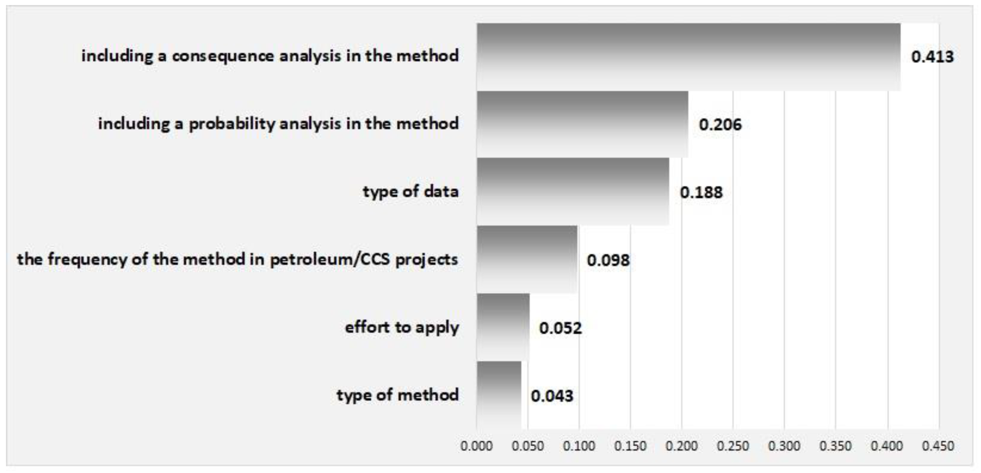
2.1. Materials

The method of selecting a technique for estimating the risk associated with underground hydrogen storage was developed based on specially selected criteria. The criteria used in the decision-making system were developed on the basis of the characteristics of risk assessment methods. Based on the ISO 31010 standard, the following factors were taken into account for the selection of an appropriate risk assessment technique: the objectives of the case under consideration, the needs of decision makers, the type and size of the analyzed risk, the potential size of the impact, the availability of information and data, the need to modify/update the risk assessment and finally regulatory and contractual requirements. The criteria indicated by the authors are listed in Table 1.
The following criteria were taken into account in the decision-making system to evaluate the techniques for assessing the risk of underground hydrogen storage, among those listed above:
  • type of method,
  • the frequency of the method in petroleum/CCS projects,
  • type of data,
  • effort to apply,
  • including a probability analysis in the method,
  • including a consequence analysis in the method.
The decision-making system also requires the indication of possible decision variants. In this paper, the mentioned variants are risk assessment techniques.
In order to select decision-making options, publications in the onepetro.org database on risk methods used in the oil and gas industry were analyzed. Onepetro is a full-text database of technical literature, in the fields of petroleum geology, geophysics, drilling, reservoir engineering, exploitation of crude oil and natural gas, underground gas storage and CO2 storage. We searched for publications published after 1 January 2011 which concerned risk assessment. The key words were methods of risk assessment (20). The largest number of publications concerned the application of the Monte Carlo method (442), hazard and operability studies (HAZOP) (342), bow-tie analysis (175) and failure mode and effect analysis (FMEA) (134). Other methods have been analyzed in fewer publications: 8 risk assessment methods: Fault tree analysis (FTA), Check-lists, Root cause analysis (RCA), Scenario analysis, Event tree analysis (ETA), Reliability-centered maintenance (RCM), Layers of protection analysis (LOPA), Functional Safety, Preliminary hazard analysis (PHA), in 48 to 67 publications, 4 methods: Delphi technique, Human reliability analysis (HRA), Fishbone diagrams, Bayesian analysis in 20 to 28 publications and 3 methods: Cause/consequence analysis, Cause-and-effect analysis and Hazard analysis and critical control points (HACCP) in 5 to 11 publications.
The analysis was carried out for the methods most often found in publications in the Onepetro database and belonging to various groups of risk assessment techniques listed in the ISO 31010 standard [46]. The following methods were selected:
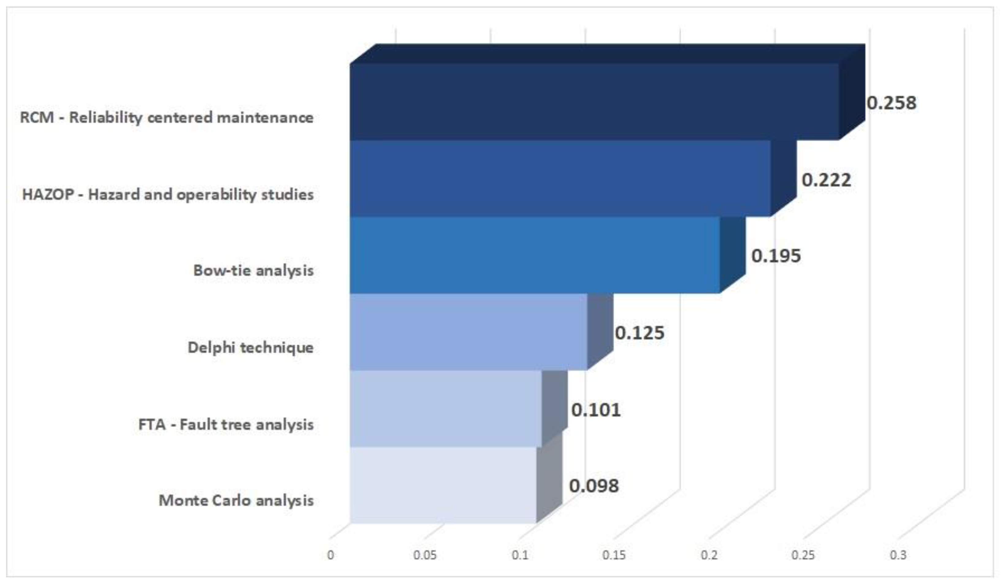
  • Delphi technique (on the basis of a set of opinions/views it determines the convergence of experts’ opinions on a given matter).
  • Hazard and operability studies (HAZOP) (performed on the basis of a list of keywords that generally suggest all possible types of deviations from the normal state).
  • Fault tree analysis FTA (using the structure of logical trees, allowing modeling of the failure course and subsequent analysis).
  • Reliability centered-maintenance (RCM) (identification (and then planning and implementation) of preventive and corrective actions to ensure the appropriate level of equipment reliability, with the minimum use of resources, provided that the safety of equipment, personnel and environmental protection requirements are met).
  • Bow-tie analysis (a schematic description and analysis of the development paths of an event from cause to consequence; it focuses on the barriers between causes and events as well as the event and its consequences).
  • Monte Carlo analysis (the construction of such a random process, the distribution parameters of which are equal to the quantities sought for a given problem).
For the above-mentioned risk assessment techniques, the characteristics of the criteria used in the further analysis are presented (Table 2).

2.2. Methods

The problem of choosing a method for assessing the risk associated with underground hydrogen storage, like most decision problems, has a multi-criteria nature. It requires analyzing its structure, determining a set of decision alternatives and a set of criteria. In this work, the method of the analytical hierarchical process (AHP) was used to construct the decision model due to its effectiveness in solving various problems, confirmed in the literature [48].
The AHP method was developed by Saaty [49,50]; it combines concepts from the fields of mathematics and psychology. The decision problem in the AHP method is presented in the form of a tree. At the highest level of the hierarchy there is the superior (main) goal, and at the lowest level—the considered decision alternatives. Intermediate levels (branches) are the considered component factors of the problem (decision criteria) that affect the degree of achievement of the overarching goal and the choice of the best alternative [51].
The main goal is to identify the best method to assess the risk of underground hydrogen storage. The final criteria were selected taking into account the characteristics of the risk assessment methods and the specificity of hydrogen storage in aquifers. Possible decision alternatives in the form of six selected risk assessment methods were adopted.
After constructing the hierarchical decision structure, a diagram of the decision system was developed (Figure 1). Assessments were generated from the mutual comparison of criteria (global preferences) and considered alternatives (local preferences). A series of pairwise comparisons were made of elements located at each level of the hierarchical model. A nine-point rating scale from 1 (no dominance) to 9 (absolute dominance) (Saaty scale) was used to determine dominance. This scale assigns natural numbers and a verbal description to individual grades. They express the expert’s subjective preference for one of the pair’s components compared to the other [51]. The evaluation matrix for the criteria was determined by comparing the individual criteria in pairs. Then, the individual decision alternatives were assessed, due to the adopted criteria, by comparing the alternatives in pairs and determining their degree of domination against each other also using the Saaty scale. Based on the calculated partial utility vectors of the alternatives, an aggregated final preference vector was found for the considered decision alternatives. A ranking of alternatives was obtained and the most favorable one from the point of view of the considered criteria was selected.
After all pairs of objects were compared, the consistency (concordance) of the scores was checked for each comparison matrix, based on the maximum eigenvalue found for the comparison matrix by calculating the consistency ratio CR. This coefficient is the quotient of the consistency index (CI) and the random consistency index (RI) [52]. The random coherence index is computed from a randomly generated matrix of dimension n × n. RI values were estimated from 10,000 matrices. According to Saaty, the CR value for 3 × 3 matrices must be less than or equal to 5%, for 4 × 4 matrices it should be 8%, and for larger matrices it should not exceed 10% [49,53]. Hence, it is assumed that if the CR value is less than 0.1 (10%), the consistency ratio is acceptable, the comparisons are consistent (concordant) and expert judgments can be accepted [52]. It is then assumed that the comparison matrix is consistent.

3. Results and Discussion

The main objective of the proposed methodology is to identify the best technique for assessing the risk associated with hydrogen storage in aquifers. In the first step, the evaluation matrices for the criteria were determined by comparing the individual criteria in pairs. Their validity was assessed on the basis of the expert opinion of the authors of this article. Determining the importance of individual elements was carried out in accordance with the principles of the pairwise comparison method, by determining the degree of dominance of one criterion over the other. For the adopted decision criteria, on the basis of the evaluation matrix, the vector of weights was calculated. The weights obtained for the criteria make it possible to indicate the most important criteria from the point of view of the overarching goal. The most important criterion in the obtained ranking is “including a consequence analysis in the method” with a weight of 0.413 (Figure 2).
The weight vector for the criteria was verified according to the principles of the AHP method. For this purpose, the consistency ratio of the analyzed matrix was calculated, which was CR = 0.0373. Due to the fact that this coefficient is lower than the adopted threshold value of 0.1, the experts (authors) assessments collected in the comparison matrix for decision criteria are consistent, and the obtained vector of weights can be used in further decision analysis.
Then, individual decision alternatives were assessed, taking into account the adopted criteria. In order to determine the evaluation matrix of alternatives with respect to individual criteria, each criterion was assigned by scores from the adopted scale. The ratings were established on the basis of predetermined ranges of possible numerical values that may be assumed by a given criterion against all decision alternatives. The individual criteria were assigned specific numerical values or values from a scale of 1 to 5 or 1 to 3 (Table 3).
Based on the evaluation matrix, the weight vectors representing the distribution of importance of individual alternatives were calculated, taking into account subsequent criteria (Table 4). All obtained vectors of weights, for the matrix of comparisons of alternatives with respect to each other, were verified by calculating the consistency ratio. All the coefficients are lower than the adopted threshold value of 0.1, and hence the comparison matrices are consistent (see Table 4).
Taking into account the values of the weight vectors, it was found that the RMC risk assessment method has the highest priority for the “type of method” criterion (0.463), the Monte Carlo analysis—for “the frequency of the method in petroleum/CCS projects” criterion (0.397), the Delphi technique—for the “type of data” criterion (0.450), and bow-tie analysis—for the “effort to apply” criterion (0.541). On the other hand, for the criterion of “including a probability analysis in the method”, the methods RCM, FTA and bow-tie analysis are equally important (0.283). The HAZOP and RCM methods are equally important for the “including a consequence analysis in the method” criterion (0.371).
Based on the calculated partial utility vectors of the alternatives against individual criteria, the aggregated final preference vector was calculated for the considered decision alternatives, i.e., the ranking of decisions (Figure 3).
Figure 3 shows the aggregated utility vector of alternatives. The vector of weights obtained from the calculations carried out by the AHP method indicates the selection of the reliability centered maintenance (RCM) method as the best risk assessment technique of underground hydrogen storage, with a rank of 0.258. The next two items are the hazard and operability studies (HAZOP) method (rank 0.222) and bow-tie analysis (rank 0.195), while the differences between the ranks for all methods from the first three positions in the ranking are relatively small. The remaining alternatives received lower ranks, with the lowest being 0.098 for the Monte Carlo analysis. This proves that some criteria for this method obtained low scores (criterion “type of data”—0.094) or even the lowest scores (criterion “effort to apply”—0.069; criterion “including a probability analysis in the method”—0.037; criterion “including a consequence analysis in the method”—0.048), due to weaker parameters in terms of risk assessment of underground hydrogen storage. At the same time, it is these criteria that received high marks in the criteria ranking.
Risk assessments of underground hydrogen storage were performed primarily for salt cavern storage. Various risk assessment techniques have been used. For the analysis of the risks associated with H2 storage in the salt caverns. Yang et al. [54] used the Fault tree models and AHP methods. Other methods of assessing the risk of hydrogen storage in salt caverns were used by Portarapillo and Di Benedetto [55]. The preliminary quantitative risk assessment (QRA) method was used for the risk analysis, while the bow-tie analysis was used to indicate all possible causes and effects of the discussed process.

4. Conclusions

For the initially selected risk assessment techniques, an analysis of the criteria for selecting them to the risk assessment related to underground hydrogen storage was carried out. The following criteria were adopted: type of method, effort to apply, the frequency of the method in petroleum/CCS projects and type of data, including a probability analysis in the method and including a consequences analysis in the method. The conducted ranking of criteria indicated that the most important component is “including a consequences analysis in the method”. Further criteria are “including a probability analysis in the method” and “type of data”. The least important criterion is the “type of method”.
The use of these criteria in the developed decision-making system allowed for the ranking of selected risk assessment techniques. The alternative—Reliability Centered Maintenance (RCM) received the highest preference of the decision maker (expert). This method can be considered the most satisfactory from the point of view of all the adopted decision criteria. The next alternatives are Hazard and operability studies (HAZOP) and Bow-tie analysis.
The vector of weights for decision alternatives, obtained from the calculations based on the AHP method, indicates that the RCM method is the best possible method of risk assessment technique for underground hydrogen storage (rank 0.258). The next two items are the HAZOP method and the Bow-tie analysis, respectively. The difference between the ranks for these alternative methods is relatively small. Subsequent variants, the Delphi technique, FTA method and Monte Carlo analysis, achieved much lower ranks, which proves that some criteria for these methods received low evaluations. The variant RCM has the highest preference for the decision-maker and can be considered as the most satisfactory from all the adopted decision-making criteria.
The developed system enables a joint analysis of measurable and non-measurable criteria and obtaining an aggregated assessment of alternatives. The system eliminates the risk of bias or manipulation influencing the decision, and enables the analysis of the impact of changes in individual partial assessments on the final decision. The system is universal, it can be applied to risk assessment techniques for all underground hydrogen storage options. The formulation of the problem of choosing the risk assessment techniques of underground hydrogen storage as a multi-criteria problem of alternatives scheduling allows for taking into account many different aspects of this issue.

Author Contributions

Conceptualization, B.U.-M. and J.L.-Ś.; methodology, B.U.-M., J.L.-Ś. and R.M.; writing—original draft preparation, J.L.-Ś. and R.M.; writing—review and editing, B.U.-M. and J.L.-Ś. All authors have read and agreed to the published version of the manuscript.

Funding

This research was funded by AGH University of Science and Technology (subsidy no. 16.16.190.779.

Institutional Review Board Statement

Not applicable.

Informed Consent Statement

Not applicable.

Data Availability Statement

Not applicable.

Conflicts of Interest

The authors declare no conflict of interest.

References

  1. IRENA. Hydrogen: A Renewable Energy Perspective; International Renewable Energy Agency: Abu Dhabi, United Arab Emirates, 2019. [Google Scholar]
  2. Shi, Z.; Jessen, K.; Tsotsis, T.T. Impacts of the subsurface storage of natural gas and hydrogen mixtures. Int. J. Hydrogen Energy 2020, 45, 8757–8773. [Google Scholar] [CrossRef]
  3. Zivar, D.; Kumar, S.; Foroozesh, J. Underground hydrogen storage: A comprehensive review. Int. J. Hydrogen Energy 2021, 46, 23436–23462. [Google Scholar] [CrossRef]
  4. Andersson, J.; Grönkvist, S. Large-scale storage of hydrogen. Int. J. Hydrogen Energy 2019, 44, 11901–11919. [Google Scholar] [CrossRef]
  5. Szewczyk, P.; Jaworski, J. Analysis of the effect of adding hydrogen to natural gas on the tightness of mechanical connections of selected elements of networks and gas installations. Pr. Nauk. Inst. Naft. Gazu 2020, 231, 1–134. [Google Scholar] [CrossRef]
  6. Folentarska, A.; Kulawik, D.; Ciesielski, W.; Pavlyuk, V. Modern materials for storage of hydrogen as fuels of the future. Chem. Environ. Biotechnol. 2016, 19, 125–130. [Google Scholar] [CrossRef]
  7. Tarkowski, R.; Uliasz-Misiak, B.; Tarkowski, P. Storage of hydrogen, natural gas, and carbon dioxide—Geological and legal conditions. Int. J. Hydrog. Energy 2021, 46, 20010–20022. [Google Scholar] [CrossRef]
  8. Crotogino, F.; Schneider, G.-S.; Evans, D.J. Renewable energy storage in geological formations. J. Power Energy 2018, 232, 100–114. [Google Scholar] [CrossRef]
  9. Panfilov, M. Underground and pipeline hydrogen storage. In Compendium of Hydrogen Energy; Elsevier: Amsterdam, The Netherlands, 2016; Volume 2, pp. 91–115. [Google Scholar]
  10. Pottier, J.D.; Blondin, E. Mass Storage of Hydrogen. In Hydrogen Energy System; NATO ASI Series (Series E: Applied Sciences); Springer: Dordrecht, The Netherlands, 1995; Volume 295, pp. 167–179. [Google Scholar]
  11. Stone, H.B.J.; Veldhuis, I.; Richardson, R.N. Underground hydrogen storage in the UK. In Underground Gas Storage: Worldwide Experiences and Future Development in the UK and Europe; Evans, D.J., Chadwick, R.A., Eds.; Geological Society of London: London, UK, 2009; pp. 217–227. [Google Scholar]
  12. Letcher, T. (Ed.) Storing Energy with Special Reference to Renewable Energy Sources, 1st ed.; Elsevier: Amsterdam, The Netherlands, 2016. [Google Scholar]
  13. Basniev, K.S.; Omelchenko, R.; Adzynova, F.A. Underground Hydrogen Storage Problems in Russia. In Proceedings of the WHEC; Stolten, D., Grube, T., Eds.; Forschungszentrum Jülich GmbH, Zentralbibliothek, Verlag: Essen, Germany, 2010; pp. 47–53. [Google Scholar]
  14. Panfilov, M.; Gravier, G.; Fillacier, S. Underground storage of H2 and H2-CO2-CH4 mixtures. In Proceedings of the ECMOR 2006—10th European Conference on the Mathematics of Oil Recovery; European Association of Geoscientists and Engineers, EAGE: Amsterdam, The Netherlands, 2006; p. cp-23-00003. [Google Scholar]
  15. Liebscher, A.; Wackerl, J.; Streibel, M. Geologic Storage of Hydrogen—Fundamentals, Processing and Projects. Hydrog. Sci. Eng. Mater. Process. Syst. Technol. 2016, 2, 629–658. [Google Scholar] [CrossRef]
  16. Perez, A.; Pérez, E.; Dupraz, S.; Bolcich, J. Patagonia Wind—Hydrogen Project: Underground Storage and Methanation. In Proceedings of the 21st World Hydrogen Energy Conference; Spanish Hydrogen Association: Zaragoza, Spain, 2017; p. hal-01317467. [Google Scholar]
  17. Hassannayebi, N.; Azizmohammadi, S.; De Lucia, M.; Ott, H. Underground hydrogen storage: Application of geochemical modelling in a case study in the Molasse Basin, Upper Austria. Environ. Earth Sci. 2019, 78, 177. [Google Scholar] [CrossRef] [Green Version]
  18. Tarkowski, R. Underground hydrogen storage: Characteristics and prospects. Renew. Sustain. Energy Rev. 2019, 105, 86–94. [Google Scholar] [CrossRef]
  19. Tarkowski, R.; Uliasz-Misiak, B. Use of underground space for the storage of selected gases (CH4, H2 and CO2)—Possible conflicts of interest. Gospod. Surowcami Miner. Resour. Manag. 2021, 37, 141–160. [Google Scholar] [CrossRef]
  20. Heinemann, N.; Alcalde, J.; Miocic, J.M.; Hangx, S.J.T.; Kallmeyer, J.; Ostertag-Henning, C.; Hassanpouryouzband, A.; Thaysen, E.M.; Strobel, G.J.; Schmidt-Hattenberger, C.; et al. Enabling large-scale hydrogen storage in porous media—The scientific challenges. Energy Environ. Sci. 2021, 14, 853–864. [Google Scholar] [CrossRef]
  21. Gas Encyclopedia Air Liquide. Available online: https://encyclopedia.airliquide.com/ (accessed on 21 April 2020).
  22. Engineering ToolBox. Available online: https://www.engineeringtoolbox.com/ (accessed on 21 April 2020).
  23. Paterson, L. The implications of fingering in underground hydrogen storage. Int. J. Hydrogen Energy 1983, 8, 53–59. [Google Scholar] [CrossRef]
  24. Flesch, S.; Pudlo, D.; Albrecht, D.; Jacob, A.; Enzmann, F. Hydrogen underground storage—Petrographic and petrophysical variations in reservoir sandstones from laboratory experiments under simulated reservoir conditions. Int. J. Hydrogen Energy 2018, 43, 20822–20835. [Google Scholar] [CrossRef]
  25. Hangx, S.J.T.; Spiers, C.J.; Peach, C.J. Mechanical behavior of anhydrite caprock and implications for CO2 sealing capacity. J. Geophys. Res. Solid Earth 2010, 115, 1–41. [Google Scholar] [CrossRef]
  26. Bardelli, F.; Mondelli, C.; Didier, M.; Vitillo, J.G.; Cavicchia, D.R.; Robinet, J.C.; Leone, L.; Charlet, L. Hydrogen uptake and diffusion in Callovo-Oxfordian clay rock for nuclear waste disposal technology. Appl. Geochem. 2014, 49, 168–177. [Google Scholar] [CrossRef]
  27. Kampman, N.; Busch, A.; Bertier, P.; Snippe, J.; Hangx, S.; Pipich, V.; Di, Z.; Rother, G.; Harrington, J.F.; Evans, J.P.; et al. Observational evidence confirms modelling of the long-term integrity of CO2-reservoir caprocks. Nat. Commun. 2016, 7, 11268. [Google Scholar] [CrossRef] [Green Version]
  28. Mondelli, C.; Bardelli, F.; Vitillo, J.G.; Didier, M.; Brendle, J.; Cavicchia, D.R.; Robinet, J.-C.; Charlet, L. Hydrogen adsorption and diffusion in synthetic Na-montmorillonites at high pressures and temperature. Int. J. Hydrogen Energy 2015, 40, 2698–2709. [Google Scholar] [CrossRef]
  29. Xue, Y.; Liu, J.; Dang, F.; Liang, X.; Wang, S.; Ma, Z. Influence of CH4 adsorption diffusion and CH4-water two-phase flow on sealing efficiency of caprock in underground energy storage. Sustain. Energy Technol. Assess. 2020, 42, 100874. [Google Scholar] [CrossRef]
  30. Xue, Y.; Teng, T.; Dang, F.; Ma, Z.; Wang, S.; Xue, H. Productivity analysis of fractured wells in reservoir of hydrogen and carbon based on dual-porosity medium model. Int. J. Hydrogen Energy 2020, 45, 20240–20249. [Google Scholar] [CrossRef]
  31. Truche, L.; Jodin-Caumon, M.C.; Lerouge, C.; Berger, G.; Mosser-Ruck, R.; Giffaut, E.; Michau, N. Sulphide mineral reactions in clay-rich rock induced by high hydrogen pressure. Application to disturbed or natural settings up to 250 °C and 30 bar. Chem. Geol. 2013, 351, 217–228. [Google Scholar] [CrossRef]
  32. Feldmann, F.; Hagemann, B.; Ganzer, L.; Panfilov, M. Numerical simulation of hydrodynamic and gas mixing processes in underground hydrogen storages. Environ. Earth Sci. 2016, 75, 1165. [Google Scholar] [CrossRef] [Green Version]
  33. Hagemann, B.; Panfilov, M.; Ganzer, L. Multicomponent gas rising through water with dissolution in stratified porous reservoirs—Application to underground storage of H2 and CO2. J. Nat. Gas Sci. Eng. 2016, 31, 198–213. [Google Scholar] [CrossRef]
  34. Gniese, C.; Bombach, P.; Rakoczy, J.; Hoth, N.; Schlömann, M.; Richnow, H.H.; Krüger, M. Relevance of deep-subsurface microbiology for underground gas storage and geothermal energy production. Adv. Biochem. Eng. Biotechnol. 2014, 142, 95–121. [Google Scholar] [CrossRef] [PubMed]
  35. Bauer, S.; Beyer, C.; Dethlefsen, F.; Dietrich, P.; Duttmann, R.; Ebert, M.; Feeser, V.; Görke, U.; Köber, R.; Kolditz, O.; et al. Impacts of the use of the geological subsurface for energy storage: An investigation concept. Environ. Earth Sci. 2013, 70, 3935–3943. [Google Scholar] [CrossRef]
  36. Stolten, D.; Emonts, B. (Eds.) Hydrogen Science and Engineering: Materials, Processes, Systems and Technology; Wiley-VCH Verlag: Weinheim, Germany, 2016; Volumes 1–2. [Google Scholar]
  37. ANCRE. Intégrité des Stockages Souterrains D’hydrogène: Nécessités, Verrous et Défis Scientifiques et Techniques; Alliance nationale de coordination de la recherche pour l’energie: Paris, France, 2020. (In French) [Google Scholar]
  38. Gregory, S.P.; Barnett, M.J.; Field, L.P.; Milodowski, A.E. Subsurface Microbial Hydrogen Cycling: Natural Occurrence and Implications for Industry. Microorganisms 2019, 7, 53. [Google Scholar] [CrossRef] [PubMed] [Green Version]
  39. Dopffel, N.; Jansen, S.; Gerritse, J. Microbial side effects of underground hydrogen storage—Knowledge gaps, risks and opportunities for successful implementation. Int. J. Hydrogen Energy 2021, 46, 8594–8606. [Google Scholar] [CrossRef]
  40. Rutqvist, J. The Geomechanics of CO2 Storage in Deep Sedimentary Formations. Geotech. Geol. Eng. 2012, 30, 525–551. [Google Scholar] [CrossRef] [Green Version]
  41. Dautriat, J.; Gland, N.; Guelard, J.; Dimanov, A.; Raphanel, J.L. Axial and Radial Permeability Evolutions of Compressed Sandstones: End Effects and Shear-band Induced Permeability Anisotropy. Pure Appl. Geophys. 2009, 166, 1037–1061. [Google Scholar] [CrossRef]
  42. Ostermeier, R.M. Deepwater Gulf of Mexico Turbidites—Compaction Effects on Porosity and Permeability. SPE Form. Eval. 1995, 10, 79–85. [Google Scholar] [CrossRef]
  43. Hettema, M.; Papamichos, E.; Schutjens, P. Subsidence Delay: Field Observations and Analysis. Oil Gas Sci. Technol. 2002, 57, 443–458. [Google Scholar] [CrossRef]
  44. Suckale, J. Moderate-to-large seismicity induced by hydrocarbon production. Lead. Edge 2010, 29, 310–319. [Google Scholar] [CrossRef]
  45. ISO Standard ISO 31000:2018 Risk Management—Guidelines. 2018. Available online: https://www.iso.org/standard/65694.html (accessed on 5 September 2021).
  46. ISO Standard ISO 31010: Risk Management—Risk Assessment Techniques. 2019. Available online: https://www.iso.org/standard/72140.html (accessed on 3 September 2021).
  47. IEC/ISO 31010 IEC/ISO 31010:2009—Risk Management—Risk Assessment Techniques. 2009. Available online: https://www.iso.org/standard/51073.html (accessed on 2 September 2021).
  48. Ho, W. Integrated analytic hierarchy process and its applications—A literature review. Eur. J. Oper. Res. 2008, 186, 211–228. [Google Scholar] [CrossRef]
  49. Saaty, T.L. Decision making with the analytic hierarchy process. Int. J. Serv. Sci. 2008, 1, 83. [Google Scholar] [CrossRef] [Green Version]
  50. Saaty, T.L.; Vargas, L.G. Models, Methods, Concepts & Applications of the Analytic Hierarchy Process; International Series in Operations Research & Management Science; Springer: Boston, MA, USA, 2012; Volume 175, ISBN 978-1-4614-3596-9. [Google Scholar]
  51. Downarowicz, O.; Krause, J.; Sikorski, M.; Stachowski, W. Application of AHP method for evaluation and safety control of a complex technical system. In Wybrane Metody Ergonomii i Nauki o Eksploatacji; Downarowicz, O., Ed.; Wydawnictwo Politechniki Gdańskiej: Gdansk, Poland, 2000; p. 742. [Google Scholar]
  52. Saaty, T.L. The Analytic Hierarchy Process: Planning, Priority Setting, Resource Allocation, 1st ed.; McGraw-Hill International Book Co.: New York, NY, USA; London, UK, 1980. [Google Scholar]
  53. Saaty, T.L. Decision making—The Analytic Hierarchy and Network Processes (AHP/ANP). J. Syst. Sci. Syst. Eng. 2004, 13, 1–35. [Google Scholar] [CrossRef]
  54. Yang, C.; Jing, W.; Daemen, J.J.K.; Zhang, G.; Du, C. Analysis of major risks associated with hydrocarbon storage caverns in bedded salt rock. Reliab. Eng. Syst. Saf. 2013, 113, 94–111. [Google Scholar] [CrossRef]
  55. Portarapillo, M.; Di Benedetto, A. Risk Assessment of the Large-Scale Hydrogen Storage in Salt Caverns. Energies 2021, 14, 2856. [Google Scholar] [CrossRef]
Figure 1. Decision system scheme to selection risk assessment techniques of underground hydrogen storage: w—weight, c—criterion, a—alternative, 1, …m—number of alternatives and 1, …n—number of criterion.
Energies 14 08049 g001
Figure 2. Ranking of criteria for the analyzed decision problem.
Energies 14 08049 g002
Figure 3. Sorted weight vector (final ranking) for selecting the risk assessment techniques of underground hydrogen storage.
Energies 14 08049 g003
Table 1. Possible values for the analyzed criteria.
Criterion.Possible Values
Type of methodquantitativesemi-quantitativequalitative
The frequency of the method in oil and gas industry and geological CO2 storage (CCS) projectsnumerical values
Identification of the risk (hazard) in the methodnot applicableapplicabledefinitely applicable
The type of datano datalow/medium/high amount of data
Risk assessment—decision leveloperationaltacticalstrategic
Effort to apply (difficulty of the method)low difficulty in use, applicationmedium difficulty in use, applicationhigh difficulty in use, application
Including the probability analysis in the methodnot applicableapplicabledefinitely applicable
Including the analysis of consequences (effects) in the methodnot applicableapplicabledefinitely applicable
Table 2. Characteristics of criteria for selected risk assessment techniques (alternatives).
Criteria
MethodsType of MethodThe Frequency of the Method in Petroleum/CCS ProjectsType of DataEffort to ApplyIncluding a Probability Analysis in the MethodIncluding a Consequence Analysis in the Method
Monte-Carlo simulationquantitative442mediummedium/high--
HAZOPqualitative342mediummedium/high+++
Bow-tie analysisqualitative semi-quantitative175lowlow+++
FTAquantitative qualitative67High for quantitative methodmedium/high++-
Delphi techniquequalitative28anymedium--
RCMqualitative semi-quantitative quantitative58mediummedium/high++++
++ definitely applicable, + applicable, - not applicable.
Table 3. Values assigned to individual decision alternatives in relation to the analyzed criteria.
CriterionPossible Numerical Values
1. type of method1—qualitative2—qualitative, semi-quantitative3—semi-quantitative or qualitative, quantitative4—quantitative5—quantitative, semi-quantitative, qualitative
2. the frequency of the method in petroleum/CCS projectsMaximum criterion:
The maximum value—442
The minimum value—28
3. type of data1—high amount of data2—high to medium amount of data3—medium amount of data4—low amount of data5—no data
4. effort to apply-1—high2—medium3—low-
5. including a probability analysis in the method-1—not applicable2—applicable3—definitely applicable-
6. including a consequence analysis in the method-1—not applicable2—applicable3—definitely applicable-
Table 4. Weight vectors for decision alternatives in relation to individual criteria with the obtained consistency ratios CR (last row of the table).
Considered Decision AlternativesDecision Criteria
Type of Methodthe Frequency of the Method in Petroleum/CCS ProjectsType of DataEffort to ApplyIncluding a Probability Analysis in the MethodIncluding a Consequence Analysis in the Method
Monte Carlo simulation0.2550.3970.0940.0690.0370.048
HAZOP0.0340.3080.0940.0690.0770.371
Bow-tie analysis0.0740.1570.2290.5410.2830.114
FTA0.1400.0600.0400.0690.2830.048
Delphi analysis0.0340.0250.4500.1840.0370.048
RCM0.4630.0520.0940.0690.2830.371
Consistency indice CR0.046-0.0200.0110.0160.016
Publisher’s Note: MDPI stays neutral with regard to jurisdictional claims in published maps and institutional affiliations.

