Article

High Dispersion of CeO2 on CeO2/MgO Prepared under Dry Conditions and Its Improved Redox Properties

Advanced Technology Research Laboratories, Nippon Steel Corporation, 20-1 Shintomi, Futtsu 293-8511, Chiba, Japan
*
Author to whom correspondence should be addressed.
Energies 2021, 14(23), 7922; https://doi.org/10.3390/en14237922
Submission received: 7 October 2021 / Revised: 20 November 2021 / Accepted: 23 November 2021 / Published: 25 November 2021
(This article belongs to the Special Issue Towards Greenhouse Gas Mitigation: Novelty in Heterogeneous Catalysis)

Abstract

:
Suppressing the usage of rare-earth elements is crucial for making the catalysts sustainable. Preparing CeO2 nanoparticles is a common technique to reduce CeO2 consumption, but such nanoparticles are prone to sinter or react with the supports when subjected to heat treatments. This study demonstrated that stable CeO2 nanoparticles were deposited on MgO by the simple impregnation method. When CeO2/MgO was prepared under the dry atmosphere, the CeO2 nanoparticles remained ~3 nm in diameter even after being heated at 800 °C, which is much smaller than ~5 nm of CeO2/MgO prepared under ambient air. Temperature-programmed reduction, temperature-programmed oxidation, X-ray photoelectron spectroscopy, and in situ X-ray diffraction studies showed that CeO2/MgO exhibited higher oxygen mobility when prepared under the dry atmosphere. Dry reforming reaction demonstrated that CeO2/MgO prepared under the dry atmosphere exhibited higher activity than that prepared under ambient air and pure CeO2.

Graphical Abstract

1. Introduction

CeO2 has been used as catalysts and additives due to its high oxygen storage capacity and moderate basicity [1]. The inherent nature of CeO2 makes it attractive for chemical reactions involving oxygen removal and addition. The transformation of renewable energy to fuel gases often employs CeO2 in the process. The addition of CeO2 to catalysts suppresses the carbon deposition on the catalysts during the steam-reforming reactions of CH4 and tar to form syngas [2,3]. CeO2 also improves the resistance of Ni catalysts against H2S during methanation reaction [4] and reforming reaction [3,5] by accelerating the removal of sulfur from the surface of active species. Chemical looping reaction and thermochemical reaction also proceed over CeO2 [6,7,8,9]. Despite its various applications, it is preferable to reduce the total consumption of CeO2. The supply and price of CeO2 are volatile. Further, the environmental load during the mining and processing of rare earth elements is higher than those of base metals [10,11]. It is desired to use less CeO2 to make the catalysts, as well as the process, sustainable.
Various techniques have been employed to reduce the consumption of CeO2 by controlling its size and shape [12,13,14]. Fine CeO2 nanoparticles of high surface areas are prepared by surfactant-assisted methods [15,16]. The size of CeO2 particles also influences the oxygen mobility on the CeO2 surface [17,18]. The lattice constant of CeO2 increases as the size of nanoparticles decreased, leading oxygen vacancies to be more stable than on the coarse CeO2 particles [13,19,20]. The oxygen mobility on the CeO2 surface was also influenced by the plane indices of the surface. Among the low-index surfaces, CeO2(110) exhibits the highest reducibility while CeO2(111) is the least reducible [21,22,23]. The difference was attributed to the surface energy of the surface [24,25]. CeO2(111) is more stable than CeO2(110) and CeO2(100) because it is the non-polar, close-packed surface of CeO2. Meanwhile, polar CeO2(100) and less-densely packed CeO2(110) surfaces underwent reconstruction of their surface, forming facets containing reduced CeO2-x surface [12]. Such reconstruction of the surface leads them to be more reducible than CeO2(111). Reportedly, nanorod composed of CeO2(110) surface and cubic CeO2 nanoparticles composed of CeO2(100) surface exhibited higher catalytic activity than conventional CeO2 nanoparticles mostly composed of CeO2(111) surface due to higher oxygen mobility on CeO2(110) and CeO2(100) surfaces at low temperatures [21,22,23]. However, such self-standing CeO2 particles sinter to ~20 m2/g or less, corresponding to 50 nm in diameter, after calcined at high temperatures >800 ℃. Both nanorods and cubic CeO2 nanoparticles transform into conventional CeO2 nanoparticles after being exposed to such high temperatures. Al2O3 supports are widely employed to improve the thermal stability of CeO2 nanoparticles. CeO2 nanoparticles on Al2O3 remain ~10 nm in diameter after the heat treatment at >800 ℃ under the oxidizing atmosphere [26,27]. Contrary, CeO2 and Al2O3 react to form CeAlO3 and other oxides under reducing conditions [28,29,30]. Such reactions cause structural changes in the catalysts and sintering of CeO2 nanoparticles. High-temperature tolerant CeO2 nanoparticles are necessary to further reduce the consumption of CeO2 under reducing conditions.
Some studies employ MgO as a support to disperse CeO2 nanoparticles [31,32,33,34]. The melting point of MgO is ~2850 °C, which is higher than that of Al2O3 supports [31]. MgO is also known for its stability under reducing conditions [35]. Further, CeO2 nanoparticles are stabilized on MgO supports without forming any composite oxides [31,32,33,34,36]. Partial oxidation of CH4 was demonstrated over CeO2/MgO catalysts, suggesting their stability under the reducing conditions [34,37]. However, the average diameter of CeO2 increased to >5 nm after the calcination at 800 °C. Techniques to stabilize finer CeO2 nanoparticles are necessary to further reduce the consumption of CeO2.
MgO support of large surface area would contribute to stabilized CeO2 nanoparticles. Meanwhile, the stability of MgO depends on the atmosphere to which MgO is subjected [38,39,40,41,42]; relative surface energies of low-index surfaces of MgO vary depending on the humidity. Polar close-packed MgO(111) surface is stabilized by hydroxylation independent of the humidity [38]. On the contrary, non-polar MgO(100) is terminated by OH only under humid conditions since the OH-termination does not contribute to the stabilization as it is on the polar surface. Under humid conditions, therefore, OH-terminated MgO(111) is more stable than OH-terminated or pristine MgO(100). Meanwhile, pristine MgO(100) is more stable than OH-terminated MgO(111) under dry conditions [38]. Further, the sintering of MgO is accelerated in the presence of water vapor [39,40,41,42]. These reports suggest that the morphology of MgO depends on the humidity of the atmosphere under which the MgO is prepared. These studies imply that the humidity can influence the catalytic activity of the catalysts containing MgO. However, no research assessed the effect of humidity on the catalytic activity and morphology of CeO2/MgO.
This research demonstrates that CeO2/MgO catalysts of fine CeO2 nanoparticles by controlling the atmosphere during the preparation. Calcination in dry air realized CeO2 nanoparticles smaller than 3 nm in diameter even after heating at 800 ℃. The prepared CeO2/MgO catalyst outperformed pure CeO2 for dry reforming reaction although the mass ratio of CeO2 in CeO2/MgO was less than 1/5 of pure CeO2.

2. Materials and Methods

2.1. Catalyst Preparation

MgO was prepared by the thermal decomposition of Mg (OH)2 (FUJIFILM Wako Pure Chemical Corporation, Osaka, Japan, 0.07 μm, >99.9%). Although the thermal decomposition of Mg(OH)2 is a common technique to prepare MgO, this study employed ambient air conditions and dry air conditions to see the effect of humidity. The Mg(OH)2 was dried at 110 °C for 1 h and then calcined at 800 °C for 5 h in ambient air or under a dry gas flow of 20% O2 and N2 balance. The samples were heated at a heating rate of 4 °C /min. The flow rate of the dry gas was fixed at 100 cm3/min for 0.3 g of the Mg(OH)2. The O2 and N2 were supplied from gas cylinders (Taiyo Nippon Sanso Corporation, Tokyo, Japan, O2 > 99.99995%, N2 > 99.99995%). MgO supports prepared in ambient air and under the dry gas flow are denoted by MgO(air) and MgO(dry), respectively. CeO2 was deposited on the MgO supports by impregnation. An acetone solution of Ce(NO3)3 6H2O (Kanto Kagaku, >98.5%) was added dropwise to the MgO supports. The samples were dried at 60 °C with continuous stirring in ambient air. Then, the samples of MgO(air) and MgO(dry) were calcined at 800 °C for 5 h in the ambient air and under the dry gas flow, respectively. The molar ratio of CeO2 to MgO was adjusted to 0.01/0.99 or 0.05/0.95 by changing the amount of Ce(NO3)3 6H2O used for impregnation. The obtained CeO2/MgO catalysts were denoted by 0.01- or 0.05-CeO2/MgO(air) and 0.01- or 0.05-CeO2/MgO(dry) corresponding to the content of CeO2 and the atmosphere for the heat treatments. A portion of the MgO was subjected to characterizations without the deposition of CeO2. A pure CeO2 catalyst was also prepared via a citrate method as a reference [43]. Aquatic solutions of the Ce(NO3)3 6H2O and citric acid monohydrate (Kanto Kagaku, Tokyo, Japan, >99.5%) were prepared separately and mixed into a solution. The molar ratio between Ce(NO3)3 6H2O and citric acid monohydrate was kept at ½. The pH of the solution was adjusted to ~7.0 by adding an aquatic solution of ammonia (Kanto Kagaku, Tokyo, Japan, 28.0–30.0% as NH3) dropwise. After stirring continuously for 1 h at room temperature, the solution was dried on a rotary evaporator at 60 °C to become a viscous gel. The gel was further dried at 120 °C for 3 h and calcined at 800 °C for 5 h in ambient air. The high purity of the obtained CeO2 was confirmed by X-ray fluorescence (Table S1 can be find in the supplementary materials). Before the reaction, the obtained powdery catalysts were pelletized by a compression molding machine and then crushed to a particle size between 500 and 750 μm by stainless steel sieves.

2.2. Catalyst Characterization

The chemical composition of the catalysts was determined by an inductively coupled plasma optical emission spectrometer (ICP-OES). 0.05 g of the sample was dissolved in a mixture of nitric acid and hydrogen peroxide. The solid residue was filtrated and melted in sodium peroxide or sodium borate. The melt was heated in hydrochloric acid to extract the elements in the sample. The obtained liquids were mixed thoroughly and adjusted to a specific volume in a volumetric flask. The prepared liquid was subjected to ICP-OES (Shimadzu, Kyoto, Japan, ICPS-8100). Specific X-ray of λ = 413.765 nm was used for Ce, and those of λ = 280.270 and 383.231 nm were used for Mg. The ICP-OES detector was calibrated using reference liquids of the elements before the measurements. The composition of each catalyst was calculated from ICP-OES results assuming both Ce and Mg exist as oxides, CeO2 and MgO, in the catalyst.
The surface areas of the catalysts were determined using the Brunauer–Emmett–Teller (BET) method from the N2 adsorption isotherm at the temperature of liquid nitrogen (MicrotracBEL, Osaka, Japan, BELSORP MINI X). TEM images of the catalysts were taken as bright-field images with a transmission electron microscope (Thermo Fisher Scientific, MA, USA, Tecnai G2) with an accelerating voltage of 200 kV. Each sample was mounted on a carbon grid and measured on a single-tilt holder. The average particle sizes of the CeO2 were determined using the procedure described in the supporting information of our previous paper [44]. The projected areas of more than 100 nanoparticles on the TEM images were determined with image analysis software. Then, the sphere equivalent diameter was calculated for each particle. The arithmetic mean was calculated using an obtained frequency distribution of the diameter. The total surface area of the CeO2 particles was also estimated for each catalyst based on the frequency distribution. The morphology of the catalysts was also observed with a scanning transmission electron microscope (STEM). STEM images of the catalysts were obtained as bright-field images with a scanning electron microscope (Hitachi, Tokyo, Japan, SU9000) with an accelerating voltage of 30 kV. Energy-dispersive X-ray spectroscopy (EDS) mapping images were taken along with STEM images with an EDS detector (Oxford Instruments, Tokyo, Japan, X-max 100LE).
The redox properties of the catalysts were assessed by temperature-programmed reduction (TPR) and temperature-programmed oxidation (TPO) studies. TPR of the samples was carried out under a flow of 5% H2/Ar. All measurements were conducted using an automated catalyst analyzer (MicrotracBEL, Osaka, Japan, BELCAT II) equipped with a thermal conductivity detector (TCD). For the TPR measurements, 0.05 g of the sample were placed on the bottom of a quartz tube and heated to 500 °C under an Ar flow to remove impurities. The sample was then quenched to 30 °C under a flow of Ar. TPR was conducted from 30 °C to 900 °C under a constant 30 cm3/min flow of 5% H2/Ar gas at a heating rate of 5 °C/min. The TPO measurements were conducted using a heating chamber (PIKE Technologies, WI, USA, DiffusIR) equipped with a quadrupole mass spectrometer (QMS) (Pfeiffer Vacuum, Aßlar, Germanny, OmniStar). CO2 is used as an oxidant gas. For each measurement, 0.0275 g of the sample were heated in a heating chamber to 550 °C under a flow of Ar and reduced for 20 min under a constant 50 cm3/min flow of 5% H2/Ar gas. The sample was then cooled to 100 °C under a flow of Ar. TPO was conducted at a heating rate of 20 °C/min from 100 to 740 °C under a constant 50 cm3/min flow of 5% CO2/Ar gas. The outlet gas was monitored by the QMS. The QMS signals corresponding to the m/z values of 2 (H2), 28 (CO), 40 (Ar), and 44 (CO2) were monitored throughout the reaction. The measurement cycle was ~1.0 s at a dwelling time of 0.2 s for each m/z. The gas composition was determined using the relative intensities of the signals to that of m/z 40 (Ar). The total gas concentration was normalized to 100% for each cycle. The QMS system was calibrated before the measurements. Standard gases were used to calibrate the m/z values of 2 (H2), 28 (CO), 40 (Ar), and 44 (CO2). The CO concentration was calculated by subtracting the fragmentation of CO2 and background. The fragmentation ratio of CO2 to m/z of 44 and 28 was determined using a flow of CO2/Ar.
The crystallographic structure of the catalysts was determined using in situ X-ray diffraction (XRD) measurements with an XRD instrument (Rigaku, Tokyo, Japn, RINT-TTR III) equipped with a Co X-ray source and an Fe filter. The scanning range was set from 2θ = 20 to 80° with a 0.02° step angle at a scanning rate of 40°/min. The X-ray tube voltage and the current were 45 kV and 200 mA, respectively. The sample catalysts were crushed into powder and mounted on an infrared heating attachment (Rigaku, Tokyo, Japan, Reactor X). The infrared heating attachment was purged by a 5% H2/N2 flow of 150 cm3/min under the pressure of 0.1 Mpa. H2 was supplied from an H2 generator (Parker Hannifin, OH, USA, H2PEM-260) and diluted with N2 supplied from a gas cylinder (Tokyo Koatsu, Tokyo, Japan, >99.99995%). The sample was heated up to 900 °C at a heating rate of 5 °C/min under continuous gas flow. The scanning was performed every 10 °C from 200 to 900 °C. XRD measurements were also performed under ambient air with an XRD instrument (Rigaku, Tokyo, Japan, RINT-TTR III) equipped with a Cu X-ray source and an Ni filter. The scanning range was from 2θ = 20 to 70° with a 0.02° step angle at a scanning rate of 1°/min at room temperature.
The oxidation state of Ce was measured on an X-ray photoelectron spectroscopy (XPS) analyzer (ULVAC-Phi, Kanagawa, Japan, Quantum-2000). The XPS analyzer was equipped with a monochromated Al X-ray source and a charge neutralizer. The pass energy and the recording step were controlled to 29.35 eV and 0.125 eV, respectively. The binding energy of an isolated u’’’ peak of Ce3d3/2 was adjusted to 916.70 eV to correct the peak shift derived from the charge-up of the catalysts [45,46]. C1s peak of adventitious carbon was not used for the correction due to the weak intensity of the peak and the overlap with the peaks of carbonates and Ce4s [47,48].

2.3. Dry Reforming Reaction

The obtained catalysts of particle size 500 to 750 μm were subjected to the dry reforming reaction. All the test reactions were conducted at ambient pressure for 6 h at 800 °C using a tubular flow reactor The composition of the gas was fixed to 25% CH4, 25% CO2, and Ar as balance at a flow rate of 100 cm3/min. The amount of catalyst was 0.1 g for all the reactions, of which space velocity was 60,000 cm3 hr−1 g-cat−1. The inlet and outlet gas compositions were analyzed by a gas chromatograph (Shimadzu, Kyoto, Japan, GC-2014), employing Ar as the carrier gas. The absence of N2 eliminated peak overlap between CO and the balance gas, which allowed the concentration of the product gases to be estimated correctly even at low CH4 conversions.
The CH4 conversions were calculated using a procedure described in our previous report [49], assuming a two-step reaction shown in Equations (1) and (2). We used the reaction rates for Equations (1) and (2) as parameters to reproduce the outlet gas composition by the least-squares method. The calculated reaction rates for Equation (1) were used as the CH4 conversion rates. All the calculations were performed ignoring the carbon deposition on the catalysts and the C2 species in the outlet gas (<50 ppm). Therefore, the total flow of CH4 and CO2 in the inlet gas was equal to that of CO, CO2, and CH4 in the outlet gas during the calculation.
CH4 + CO2 → 2CO + 2H2
H2 + CO2 → CO + H2O

3. Results and Discussion

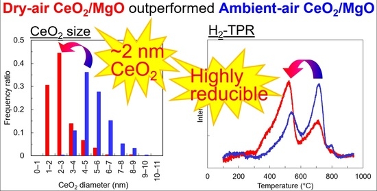
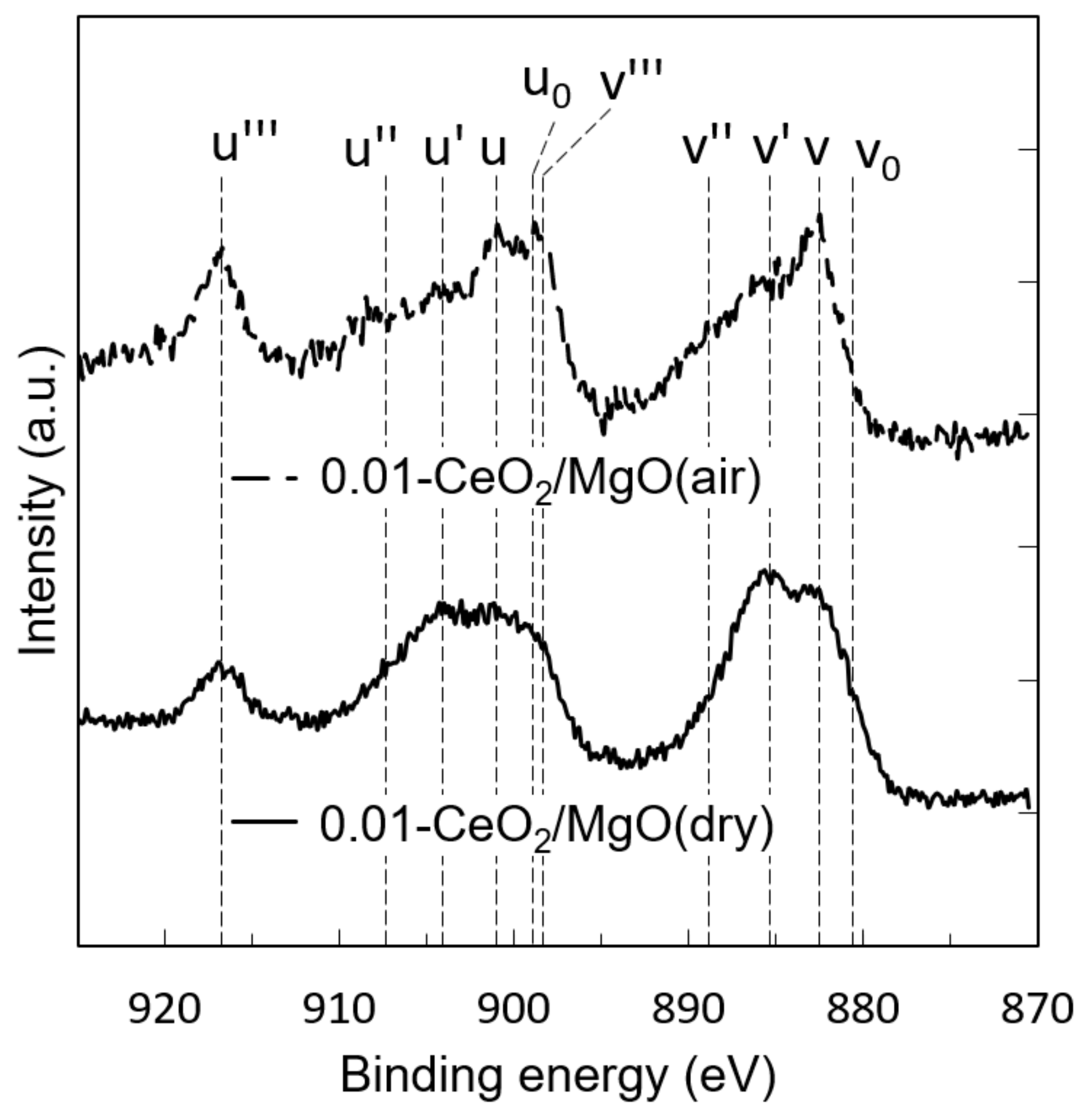
3.1. Characterization of the Catalysts

The content of CeO2 in the catalysts was calculated based on the results of ICP-OES. The obtained values were compared to the nominal values calculated from the amount of nitrates used. The nominal values and the experimental values are almost identical to each other (Table 1). This result suggests that all the catalysts were prepared at the nominal chemical composition as intended.
The crystallographic structure of the prepared catalysts was assessed by XRD. No peaks other than CeO2 and MgO were observed across all of the XRD patterns (Figure 1). The diffraction patterns of CeO2 were weaker for CeO2/MgO catalysts than for that of pure CeO2 because the content of CeO2 in CeO2/MgO was less than 20% in the mass ratio (Table 1). Further, no clear peak shift was observed for peaks of CeO2 and MgO, suggesting that the formation of the solid solution is small. These results are in good accordance with previous studies [31,34]. The amount of CeO2 and MgO dissolving with each other was negligible even at 1500 °C. On the other hand, a clear difference was observed between the samples in the peak shape. The broader peaks were observed for the samples prepared in the dry atmosphere than those prepared in the ambient air, suggesting the finer MgO and CeO2 particles of the samples prepared in the dry atmosphere.
The size of the CeO2 nanoparticles was also compared by TEM measurement (Figure 2). Small particles stuck on the large particles were assigned as CeO2 particles based on EDS-mapping results (Figure S1). Figure 3 shows the frequency distribution of the CeO2 diameter. The results are summarized in Table 1. Small CeO2 clusters (<3 nm), as well as larger nanoparticles (>3 nm), were observed in all the CeO2/MgO catalysts as reported by Tinoco et al. [32]. The average diameter of CeO2 increased as the content of CeO2 in the catalysts increased; 0.05-CeO2/MgO(air) and 0.05-CeO2/MgO(dry) contained larger CeO2 nanoparticles than 0.01-CeO2/MgO(air) and 0.01-CeO2/MgO(dry), respectively (Table 1). Meanwhile, smaller CeO2 nanoparticles were observed on the catalysts prepared under the dry atmosphere. The 0.01-CeO2/MgO(dry) sample contained 2.6-nm CeO2 on average, which is smaller than 5.3-nm CeO2 for 0.01-CeO2/MgO(air) (Table 1). The results of TEM were in good accordance with the results of XRD; the volume-weighted average of CeO2 nanoparticles was comparable for both TEM and XRD results (Table S2).
The difference in the size of the CeO2 nanoparticles was attributed to the difference in the BET area. As shown in Table 1, the BET area of MgO(dry) was approximately three times larger than that of MgO(air). MgO(dry) contained small cubic grains caused by the thermal decomposition of Mg(OH)2 (Figure S2) [42]. In contrast, larger octahedral grains were observed in MgO(air) instead of in cubic grains. This difference is ascribed to the water vapor contained in the ambient air. The water vapor accelerates the sintering of MgO of <5 nm in diameter [41,42,50]. Further, the stability of each facet of MgO depends on the humidity of the atmosphere; the {100} face is favored under the dry atmosphere, but the {111} face is under the humid atmosphere [38,51]. The morphological change of MgO due to the humidity caused the sintering of CeO2 nanoparticles during the calcination of the samples at 800 °C.
The precipitous drop in the BET surface areas of 0.01- and 0.05-CeO2/MgO(dry) compared to MgO(dry) was attributed to the condensed nitrate solutions formed during the drying process of the impregnation. During drying, the surface of MgO is covered by Mg(OH)2 since the acetone solution of Ce(NO3)3 contains water; Ce(NO3)3 6H2O was used as a precursor. Further, the acetone solution contains a small amount of water as an impurity [52]. Therefore, the equilibrium of Equation (3) is present during the drying process.
2Ce(NO3)3 + 3Mg(OH)2 ⇌ 2Ce(OH)3 + 3Mg(NO3)2
Mg(NO3)2 is soluble both in water and acetone [53,54]. Once the solution of Mg(NO3)2 formed, heterogeneous nucleation of Mg(NO3)2 and Ostwald ripening of MgO would proceed as reported for other oxides [55]. Therefore, the condensed nitrate solution would solve the MgO surface and increase its grain size, which reduced the surface area of MgO. This result suggests that it is possible to increase the surface area by further optimizing the combination of Ce precursors and solvents.

3.2. Mobility of Oxygen

The mobility of oxygen species on the catalysts was assessed by the TPR measurement (Figure 4). MgO had no peaks because it is irreducible under the measurement conditions (Figure S3). All the other catalysts showed peaks at ~500 and ~800 °C, but the relative intensity of these peaks varied depending on the catalyst. The former and latter peaks are ascribed to the surface capping oxygen and the bulk lattice oxygen of CeO2, respectively [1]. Notably, the intensity of the peaks at ~800 °C lowered as the CeO2 content decreased while the intensity of the peaks at ~500 °C remained comparable, suggesting that the low content of CeO2 led to finer CeO2 nanoparticles (Figure 4a,b). This result is in good agreement with the results of the TEM measurement (Table 1, Figure 2 and Figure 3). Further, the intensity of the peaks at ~800 °C was lower for CeO2/MgO(dry) than for CeO2/MgO(air) for both contents of CeO2. These results suggest that the surface capping oxygen was predominant for the finer CeO2 nanoparticles prepared under the dry atmosphere due to its larger surface area of CeO2 (Table 1). In particular, 0.01-CeO2/MgO(dry) had no peaks at ~800 °C, suggesting that both the surface capping oxygen and the lattice oxygen were removed at ~500 °C. This result is attributed to the fine CeO2 of d = 2.6 nm in 0.01-CeO2/MgO(dry) (Table 1). Such small CeO2 nanoparticles have high reducibility since their unit cell expanded [13,20]. The lattice oxygen of such CeO2 nanoparticles would diffuse ~1 nm from the center of the CeO2 nanoparticles to the surface under the reducing atmosphere.
In addition to the intensity of the reduction peak at ~500 °C, the shape of the peak also changed depending on the preparation condition; a small shoulder appeared at ~350 °C for the samples prepared under dry conditions. This low-temperature peak was attributed to the size-dependent orientation of CeO2 nanoparticles on the MgO surface. Reportedly, the crystallographic orientation of CeO2 nanoparticles varies depending on the size of CeO2; CeO2 of 1–3 nm in diameter faces its {111} surface to the {111} surface of MgO, but CeO2 of 10–20 nm in diameter faces its {100} surface to the {111} surface of MgO [32]. These studies suggest that preferential faceting of CeO2 nanoparticles depends on the size of CeO2. Further, the reducibility of the CeO2 surface strongly depends on their faceting [23]; the reduction peak position shifted from ~500 °C for conventional CeO2 to ~300 °C for nanorod CeO2. Therefore, we considered that the reducibility of the surface capping oxygen was modulated by the difference in the faceting of CeO2 nanoparticles caused by the size variation.
Redox properties of the catalysts were further assessed by TPO using CO2 as an oxidant. The catalysts were reduced in a 5%H2/Ar flow at 550 °C before the TPO measurements. As shown in Figure 5, the formation of CO starts at ~350 °C on all the catalysts. Further, the peak intensity is ~1.5 times higher on 0.05-CeO2/MgO(dry) compared to those on 0.05-CeO2/MgO(air) and pure CeO2. These results are consistent with the H2-TPR (Figure 4b); the reduction peak at ~500 °C on 0.05-CeO2/MgO(dry) is larger than those of the other catalysts. CO2 refilled the oxygen vacancies on the surface that formed during the reduction in an H2 flow. This result also demonstrated the improved oxygen mobility of 0.05-CeO2/MgO(dry) than those of 0.05-CeO2/MgO(air) and pure CeO2. Further, the results shown in Figure 4 and Figure 5 suggest that CeO2/MgO(dry) works as a catalyst for chemical looping combustion (CLC) [6,7,8,9]. The CLC proceeds as a two-step reaction; the catalyst is subjected to reducing conditions and then re-oxidized by CO2 or H2O to produce CO or H2, which is identical to the reaction in Figure 5.
XPS measurement was also performed on 0.01-CeO2/MgO(air) and 0.01-CeO2/MgO(dry) to clarify the difference of CeO2 nanoparticles caused by the preparation condition. As shown in Figure 6, a distinct difference was observed in the spectra. There were ten peaks derived from Ce4+ and Ce3+. The peaks annotated by v, v’’, v’’’, u, u’’, and u’’’ were attributed to Ce4+. Meanwhile, v0, v’, u0, and u’ were due to Ce3+. The binding energies of each peak are described in the caption of Figure 6. Intense peaks of Ce3+ denoted by v’ and u’ were observed for 0.01-CeO2/MgO(dry). Further, the relative intensity of the Ce3d3/2 peak denoted by u’’’ was lower for 0.01-CeO2/MgO(dry) than for 0.01-CeO2/MgO(air), suggesting the presence of Ce3+ in 0.01-CeO2/MgO(dry) [45,46]. Reportedly, the relative intensity of u’’’ is not linearly correlated to the content of Ce3+, but such a clear difference in the intensity of u’’’ suggests that more than 30% of Ce in 0.01-CeO2/MgO(dry) was Ce3+ [46,58]. This difference in the Ce3+ content is ascribed to the size of CeO2. Several studies reported that CeO2 nanoparticles smaller than 3 nm in diameter were relaxed in their crystal structure [13,19]; such small CeO2 nanoparticles were vulnerable to in situ reductions during the exposure to X-ray under vacuum. As shown in Figure 3, 0.01-CeO2/MgO(dry) contained a lot of CeO2 nanoparticles smaller than 3 nm, which would be reduced during the XPS measurement. Such high reducibility of 0.01-CeO2/MgO(dry) matched well with the results of H2-TPR (Figure 4). 0.01-CeO2/MgO(dry) was reduced at a lower temperature than 0.01-CeO2/MgO(air). Here, it is noteworthy that the effect of precursors on the valence of Ce was minor because both samples were prepared using the same precursor [13].

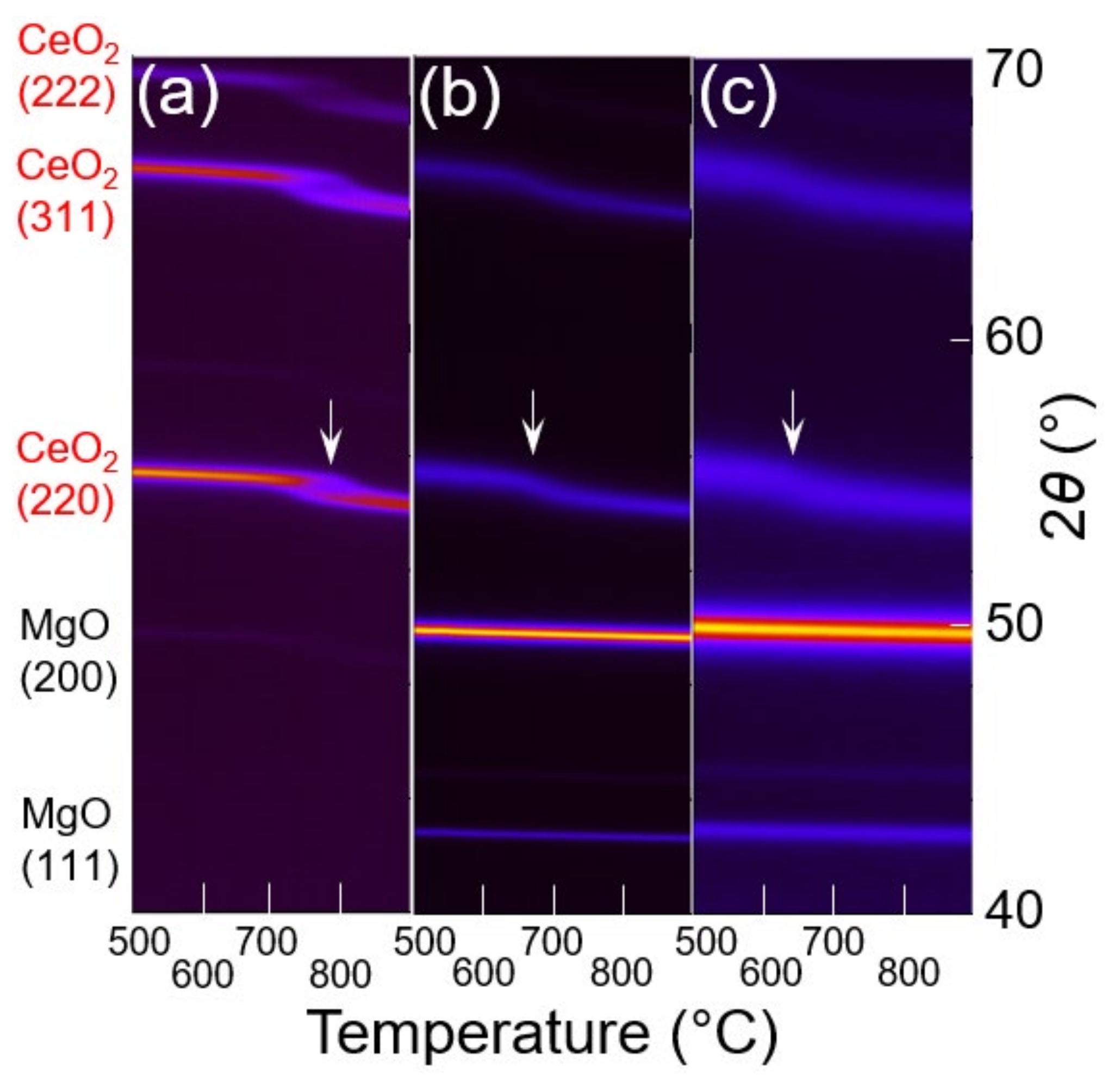
3.3. In Situ XRD Study under the Reducing Atmosphere

In situ XRD was performed to visualize the structural variation of CeO2 nanoparticles during the reduction. Instead of 0.01-CeO2/MgO, 0.05-CeO2/MgO(air) and 0.05-CeO2/MgO(dry) were used to increase the peak intensity to perform further analyses. The measurements were performed under the same condition as that of H2-TPR, but an N2 balance was used as a balance instead of Ar. CeO2 was also subjected to the same measurement as a reference. The results are shown in Figure 7. Only the peaks of CeO2 and MgO were observed in the patterns since the phase change from CeO2 to Ce2O3 is slow. The absence of Ce2O3 was consistent with the previous studies [1,59,60]. As shown in the patterns of CeO2/MgO (Figure 7b,c), the peaks of MgO linearly shifted to lower 2θ as the temperature increased, suggesting a continuous thermal expansion of MgO crystals. The peaks of CeO2 also shifted to the same direction; however, the peaks showed the inflection points at ~650 °C (Figure 7b,c). This implies that structural relaxation was caused by the removal of lattice oxygen of the CeO2 nanoparticles. Additionally, CeO2 in both CeO2/MgO(air) and CeO2/MgO(dry) underwent structural change at lower temperatures than pure CeO2 (Figure 7a–c). The inflection point appeared at ~800 °C for pure CeO2 (Figure 7a). This result suggests that CeO2 in CeO2/MgO was reduced faster than pure CeO2, which is in good agreement with H2-TPR (Figure 4).
Another difference between the CeO2/MgO and the pure CeO2 was observed in the shape of the diffraction patterns of CeO2 (Figure 7a–c). Notably, the splitting of diffraction patterns was observed for pure CeO2 around 2θ = ~55° and ~65° at ~750 °C (Figure 6a and Figure S4). This result suggests that the reduction proceeded heterogeneously in CeO2 grains. As shown in Figure 4, H2-TPR of pure CeO2 detected a long tailing to a high temperature at >800 °C. Such tailing means that the reduction of pure CeO2 was limited by the diffusion of oxygen in CeO2 [61,62,63]. Such diffusion-controlled reduction would render the outer side of CeO2 particles more reduced than the inner part of them. In contrast, such splitting was not observed for CeO2/MgO catalysts. The reduction of CeO2 nanoparticles in CeO2/MgO proceeded more homogeneously than pure CeO2 due to the small size of CeO2 nanoparticles.
The variation of unit cell parameter a0 of CeO2 was calculated assuming that the structural change of CeO2 nanoparticles was isotropic. The calculated values of a0 were normalized by the values at 200 °C to see the variation depending on the temperature. As shown in Figure 8, the unit cell parameter a0 increased at a lower temperature for 0.05-CeO2/MgO(dry) than for 0.05-CeO2/MgO(air). The first derivative of the unit cell parameter held a peak at 640 °C and 680 °C for 0.05-CeO2/MgO(dry) and 0.05-CeO2/MgO(air), respectively (Figure S5). This difference was ascribed to the smaller size of CeO2 in 0.05-CeO2/MgO(dry). As confirmed by H2-TPR (Figure 4), 0.05-CeO2/MgO(dry) was reduced at a lower temperature than 0.05-CeO2/MgO(air) due to the higher dispersion of CeO2 (Figure 3). The faster removal of the oxygen from the lattice led to the structural change at a lower temperature. In addition, structural relaxation proceeds more easily as the size of CeO2 decreases [13,17,19]. The results of in situ XRD also demonstrated that 0.05-CeO2/MgO(dry) was reduced at lower temperatures than 0.05-CeO2/MgO(air).

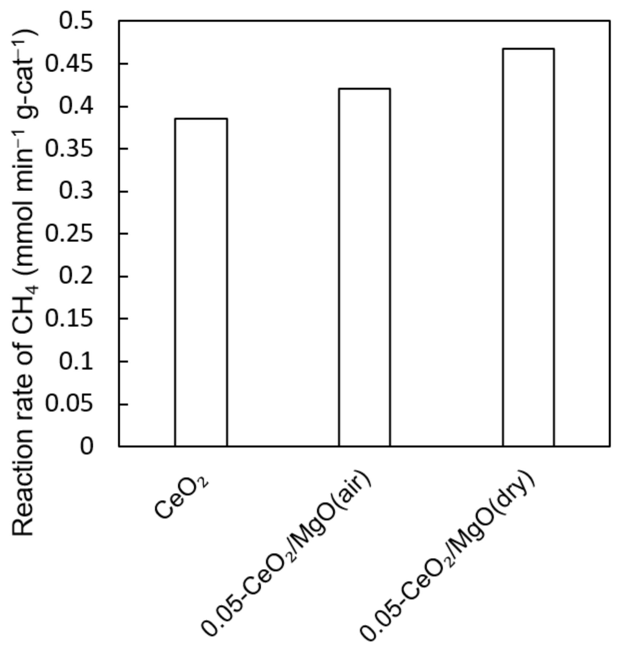
3.4. Dry Reforming Reaction

As shown in previous sections, CeO2 nanoparticles in 0.05-CeO2/MgO(dry) were smaller than those in 0.05-CeO2/MgO(air). Such small CeO2 nanoparticles led to the high mobility of the lattice oxygen. In this section, the difference of the catalysts was demonstrated via a dry reforming reaction, in which the catalysts were exposed to dry reductive gas at high temperatures. Figure 9 shows the average reaction rate of CH4 throughout the reaction. The time course profile of the CH4 conversion rate is also shown in Figure S6. All the catalysts remained white or yellow after the reaction, suggesting the absence of carbon deposition. Both 0.05-CeO2/MgO(air) and 0.05-CeO2/MgO(dry) outperformed pure CeO2 despite their low content of CeO2, i.e., 18.3 wt%. Further, a higher conversion was attained over 0.05-CeO2/MgO(dry) than over 0.05-CeO2/MgO(air). These differences were ascribed to the dispersion of CeO2 nanoparticles. The average diameter of pure CeO2 was 61.6 nm while those of 0.05-CeO2/MgO(air) and 0.05-CeO2/MgO(dry) were 6.9 nm and 4.5 nm, respectively (Table 1). The finer CeO2 nanoparticles led to the higher surface area of CeO2, resulting in the higher catalytic activity. In addition, 0.05-CeO2/MgO(air) exhibited higher activity than pure CeO2 although the area of CeO2 in 0.05-CeO2/MgO(air), 12.5 m2/g, was smaller than that of pure CeO2, 13.5 m2/g (Table 1). Our previous study also suggests that MgO promotes CO2 supply to the CeO2 surface due to the strong basicity of the MgO [36]. Such interaction would also contribute to the higher catalytic activity of CeO2/MgO.
The selectivity of the reaction is also illustrated in Figure S7 as the time course profile of the outlet gas composition. All the reaction proceeds under the reaction condition of a low conversion rate of CH4, ~4%. Due to the low conversion rate, the selectivity of H2 against CO was as low as 0.1–0.2 (Figure S7). Notably, the average value of H2/CO throughout the 6-h reaction was slightly smaller for pure CeO2, 0.11, than 0.05-CeO2/MgO(air), 0.18, and 0.05-CeO2/MgO(dry), 0.17. The origin of this difference is uncertain, but we attributed it to the CH4 conversion rate and reducibility of CeO2. As shown in Figure 9, the CH4 conversion rate over the pure CeO2 is lower than those over 0.05-CeO2/MgO. This means the total supply of H2 is less over CeO2 than over 0.05-CeO2/MgO, causing the difference in the H2/CO ratio. Another possible origin of the difference is the reducibility of CeO2. H2-TPR demonstrated that reduction of pure CeO2 did not complete even at 800 °C (Figure 4). This result suggests that the pure CeO2 continued to be reduced by the product H2 during the reaction. Such a reaction would lead to a lower H2/CO ratio due to the consumption of H2.
The temporal variation of the CH4 conversion rate also depended on the catalysts. The pure CeO2 was deactivated rapidly within the initial two hours but then gradually (Figure S6). On the contrary, such an initial rapid drop of the CH4 conversion rate was not observed for 0.05-CeO2/MgO(air) and 0.05-CeO2/MgO(dry). This difference in the initial behavior was attributed to the stoichiometry of the CeO2 surface influenced by the diffusion of oxygen in the CeO2 particles. As shown in Figure 4, the reduction of pure CeO2 at 800 °C was diffusion controlled. The reduction did not complete even at 900 °C. This result suggests that it takes a long time to reach the equilibrium in the oxygen content of the pure CeO2 during the reaction. Contrary, the reduction of 0.05-CeO2/MgO(air) and 0.05-CeO2/MgO(dry) was almost completed at 800 °C in H2-TPR (Figure 4), suggesting that it takes a short time to reach the equilibrium in the oxygen content of CeO2/MgO during the reaction. Therefore, there would be fewer oxygen vacancies on the surface of pure CeO2 than on CeO2 nanoparticles in CeO2/MgO. Such fewer oxygen vacancies of the pure CeO2 would improve the initial activity because previous studies reported that the C-H activation energy on CeO2 decreased as the number of oxygen vacancies decreased [64,65].
Notably, 0.05-CeO2/MgO(air) exhibited steady catalytic activity throughout the 6-h reaction, but 0.05-CeO2/MgO(dry) was gradually deactivated (Figure S6). The gradual deactivation of 0.05-CeO2/MgO(dry) was attributed to the gradual sintering of CeO2 nanoparticles caused by the moisture content in the gas. Dry reforming produces H2O along with H2 and CO. Although the concentration of water in the product gas was lower than that of ambient air (Table S3), 0.05-CeO2/MgO(dry) was exposed to the water vapor at 800 °C during the reaction, causing the structural change of 0.05-CeO2/MgO(dry). On the contrary, 0.05-CeO2/MgO(air) was already heated at 800 °C in the ambient air containing ~3 vol% of H2O before the reaction (Table S3). Therefore, the byproduct H2O in the product gas affected 0.05-CeO2/MgO(dry) more than 0.05-CeO2/MgO(air).
As discussed above, 0.05-CeO2/MgO(dry) gradually deactivated during the dry reforming reaction while 0.05-CeO2/MgO(air) exhibited stable activity. This difference in the behavior of 0.05-CeO2/MgO(air) and 0.05-CeO2/MgO(dry) suggests that the preparation of catalysts under the dry atmosphere is effective only for the reactions in the absence of H2O. Solar-thermochemical reaction is an example of such reactions [7]. The solar-thermochemical reaction proceeds as a two-step reaction; the catalyst is subjected to high temperatures to be reduced thermodynamically and then re-oxidized by CO2 at low temperatures to produce CO. The CeO2/MgO(dry) would be suitable for the reaction since it demonstrated high stability and reducibility under dry conditions (Figure 4 and Figure 5).

4. Conclusions

This study demonstrated that stable CeO2 nanoparticles were deposited on MgO by the simple impregnation method. When CeO2/MgO was prepared under the dry atmosphere, the CeO2 nanoparticles remained ~3 nm in diameter even after being heated at 800 °C, which is much smaller than ~5 nm of CeO2/MgO prepared under ambient air. The difference was attributed to the higher surface area of the catalysts prepared under the dry atmosphere. H2-TPR, CO2-TPO, XPS, and in situ XRD showed that CeO2/MgO(dry) exhibited higher oxygen mobility than CeO2/MgO(air) due to the higher dispersion of CeO2 nanoparticles. The higher catalytic activity of CeO2/MgO(dry) than CeO2/MgO(air) was also demonstrated by the dry reforming reaction.

Supplementary Materials

The following are available online at https://www.mdpi.com/article/10.3390/en14237922/s1, Table S1: Chemical composition of CeO2 estimated by X-ray fluorescence, Figure S1: Scanning Transmission Electron Microscope images (a,d) and corresponding energy dispersive X-ray spectroscopy mapping of Ce Lα (b,e) and Mg Kα (c,f) for Ce0.01Mg0.99O1.01 (a–c), Ce0.05Mg0.95O1.05 (d–f), Table S2: Volume-weighted average diameter of CeO2 nanoparticles estimated from TEM and XRD results, Figure S2: TEM images of (above) MgO(air) and (bottom) MgO(dry), Figure S3: H2-TPR profile of MgO(air), Figure S4: XRD patterns of CeO2 during in situ XRD measurement, Figure S5: The first derivative of a0/a0 shown in Figure 8 of the main manuscript, Figure S6: Time course profiles of the CH4 conversion rates during dry reforming reactions, Figure S7. Time course profiles of the outlet gas composition during dry reforming reactions, Table S3: Compositions of the inlet and outlet gases during the dry reforming reaction.

Author Contributions

Conceptualization, K.T.; methodology, K.T.; validation, K.T. and R.M.; formal analysis, K.T. and R.M.; investigation, K.T. and R.M.; resources, K.T.; data curation, K.T.; writing—original draft preparation, K.T.; writing—review and editing, K.T.; visualization, K.T.; supervision, K.T.; project administration, K.T.; funding acquisition, K.T. All authors have read and agreed to the published version of the manuscript.

Funding

This research received no external funding.

Acknowledgments

I would like to show my appreciation to Hiroshima and Tani from Nippon Steel Corporation for the maintenance and troubleshooting of TEM measurements.

Conflicts of Interest

The authors declare no conflict of interest.

References

  1. Trovarelli, A. Catalytic properties of ceria and CeO2-Containing materials. Catal. Rev.-Sci. Eng. 1996, 38, 439–520. [Google Scholar] [CrossRef]
  2. Yang, X.; Da, J.; Yu, H.; Wang, H. Characterization and performance evaluation of Ni-based catalysts with Ce promoter for methane and hydrocarbons steam reforming process. Fuel 2016, 179, 353–361. [Google Scholar] [CrossRef]
  3. Savuto, E.; Navarro, R.M.; Mota, N.; Di Carlo, A.; Bocci, E.; Carlini, M.; Fierro, J.L.G. Steam reforming of tar model compounds over Ni/Mayenite catalysts: Effect of Ce addition. Fuel 2018, 224, 676–686. [Google Scholar] [CrossRef]
  4. Gac, W.; Zawadzki, W.; Rotko, M.; Słowik, G.; Greluk, M. CO2 Methanation in the Presence of Ce-Promoted Alumina Supported Nickel Catalysts: H2S Deactivation Studies. Top. Catal. 2019, 62, 524–534. [Google Scholar] [CrossRef] [Green Version]
  5. Yeo, T.Y.; Ashok, J.; Kawi, S. Recent developments in sulphur-resilient catalytic systems for syngas production. Renew. Sustain. Energy Rev. 2019, 100, 52–70. [Google Scholar] [CrossRef]
  6. Nair, M.M.; Abanades, S. Tailoring Hybrid Nonstoichiometric Ceria Redox Cycle for Combined Solar Methane Reforming and Thermochemical Conversion of H2O/CO2. Energy Fuels 2016, 30, 6050–6058. [Google Scholar] [CrossRef]
  7. Arifin, D.; Weimer, A.W. Kinetics and mechanism of solar-thermochemical H2 and CO production by oxidation of reduced CeO2. Sol. Energy 2018, 160, 178–185. [Google Scholar] [CrossRef]
  8. Zheng, Y.; Li, K.; Wang, H.; Tian, D.; Wang, Y.; Zhu, X.; Wei, Y.; Zheng, M.; Luo, Y. Designed oxygen carriers from macroporous LaFeO3 supported CeO2 for chemical-looping reforming of methane. Appl. Catal. B Environ. 2017, 202, 51–63. [Google Scholar] [CrossRef]
  9. Galvita, V.V.; Poelman, H.; Bliznuk, V.; Detavernier, C.; Marin, G.B. CeO2-Modified Fe2O3 for CO2 Utilization via Chemical Looping. Ind. Eng. Chem. Res. 2013, 52, 8416–8426. [Google Scholar] [CrossRef]
  10. Zaimes, G.G.; Hubler, B.J.; Wang, S.; Khanna, V. Environmental life cycle perspective on rare earth oxide production. ACS Sustain. Chem. Eng. 2015, 3, 237–244. [Google Scholar] [CrossRef]
  11. Haque, N.; Hughes, A.; Lim, S.; Vernon, C. Rare earth elements: Overview of mining, mineralogy, uses, sustainability and environmental impact. Resources 2014, 3, 614–635. [Google Scholar] [CrossRef] [Green Version]
  12. Lin, Y.; Wu, Z.; Wen, J.; Poeppelmeier, K.R.; Marks, L.D. Imaging the atomic surface structures of CeO2 nanoparticles. Nano Lett. 2014, 14, 191–196. [Google Scholar] [CrossRef]
  13. Paun, C.; Safonova, O.V.; Szlachetko, J.; Abdala, P.M.; Nachtegaal, M.; Sa, J.; Kleymenov, E.; Cervellino, A.; Krumeich, F.; Van Bokhoven, J.A. Polyhedral CeO2 nanoparticles: Size-dependent geometrical and electronic structure. J. Phys. Chem. C 2012, 116, 7312–7317. [Google Scholar] [CrossRef]
  14. Matei-Rutkovska, F.; Postole, G.; Rotaru, C.G.; Florea, M.; Pârvulescu, V.I.; Gelin, P. Synthesis of ceria nanopowders by microwave-assisted hydrothermal method for dry reforming of methane. Int. J. Hydrog. Energy 2016, 41, 2512–2525. [Google Scholar] [CrossRef]
  15. Laosiripojana, N.; Charojrochkul, S.; Kim-lohsoontorn, P.; Assabumrungrat, S. Role and advantages of H2S in catalytic steam reforming over nanoscale CeO2 -based catalysts. J. Catal. 2010, 276, 6–15. [Google Scholar] [CrossRef]
  16. Wu, Z.; Zhang, J.; Benfield, R.E.; Ding, Y.; Grandjean, D.; Zhang, Z.; Ju, X. Structure and Chemical Transformation in Cerium Oxide Nanoparticles Coated by Surfactant Cetyltrimethylammonium Bromide (CTAB): An X-ray Absorption Spectroscopic Study. J. Phys. Chem. B 2002, 106, 4569–4577. [Google Scholar] [CrossRef] [Green Version]
  17. Zhang, F.; Chan, S.W.; Spanier, J.E.; Apak, E.; Jin, Q.; Robinson, R.D.; Herman, I.P. Cerium oxide nanoparticles: Size-selective formation and structure analysis. Appl. Phys. Lett. 2002, 80, 127–129. [Google Scholar] [CrossRef] [Green Version]
  18. Natile, M.M.; Boccaletti, G.; Glisenti, A. Properties and reactivity of nanostructured CeO2 powders: Comparison among two synthesis procedures. Chem. Mater. 2005, 17, 6272–6286. [Google Scholar] [CrossRef]
  19. Spanier, J.E.; Robinson, R.D.; Zhang, F.; Chan, S.; Herman, I.P. Size-dependent properties of CeO2-y nanoparticles as studied by Raman scattering. Phys. Rev. B 2001, 64, 245407. [Google Scholar] [CrossRef] [Green Version]
  20. Hailstone, R.K.; DiFrancesco, A.G.; Leong, J.G.; Allston, T.D.; Reed, K.J. A study of lattice expansion in CeO2 Nanoparticles by Transmission Electron Microscopy. J. Phys. Chem. C 2009, 113, 15155–15159. [Google Scholar] [CrossRef]
  21. Han, W.Q.; Wen, W.; Hanson, J.C.; Teng, X.; Marinkovic, N.; Rodriguez, J.A. One-dimensional ceria as catalyst for the low-temperature water-gas shift reaction. J. Phys. Chem. C 2009, 113, 21949–21955. [Google Scholar] [CrossRef]
  22. Zhang, J.; Kumagai, H.; Yamamura, K.; Ohara, S.; Takami, S.; Morikawa, A.; Shinjoh, H.; Kaneko, K.; Adschiri, T.; Suda, A. Extra-Low-Temperature Oxygen Storage Capacity of CeO2 Nanocrystals with Cubic Facets. Nano Lett. 2011, 11, 361–364. [Google Scholar] [CrossRef] [PubMed]
  23. Aneggi, E.; Wiater, D.; de Leitenburg, C.; Llorca, J.; Trovarelli, A. Shape-Dependent Activity of Ceria in Soot Combustion. ACS Catal. 2014, 4, 172–181. [Google Scholar] [CrossRef]
  24. Liu, Z.; Sorrell, C.C.; Koshy, P.; Hart, J.N. DFT Study of Methanol Adsorption on Defect-Free CeO2 Low-Index Surfaces. ChemPhysChem 2019, 20, 2074–2081. [Google Scholar] [CrossRef]
  25. Branda, M.M.; Ferullo, R.M.; Causá, M.; Illas, F. Relative stabilities of low index and stepped CeO2 surfaces from hybrid and GGA + U implementations of density functional theory. J. Phys. Chem. C 2011, 115, 3716–3721. [Google Scholar] [CrossRef]
  26. Damyanova, S.; Bueno, J.M.C. Effect of CeO2 loading on the surface and catalytic behaviors of CeO2-Al2O3-supported Pt catalysts. Appl. Catal. A Gen. 2003, 253, 135–150. [Google Scholar] [CrossRef]
  27. Reddy, B.M.; Rao, K.N.; Reddy, G.K.; Khan, A.; Park, S.E. Structural characterization and oxidehydrogenation activity of CeO 2/Al2O3 and V2O5/ CeO2ZAl2O3 catalysts. J. Phys. Chem. C 2007, 111, 18751–18758. [Google Scholar] [CrossRef]
  28. Shyu, J.Z.; Weber, W.H.; Gandhi, H.S. Surface characterization of alumina-supported ceria. J. Phys. Chem. 1988, 92, 4964–4970. [Google Scholar] [CrossRef]
  29. Beniya, A.; Isomura, N.; Hirata, H.; Watanabe, Y. Morphology and chemical states of size-selected Pt n clusters on an aluminium oxide film on NiAl(110). Phys. Chem. Chem. Phys. 2014, 16, 26485–26492. [Google Scholar] [CrossRef] [PubMed] [Green Version]
  30. Ma, Y.; Ma, Y.; Li, J.; Li, Q.; Hu, X.; Ye, Z.; Wu, X.Y.; Buckley, C.E.; Dong, D. CeO2-promotion of NiAl2O4 reduction via CeAlO3 formation for efficient methane reforming. J. Energy Inst. 2020, 93, 991–999. [Google Scholar] [CrossRef]
  31. Nataliya Bochvar, N.; Liberov, Y.; Fabrichnaya, O.; MSIT®. Ce-Mg-O Ternary Phase Diagram Evaluation. Available online: https://materials.springer.com/msi/docs/sm_msi_r_10_012253_02 (accessed on 26 November 2020).
  32. Tinoco, M.; Sanchez, J.J.; Yeste, M.P.; Lopez-Haro, M.; Trasobares, S.; Hungria, A.B.; Bayle-guillemaud, P.; Blanco, G.; Pintado, J.M.; Calvino, J.J. Low-Lanthanide-Content CeO2/MgO Catalysts with Outstandingly Stable Oxygen Storage Capacities: An In-Depth Structural Characterization by Advanced STEM Techniques. ChemCatChem 2015, 7, 3763–3778. [Google Scholar] [CrossRef]
  33. Pérez Casero, R.; Gómez San Román, R.; Perrière, J.; Laurent, A.; Seiler, W.; Gergaud, P.; Keller, D. Epitaxial growth of CeO2 on MgO by pulsed laser deposition. Appl. Surf. Sci. 1997, 109–110, 341–344. [Google Scholar] [CrossRef]
  34. Paunović, V.; Zichittella, G.; Mitchell, S.; Hauert, R.; Pérez-Ramírez, J. Selective Methane Oxybromination over Nanostructured Ceria Catalysts. ACS Catal. 2018, 8, 291–303. [Google Scholar] [CrossRef]
  35. Plewa, J.; Steindor, J. Kinetics of reduction of magnesium sulfate by carbon oxide. J. Therm. Anal. 1987, 32, 1809–1820. [Google Scholar] [CrossRef]
  36. Taira, K. Dry reforming reactions of CH4 over CeO2/MgO catalysts at high concentrations of H2S. 2021, J. Cat. Under revision. J. Cat. Under revision.. 2021. [Google Scholar]
  37. Ferreira, V.J.; Tavares, P.; Figueiredo, J.L.; Faria, J.L. Effect of Mg, Ca, and Sr on CeO2 based catalysts for the oxidative coupling of methane: Investigation on the oxygen species responsible for catalytic performance. Ind. Eng. Chem. Res. 2012, 51, 10535–10541. [Google Scholar] [CrossRef]
  38. Geysermans, P.; Finocchi, F.; Goniakowski, J.; Hacquart, R.; Jupille, J. Combination of (100), (110) and (111) facets in MgO crystals shapes from dry to wet environment. Phys. Chem. Chem. Phys. 2009, 11, 2228–2233. [Google Scholar] [CrossRef] [PubMed]
  39. Holt, S.A.; Jones, C.F.; Watson, G.S.; Crossley, A.; Johnston, C. Surface modification of MgO substrates from aqueous exposure: An atomic force microscopy study. Thin Solid Film. 1997, 292, 96–102. [Google Scholar] [CrossRef]
  40. Eastman, P.F.; Culter, I.B. Effect of Water Vapor on Initial Sintering of Magnesia. J. Am. Ceram. Soc. 1966, 49, 526–530. [Google Scholar] [CrossRef]
  41. Ito, T.; Fujita, M.; Watanabe, M.; Tokuda, T. The initial sintering of alkaline earth oxides in water vapor and hydrogen gas. Bull. Cemical Soc. Japan 1981, 54, 2412–2419. [Google Scholar] [CrossRef] [Green Version]
  42. Green, J. Calcination of precipitated Mg(OH)2 to active MgO in the production of refractory and chemical grade MgO. J. Mater. Sci. 1983, 18, 637–651. [Google Scholar] [CrossRef]
  43. Peng, C.; Zhang, Z. Nitrate–citrate combustion synthesis of Ce1−xGdxO2−x/2 powder and its characterization. Ceram. Int. 2007, 33, 1133–1136. [Google Scholar] [CrossRef]
  44. Taira, K.; Nakao, K.; Suzuki, K.; Einaga, H. SOx tolerant Pt/TiO2 catalysts for CO oxidation and the effect of TiO2 supports on catalytic activity. Environ. Sci. Technol. 2016, 50, 9773–9780. [Google Scholar] [CrossRef] [PubMed]
  45. Burroughs, P.; Hamnett, A.; Orchard, A.F.; Thornton, G. Satellite structure in the X-ray photoelectron spectra of some binary and mixed oxides of lanthanum and cerium. J. Chem. Soc. Dalt. Trans. 1976, 1686. [Google Scholar] [CrossRef]
  46. Romeo, M.; Bak, K.; El Fallah, J.; Le Normand, F.; Hilaire, L. XPS Study of the reduction of cerium dioxide. Surf. Interface Anal. 1993, 20, 508–512. [Google Scholar] [CrossRef]
  47. National Institute of Standards and Technology. NIST X-Ray Photoelectron Spectroscopy Database; NIST Standard Reference Database Number 20; National Institute of Standards and Technology: Gaithersburg, MD, USA, 2000. [Google Scholar] [CrossRef]
  48. Della Mea, G.B.; Matte, L.P.; Thill, A.S.; Lobato, F.O.; Benvenutti, E.V.; Arenas, L.T.; Jürgensen, A.; Hergenröder, R.; Poletto, F.; Bernardi, F. Tuning the oxygen vacancy population of cerium oxide (CeO2−x, 0 <x <0.5) nanoparticles. Appl. Surf. Sci. 2017, 422, 1102–1112. [Google Scholar] [CrossRef]
  49. Taira, K.; Sugiyama, T.; Einaga, H.; Nakao, K.; Suzuki, K. Promoting effect of 2000 ppm H2S on the dry reforming reaction of CH4 over pure CeO2, and in situ observation of the behavior of sulfur during the reaction. J. Catal. 2020, 389, 611–622. [Google Scholar] [CrossRef]
  50. Beruto, D.; Botter, R.; Searcy, A.W. H2O-Catalyzed Sintering of ~2-nm-Cross-Section Particles of MgO. J. Am. Ceram. Soc. 1987, 70, 155–159. [Google Scholar] [CrossRef]
  51. Cadigan, C.A.; Corpuz, A.R.; Lin, F.; Caskey, C.M.; Finch, K.B.H.; Wang, X.; Richards, R.M. Nanoscale (111) faceted rock-salt metal oxides in catalysis. Catal. Sci. Technol. 2013, 3, 900–911. [Google Scholar] [CrossRef]
  52. Gottlieb, H.E.; Kotlyar, V.; Nudelman, A. NMR chemical shifts of common laboratory solvents as trace impurities. J. Org. Chem. 1997, 3263, 7512–7515. [Google Scholar] [CrossRef] [PubMed]
  53. Sangwal, K. Mechanism of dissolution of MgO crystals in acids. J. Mater. Sci. 1980, 15, 237–246. [Google Scholar] [CrossRef]
  54. Filley, J.; Ibrahim, M.A.; Nimlos, M.R.; Watt, A.S.; Blake, D.M. Magnesium and calcium chelation by a bis-spiropyran. J. Photochem. Photobiol. A Chem. 1998, 117, 193–198. [Google Scholar] [CrossRef]
  55. Hu, Y.; Lee, B.; Bell, C.; Jun, Y.-S. Environmentally Abundant Anions Influence the Nucleation, Growth, Ostwald Ripening, and Aggregation of Hydrous Fe(III) Oxides. Langmuir 2012, 28, 7737–7746. [Google Scholar] [CrossRef]
  56. Karen, P.; Kjekshus, A.; Huang, Q.; Karen, V.L. The crystal structure of magnesium dicarbide. J. Alloys Compd. 1999, 282, 72–75. [Google Scholar] [CrossRef]
  57. McBride, J.R.; Hass, K.C.; Poindexter, B.D.; Weber, W.H. Raman and X-ray studies of Ce1-xRExO2-y, where RE=La, Pr, Nd, Eu, Gd, and Tb. J. Appl. Phys. 1994, 76, 2435–2441. [Google Scholar] [CrossRef]
  58. Holgado, J.P.; Alvarez, R.; Munuera, G. Study of CeO2 XPS spectra by factor analysis: Reduction of CeO2. Appl. Surf. Sci. 2000, 161, 301–315. [Google Scholar] [CrossRef]
  59. Galvita, V.V.; Poelman, H.; Rampelberg, G.; De Schutter, B.; Detavernier, C.; Marin, G.B. Structural and kinetic study of the reduction of CuO-CeO2/Al2O3 by time-resolved X-ray diffraction. Catal. Lett. 2012, 142, 959–968. [Google Scholar] [CrossRef]
  60. Perrichon, V.; Laachir, A.; Bergeret, G.; Fréty, R.; Tournayan, L.; Touret, O. Reduction of cerias with different textures by hydrogen and their reoxidation by oxygen. J. Chem. Soc. Faraday Trans. 1994, 90, 773–781. [Google Scholar] [CrossRef]
  61. Stan, M.; Zhu, Y.T.; Jiang, H.; Butt, D.P. Kinetics of oxygen removal from ceria. J. Appl. Phys. 2004, 95, 3358–3361. [Google Scholar] [CrossRef]
  62. Al-Madfaa, H.A.; Khader, M.M. Reduction kinetics of ceria surface by hydrogen. Mater. Chem. Phys. 2004, 86, 180–188. [Google Scholar] [CrossRef]
  63. Goguet, A.; Meunier, F.C.; Tibiletti, D.; Breen, J.P.; Burch, R. Spectrokinetic Investigation of Reverse Water-Gas-Shift Reaction Intermediates over a Pt/CeO2 Catalyst. J. Phys. Chem. B 2004, 108, 20240–20246. [Google Scholar] [CrossRef] [Green Version]
  64. Warren, K.J.; Scheffe, J.R. Role of Surface Oxygen Vacancy Concentration on the Dissociation of Methane over Nonstoichiometric Ceria. J. Phys. Chem. C 2019, 123, 13208–13218. [Google Scholar] [CrossRef]
  65. Kumar, G.; Lau, S.L.J.; Krcha, M.D.; Janik, M.J. Correlation of Methane Activation and Oxide Catalyst Reducibility and Its Implications for Oxidative Coupling. ACS Catal. 2016, 6, 1812–1821. [Google Scholar] [CrossRef]
Figure 1. XRD patterns of (a) 0.01-CeO2/MgO and (b) 0.05-CeO2/MgO catalysts compared to that of pure CeO2. A Cu X-ray source and an Ni filter were used. MgO and CeO2 patterns were assigned based on the references [56,57].
Energies 14 07922 g001
Figure 2. TEM images of (a) 0.01-CeO2/MgO(air), (b) 0.05-CeO2/MgO(air), (c) 0.01-CeO2/MgO(dry), (d) 0.05-CeO2/MgO(dry), and (e) CeO2. STEM-EDS of the samples are shown in Figure S1.
Energies 14 07922 g002
Figure 3. Frequency distribution of the CeO2 diameter in (a) 0.01-CeO2/MgO, and (b) 0.05-CeO2/MgO.
Energies 14 07922 g003
Figure 4. H2-TPR profiles of (a) 0.01-CeO2/MgO and (b) 0.05-CeO2/MgO catalysts compared to that of pure CeO2.
Energies 14 07922 g004
Figure 5. CO2-TPO profiles of the reduced catalysts. The catalysts were heated at 20 °C/min in a 5% CO2/Ar flow after the reduction at 550 °C in a 5% H2/Ar flow.
Energies 14 07922 g005
Figure 6. XPS spectra of 0.01-CeO2/MgO(air) and 0.01-CeO2/MgO(dry). The peak positions of v0, v, v’, v’’, v’’’, u0, u, u’, u’’, and u’’’ are 880.60, 882.60, 885.45, 888.85, 898.40, 898.90, 901.05, 904.05, 907.45, and 916.70 eV, respectively. The binding energies of all the peaks are identical to the values of the reference [46].
Energies 14 07922 g006
Figure 7. In situ XRD patterns of (a) CeO2, (b) 0.05-CeO2/MgO(air), and (c) 0.05-CeO2/MgO(dry). A Co X-ray source and an Fe filter were used for the measurements. White arrows indicate the inflection points observed on the (220) peaks of CeO2. The unassigned weak peaks were attributed to the diffraction of Co K-β.
Energies 14 07922 g007
Figure 8. Unit cell parameter a0 of CeO2 nanoparticles of 0.05-CeO2/MgO(air) and 0.05-CeO2/MgO(dry) calculated from in situ XRD measurement. The vertical axis is normalized by the value of a0 at 200 °C.
Energies 14 07922 g008
Figure 9. Average reaction rates of CH4 of 6-h dry reforming reaction over CeO2 and CeO2/MgO.
Energies 14 07922 g009
Table 1. Morphological properties of the prepared catalysts.
Nominal CeO2 Content (wt%)CeO2 Content (ICP-OES) * (wt%)BET Area (m2/g)CeO2 Diameter (nm) **CeO2 Area (m2/g) ***
MgO(air)0033.1--
0.01-CeO2/MgO(air)4.14.2030.45.3 ± 1.33.8
0.05-CeO2/MgO(air)18.318.3127.96.9 ± 2.012.5
MgO(dry)0097.7--
0.01-CeO2/MgO(dry)4.14.1558.92.6 ± 1.16.2
0.05-CeO2/MgO(dry)18.318.3338.54.5 ± 1.915.8
CeO2100.0100.013.561.613.5
* Contents of CeO2 and MgO in the catalysts were experimentally determined by ICP-OES. Sum of CeO2 and MgO was normalized to 100%. ** Arithmetic averages were calculated from TEM measurement results. Standard deviations were described after “±” for each average diameter. The diameter of pure CeO2 was estimated as an area-weighted average assuming the particles were spheres. *** Calculated assuming that CeO2 particles are hemisphere attaching their flat planes on MgO.
Publisher’s Note: MDPI stays neutral with regard to jurisdictional claims in published maps and institutional affiliations.

