1. Introduction
In the latest decades, refrigeration science has been an extensive field of research of new technologies to increase the efficiency and cooling capacity of new systems. In multiple industrial or engineering applications, such as electronics, power plants condensers, gas turbines, nuclear reactors, and solar water heaters, among others, the cooling capacity is a limiting factor. Therefore, the research of new systems and materials has become a high interest field.
To increase the cooling performance and find a higher heat removal potential than that offered by air cooling or single-phase liquid cooling, two-phase liquid cooling appears as a very interesting solution. The boiling effect produces a remarkable increase in the convection coefficients as the heat flux increases in the fully developed boiling regime, up to reaching the critical heat flux (CHF) point, which is decisive for the design of a cooling system. As with single-phase cooling, two-phase cooling allows a wide range of constructive and design possibilities. The basic one is called pool boiling in which the cooled element is submerged in a boiling fluid. This simple fact has been studied through multiple designs and working fluids, since the coolant ability to transport and remove heat from the pool can be very diverse [
1,
2]. A more concentrated heat removal is achieved by combining two-phase cooling and forced fluid convection, which is commonly called flow boiling. The flow drag produced by the pumping action increases convection coefficients and displace the CHF point to higher heat fluxes. Multiple flow boiling reviews can be found in the literature [
3,
4,
5], which show different techniques based on the confinement of the flow around the submerged heatsink (evaporator) and geometric or surface treatments to improve heat transfer. The most remarkable techniques are the two-phase circulation through microchannel heatsinks [
6,
7], flow boiling on enhanced surfaces [
8,
9], and flow boiling jet impingement [
10,
11].
A particular case of two-phase boiling is the called closed loop two-phase thermosyphon (CLTPT), which is a pool boiling connected to closed circuit that leads fluid from the evaporator to the condenser without any pumping device. This means that it is a passive system that can be highly efficient as long as it is capable to dissipate the operating heat flux. As single-phase thermosyphons have a limited heat removal capacity since they work with low fluid velocities, the CLTPT highly increases the heat removal capacity due to the boiling effect. Among the wide variety of constructive options for the CLTPTs, they can be divided into two main groups based on the type of fluid circulation [
12]. The first type is the “thermosyphon with a bubble lift” in which the whole loop is filled with liquid and the vapor bubbles generated in the evaporator are lifted towards the condenser thanks to the buoyancy effect. As the bubbles push the liquid that occupy the loop, the circulation is accelerated, achieving relatively high flow velocities considering it is a natural thermally driven flux. The second type is the “two-phase thermosyphon–gravitational channel heat pipe” in which only a part of the loop is occupied by liquid and only the vapor travels from the evaporator to the condenser. There, the condensed liquid drops by gravity and returns to the evaporator. The first type behaves as a flow boiling system and its heat removal capacity is expected to be higher than second type due to the higher flow circulation. Regarding the second type, its behavior is similar to a pool boiling. The flow circulation velocity is expected to be lower; however, it has the advantage that it requires less fluid mass. This fact can be important when expensive coolants or large facilities are employed. Several works were performed on the study of the operating of CLTPT focusing on the critical parameters [
13,
14,
15].
One of the most important parameters of a cooling system is the operating fluid. It is crucial to consider the thermal, hydraulic, and electric properties as well as the environmental behavior in the design of a cooling system. Water has been the most commonly used of the traditional coolants due to its abundance, stability, and especially its superior thermal properties. However, its high boiling temperature makes it inappropriate to be used as a two-phase coolant for a multitude of low temperature applications. In addition, it cannot be used for direct cooling of electronic components due to its electrical conductivity. These limitations have led researchers to look for other coolants. Some decades ago, Freon-type coolants became very popular as two-phase working fluids due to their low boiling point, chemical stability, and nonflammability. Some investigations were carried out with this type of coolants on pool boiling cooling [
16,
17]. Jabardo et al. [
16] studied several refrigerants (R-11, R-123, R-12, and R-134a) in a pool boiling facility to calculate the main fitting coefficients of the Rohsenow’s [
18] equation and the physical parameters affecting those coefficients, as well as their sensitivity and deviations. Sauer et al. [
17] studied the effect of roughness on the heat transfer coefficients of R-11 for flat horizontal surfaces operating under pool boiling conditions. However, Freon-type coolants have been proven to be harmful to the atmosphere ozone layer, and the scientific interest moved to other environmental-friendly alternatives. A popular solution to tackle these problems is the dielectric fluids, which are compatible with direct electronics cooling, are usually less harmful with ozone layer, and have a wide range of boiling points. Following this line, in recent years, new engineering fluids have been promoted and investigated, such as fluorocarbons [
19,
20,
21] and NOVEC fluids [
22,
23,
24] manufactured by the company 3M. However, the studies on both fluorocarbons and NOVEC fluids are limited, and there are large discrepancies in the results on boiling heat transfer parameters [
5]. Schlindwein et al. [
19] studied different binary mixtures of F-87 and F-72 to test the heat transfer coefficients and compare them with different correlations commonly applied in nucleate boiling. Ho et al. [
20] analyzed the performance of FC-72 on pool boiling experiments with plain and microstructured copper surfaces and evaluated the Rohsenow’s coefficients for the different surfaces tested. Coopeland [
21] tested multiple flow conditions (single-phase, boiling, various flow rates) of FC-72 on different fin arrays and reported the effects of flow rate, aspect ratio, and pin fin width. El-Genk and Bostanci [
22] performed an experimental study on HFE-7100 to report the effect of inclination and subcooling thermal leap on CHF. El-Genk and Parker [
23] also compared smooth copper and porous graphite boiling curves of HFE-7100 for saturation and subcooling conditions. Bartle et al. [
24] experimented with NOVEC 7000 to study the effect of different surfaces and orientations on the heat transfer curves and compared several correlations with the results.
The interest of the present paper is focused in the behavior of CLTPT due to its efficiency and robust operating. Despite the multiple studies performed with this type of systems, there is still an important lack of results on the effect of geometric and fluid parameters on the system operating performance, as stated by Franco and Filippeschi [
15]. Most of the existent works study CLTPT working in a thermosyphon with bubble lift or gravitational channels with pipe diameters lower than the maximum critical diameter for the riser pipe, which makes it work as a thermal pump. Those systems work with a flow boiling regime in the evaporator. However, there is a lack of research on pool boiling CLTPT gravitational channels that only use the vapor phase as the heat transport agent. This kind of CLTPT has the advantage that allow to cool complex-geometry elements submerged in the boiling section. It is useful to transport the vapor to condensers located at high heights without an excessive pressure increase. It can also be useful as a low temperature heat sink, such as the condenser of a refrigeration cycle.
Most works on CLTPT focus their analysis on steady state capabilities and geometrical parameters. Only a limited number of works analyze the transient effects. An interesting transient analysis was performed by Samba et al. [
25] in which transient evolution of the loop thermosyphon is studied to analyze the effect of filling ratio and power input in temperature. Instabilities and oscillations were reported in the convergence to steady state. Zhang et al. [
26] also studied the transient instabilities on internal pressure and temperature in a thermosyphon with double parallel evaporator. Some of the transient studies are focused on the instabilities produced by geyser boiling [
27,
28].
This paper analyzes the thermal behavior of a pool boiling CLTPT as a passive cooling system working with the novel engineering fluid NOVEC 649 as working fluid. No study to date has specifically examined the potential of two-phase cooling applications combined with the free natural convection of the dielectric coolant NOVEC 649. Therefore, the experimental behavior of a two-phase closed loop is described and deeply studied. As a novelty in this type of systems, the transient evolution of the system is studied to analyze the instabilities produced in the system start-up until the flow circulation is stablished. Parameters such as the temperature and pressure at different points in the boiling chamber and at the loop were studied to infer the thermal stratification and the effect of pressure in the thermosyphon. The effects of other variables, such as the initial pressure and environment temperature were also studied to understand the transition to the stable operation of the CLTPT system. In addition, heat transfer in the heaters was analyzed to study the difference in behavior depending on whether they are in the upper or lower locations. The aim was to develop more sophisticated methodologies to characterize the efficiency of this passive heat transfer mechanism, which could potentially be implemented in future refrigeration applications.
2. Experimental Configuration
In the present work, the main novelty is the application of a loop thermosyphon to a pool boiling system that uses pure vapor phase as a transport agent at low pressures. In the literature, most works studied loop thermosyphons that operate in flow boiling regimes and the evaporator is the riser pipe. The pool boiling regime is useful to cool elements with complex geometries that can be submerged, such as electronic components in a dielectric fluid, and the loop thermosyphon produces an effective heat transport and removal to a condenser located out from the evaporator region. Besides, this paper studies the transient behavior, the pressure changes in the way to reach the steady state, and the system adaptation to changes in the power input. The system used to carry out the study is presented below.
2.1. CLTPT Test Bench
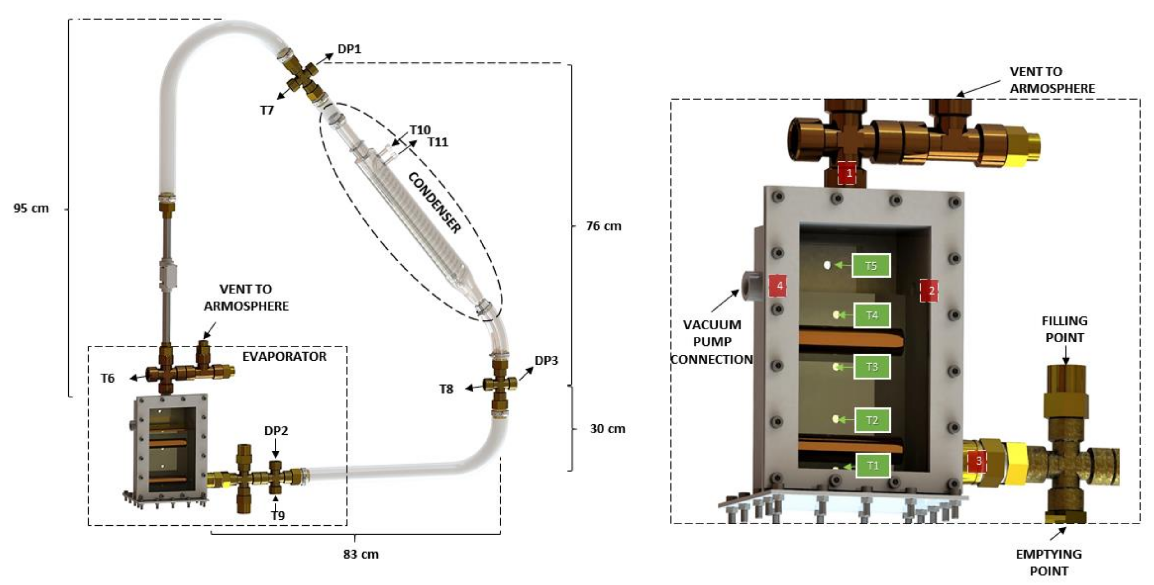
Figure 1 shows the experimental setup used in the present work for studying the thermal characteristics of the closed loop two-phase thermosyphon. In detail, this layout corresponds to a vertically oriented wickless heat pipe, where there is no interphase shear interaction as occur in simple TPCT (two phase close thermosyphon). The test rig has three main sections: boiling, cooling, and adiabatic middle zone.
2.2. Boiling Section
This is the vessel where the evaporator is located for the pool boiling process. It is a 100 × 87 × 210 mm AISI 314 L stainless steel resemblance of a tube-in-shell heat exchanger. It is in charge of collecting the desired NOVEC flow volume coming from a liquid reservoir. A 5-mm sheet of methacrylate was used in the front section of the tank to study the boiling phenomena. Two 20 × 90 mm cartridge heaters were used as a variable heat source, up to 500 W each, depending on the applied voltage. These were placed 35 mm apart in the interior of the tank. Moreover, four 13-mm holes were added around the structure. Following the nomenclature in
Figure 1: (1) allowed the vapor phase exit, (2) was used for pressure monitorization, (3) enable the condensate to return to the evaporator, and (4) was the vacuum pump connection point to lower the pressure and favor the fluid evaporation at a lower temperature, avoiding any possible interaction between the NOVEC and other external substances.
As a caution measure, a vent to the atmosphere was added after the evaporator outlet to prevent a prompt and step increase in pressure. Furthermore, as it can be observed
Figure 1, the filling and emptying control points were situated in the liquid phase section of the circuit. These four spots manually controlled by ball valves placed in each specific separated pipe.
The system is studied with a fluid charge of 1.4 L, which means a heat capacity of 2.47 kJ/K.
2.2.1. Cooling Section
Its main component is a 400 mm glass coil condenser, which has a specially formed 330-mm spiral inner tube, providing an adequate vapor path that enlarges the heat transfer surface between the vapor NOVEC and the auxiliary refrigeration loop. Their exterior diameters are 29 and 10 mm, respectively. This material was selected to have an insight into the heat transfer process taking place inside the condenser.
A secondary water refrigeration circuit was used to absorb heat from the vapor, thus closing the two-phase loop. Water circulation was regulated by means of an external pump, and its temperature set point could be manually fixed, as it was slightly conditioned by the room temperature.
2.2.2. Adiabatic Section
Two polyvinyl chloride (PVC) tubes were used to assemble the connection between both heat exchangers, with an exterior diameter of 17 mm for the bottom one (i.e., downcomer) and 28 mm the top one (i.e., riser), with both having a thickness of 1 mm. An additional isolation encircled the riser to minimize heat losses to the surroundings. It was decided to use such a flexible material in order to be able to modify the test rig structure if desired and optimize NOVEC flow. In contrast, the downcomer did not need to be isolated since condensate fluid flows through it at lower temperatures.
In this layout, the condenser was placed with a 45° angle of inclination with respect to the horizontal plane, as a middle ground position among different suggestions found in the literature [
29], which has been proved to be highly dependent on the volume of fluid present in the evaporator.
2.2.3. Data Acquisition
A set of sensors is located along the setup to register the main variables involved in the system operating. Twelve 3-mm K-Type thermocouples were used to collect temperature data. Five of them were placed 0.03 m apart inside the evaporator (T1–T5), four at the inlet and outlet of each heat exchanger (T6–T9), two for the secondary water loop (T10–T11), and the remaining one was used to track the room temperature (TROOM).
Two Sitrans P transmitters for differential pressure (DP1 and DP2), that measure difference from atmospheric pressure, were placed at the highest and lowest point of the loop, with the height difference between them equal to 0.76 m. Moreover, DP3 was used to monitor pressure at the condenser’s exit (
Figure 1). Since the pressure drop (i.e., ∆P) in the condenser was found to be negligible, measurements from DP3 were equal to the ones from DP1, with the former used for the control.
All of the data collected by the sensors was processed with “LabVIEW”, an effective tool for the testing, measurement and control of experimental rigs, saving all the variables in ten-second intervals.
2.3. Operating Principle
As previously mentioned, the TPCT (two-phase close thermosyphon) is a two-phase passive method of heat transference that fully relies on the concept of natural convection. Density variation experienced by a fluid in saturation conditions is the main driving force in this cycle, with the heat transfer performance highly affected by temperature difference, pressure difference, and refrigerant fluid flow 26. The temperature at the low level of the loop is generally greater than that at the top section in order to allow heat flow and counteract the gravity effect that keeps the liquid phase at the bottom part [
30]. This temperature gradient should surpass a critical value in order to overcome the retarding viscous forces and to further allow the head of liquid in the evaporator to move the volatile vapor towards the condenser, creating a two-phase flow [
31].
In this paper, a slight variation of the TPCT is presented, known as the CLTPT; instead of having a unique channel connecting the evaporator and the condenser, two pipes were used in order to separate the vapor rising from the evaporator, and the condensate descending due to the gravitational forces. Its main asset compared to common heat pipes is the avoidance of the entrainment or counter-current flooding limit. This parameter is closely related to vapor velocity, and it is reached when the shear stress present in the liquid–vapor interphase at the riser prevents the liquid from returning to the evaporator [
30]. Since in the present closed loop, the vapor and the liquid do not flow through the same pipes, this important limitation can be outweighed.
Previous studies have shown the importance of diverse parameters to stabilize the circulation, such as input heat transfer rates and working fluid filling ratios. The filling ratio, i.e., FR, known as the ratio of volume of working fluid to volume of evaporator section, is maintained between 55% and 80%. This variable has an important effect on the thermosyphon circulation, and it has been proven to be highly related to the optimum inclination angle of the condenser [
29]. In this particular case, the FR was slightly conditioned by the cartridge heater positions, as they should be covered by the fluid NOVEC while operating. Therefore, in the present study, the filling ratio will be 80% in any case.
Along these lines, the aspect ratio, i.e.,
AR, has been taken by some authors as a reference to compare various experimental configurations [
32,
33]. It is usually defined for evaporators that consist on a tube with the coolant flowing inside. For this type of evaporators,
AR corresponds to the ratio of the evaporator section length (
Le) to the inside diameter (
ID). For a circular-section tube,
ID is the diameter. Otherwise, for a rectangular evaporator cross-section, the hydraulic diameter is taken as
ID, and AR is calculated by Equation (1) in which d and w stand for the depth and width, respectively. However, for a pool evaporator such as the one used in the present work, this
AR formulation is not representative since the evaporator is formed by different elements (horizontal cylinders in the present paper) submerged in the liquid phase. For such case, an equivalent formulation of the
AR is the ratio of the area of the evaporator active surface (
Aev) and four times the pool horizontal cross section (
Acs), as shown in Equation (2). For the evaporator studied in the present paper installation, its value is 1.14.
Moreover, heat input to the evaporator section was assumed to be equal to the combined power input applied via the electric power from the cartridge heaters. On the other hand, the rate of heat absorbed by the condenser was obtained by Equation (3) in which
and
are the input and output temperatures of the cooling water passing through the condenser.
Finally, the thermal resistance of the TPCT (and particularly CLTPT), i.e.,
, is also defined as one of the thermal performance indicators [
34]. It was calculated by Equation (4) considering
to be the average temperature of the thermocouples located inside the cartridge heaters,
the average temperature of the water that cools the condenser, and
as the applied power input at the evaporator.
2.4. Working Fluid
As stated above, the coolant or working fluid is a capital element of any cooling system, since the coolant is in charge of removing the heat from the cooled region, transporting it and transferring it to the heatsink. Moreover, if the cooling system is a CLTPT, the coolant capacity to establish a natural flow circulation is a limiting fact to work efficiently. Thus, the coolant thermophysical properties play an important role in the behavior of the system.
In a pool boiling device, the fluid must work in fully developed nucleate boiling regime to operate with a high heat transfer and prevent an excessive superheating of the evaporator walls. However, the CHF point must never be overcome because, in that case, the system is displaced to a film boiling regime. Some authors, such as El Genk and Ali [
35], recommend maintaining the maximum heat flux below 70% of the CHF. The nucleate boiling heat flux in a pool boiling system can be estimated through the classical Rohsenow’s correlation shown in Equation (5) [
18].
This formulation allows visualization the most influential fluid properties to increase the heat flux for a minimum wall superheat. The first obvious parameter to consider is the boiling temperature since it sets the range of application of the fluid and can be a limitation for some fluids such as water, which is a superior coolant with regard to other properties. The thermal conductivity of the fluid, present in the Prandtl number, also has a great influence. It highly increases the fluid capacity to remove heat. Other important parameters are the flow viscosity, also present in the Prandtl number, and latent heat. For both cases, low values improve the heat transfer coefficient of the fluid. Otherwise, the CHF is commonly formulated through the Kutateladze’s and Zuber’s formulation shown in Equation (6) [
36,
37]. In this, the latent heat is the most important fluid parameter. Contrary to what happens with the heat flux, a high value of latent heat directly increases the CHF limit and, thus, the nucleate boiling range. As the coefficient Ccr is a geometrical parameter, the following fluid parameter to take into account is the vapor density. This means fluids with a high molecular weight will trend to a higher critical heat flux.
Taking these parameters into account, the coolant NOVEC 649 has been considered to be an adequate option to achieve high heat fluxes without excessive wall superheat. This is adequate for low or moderate power applications such as the system studied in this paper. Whereas water has an excessively high boiling point and other traditional coolants such as R134a or ammonia has sub-zero boiling points, NOVEC 649 has a boiling point of 49.8 °C at atmospheric pressure [
38,
39]. This makes it especially appropriate for multiple low-pressure applications. Some properties, such as the low latent heat and low viscosity, stimulate its nucleate boiling heat transfer. In contrary, its low thermal conductivity is a negative property on the heat removal capacity, which is common in most low-temperature coolants. The main thermal properties of NOVEC 649 liquid phase are shown in
Table 1. The low latent heat also causes a moderate value of the CHF heat flux. Based on Equation (6), values of 100 kW/m
2 should not be overcome for the cylindrical heaters used in the experimental installation. The data properties of the gas phase are not given by the manufacturer.
In addition to these properties, NOVEC 649 is chemically stable at temperatures lower than 300 °C as long as it is kept away from water contact. Its global warming potential is also considered extremely low, it produces a zero ozone depletion, and its lifetime in the atmosphere is 5 days, which is a great advantage over other classical coolants whose lifetime are usually hundreds of years [
38,
39]. This combination of properties makes it a highly desirable coolant from a health and environmental point of view.
Other fluids such as Freon modern compounds have also good cooling properties and also have a weak effect to environment. However, they need higher working pressures than 20 bar to operate at atmospheric temperatures which makes expensive the setups. The system presented in this work can be easily applied to low pressure applications due to the evaporation temperatures of NOVEC. In the present work, the experimental system is appropriate for temperature operating ranges from 20 to 80 °C and pressures from 0.5 to 2.5 bar.
2.5. Uncertainty Analysis
The information about the uncertainty of the instruments used in the measurements collection is given in
Table 2. The thermocouples used for measurements have an accuracy lower than 2.2 K in the range of temperatures of the experiments performed. The pressure gauge sensors have an uncertainty in the range of 0.01 mbar, which is difficult to determine since it depend of external factors but, in any case, it is always lower than 0.1 for all the tests. The parameter that provides the higher uncertainty is the power input. The manufacturer declares an error of +5% and −10% in the power supplied by the heaters. In addition, the control of the power supplied is not stable and this requires a strict supervision during the tests to correct the deviation from the set point. This supervision ensures that the maximum oscillation observed was lower than 2 W. These uncertainties also affect the thermal resistance of the system (Equation (4)) whose values for different power inputs are shown in the section of results. The relative error of this parameter is calculated as shown in Equation (7). According to this formulation, the maximum possible error of this parameter in all experiments performed is less than 21%, which is mainly influenced by the error in the power input.
3. Results and Discussion
As stated above, the studies of the type of CLTPT gravitational channel are limited, especially when the coolant is a modern fluid such as NOVEC 649. In this section, the influence of different parameters in the system performance is studied to assess its capabilities and possible operating limitations. Otherwise, some instabilities were observed during the transient working of the system up to the flow circulation being established. Therefore, part of the tests is focused on the transient evolution of the system and the stability analysis. The evolution of the internal pressure and the temperatures distribution inside the system are also studied as well as heat transfer parameters, such as the convection coefficients and thermal resistance of the thermosyphon.
3.1. Transient Behavior
Several experiments were carried out to study the evolution of the system up to the steady state operating is reached. These tests start by setting a constant power input which remains constant (except for the instabilities experienced by the source) until the temperatures and pressures measured reach a steady state. In some of the experiments, the stability and the ability of the system to adapt to power input changes is studied. In these, the experiments also start with a constant power input until the steady state is reached and then, the power input is increased and kept constant again until temperatures and pressures stabilize again. This process can be repeated for several power increases.
The whole heat transfer cycle for which the experimental setup is designed does not occur immediately when heat is supplied in the evaporator. Even if the operating conditions are constant, the system passes through several processes until the fluid circulation is set up and the steady state is reached. The fluid circulation is not easy to achieve, mainly due to the difficulty that the vapor finds to advance through the pipes and reach the condenser at the beginning of the process. This causes a pressure raise, which increases the evaporation temperature of the fluid. To favor the setup behavior, the pressure was decreased up to DP1 showed −450 mbar for all tests.
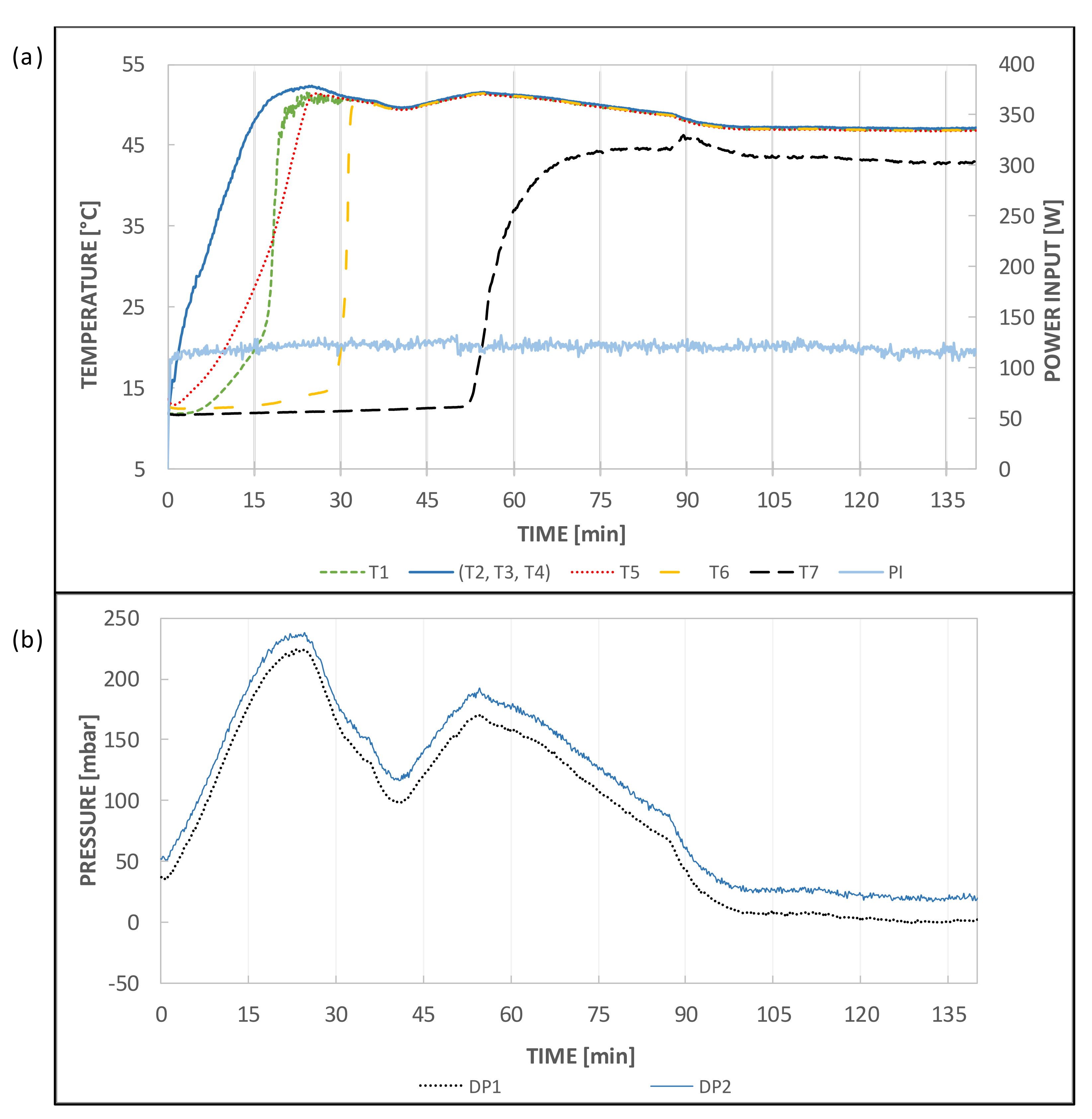
To analyze the transient behavior of the CLTPT, the results of a representative test are shown in
Figure 2. This test was performed by applying a constant power input of 120 W in the evaporator, an initial temperature of 12 °C and the same temperature in the condenser flow. A moderate power input was used, because higher values produced an abrupt pressure increase that may damage the facility. The thermocouples T2, T3, and T4, whose differences are negligible, show the temperature in the boiling section; T6 shows the temperature at the beginning of the riser pipe, and T7 shows the temperature at the inlet of the condenser. The other temperatures are commented in the following section. In the same way, two pressure measurements are shown, DP2 at the evaporator and DP3 at the condenser outlet (locations shown in
Figure 1). The pressure DP1 is not shown since it showed to be the same as DP3 in all the tests performed.
At the beginning of the heating process, both the temperature and pressure increase at the boiling section. However, the temperature in the riser pipe remains low, which means that the vapor is not advancing across the riser pipe. Then, at approximately minute 25, the pressure starts to decrease, and the temperature in the riser abruptly increases up to reach the same temperature of the boiling section, which is a sign that the vapor is advancing through the riser pipe. The pressure continues decreasing until approximately minute 40, at which point it starts to rise again, and this happens because the vapor needs a higher pressure to descend after it has reached the top of the loop. At approximately minute 50, the temperature of T7 increases, and after that, the pressure decreases again. This is a sign that the vapor flow reaches the condenser and fluid circulation is established. From this point, both the pressure and temperatures continue their slow decrease up to find the steady state. The temperature of T7 is lower than that of T4 and T6 at the steady state due to heat loses. For higher power inputs, this difference is insignificant, as can be seen below.
This difficulty in establishing the flow circulation is due to the effect of a closed thermosyphon heat pipe that occur in the boiling section and in the riser pipe, while the walls of these elements are cold. The vapor generated in the evaporator is condensed before it can circulate through the loop and reach the condenser. Even if the facility is well isolated, this happens due to the thermal inertia of the constructive elements. Therefore, the internal pressure is increased and, hence, the coolant evaporation temperature is increased. In contrast, when the flow circulates, a pressure relief is produced and the boiling decreases, as can be observed when the system approaches the steady state.
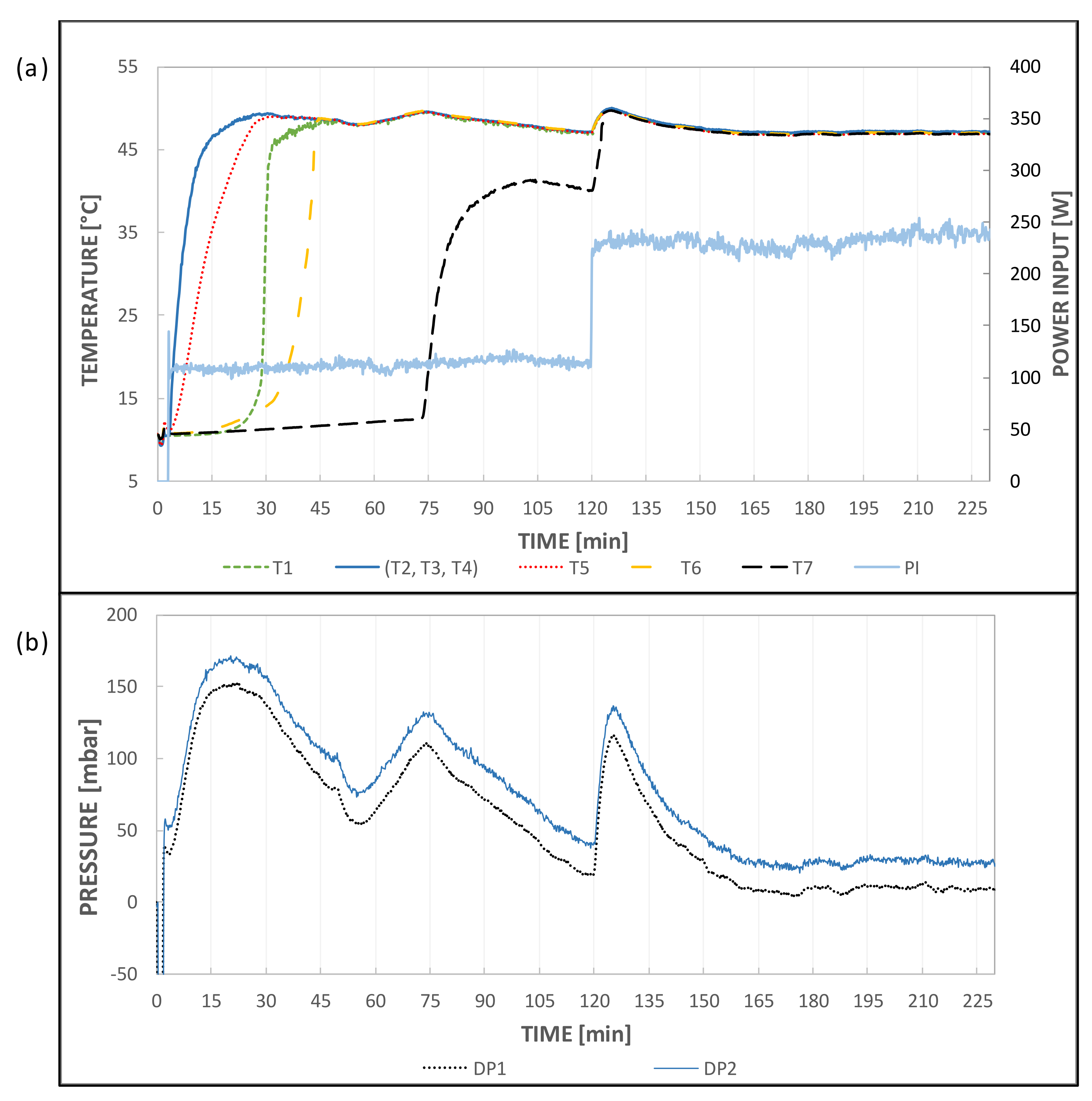
As it is also interesting to analyze the system response to changes in the power input, an experiment was performed in conditions similar to the one shown in
Figure 2, but the power input was doubled when the flow circulation is established.
Figure 3 shows the evolution of temperatures and pressures, and the power input increased at minute 120. The most significant result is the quick adaptation of the system to the change, especially by the temperatures. Once the fluid is circulating along the loop, the change of the power input produces an abrupt pressure increase, with a consequent increase of the boiling temperature; however, the vapor circulation relieves this pressure increase and the system returns quite quickly to the same steady state. The unique noticeable difference is the T7 temperature, which is virtually the same as that of T4 and T6 when the power input is enough to compensate for the heat losses of the pipes. The fact that the steady state temperatures and pressures are independent of the heat input (as long as the condenser is able to remove the power input without a vapor overheat) is very important for design and operating considerations.
The abrupt pressure rise produced after the power increase might be caused mainly by the higher rate of vapor generation in the evaporator and the slow response of the condenser to increase its condensation rate. Nevertheless, in some cases, the phenomenon of geyser boiling occurs in the riser pipe, which contributes to this transient pressure increase. This phenomenon was deeply studied by Casarosa et al. [
40]. Although geyser boiling usually occurs in systems where the evaporator is part of the riser pipe (not this case) [
41], it can happen due to the liquid condensing in the pipe and accumulating at the bottom and the vapor ascending through the pipe that generates the geyser effect. This phenomenon disappears when the temperature of the riser walls equals the boiling temperature and no more fluid is condensed, but it can remain if the pipe is not adequately insulated. This effect is not usually expected in a pool boiling system if the boiling section is not full of liquid. Nevertheless, it was observed in this facility by using a transparent riser.
3.2. Temperatures Distribution
To understand the whole system behavior, an accurate assessment of temperatures evolution in the most crucial points was performed. These temperature measurements were collected at seven points (T1–T7), as previously shown in
Figure 1. Five of these measurements are located in the boiling section, T1–T4 are submerged in the liquid NOVEC, and T5 is also located inside the boiling section but in the vapor zone. T6 is located at the beginning of the riser pipe, and T7 is in the pipe down to the condenser.
As showed in
Figure 2 and
Figure 3, the first significant result is that all the temperatures inside the liquid phase, which are located over any of the evaporator heater cylinders, i.e., T2, T3, and T4, are virtually the same. This is caused by the natural convection accelerated by the vapor bubbles that stir the fluid in the evaporator chamber and homogenize the fluid temperature over the heaters and their differences are negligible. In contrast, T1, which is only a few millimeters under the lower heater surface, suffers several minutes of delay in its heating. The gas region of the boiling section (T5) starts its heating almost immediately after the liquid, but with a lower power input. The delay in the heating of T6 is also noticeable. It is very slow at the beginning, and it increases abruptly at approximately minute 25 of the test to meet the temperature of the previous thermocouples of the boiling section. It is important to point out that T5 and T6 are separated by only a few centimeters; however, the heating of T6 is delayed by approximately 10 min. This relates the difficulty that the vapor encounters in starting to advance though the riser pipe. Finally, as shown in previous sections, T7 also is heated with a significant delay compared to T6. The heating of T7 means the fluid circulation is already established and, from that point, all temperatures are practically the same. In the experiments in which the power input is increased, such as the one shown in
Figure 3, all temperatures (T1–T7) have practically the same values. A slight increase in all temperatures is observed after the power input increase, and then, the system slowly returns to the same operating point. This shows that there is a high thermal homogeneity in the whole system when the fluid is circulating and that homogeneity is kept even if the power input is increased.
3.3. Stability Analysis and Response to Power Input Variations
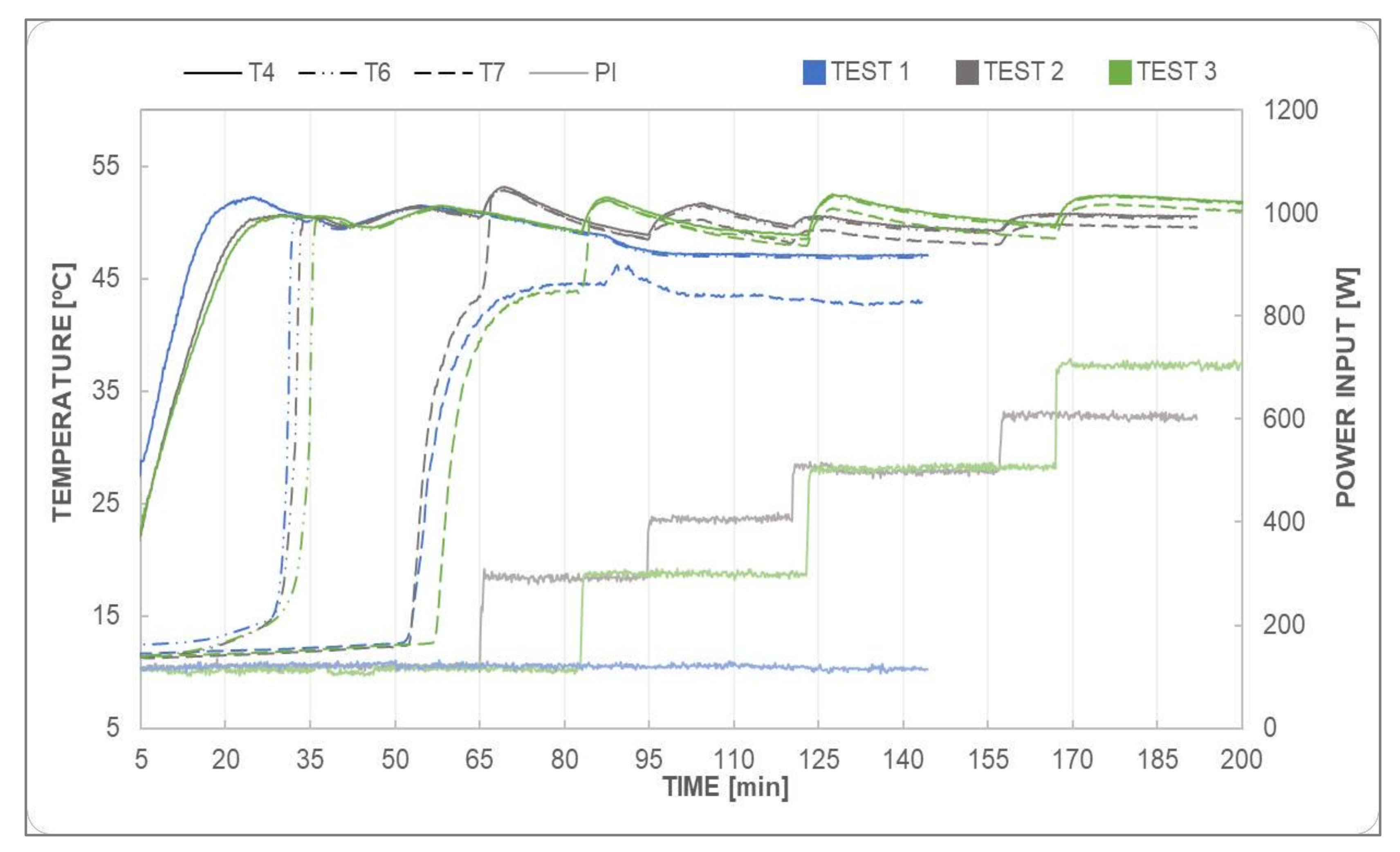
Following the transient behavior of the cycle, the stable operation of the CLTPT is reached. Three different experiments were run for various power input increments, which can be observed in
Figure 4. For the first test (shown in blue), the power input was maintained at 100 W; for the second test (shown in grey), a 100-W periodic increase was executed up to 600 W; and for the last one (shown in green), 200-W increments were tested until reaching 700 W.
During the first test, the heat supplied is maintained constant in order to ensure temperature stabilization along the loop, which contributes for the proper operation of the thermosyphon. After approximately 30 min, T4 and T6 are brought up to the same level, which means that the vapor is ascending throughout the riser. On the other hand, for the second test, the heat load is set to 300 W immediately upon the one-hour mark, consequently boosting T7 up to 53 °C. This same procedure is undertaken for the third test; the heat load increment is applied after 80 min of operation, and the same result as for the second test is obtained.
However, for the first test, it is important to notice that with such lower set point, despite the insulation, there are some heat losses along the loop. T7 is constant but 5 °C lower than T4 and T6 (this same behavior can be appreciated in
Figure 5). This is most likely caused by the difficulty in balancing out heat losses in the adiabatic section and even in the evaporator itself.
This obstacle is overcome in the second and third tests, where higher power input set points allow for heat loss reduction due to greater vapor velocity along the riser. Additionally, the fact that higher heat input is supplied in the evaporator allows for more energy to be available to stimulate fluid flow. In both cases, T7 is maintained around 50 °C, being closer to T4 and T6. Despite the more noticeable initial temperature rise for the highest power inputs, stabilization is reached around the same conditions (
Figure 4), which confirms the already mentioned hypothesis: the steady state temperatures and pressures are mostly independent of the power input for moderated values of the heat flux in the evaporator. Nonetheless, for power inputs above 1 kW, a modest increase in temperatures could occur.
It is essential to mention that all the power input increments were equally distributed among the resistances to avoid temperature stratification in the evaporator, which could potentially lead to instabilities and back-flow.
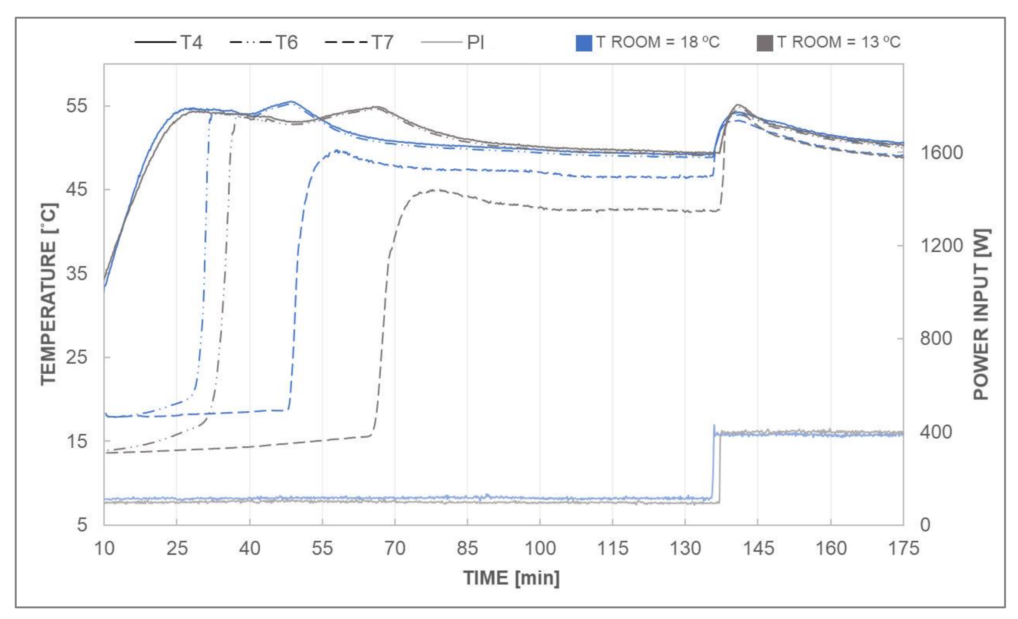
In addition, the room temperature effect on the thermosyphon was tested by running two more tests with a 5 °C room temperature difference. The results can be observed in
Figure 5. For the first test (shown in blue), with a room temperature of 18 °C, the circulation starts after 47 min of operation, while for the second one (shown in gray), with a room temperature of 13 °C, it begins at the 65-min mark. This suggests that higher environmental temperature allows the transient behavior to be overcome faster. Moreover, it is interesting to note that despite the initial operational difference, stabilization is again achieved at 50 °C, and stays that way even after a 300-W power input increment at minute 135, proving once more the safety and reliability of the NOVEC CLTPT.
Some additional observations regarding the boiling behavior in the evaporator showed that, for lower temperature differences, bubbles departing from the heated surfaces were rather spherical in shape, small, and did not coalesce; meanwhile, for higher superheats, bubbles tended to merge and form bigger spheres ascending to the top evaporator zone. Nonetheless, uncontrolled pool boiling was not experienced, and funnel-shape bubbles were not observed, even for the highest power inputs. As expected, the higher the power input, the higher is the heat transfer coefficient due to smaller temperature difference. Whereas R1 reached the CHF point for a heat flux of approximately 98 kW/m2, no sign of approaching to CHF was observed for R2 for power inputs up to 100 kW/m2. This is also caused by the ascending fluid from R1, which breaks any vapor film and keeps the whole cylinder in a nucleate boiling regime. These results can be important for the design of tube bundle evaporators since their performance can be increased by distributing the higher heat fluxes to the upper tubes.
3.4. Internal Pressure Evolution
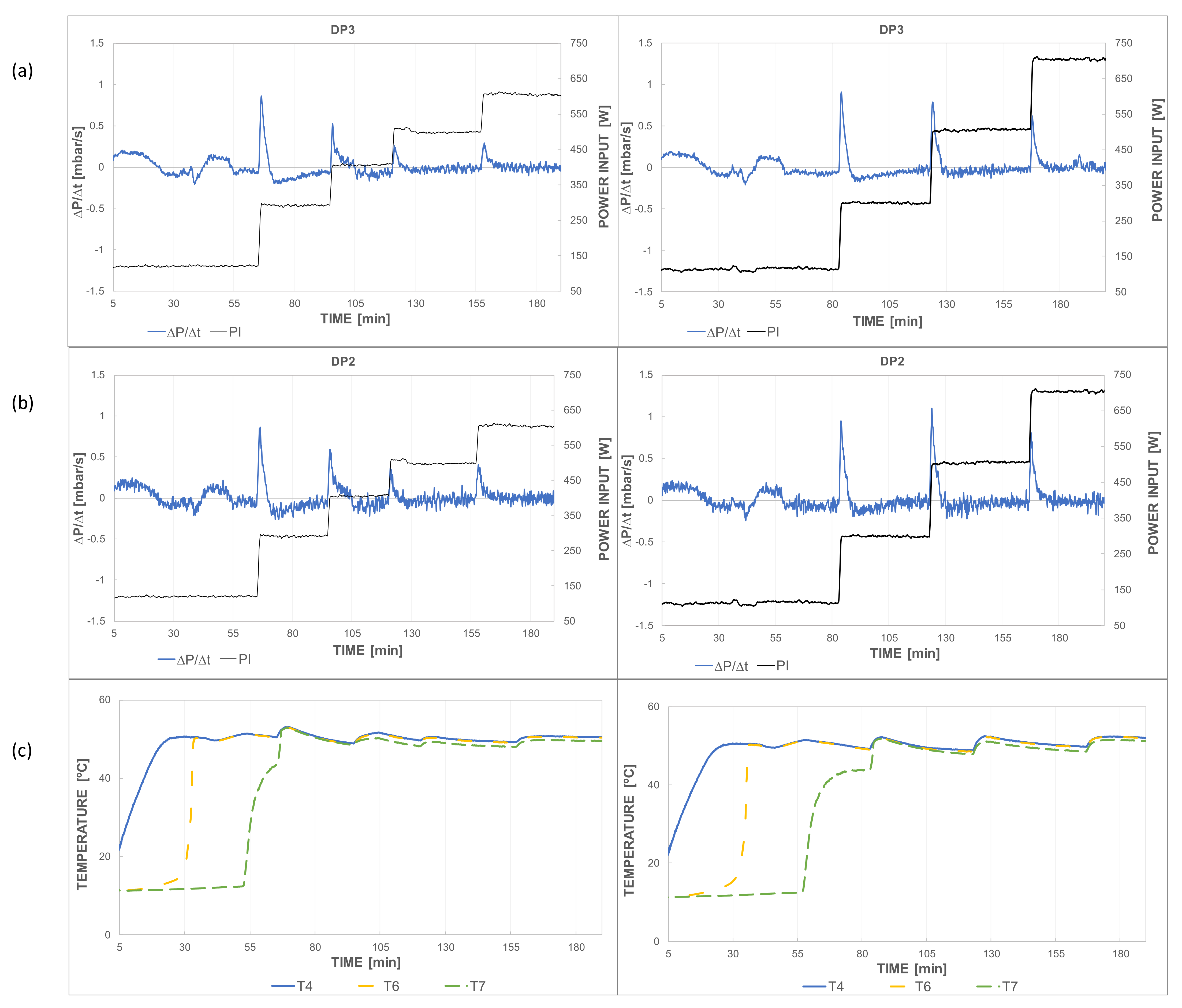
Figure 6 shows a comparison between the power input and the pressure evolution in the loop from two tests performed in equal environmental conditions. The time-variation in pressure is described as the ratio of the pressure difference in ten seconds of sampling time. It should be kept in mind that the pressure increase affects the boiling temperature, not only compromising the thermosyphon circulation but also presenting a hazardous situation for the facility safety. Therefore, it is convenient to perform low power input increments in order to produce minor effects on the internal pressure, allowing for a faster stabilization of the variables around the loop.
As observed in
Figure 6, pressure boosts take place when either a temperature increase is produced (first peak at around minute 30 in both cases), or when the power input rises (the following peaks in each graph are synchronized with heat input increase). However, it is important to notice that the CLTPT is capable of stabilizing after all the variations, taking up to ten minutes to reach the steady situation in every test. Moreover, if both columns in
Figure 6 are compared, it is clearly demonstrated that higher heat input increments consequently produce higher pressure boosts, which could potentially encourage the appearance of the already mentioned geyser boiling phenomenon. Thereupon, if the heat input to be absorbed in the evaporator is maintained constant during operation, pressure should be stable once the initial transient behavior is surpassed.
Finally, from both differential sensors represented in this same figure, it is evident that the one showing more variation is DP2, considering its location at the bottom section in the experimental setup (
Figure 1). Higher power inputs, lead to higher condensation rates, which subsequently increase the liquid presence in the downcomer. This is perceived by higher pressure peaks, and it is balanced out when internal pressure drops back to atmospheric level.
3.5. Thermosyphon Thermal Resistance
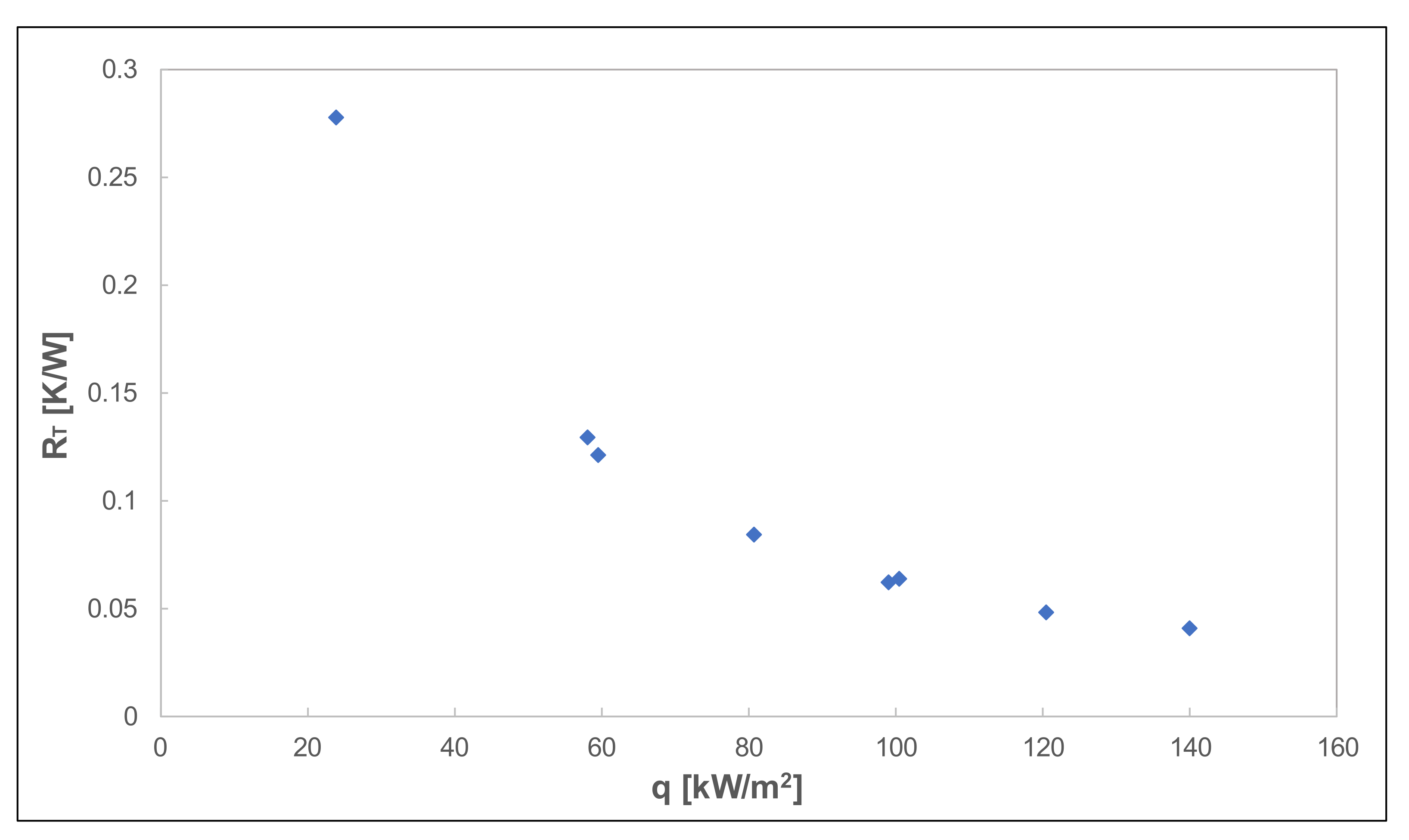
Figure 7 shows the thermal resistance of the CLTPT, as already mentioned in
Section 2.2. The greater the power input is, the lower is the thermal resistance in the loop, which is directly in accordance with the conclusions drawn from the stability analysis in
Section 3.2. Higher power inputs endorse faster thermosyphon operation, with reduced heat losses, hence bringing the possibility of dissipating larger heat flows in the evaporator. For a power input larger than 80 kW/m
2, the thermal resistance presented by the loop is nearly negligible.
3.6. Evaporator Heat Transfer Analysis
An analysis of the heat transfer on the evaporator heaters was carried out to study the heat flux effect and temperature difference on the two heaters and how their locations affect the cooling capabilities of the fluid. A thermocouple situated in the cartridge heater’s interior is used to measure its internal temperature.
Figure 8 collects the results obtained all tests measured when the steady state is reached. From
Figure 8, it is obvious that the top heater has higher heat fluxes, since it takes advantage of the already heated ascendant flow coming from the bottom heater.
For lower temperature differences, bubbles departing from the heated surfaces were rather spherical in shape, small, and did not coalesce; meanwhile, for higher superheats, bubbles tended to merge and form bigger spheres ascending to the top evaporator zone. Nonetheless, uncontrolled pool boiling was not experienced, and funnel-shape bubbles were not observed, even for the highest power inputs. As expected, the higher the heat flux, the higher is the temperature difference due to smaller temperature difference. Whereas the bottom heater reached the CHF point for a heat flux of approximately 98 kW/m2, no sign of approaching to CHF was observed for the top heater for power inputs up to 100 kW/m2. This is also caused by the ascending fluid from R1, which breaks any vapor film and keeps the whole cylinder in a nucleate boiling regime. These results can be important for the design of tube bundle evaporators since their performance can be increased by distributing the higher heat fluxes to the upper tubes.
3.7. Discussion
Summarizing the results of all the experiments, it has been observed that the system works with robust operation and can be easily implemented in a variety of low pressure cooling systems. The advantage of being a system that works with a pool boiling regime allows to cool elements of complex geometries. The main difficulty for the correct functioning of the system is the difficulty to start the circulation of the fluid throughout the loop. That is the reason for the emphasis on the study of transient behavior. The main reason for these transient problems seems to be the condensation of the vapor rising through the riser pipe due to heat losses produced by the thermal inertia of the pipes and the effect of the section reduction in the tubes connections, which in combination favor geyser boiling. Nevertheless, once the flow circulation is stablished, the system shows continuous operation and smooth adaptation to increases in the power input, returning to the same pressure and temperature point despite transporting a higher heat flux.
The results also showed reasonably good heat transfer capabilities. The overall thermal resistance analysis of the system shows that when steady state is reached, the system is efficient in removing heat. Values around 0.05 K/W are shown for high heat fluxes, which are values on the order of other CLTPT. This is a reasonably good performance of the system considering that vapor is the unique transport agent.
Another interesting result can be seen in the analysis of heat flow dissipated in the heaters. The heater located at the top of the boiling section shows clearly lower temperature differences with the fluid for the same heat flux. This is caused by the stirring produced by the lower heater which promotes a higher heat convection. This also prevents the upper heater from reaching the CHF with the same heat flux as the lower heater. This result may be an important consideration for the design of evaporators that cool elements with different heat fluxes.
Regarding the performance of NOVEC as a coolant, it shows a similar behavior to other refrigerants such as Freon type fluids. Nevertheless, this has an evaporation point of 49.8 °C at atmospheric pressure. This makes it an appropriate fluid for systems operating in low pressure and temperature ranges.
4. Conclusions
This work studies the thermal behavior of a CLTPT with NOVEC 649 as working fluid in which the evaporator works in the pool boiling regime, and pure vapor is the heat transport agent which is a cooling system not commonly found in the literature. The work novelty is the study of the transient evolution and stability analysis of internal pressure and temperatures of several points, as well as the heat transfer of the system according to the different positions of the heaters.
The system presents difficulties to start the fluid circulation, and instabilities that affect the boiling temperature are observed as the pressure increases. The boiling section is heated to reach the boiling temperature, but the vapor does not reach the condenser at the beginning of the experiments. Two pressure increases are needed by the system to force the vapor to advance through the riser pipe and descend to the condenser. Once the circulation is established, the pressure and temperatures of the system converge to stable values. Even after aggressive increases in the evaporator heat flux, the system returns to the same steady values.
A stability analysis showed that the pressure and temperatures in the steady state are independent from the heat input in the evaporator, as long as the condenser is capable of dissipating the whole power without a higher temperature difference. Even for a 600% power input increase, the system converges to the same working pressure and temperature. A higher environmental temperature has an important influence to accelerate the stabilization time; nevertheless, it does not affect to the system steady state.
The temperature inside the boiling section is virtually homogeneous in the liquid phase from the beginning of the tests except the bottom of the chamber, under the lower heater, whose heating is delayed. The vapor in the boiling chamber, in the riser pipe and in the condenser inlet suffers successive heating delays. Nevertheless, all these temperatures are equal when the flow circulation is stablished, even if the heat input is increased.
The overall thermal resistance decreases with heat flux converging to values of about 0.05 K/W. These are typical values in the CLTPT, indicating the good performance of the system despite working at low pressure with vapor as the only transport agent.
Heat fluxes were analyzed for the heater surfaces (two horizontal cylinders vertically separated 35 mm) for the temperature difference to fluid. The results showed clearly higher heat fluxes for the upper heater caused by the stirring flow that rises from the lower heater. It was also observed that the lower heater reaches the CHF point with a lower heat flux.


