
Real-Time Approximate Equivalent Consumption Minimization Strategy Based on the Single-Shaft Parallel Hybrid Powertrain


Abstract
:1. Introduction
2. Hybrid Powertrain System Configuration and Modeling
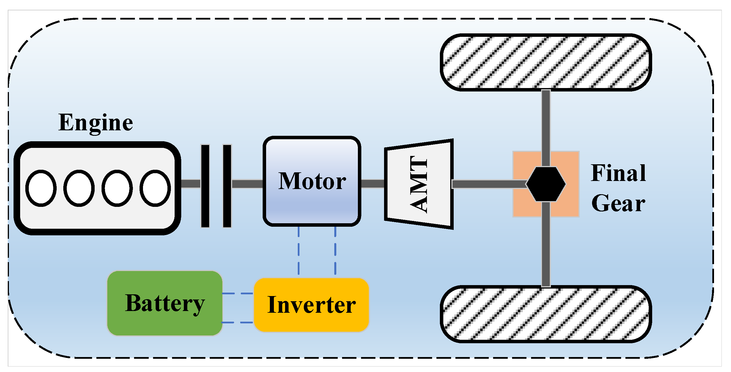
2.1. Hybrid Powertrain Configuration
2.2. System Modeling
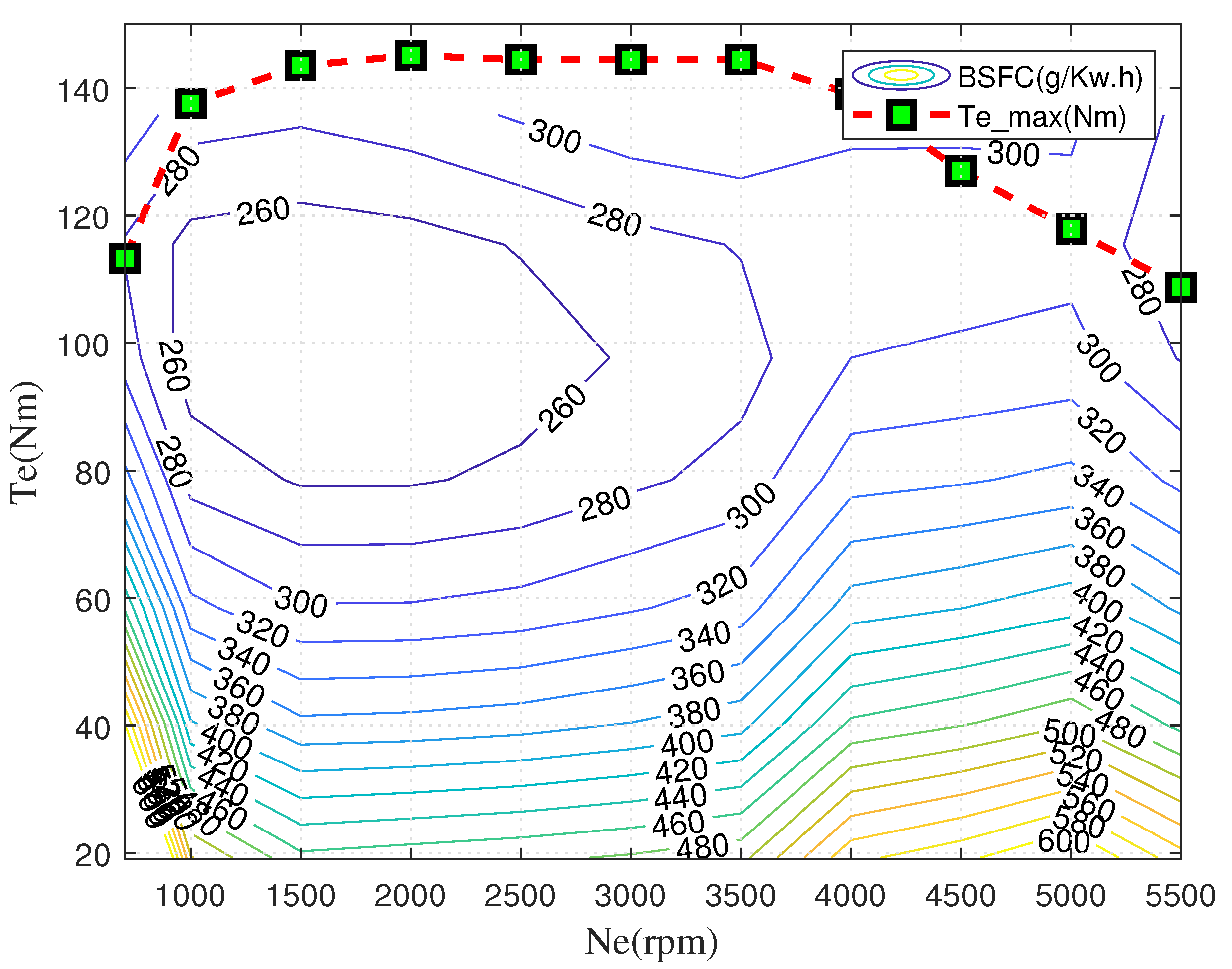
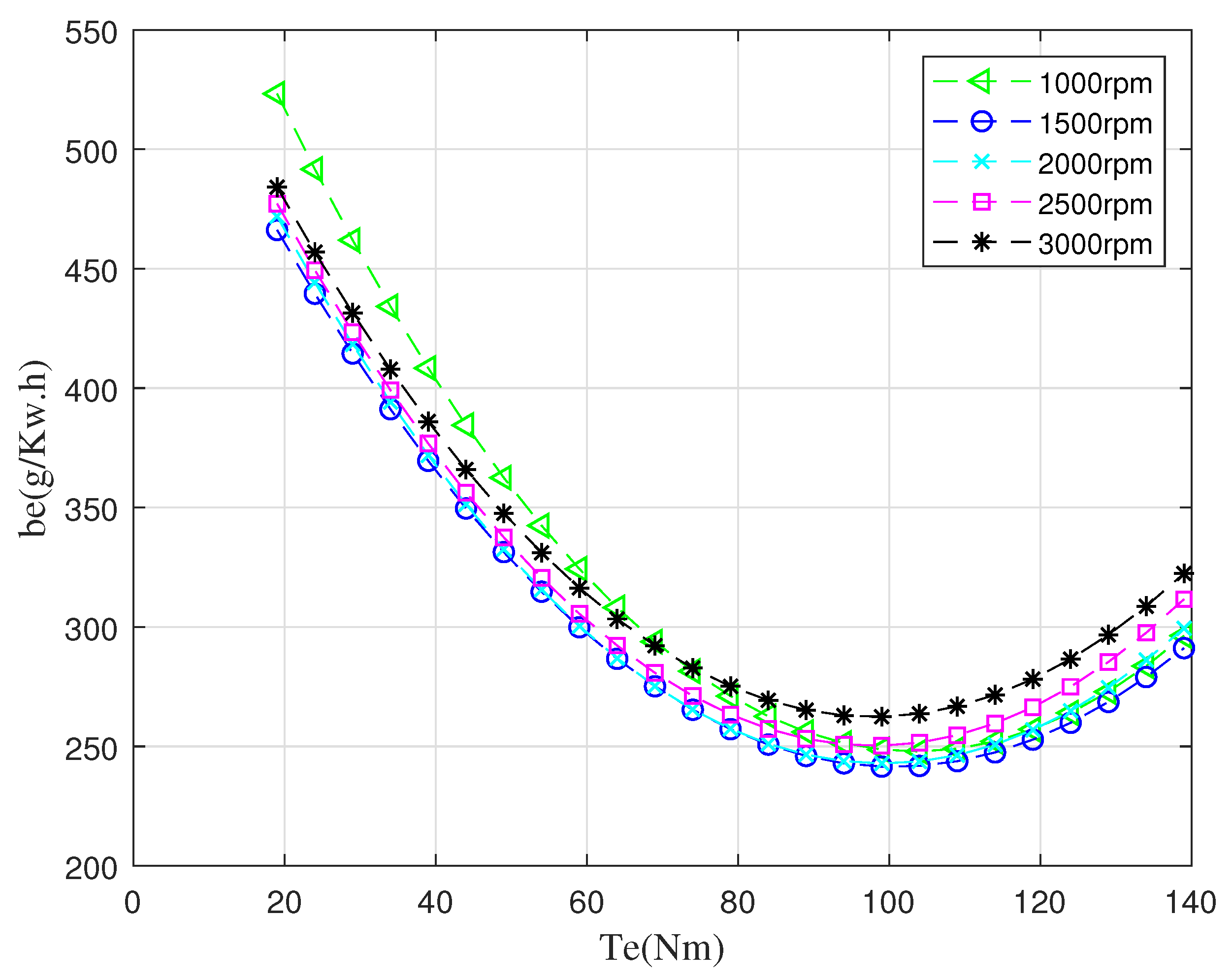
2.2.1. Engine Model
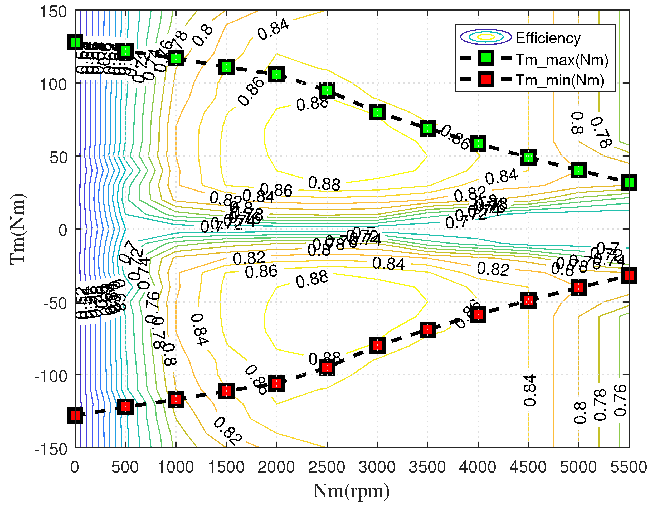
2.2.2. Motor Model
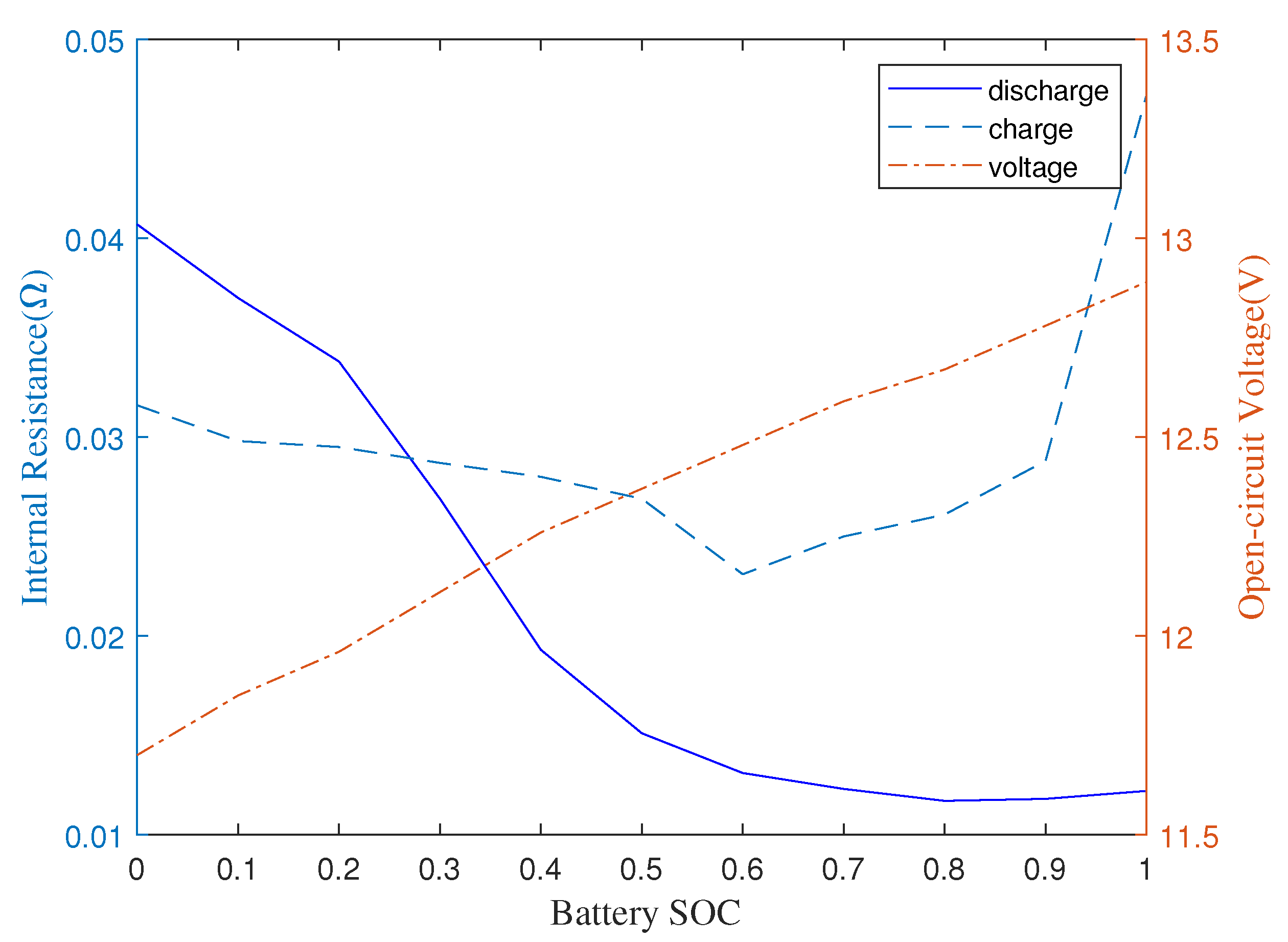
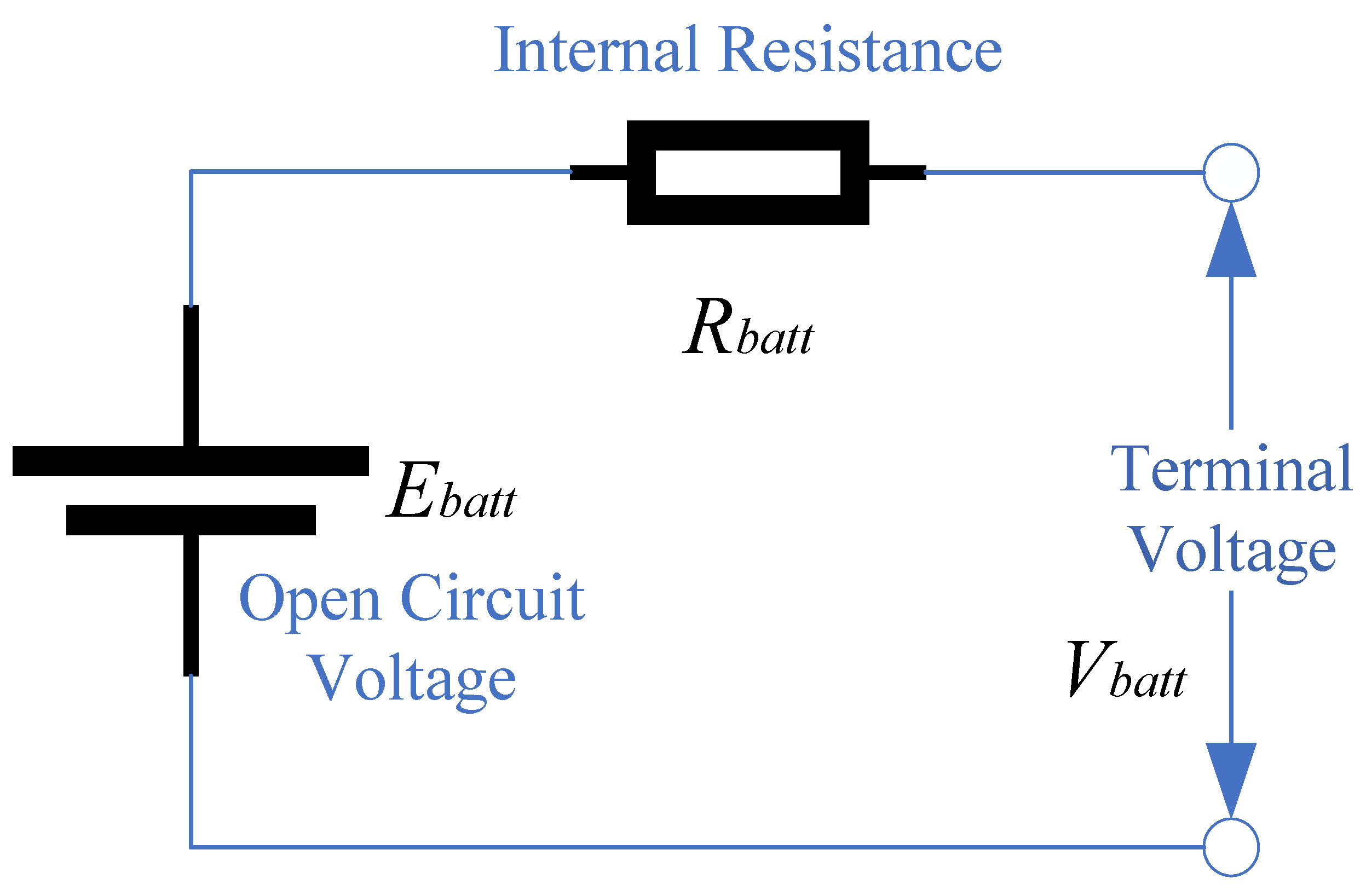
2.2.3. Battery Model
2.2.4. Longitudinal Dynamics Model
2.2.5. Driver Model
3. Energy Management Control Strategies
3.1. Energy Management-Based Ruled
3.2. Approximate-ECMS Strategy
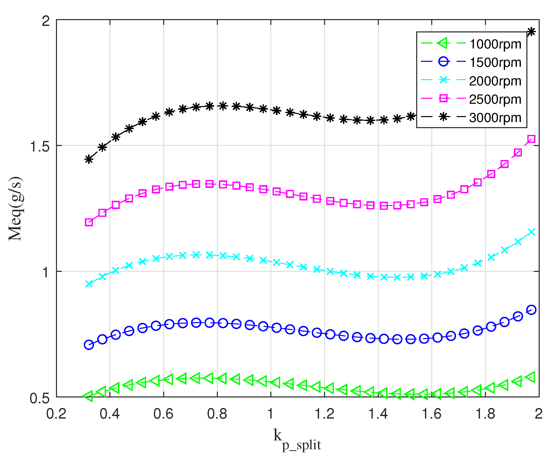
3.2.1. Power Allocation Factor
3.2.2. Basic of ECMS
3.2.3. Approximate-ECMS
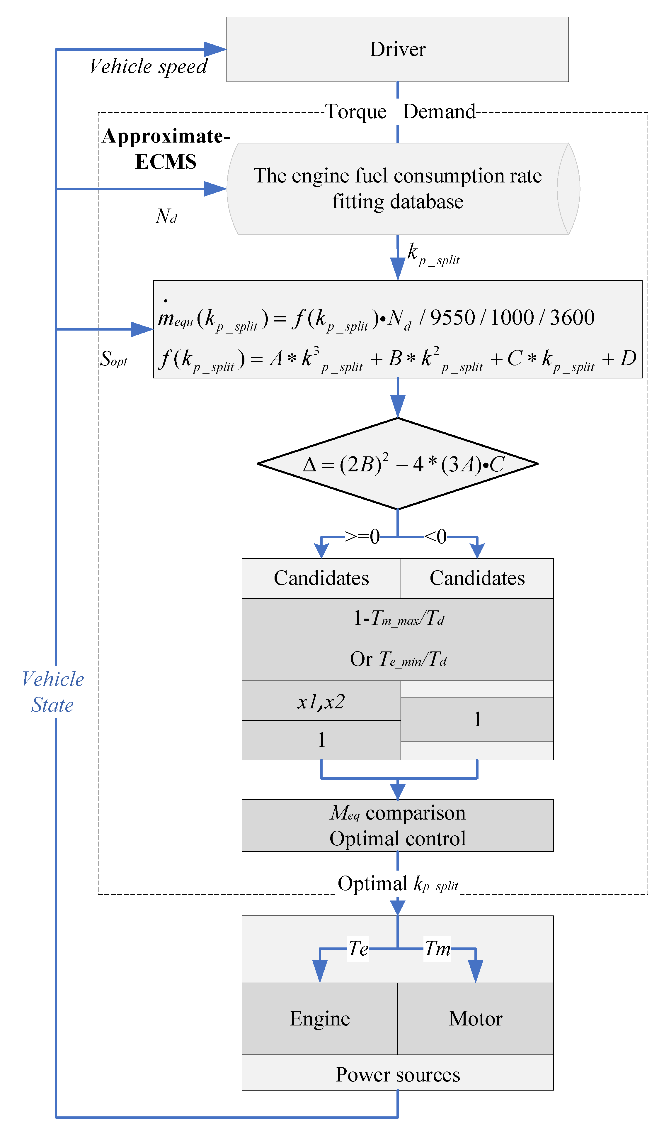
3.2.4. Flow Diagram of the Approximate-ECMS
4. Equivalent Factor Optimization Based on DPSO-GA
4.1. Hybrid DPSO-GA-Based Optimization Algorithm
4.1.1. Basic Principle of Dynamic Particle Swarm Optimization
4.1.2. Procedures of DPSO-GA
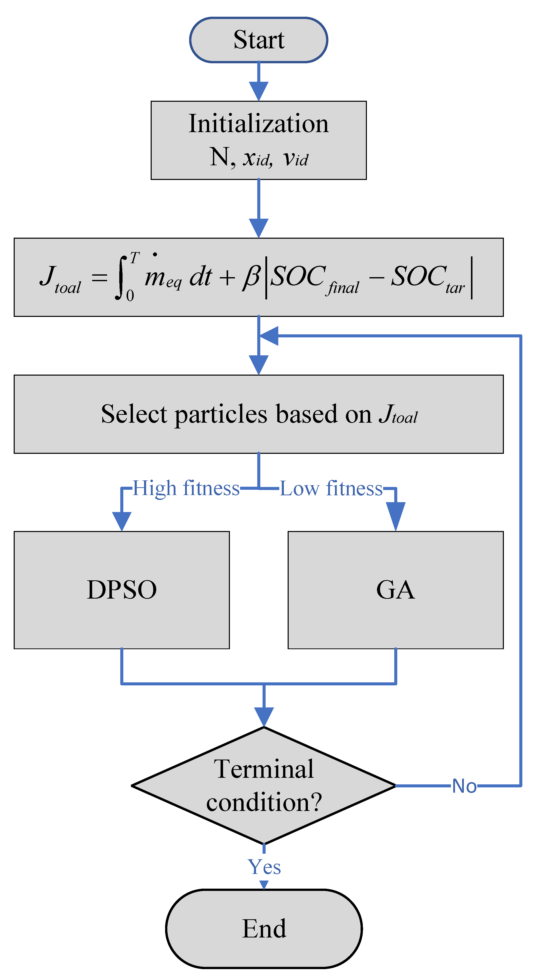
- Initialize particle swarm including swarm number N, particle position , and velocity . Initialize and of the particles, which are the initial value of the equivalent factor and its variation, respectively.
- The objective function: The goal of optimization is to achieve equivalent fuel consumption under typical driving cycles and to keep the difference between the final value of and the target value of SOC to a minimum, as shown in Equation (44).where is the objective function; is the instantaneous fuel consumption obtained from Equation (13); T is the end time of driving cycles, and are the final and target value of SOC, respectively; is the weighting factor.
- Select particles based on ranked fitness and update: After initializing the particle swarm, the particle fitness is ranked according to the objective function. The function with high fitness is selected for particle swarm algorithm update based on Equation (43) and for low fitness values a genetic algorithm update is performed.
- End: Set the termination condition. If the termination condition is not satisfied, execute steps 2–3 until the particle search satisfies the termination condition. Then obtain the best solution.
5. Simulation Results and Discussion
5.1. Model and Settings of the Vehicle
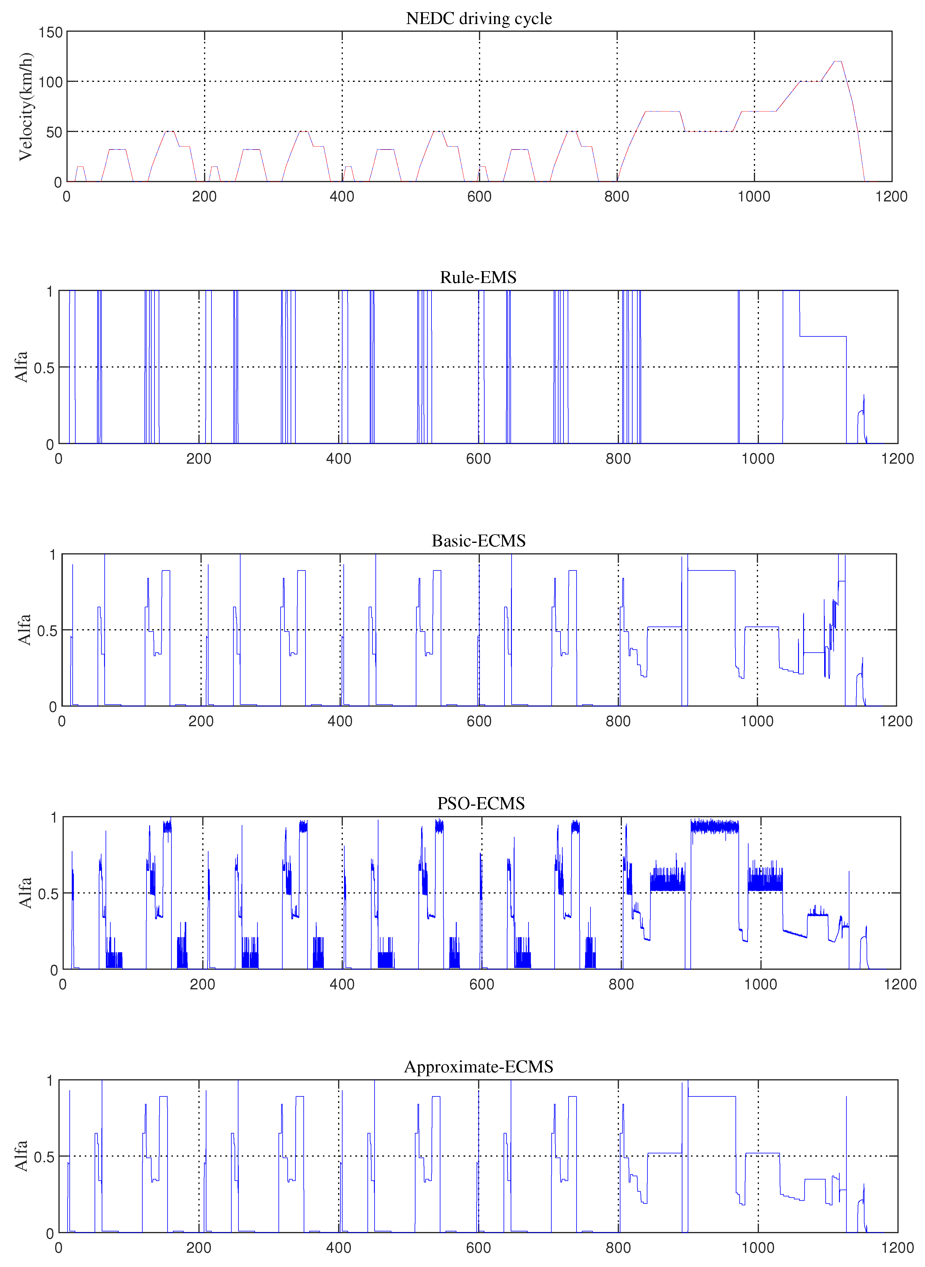
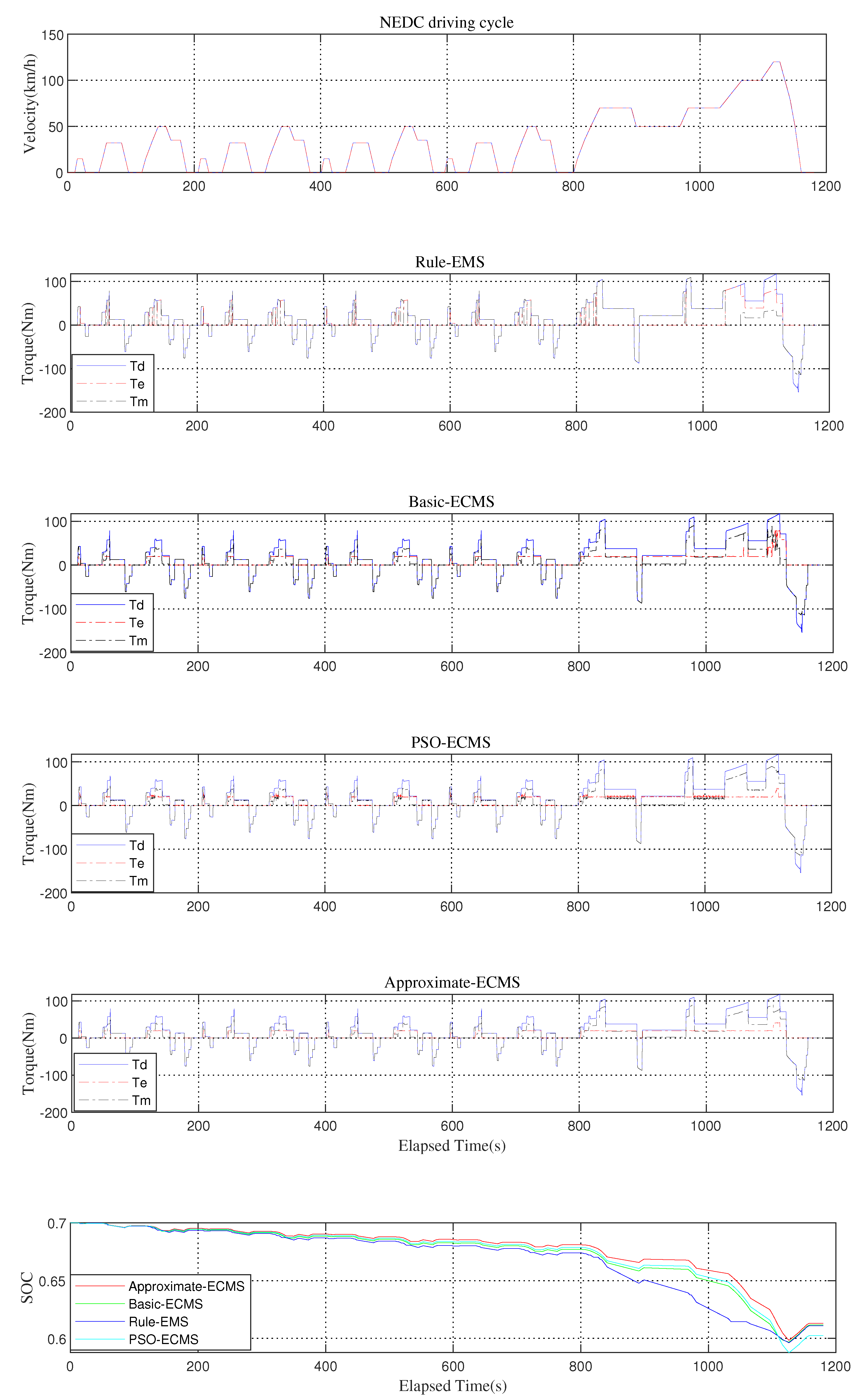
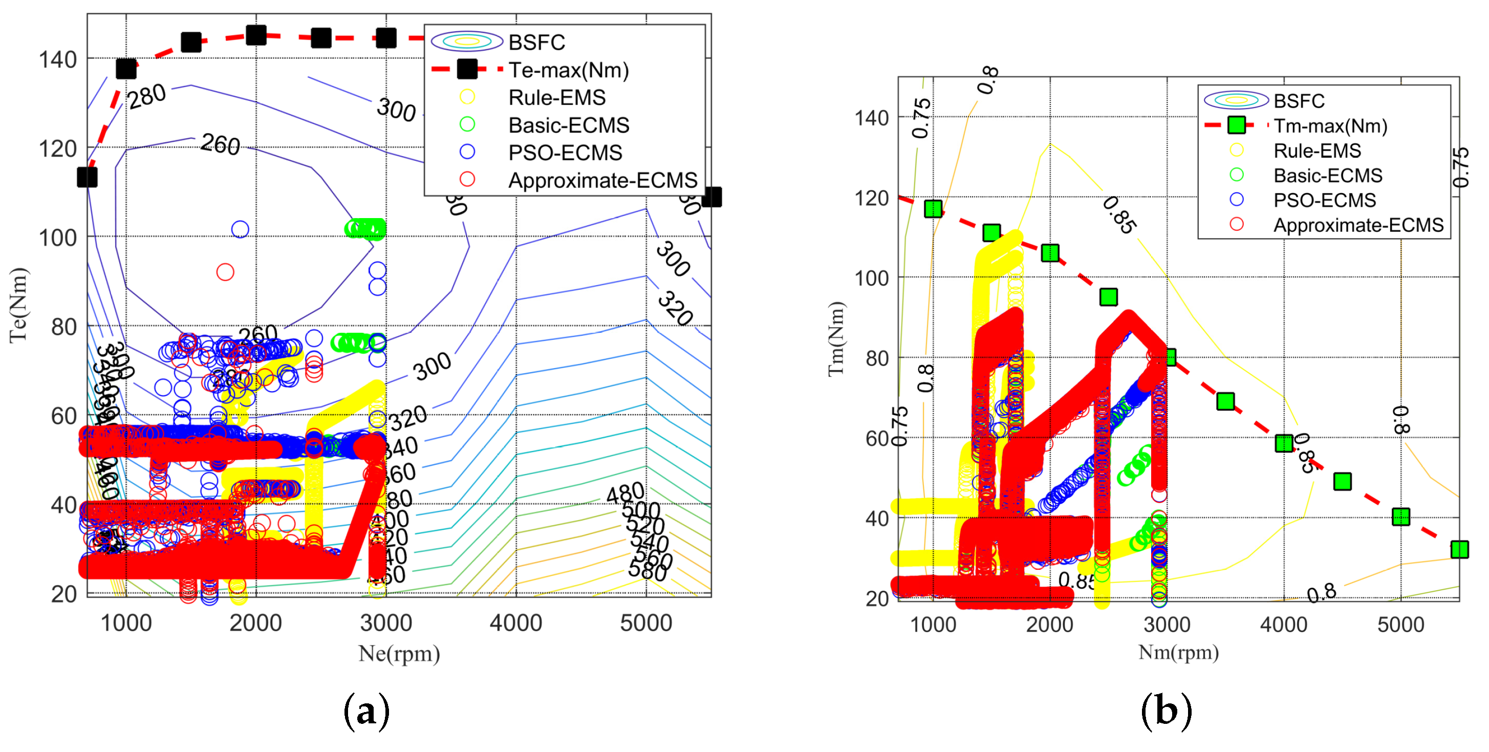
5.2. Comparison of Rule-EMS, Basic-ECMS, PSO-ECMS, and Approximate-ECMS
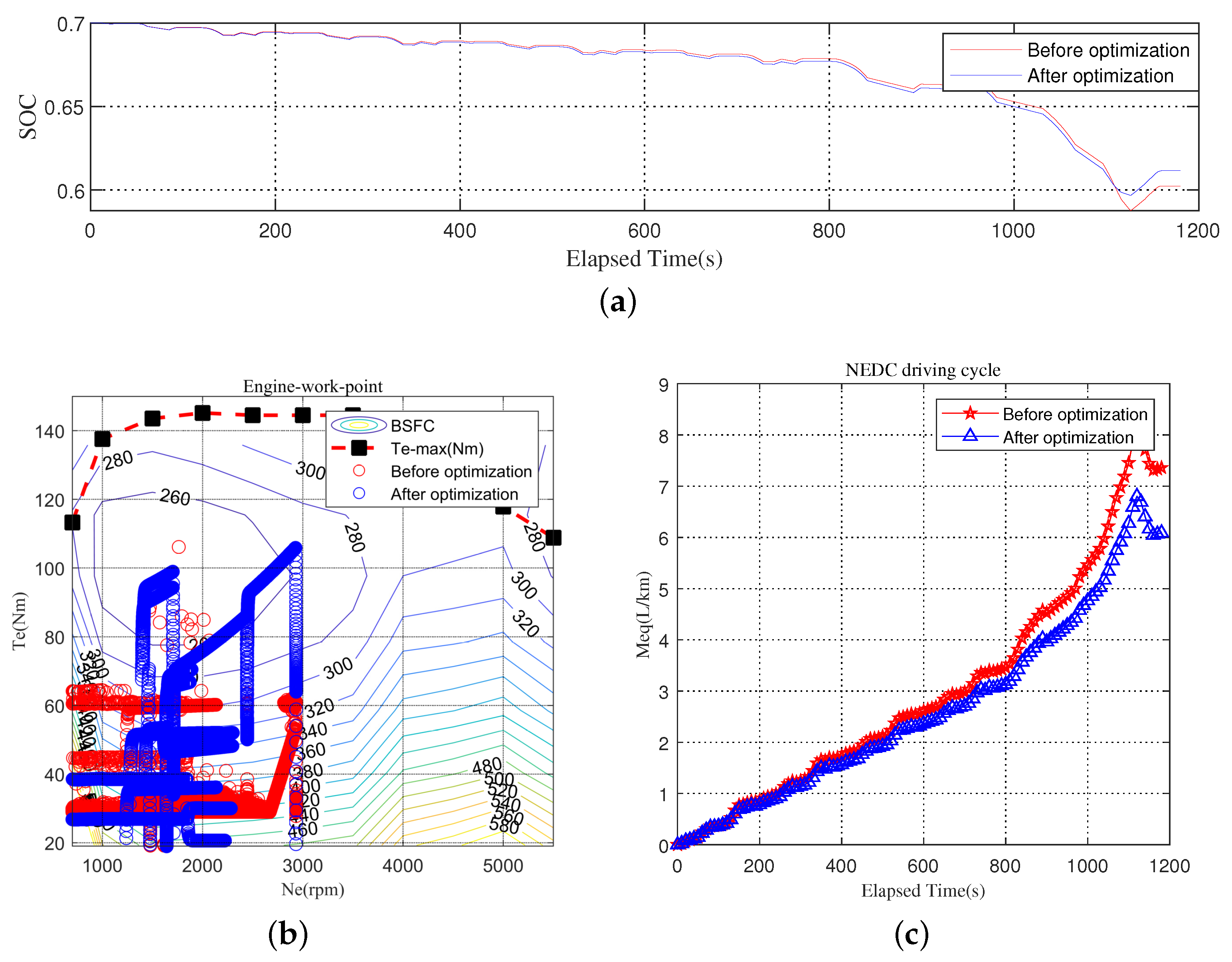
5.3. Optimization of Based on DPSO-GA
6. Conclusions
Author Contributions
Funding
Conflicts of Interest
References
- Qin, Y.; Tang, X.; Jia, T.; Duan, Z.; Zhang, J.; Li, Y.; Zheng, L. Noise and vibration suppression in hybrid electric vehicles: State of the art and challenges. Renew. Sustain. Energy Rev. 2020, 124, 109782. [Google Scholar] [CrossRef]
- Tang, X.; Hu, X.; Yang, W.; Yu, H. Novel torsional vibration modeling and assessment of a power-split hybrid electric vehicle equipped with a dual mass flywheel. IEEE Trans. Veh. Technol. 2018, 67, 1990–2000. [Google Scholar] [CrossRef]
- Wilberforce, T.; El-Hassan, Z.; Khatib, F.N.; Al Makky, A.; Baroutaji, A.; Carton, J.G.; Olabi, A.G. Developments of electric cars and fuel cell hydrogen electric cars. Int. J. Hydrog. Energy 2017, 42, 25695–25734. [Google Scholar] [CrossRef] [Green Version]
- Xie, S.; Hu, X.; Liu, T.; Qi, S.; Lang, K.; Li, H. Predictive vehicle-following power management for plug-in hybrid electric vehicles. Energy 2019, 166, 701–714. [Google Scholar] [CrossRef]
- Shi, D.; Wang, S.; Cai, Y.; Chen, L. Stochastic predictive energy management of power split hybrid electric bus for real-world driving cycles. IEEE Access 2018, 6, 61700–61713. [Google Scholar] [CrossRef]
- Sun, X.; Diao, K.; Yang, Z.; Lei, G.; Guo, Y.; Zhu, J. Direct torque control based on a fast modeling method for a segmented-rotor switched reluctance motor in HEV application. IEEE J. Emerg. Sel. Top. Power Electron. 2019, 99, 1. [Google Scholar] [CrossRef]
- Xu, N.; Kong, Y.; Chu, L.; Ju, H.; Yang, Z.; Xu, Z.; Xu, Z. Towards a smarter energy management system for hybrid vehicles: A comprehensive review of control strategies. Appl. Sci. 2019, 9, 2026. [Google Scholar] [CrossRef] [Green Version]
- Liang, J.; Li, Y.; Jia, W.; Lin, W.; Ma, T. Comparison of Two Energy Management Strategies Considering Power System Durability for PEMFC-LIB Hybrid Logistics Vehicle. Energies 2021, 14, 3262. [Google Scholar] [CrossRef]
- Zhou, H.; Xu, Z.; Liu, L.; Liu, D.; Zhang, L. A rule-based energy management strategy based on dynamic programming for hydraulic hybrid vehicles. Math. Probl. Eng. 2018, 2018, 10. [Google Scholar] [CrossRef] [Green Version]
- Tang, X.; Yang, W.; Hu, X.; Zhang, D. A novel simplified model for torsional vibration analysis of a series-parallel hybrid electric vehicle. Mech. Syst. Sig. Process 2017, 85, 329–338. [Google Scholar] [CrossRef]
- Jiang, Q.; Ossart, F.; Marchand, C. Comparative study of real-time HEV energy management strategies. IEEE Trans. Veh. Technol. 2017, 66, 10875–10888. [Google Scholar] [CrossRef] [Green Version]
- Ali, A.M.; S€offker, D. Towards optimal power management of hybrid electric vehicles in real-time: A review on methods, challenges, and state-of-the-art solutions. Energies 2018, 11, 476. [Google Scholar] [CrossRef] [Green Version]
- Zhuang, W.; Zhang, X.; Li, D.; Wang, L.; Yin, G. Mode shift map design and integrated energy management control of a multi-mode hybrid electric vehicle. Appl. Energy 2017, 204, 476–488. [Google Scholar] [CrossRef]
- Pérez, L.V.; Bossio, G.R.; Moitre, D.; García, G.O. Optimization of power management in a hybrid electric vehicle using dynamic programming. Math. Comput. Simul. 2006, 73, 244–254. [Google Scholar] [CrossRef]
- Sun, X.; Hu, C.; Zhu, J.; Wang, S.; Zhou, W.; Yang, Z.; Guo, Y. MPTC for PMSMs of EVs with multi-motor driven system considering optimal energy allocation. IEEE Trans. Magn. 2019, 55, 8104306. [Google Scholar] [CrossRef]
- Li, L.; Yang, C.; Zhang, Y.; Zhang, L.; Song, J. Correctional DP-based energy management strategy of plug-in hybrid electric bus for city-bus route. IEEE Trans. Veh. Technol. 2015, 64, 2792–2803. [Google Scholar] [CrossRef]
- Peng, H.; Li, J.; Deng, K.; Thul, A.; Li, W.; Lowenstein, L.; Sauer, D.U.; Hameyer, K. An Efficient Optimum Energy Management Strategy Using Parallel Dynamic Programming for a Hybrid Train Powered by Fuel-Cells and Batteries. In Proceedings of the 2019 IEEE Vehicle Power and Propulsion Conference (VPPC), Hanoi, Vietnam, 14–17 October 2019; pp. 1–7. [Google Scholar]
- Du, G.; Zou, Y.; Zhang, X.; Liu, T.; Wu, J.; He, D. Deep reinforcement learning based energy management for a hybrid electric vehicle. Energy 2020, 201, 117591. [Google Scholar] [CrossRef]
- Ferrario, A.M.; Manzano, F.S.; Bocci, E. Hydrogen vs. Battery in the Long-term Operation. A Comparative Between Energy Management Strategies for Hybrid Renewable Microgrids. IEEE Consum. Electron. Mag. 2020, 9, 1–28. [Google Scholar]
- Yao, Z.; Wang, Y.; Liu, B.; Zhao, B.; Jiang, Y. Fuel consumption and transportation emissions evaluation of mixed traffic flow with connected automated vehicles and human-driven vehicles on expressway. Energy 2021, 230, 120766. [Google Scholar] [CrossRef]
- Paganelli, G. Conception et Commande d’une Chaîne de Traction pour Véhicule Hybride Parallèle Thermique et électrique. Ph.D. Thesis, Hauts-de-France Polytechnic University, Valenciennes, France, 1999. [Google Scholar]
- Geng, B.; Mills, J.K.; Sun, D. Energy management control of micro turbine-powered plug-in hybrid electric vehicles using the telemetry equivalent consumption minimization strategy. IEEE Trans. Veh. Technol. 2011, 60, 4238–4248. [Google Scholar] [CrossRef]
- Gao, A.; Deng, X.; Zhang, M. Design and validation of real-time optimal control with ECMS to minimize energy consumption for parallel hybrid electric vehicles. Math. Probl. Eng. 2017, 2017, 1–13. [Google Scholar] [CrossRef] [Green Version]
- Hou, C.; Ouyang, M.; Xu, L.; Wang, H. Approximate Pontryagin’s minimum principle applied to the energy management of plug-in hybrid electric vehicles. Appl. Energy 2014, 115, 174–189. [Google Scholar] [CrossRef]
- Rezaei, A.; Burl, J.; Zhou, B. Estimation of the ECMS equivalent factor bounds for hybrid electric vehicles. IEEE Trans. Control Syst. Technol. 2018, 26, 2198–2205. [Google Scholar] [CrossRef]
- Guo, S.; Dang, C.; Liao, X. Joint opportunistic power and rate allocation for wireless ad hoc networks: An adaptive particle swarm optimization approach. J. Netw. Comput. Appl. 2011, 34, 1353–1365. [Google Scholar] [CrossRef]
- Alfi, A.; Modares, H. System identification and control using adaptive particle swarm optimization. Appl. Math. Model 2011, 35, 1210–1221. [Google Scholar] [CrossRef]
- Wu, X.; Cao, B.; Wen, J.; Bian, Y. Particle swarm optimization for plug-in hybrid electric vehicle control strategy parameter. In Proceedings of the IEEE Vehicle Power and Propulsion Conference, Harbin, China, 3–5 September 2008. [Google Scholar]
- Chen, Z.; Xiong, R.; Cao, J. Particle swarm optimization-based optimal power management of plug-in hybrid electric vehicles considering uncertain driving conditions. Energy 2016, 96, 197–208. [Google Scholar] [CrossRef]
- Wang, Y.; Wang, X.; Sun, Y.; You, S. Model predictive control strategy for energy optimization of series-parallel hybrid electric vehicle. J. Clean. Prod. 2018, 199, 348–358. [Google Scholar] [CrossRef]
- Chen, S.Y.; Wu, C.H.; Hung, Y.H. Optimal Strategies of Energy Management Integrated with Transmission Control for a Hybrid Electric Vehicle using Dynamic Particle Swarm Optimization. Energy 2018, 160, 154–170. [Google Scholar] [CrossRef]
- Hwang, H.-Y.; Chen, J.-S. Optimized Fuel Economy Control of Power-Split Hybrid Electric Vehicle with Particle Swarm Optimization. Energies 2020, 13, 2278. [Google Scholar] [CrossRef]
- Ferrario, A.M.; Bartolini, A.; Manzano, F.S. A model-based parametric and optimal sizing of a battery/hydrogen storage of a real hybrid microgrid supplying a residential load: Towards island operation. Adv. Appl. Energy 2021, 3, 100048. [Google Scholar] [CrossRef]
- Tian, X.; He, R.; Sun, X.; Cai, Y.; Xu, Y. An ANFIS-based ECMS for Energy Optimization of Parallel Hybrid Electric Bus. IEEE Trans. Veh. Technol. 2019, 69, 1473–1483. [Google Scholar] [CrossRef]
- Xie, S.; Hu, X.; Xin, Z.; Brighton, J. Pontryagin’s minimum principle based model predictive control of energy management for a plug-in hybrid electric bus. Appl. Energy 2019, 236, 893–905. [Google Scholar] [CrossRef] [Green Version]
- Lin, X.; Feng, Q.; Mo, L.; Li, H. Optimal adaptation equivalent factor of energy management strategy for plug-in CVT HEV. Proc. Inst. Mech. Eng. Part D J. Automob. Eng. 2019, 233, 877–889. [Google Scholar] [CrossRef]
- Lei, Z.; Qin, D.; Hou, L.; Peng, J.; Liu, Y.; Chen, Z. An adaptive equivalent consumption minimization strategy for plug-in hybrid electric vehicles based on traffic information. Energy 2020, 190, 116409. [Google Scholar] [CrossRef]
- Assareh, E.; Behrang, M.A.; Assari, M.R.; Ghanbarzadeh, A. Application of PSO (particle swarm optimization) and GA (genetic algorithm) techniques on demand estimation of oil in Iran. Energy 2010, 35, 5223–5229. [Google Scholar] [CrossRef]
- Song, Z.; Wu, G.; Zheng, S. Multi-objective optimization of energy management strategy of plug-in hybrid electric vehicle. J. Tongji Univ. 2011, 39, 99–103. [Google Scholar]
- Guo, Q.; Zhao, Z.; Shen, P.; Zhan, X.; Li, J. Adaptive optimal control based on driving style recognition for plug-in hybrid electric vehicle. Energy 2019, 186, 115824. [Google Scholar] [CrossRef]


| Operation Mode | Conditions | Torque Distribution |
|---|---|---|
| 1. Stop mode | ||
| 2. Motor-only mode | ||
| 3. Engine-only mode | ||
| 4. Hybrid mode | ||
| 5. Recharging mode | ||
| 6. Regenerative braking mode | ||
| Component | Parameters | Value |
|---|---|---|
| Engine | Engine type | 1.9L.SI |
| Maximum Power | 63 kW @ 5500 rpm. | |
| Peak Torque | 145 Nm @ 2000 rpm. | |
| Motor | Motor type | Permanent magnet motor |
| Maximum power | 25 kW | |
| Battery | Battery type | Lithium–ion |
| Capacity | 25 Ah | |
| Vehicle | Vehicle mass | 1350 kg |
| Radius of tire | 0.282 m | |
| Vehicle front area | 2 m | |
| Rolling resistance coefficient | 0.014 | |
| Aerodynamic drag coefficient | 0.335 |
| Strategy | (L/km) | (L/km) | Improved(%) |
|---|---|---|---|
| Rule-EMS | 8.387 | 6.037 | 0 |
| Basic-ECMS | 7.144 | 4.793 | 17.40 |
| PSO-ECMS | 7.088 | 4.734 | 18.32 |
| Approximate-ECMS | 7.135 | 4.787 | 17.55 |
| (L/km) | (L/km) | Improved | |||
|---|---|---|---|---|---|
| Before optimization | 2.75 | 7.135 | 4.787 | 0.0541 | 0 |
| After optimization | 3.10 | 6.499 | 4.354 | 0.1205 | 9.04% |
Publisher’s Note: MDPI stays neutral with regard to jurisdictional claims in published maps and institutional affiliations. |
© 2021 by the authors. Licensee MDPI, Basel, Switzerland. This article is an open access article distributed under the terms and conditions of the Creative Commons Attribution (CC BY) license (https://creativecommons.org/licenses/by/4.0/).
Share and Cite
Qiang, P.; Wu, P.; Pan, T.; Zang, H. Real-Time Approximate Equivalent Consumption Minimization Strategy Based on the Single-Shaft Parallel Hybrid Powertrain. Energies 2021, 14, 7919. https://doi.org/10.3390/en14237919
Qiang P, Wu P, Pan T, Zang H. Real-Time Approximate Equivalent Consumption Minimization Strategy Based on the Single-Shaft Parallel Hybrid Powertrain. Energies. 2021; 14(23):7919. https://doi.org/10.3390/en14237919
Chicago/Turabian StyleQiang, Penghui, Peng Wu, Tao Pan, and Huaiquan Zang. 2021. "Real-Time Approximate Equivalent Consumption Minimization Strategy Based on the Single-Shaft Parallel Hybrid Powertrain" Energies 14, no. 23: 7919. https://doi.org/10.3390/en14237919
APA StyleQiang, P., Wu, P., Pan, T., & Zang, H. (2021). Real-Time Approximate Equivalent Consumption Minimization Strategy Based on the Single-Shaft Parallel Hybrid Powertrain. Energies, 14(23), 7919. https://doi.org/10.3390/en14237919