1. Introduction
Superconductors have a very large current-carrying capability, which enables superconducting machines to be potentially competitive in areas where high power density is required, e.g., electric aircraft, wind energy, maglev train, ship propulsion. The advantages of using superconductors to obtain high power density have been successfully proved by different demonstrations and studies, for instance, the EcoSwing project, which has designed and tested a full-scale direct-drive high-temperature-superconducting wind turbine generator in the real field under practical wind conditions [
1,
2,
3]. That project proved that, by using high-temperature superconductors in the rotor, a wind generator can achieve a 24% weight reduction with a torque density of 40 Nm/kg compared to a permanent magnet counterpart. If the superconductors are used in the rotor, by supplying the maximum allowable current to the superconducting field winding for a given dimension within the limit of the critical current and cooling power, the magnetic loading can be higher. In order to further benefit from superconductors, there is a trend to employ superconductors in the stator to replace AC copper windings as well. By pushing the operating current inside the superconductors to the maximum allowable current in the stator coils, the electrical loading can be significantly increased. It has been estimated that fully superconducting wind generators have the potential to increase the torque density to over 160 Nm/kg [
4,
5]. However, when the superconductors are exposed to AC magnetic field or current, energy dissipation occurs. If superconductors are used in the stator AC coils, they not only carry AC transport current themselves, but also experience AC magnetic field. The challenge of the AC superconducting stator coils is whether the AC loss is within an acceptable range, which is essential for the generator design. So far, a few papers in the literature have addressed the integration of the estimation of the AC loss in the design process of the superconducting generators. The reason of the limited number of works is the complexity of AC loss calculation in the generator [
6,
7,
8,
9,
10]. Most of the papers mentioned above analyzed the AC loss of the stator coils analytically, where the hysteresis loss and transport current loss are calculated independently for a rough estimation. For example, in [
9], the AC loss of the superconductors was calculated by using the perpendicular magnetic field to superconducting tapes in an approximate magnetization formula, which was measured using a saddle-shaped pickup coil. A more accurate estimation was made by [
10] which decoupled the machine model and AC loss model by simulating the magnetic field maps of the whole motor domain with commercial finite-element program and then the field maps were exported and used as non-uniform applied magnetic field for a separate program based on the minimum electro-magnetic entropy production (MEMEP) to calculate AC loss.
In order to investigate the potential of the fully superconducting wind generators, it is important to integrate the accurate AC loss estimation with the electromagnetic design. Since there are many parameters influencing the generator design, changing one parameter at the time makes the design process a time-consuming and challenging task. Hence, in this paper, an in-house code was developed to design superconducting wind generators, taking into account geometry, electromagnetics, superconducting properties, iron properties, and AC loss. The estimation of the AC loss is made through the
T–A formulation of Maxwell’s equations by employing finite elements within the whole generator domain [
11,
12,
13,
14]. This work addresses the design of a 10 MW fully superconducting direct-drive wind generator to present the model and is organized as follows. The proposed modelling approach is described in
Section 2, followed by detailed design results and analysis in
Section 3. In
Section 4 the AC loss of the stator coils are discussed. Then all the results and findings are summarized in
Section 5.
2. Machine Model
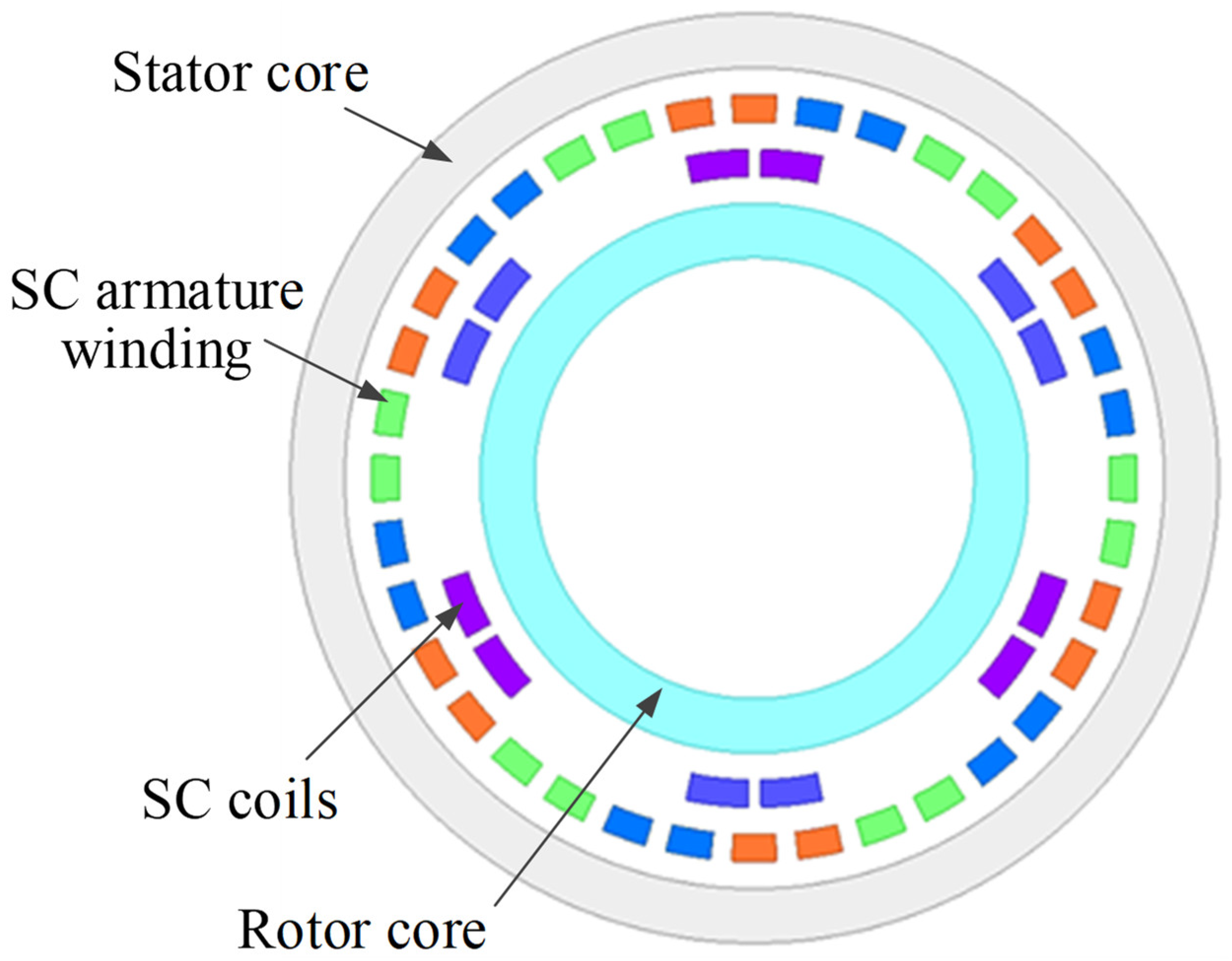
The structure of the generator is illustrated in
Figure 1. It is a radial flux synchronous machine with air-gap windings. The stator coils are three-phase distributed windings to reduce the harmonics to rotor coils. For simplification, the stator coils are whole-pitch windings. Both the stator and rotor core are made of iron at room temperature. The amplitude of the flux density in the stator and rotor iron core is set to be 2 T. The working temperatures of the stator and rotor superconducting coils are different and the rotor coils is cooled down to 30 K. The output power and rotational speed of the generator are 10 MW and 10 rpm, respectively. The main design variables are the air-gap diameter, the pole pair number and the working temperature of the stator coils.
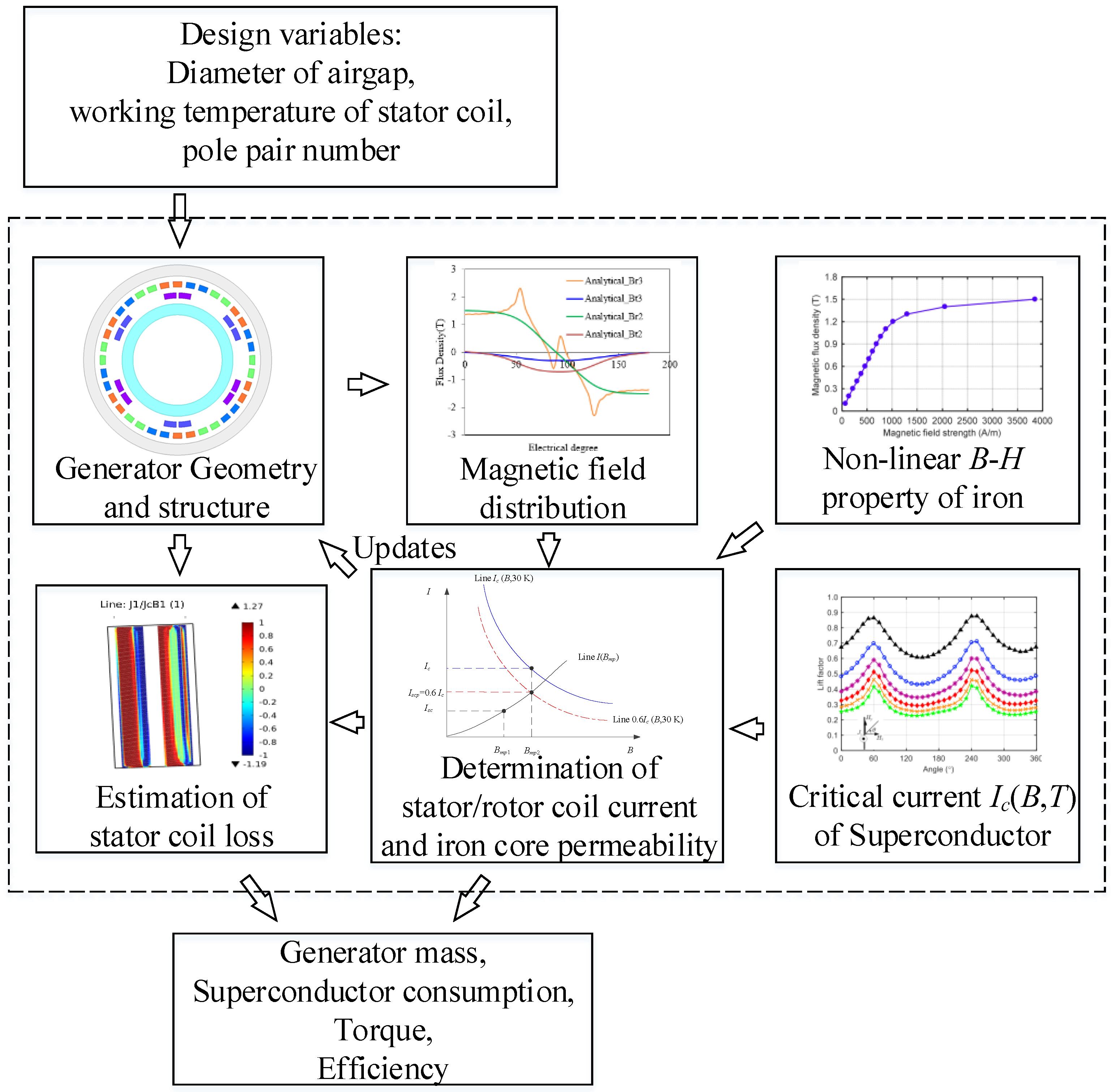
The general procedure of the design model is presented in
Figure 2. The first part is to calculate the generator structure and geometry. This geometry data provides all the necessary input for the calculation of the magnetic flux density distribution. The main part of the design model is the determination of the working points: the working current of stator and rotor coils, the working permeability of the stator and rotor iron. The non-linear magnetic property of iron (
B–H) and superconducting property of
Ic(
B,
T) are basic inputs for this determination. Since the permeability of the iron and the critical current of the superconductors are both a function of flux density, the four working points above influence each other and cannot be determined independently. This issue will be addressed in
Section 2.3. Moreover, there is a constraint of amplitude of flux density in the iron cores: the thickness of the stator and rotor iron core needs modification after the determination of the working points. Then the updated geometry parameters, the stator and rotor working current are used to estimate the AC loss of the stator coils through COMSOL Multiphysics. In addition to the combined effect of AC transport current and AC magnetic field, the finite number of turns, the non-uniform and non-sinusoidal magnetic field and the corresponding critical current density which is field-dependent makes the development of analytical expressions to calculate AC loss extremely difficult. Finally, the generator active material weight, superconductor consumptions, torque and efficiency are computed.
The model is based on a 2D representation of a generator. This means that the end effects are not considered. Moreover, in the magnetic field calculation, superposition is applicable to include both the fields from the stator and rotor coils.
2.1. Generator Geometry
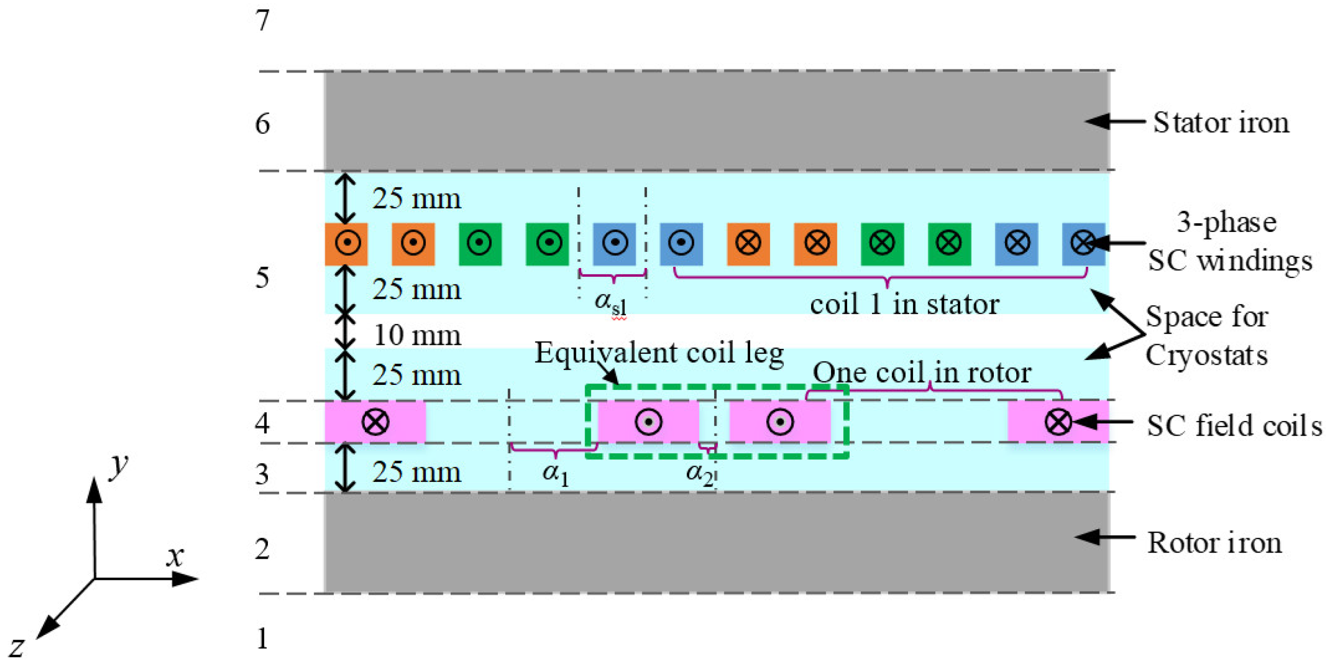
In the generator geometry, the physical air-gap length is 10 mm. In order to have enough space for the cryogenic cooling system, the space between the superconducting coils and the iron cores, and the space between the superconducting coils and the air gap are 25 mm in radial direction, as illustrated in
Figure 3. In the stator, even though there is no physical slot, the space of one leg of the superconducting coils is assumed to be one virtual slot. To take into account the cooling and mechanical supports, the ratio of the slot width to the slot pitch is 0.5. Because the higher the AC current, the higher the AC loss, the operation margin for the stator coils is made larger. Here in the paper, we choose the operating AC current of the stator coils equal to 0.55 of the critical current. As for the rotor coils, the operating DC current is 0.75 of the critical current. These three ratios are kept fixed when different design variables are used for the 10 MW superconducting generator.
In the stator winding, there are no parallel tapes in one turn and no parallel branches in one phase. When the transport current is set to a particular fraction of the critical current, for example 0.55 as mentioned above, the phase current and phase voltage are not the same for different designs. The reason is that the critical current of the superconducting coils in the stator is determined by the temperature and the magnetic field’s amplitude and orientation and they are different from case to case. Similarly, the magnetic loading of different designs is not the same either, due to the fixed ratio of the operating current to critical current. What we want to find out is the maximum output power per meter within the given geometry and settings, which indicates the potential that a given configuration can achieve. The output power of 10 MW requirement is met through the modification of axial stack length.
2.2. Calculation of Magnetic Field Distribution
To find the operating currents and estimate the torque, it is important to know the magnetic field in the whole cross section of the generator, as shown in
Figure 1. The magnetic field is generated by the stator and rotor coils together.
Figure 3 illustrates one pole pair of the generator. Since the two adjacent coil legs in different coils in the same pole pair have the same current direction, we can treat the rotor coils as one equivalent coil with current in and out of the paper (
z-direction). One of the equivalent coil legs is shown in
Figure 3. This equivalent coil has a period of one pole pair. In the stator, the coils come from different phases. Each coil has two coil legs with current in and out of the paper and has a period of one pole pair. The difference of the coils in the stator is the supplied current and the space angle. Hence, the magnetic field generated by the stator and rotor coils in one period is the superposition of the magnetic fields generated by all the stator coils and the equivalent rotor coil. Then the calculation of the whole field is simplified by solving the problem of the magnetic field produced by one coil. The superconducting coils in the rotor are taken as an example. To calculate the magnetic field, the Poisson and Laplace equations are employed based on the magnetic vector potential
φ, which has only the
z- direction component [
15,
16]. In region 4 where the superconducting coils are located, as shown in
Figure 3, the governing equation in cylindrical coordinates is expressed as
where
r is the radius,
θ is the azimuthal angle,
Jscz is the circumferential current density of the superconducting winding in the rotor,
φz4 is the magnetic vector potential of region 4, and
μ0 is the permeability of the vacuum, which is 4π × 10
−7 H/m.
The governing equation of the other regions is expressed as
where
m is the number of region, which equals to 1, 2, 3, 5, 6, 7; and
φzm is the magnetic vector potential of region
m.
As the
z-direction component of magnetic vector potential
φz in the generator is generated by the current density distribution of the superconducting coils
Jscz, the general solutions of Equations (1) and (2) are
where
n is the harmonic order;
t is an integer, which is 1,2,3…;
p is the pole pair number;
Anm and
Cnm are coefficients to express
φz due to the
nth harmonic in region
m, and they are calculated through boundary conditions, which are given in [
17];
ke is the current density in the specific area, which is expressed as
where
jsc is the transient current density in the rotor superconducting coils,
α1 and
α2 are the half angle between two adjacent coil legs and the half inner angle of one rotor coil, respectively.
The procedure to calculate the flux density generated by one stator coil is the same as for the superconducting coils in the rotor, except that sin(
npθ) is replaced by sin[
np(
θ-
β)] and
ke is replaced by
keaj as follows:
where
αsl is the slot spreading angle as illustrated in
Figure 3,
β is the mechanical angle shifting from coil 1 in stator,
ja is the transient current density in the coil. Please note that the starting angle in Equation (4) is the middle of the studied coil. When the superposition is used, we need calculate the coils to the same starting angle, which can be achieved by changing the calculation range of
θ for each coil.
2.3. Determination of Operating Points
One important part in the design is to find the operating currents of the stator and rotor coils, which determine the electrical and magnetic loadings. The operating current in the stator coils is the amplitude of the phase current. In this work, the operating currents of the superconducting coils are calculated based on the load-line method, which needs the function of supplied currents and applied magnetic field of the studied coil in the generator (the so-called load line) and the characterization data (critical current as a function of temperature, magnetic field and angle of magnetic field) of the superconductors as inputs. The elliptical equation for the lift factors which are used to describe the characterization data of superconductors is expressed in Equation (7). The fitted parameters at different temperatures of the measured lift factors from SuperPower Inc. are taken from [
13,
18] as listed in
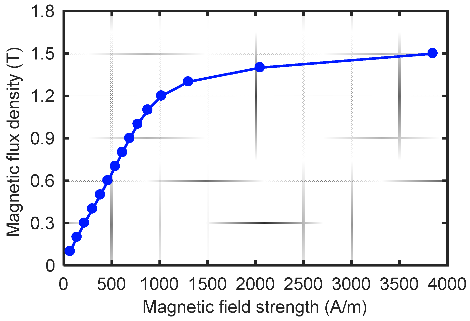
Table 1. To get more accurate flux density, the nonlinearity of magnetic property of the stator and rotor iron core are taken into account and the function of magnetic strength and flux density of ferromagnetic materials (
B–H) [
17] are included as in
Figure 4. For the magnetic field outside the given curve, a linear extrapolation is used.
As mentioned above, the determinations of the operating currents in the stator and rotor coils,
Iam and
Isc, and of the operating relative permeability of the stator and rotor core,
us and
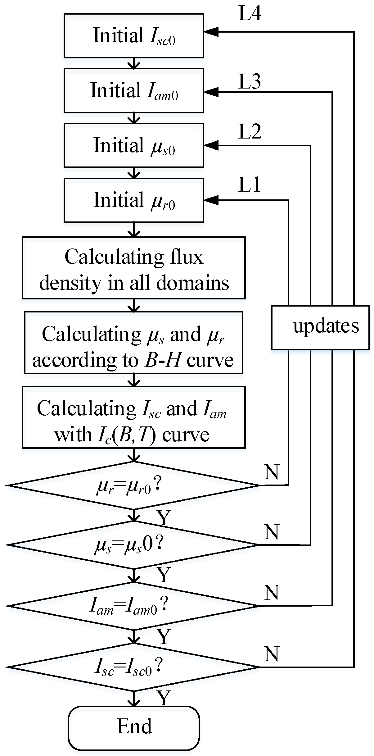
ur, are not independent, since they vary with the magnetic field. In this work, an iterative algorithm is proposed, as shown in
Figure 5. First, initial values of operating currents and relative permeability are given as input. Then the flux density in all domains is calculated. According to the magnetic flux density in the stator and rotor core, and the magnetic property of the iron, i.e., the
B–H curve, new values for the relative permeability of the stator and rotor core,
us and
ur, can be obtained. The load line is expressed by using the maximum flux density in the studied stator and rotor coils and initial currents. According to the load line and the characterization data of
Ic(
B,
T), a new supplied current
Iam,
Isc is found. Here in order to make a safe design, the
Ic(
B,
T) we use is the critical current with a magnetic field perpendicular to the wide face of the superconducting tape. After that, the new values
ur,
us,
Iam,
Isc are compared to the initial values
ur0,
us0,
Iam0,
Isc0, respectively. If the two compared values are not equal (within a tolerance of 2%), the initial values will be updated and the corresponding loops will be repeated until all the compared values meet the tolerance requirements.
There are three factors that make the determination process complex:
Since the relative permeabilities in the stator and rotor core us and ur have a spatial distribution in one pole pair, the operating relative permeability needs to be searched at each calculated mechanical angle.
Since the current in the stator coils is AC and has a temporal distribution, the operating currents of the stator and rotor coils Iam, Isc should be calculated at each time instant in one period. The smallest current within this period is the final operating current we need.
The maximum flux density in the stator and rotor core is limited to 2 T, which is reached by changing the height of the stator rotor core in the geometry according to the magnetic field. Correspondingly, the modification of the geometry will lead to new start of the determination of the operating points.
Once the operating points are determined, the torque per meter
Te of the generator is calculated as [
19]
where
ψm is the flux linkage per meter produced by the superconducting coils in one pole of the rotor,
Ld and
Lq are the
d-axis and
q-axis inductance of the stator coils,
id and
iq are the
d-axis and
q-axis currents of the stator coils. Another option to calculate
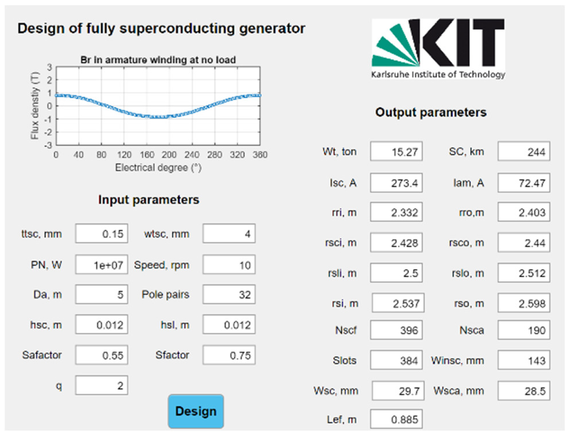
Te accurately is to use the stress tensor, which is not used in our work, because Equation (8) is simpler and has a good accuracy (around 15% compared with finite element software). The axial stack length of the generator is chosen to meet the output torque of the generator. Correspondingly, the active material weight and superconductor length used in the generator is calculated. The analytical model mentioned above to design a fully superconducting generator has been programmed in MATLAB and the user interface is presented in
Figure 6.
2.4. Estimation of AC Loss
The analytical expressions of the energy loss of infinite stacks of thin superconducting tapes, as a function of transport AC current or applied AC magnetic field, were derived [
20]. However, there were limitations on the application of the analytical equations to the superconducting machines. In regard to the superconducting coils in the stator, the superconductors carried the AC transport currents while, simultaneously, the AC magnetic field was applied to them. This process is different with the case of the AC applied field or AC current from analytical methods, in which the AC transport current and AC applied field are independent from each other, and the interacting influence of the two cases on the AC loss is not included. Even though the analytical expressions of a single tape were developed for this combined case of AC current and AC field [
21], they were not applicable to the superconducting coils in the generator. One reason for this is that the superconducting coils in the generator had a finite number of turns, instead of single turn or infinite turns. Another reason is that, unlike in [
20] and [
21], the AC field on the superconducting coils was neither uniform nor sinusoidal. This made the distribution of the critical current density not only non-uniform in one tape but also different from tape to tape in the superconducting coils, since the critical current density depended on the magnetic field. As a result, there was no analytical formula for the superconducting coils in a generator. Hence, in order to evaluate the AC loss of the stator coils, the
T–A formulation of Maxwell’s equations implemented in COMSOL Multiphysics in 2D [
14] was employed in the generator design obtained from the analytical model described above.
3. Design Results and Analysis
The model described above is used to design a 10 MW fully superconducting direct-drive wind generator with a rotational speed of 10 rpm. The width of the superconducting tapes is 4 mm and their thickness is 0.15 mm. The working temperature of the stator coils at 65 K is used as an example. The air-gap diameter Da varies from 4 m to 6 m, and the pole pair number changes from 12 to 40. One double pancake coil is employed in a stator virtual slot or a rotor pole.
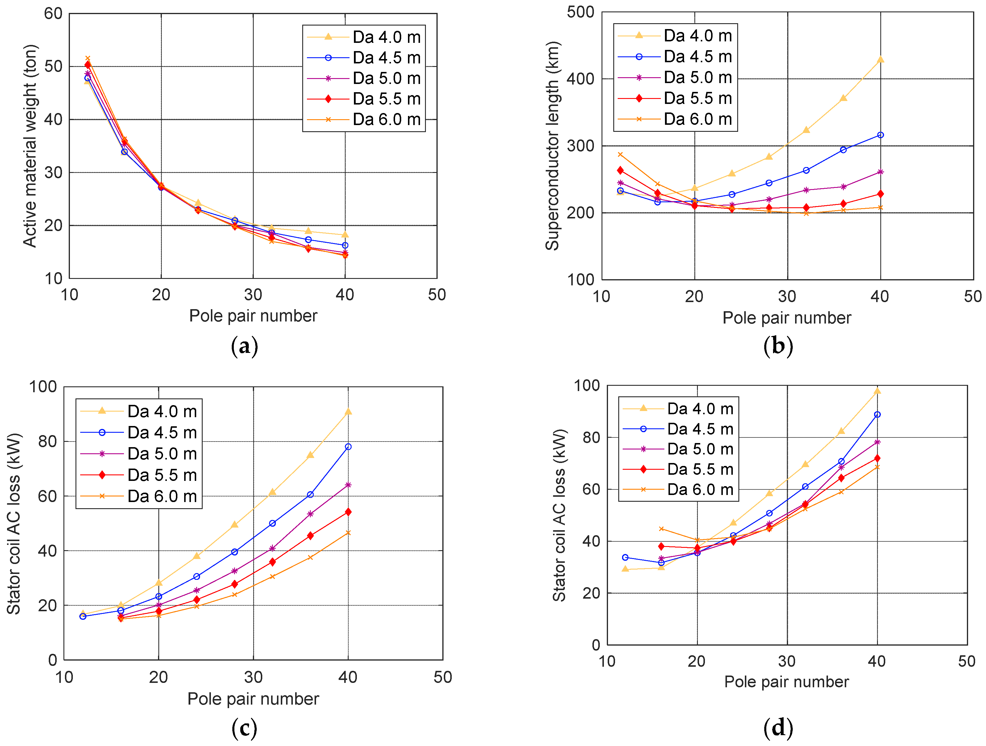
The active weight, superconductor length, and AC loss of the stator coils of the designed superconducting generator as a function of air-gap diameter and pole pair number are illustrated in
Figure 7. The weight of the active materials (the superconductors and iron materials in the generator) decreases with increased pole pair number mainly due to the reduction of the stator and rotor core height. At lower pole pair numbers, the used superconductor length decreases with increased pole pair numbers mainly due to the reduction of the end windings. At higher pole pair numbers, the superconductor length grows with the increased pole pair number. This is mainly due to the increase of the axial stack length and the number of coils. The AC loss of the stator coils increases with the pole pair number, mainly because the electric frequency of the AC current and the number of the coils are higher.
When the air gap diameter increases, the amount of end windings increases and there is space for more turns of superconductors in the cross section, which leads to higher magnetic loading and electric loading. This is an advantage for the active material weight, since the axial stack length is decreased. However, higher magnetic field will lead to larger heights of rotor and stator iron core, as the maximum flux density in the iron core is kept the same. Correspondingly, the disadvantages coming from the increase of the rotor and stator core height and the increase of end windings are approximately compensated by the decrease of the axial length in terms of active material weight. When it comes to the superconductor length, the increase of superconductor turns and end windings and the decrease of the stack axial length make the superconductor length grow first and then drop with the increase of air-gap diameter. Even though the loss of a single stator coil is higher at larger air gap diameter due to more turns, the axial stack length is smaller. As a result, the total AC loss is lower when there are no end effects. When we assumed the same loss distribution of the cross-section perpendicular to the current direction in the end windings as in the straight part of the coil, the AC loss including the contribution of the end windings is illustrated in
Figure 7d, which displayed similar trends to the superconductor length, due to the influence of the amount of superconductors in the straight part, end windings, axial stack length, as well as electric frequency.
The smallest superconductor length is around 200 km for all designs. Further reduction of the superconductor length can be made by employing iron poles and teeth, and optimizing the cryogenic cooling system to reduce the equivalent air gap length.
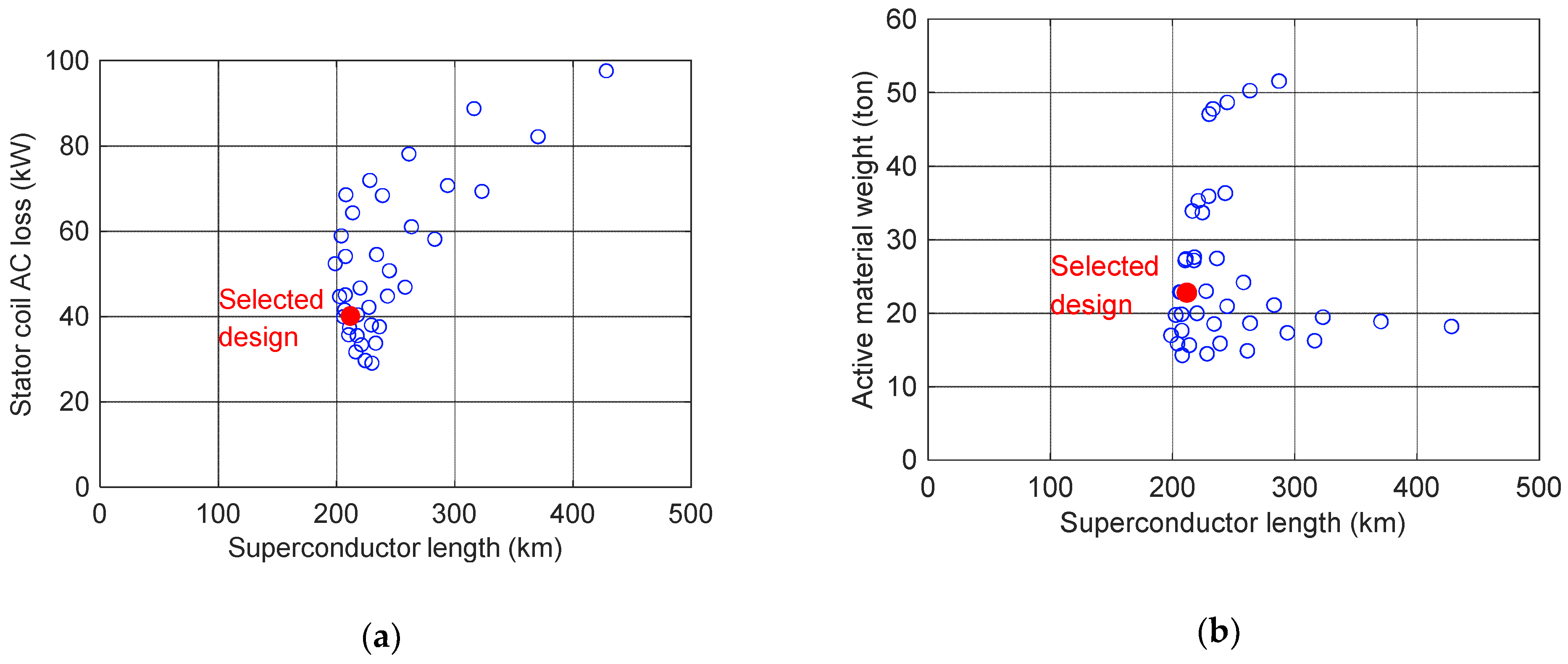
To find the design with better performance, all the designed active material weight, superconductor length and the AC loss of stator coils are plotted in
Figure 8. When the stator AC loss reaches the lowest, the active material weight and the superconductor length are not the smallest. In fact, it is impossible to locate a design which has the lowest weight, lowest stator AC loss and smallest superconductor length at the same time. Our aim is then to find a design with lower stator AC loss, shorter superconductor lengths and smaller weight, which is indicated by the red circles. The corresponding parameters are listed in
Table 2. The stator AC loss here includes the end windings. In this configuration, the AC loss of all the stator coils at rated current is 28.9 kW/m.
4. Impact Factors of AC Loss of Stator Coils
4.1. Influence of the Width of Superconducting Tapes
A common way to reduce the AC loss is to employ narrower superconducting tapes. In [
13] the AC loss of stator coils reduced from 28 kW to 15.42 kW by changing the superconductor tapes from 4 mm to 2 mm. However, in our case, if we keep the distance between the pancake coils in a slot 2 mm, and use the same lift factors and half the critical current of the 4 mm tape, the total loss of the stator coils is 29.4 kW/m as shown in
Table 3. The coil number in one slot is labelled as 1st, 2nd, 3rd and 4th from left to right (from rotor side to stator core). Compared with the 4 mm, the AC loss of the stator coils is not decreased. A possible explanation is as follows. In our design as little iron material as possible is used to reach an ultra-light superconducting generator and there are no iron teeth surrounding the superconducting coils. Moreover, the distance of the iron core to the superconducting coils is 25 mm. Hence, the superconducting coils in the studied slot are subjected to magnetic fields from the rotor coils, coils from other slots, and coils from the same slot, that is self-field. In [
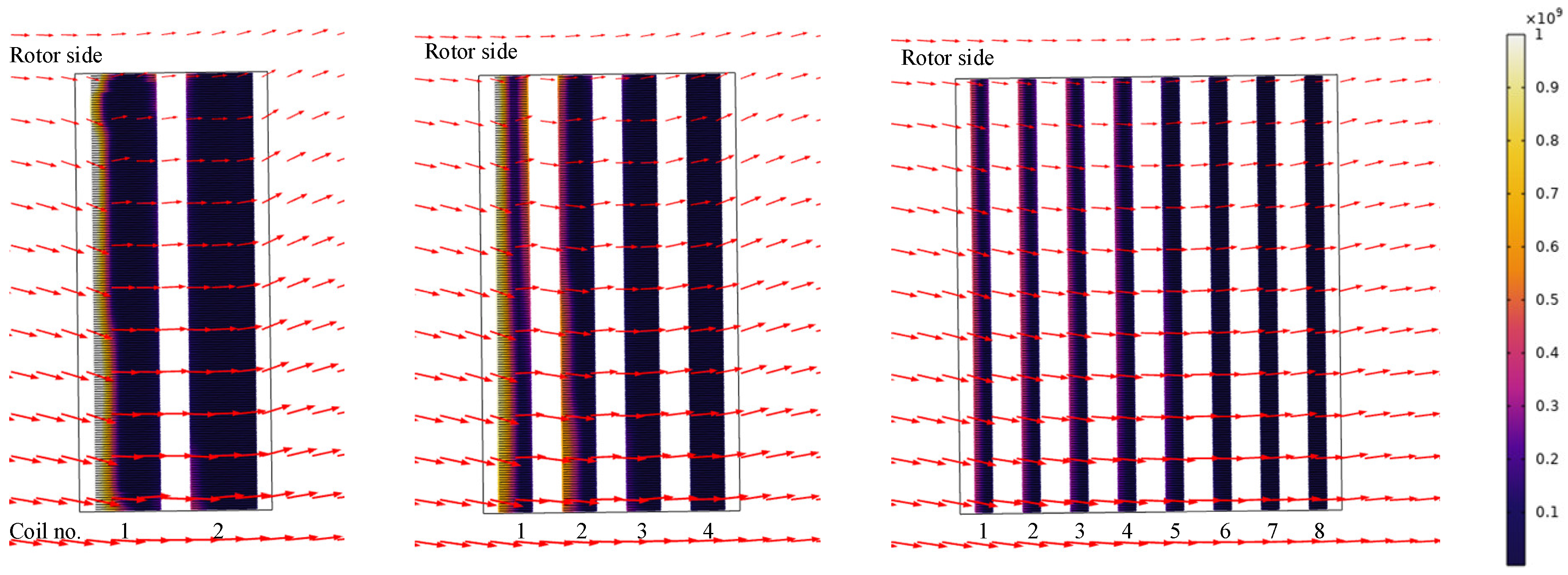
13] there is a large space for iron materials, and due to the shielding magnetic field effect of iron, the superconducting coils in one slot are mainly subjected to the self-field. This could cause the different results of employing 2 mm tapes. When the tape is further reduced to 1 mm, the total AC loss is 17.5 kW/m, which is 39.4% reduction compared with tape width of 4 mm.
Figure 9 illustrates the instantaneous power dissipation and magnetic field with 4 mm, 2 mm, 1 mm when the instantaneous power dissipation reaches the maximum in one period. It can be seen that there are larger perpendicular fields with 2 and 4 mm tapes and most losses are in the first coils close to the rotor side. This shows that reducing width can reduce AC loss in general, but there is an optimized width.
4.2. Influence of Distance of Racetrack Coils in One Slot
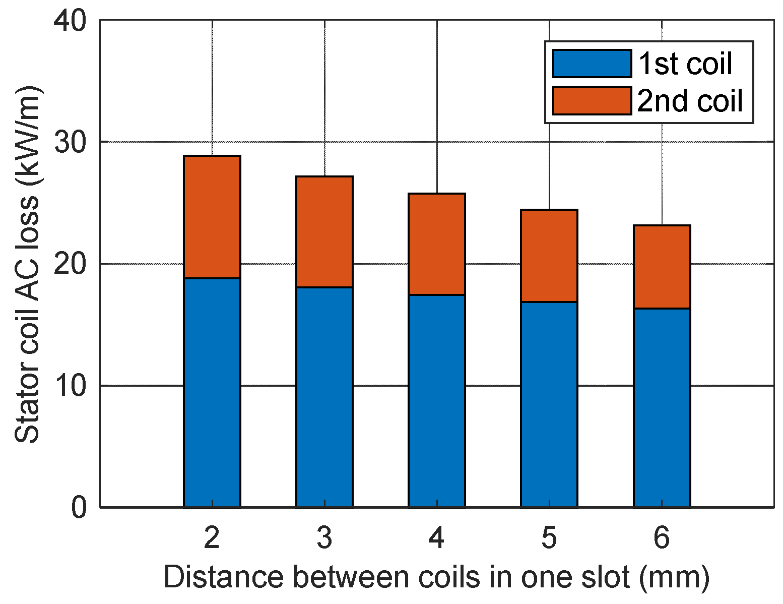
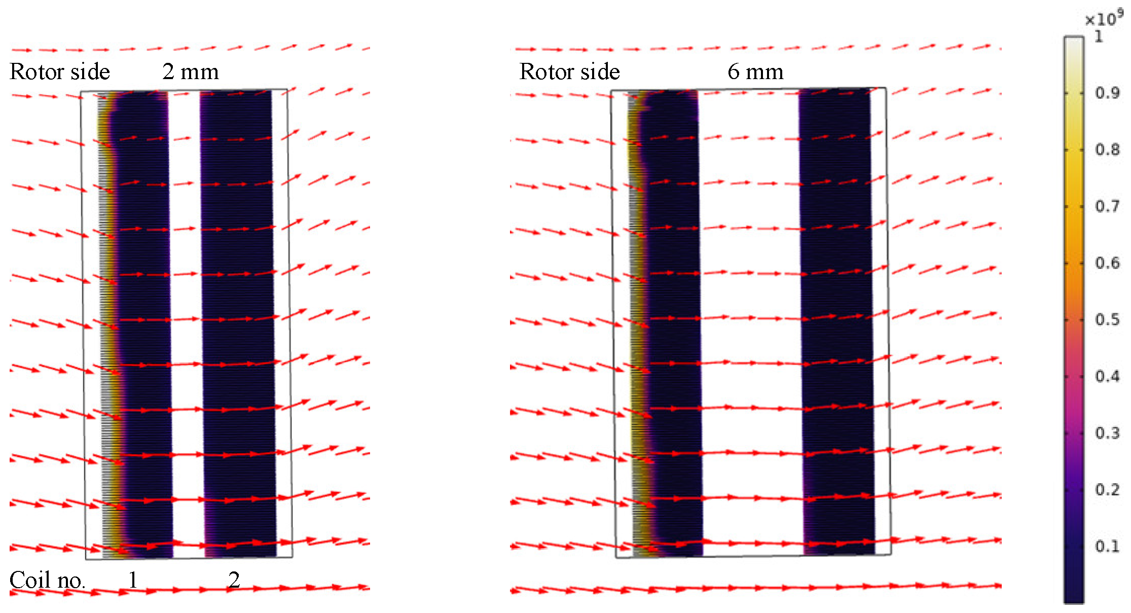
When the distance of the racetrack coils in one slot is increased, the AC loss of the stator coils is decreased as illustrated in
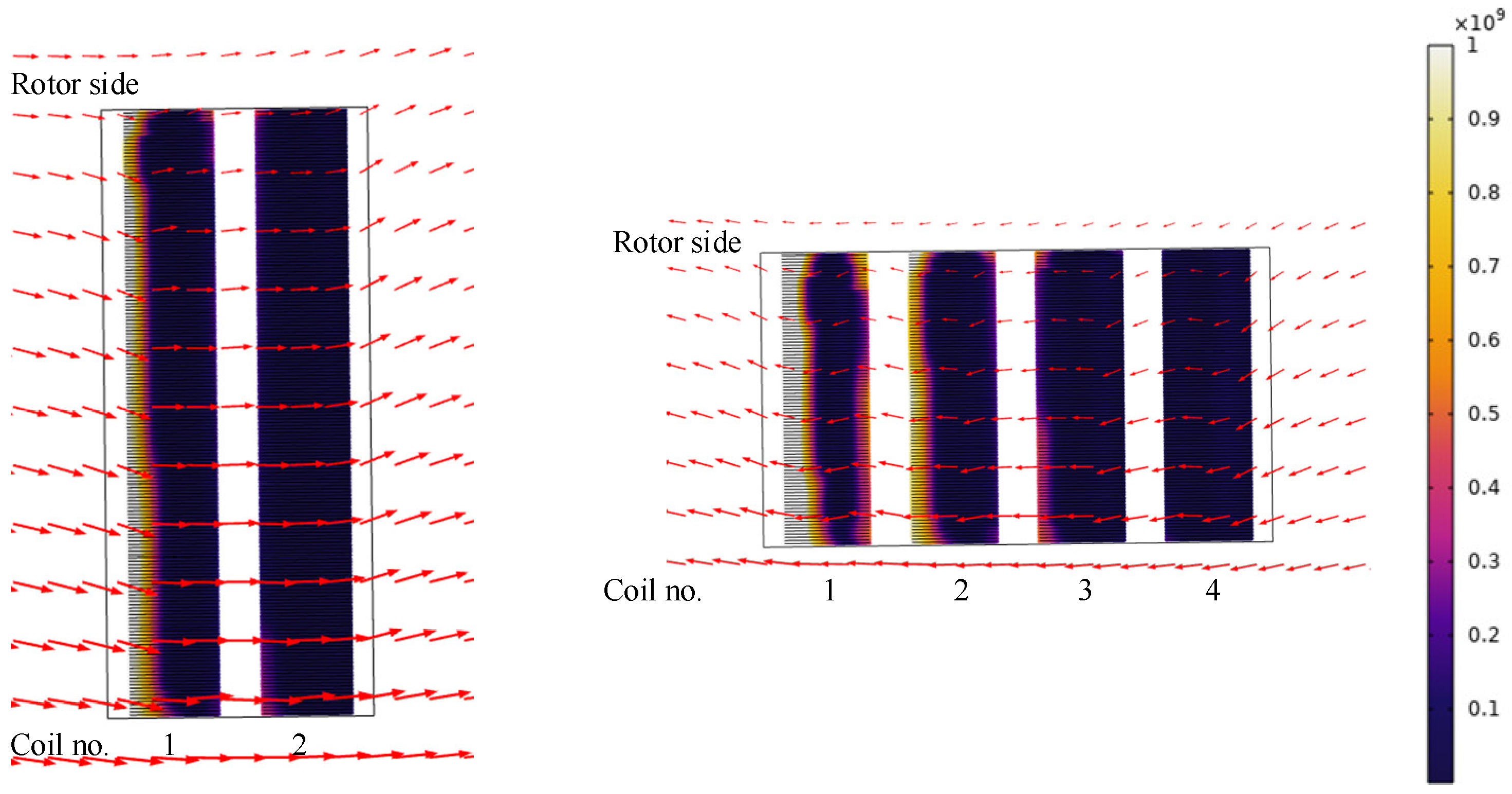
Figure 10. When the distance is larger, the self-field influence of the coils in the same slot becomes smaller. Hence, the AC loss of both layers becomes smaller. By increasing the distance to 6 mm, the AC loss of the stator coils reduces to 23.2 kW/m, which is 19.7% reduction. When the instantaneous power dissipation reaches the maximum in one period, the instantaneous power dissipation and magnetic field are shown in
Figure 11. The higher loss region is smaller by using 6 mm for the distance.
4.3. Influence of the Number of Racetrack Coils in One Slot
The total number of turns of the stator coils in one slot is 360. In the above section, there are two racetrack coils of 180 turns in the same slot as shown in
Figure 11. Two other configurations are considered in this section: three racetrack coils of 120 turns and four racetrack coils of 90 turns in one slot. This makes the cross section of coils in one slot from “fat and short” to “thin and tall” seen from the radial direction as shown in
Figure 12. The AC loss of the stator coils is listed in
Table 4. The AC loss of the stator coils is higher when the number of coils in one slot is larger, that is, the “fatter and shorter” coil has smaller AC loss. From
Figure 12 it can be seen that even more perpendicular field is in the first two coils when there are four coils in one slot. Compared to two coils in one slot, the AC loss of the stator coils is increased by 50.2%.
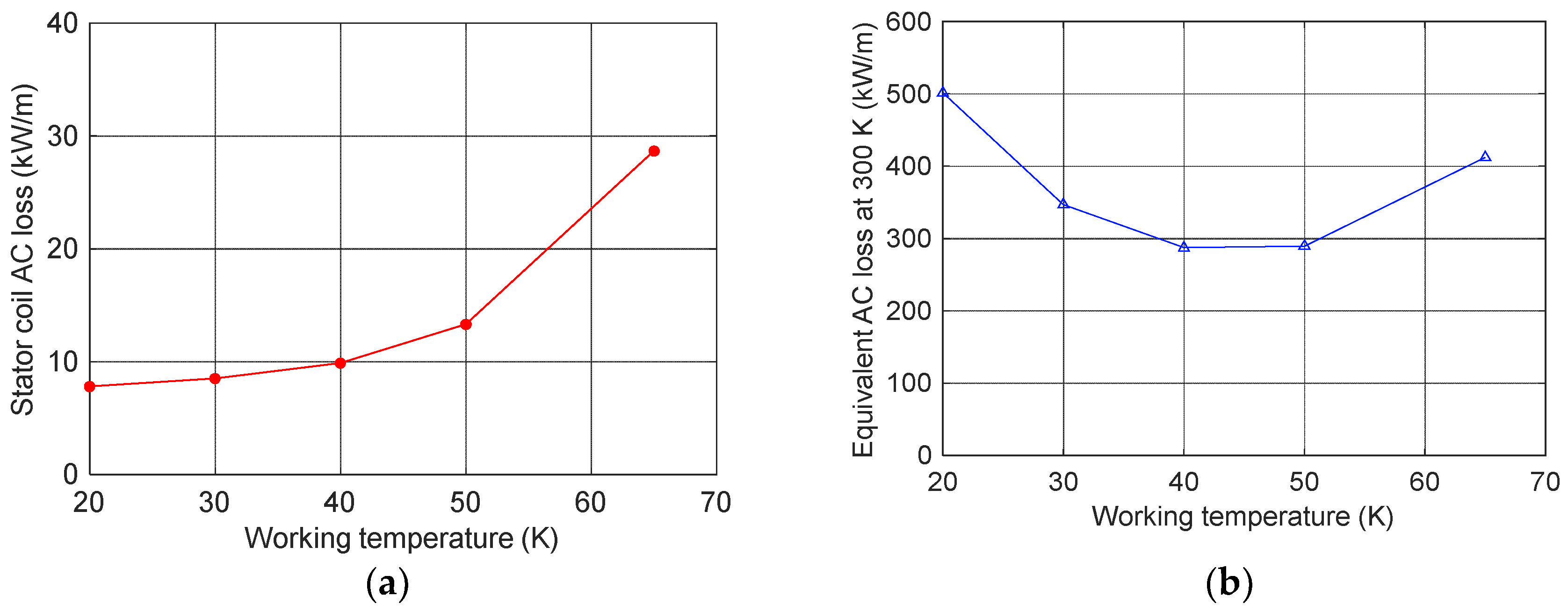
4.4. Influence of Temperature
By using the fitting parameters, presented in
Table 1, the influence of temperature on the AC loss of the stator coil has been studied. Since the critical current was increased by lowering the working temperatures, the AC loss of the stator coils was also reduced, as shown in
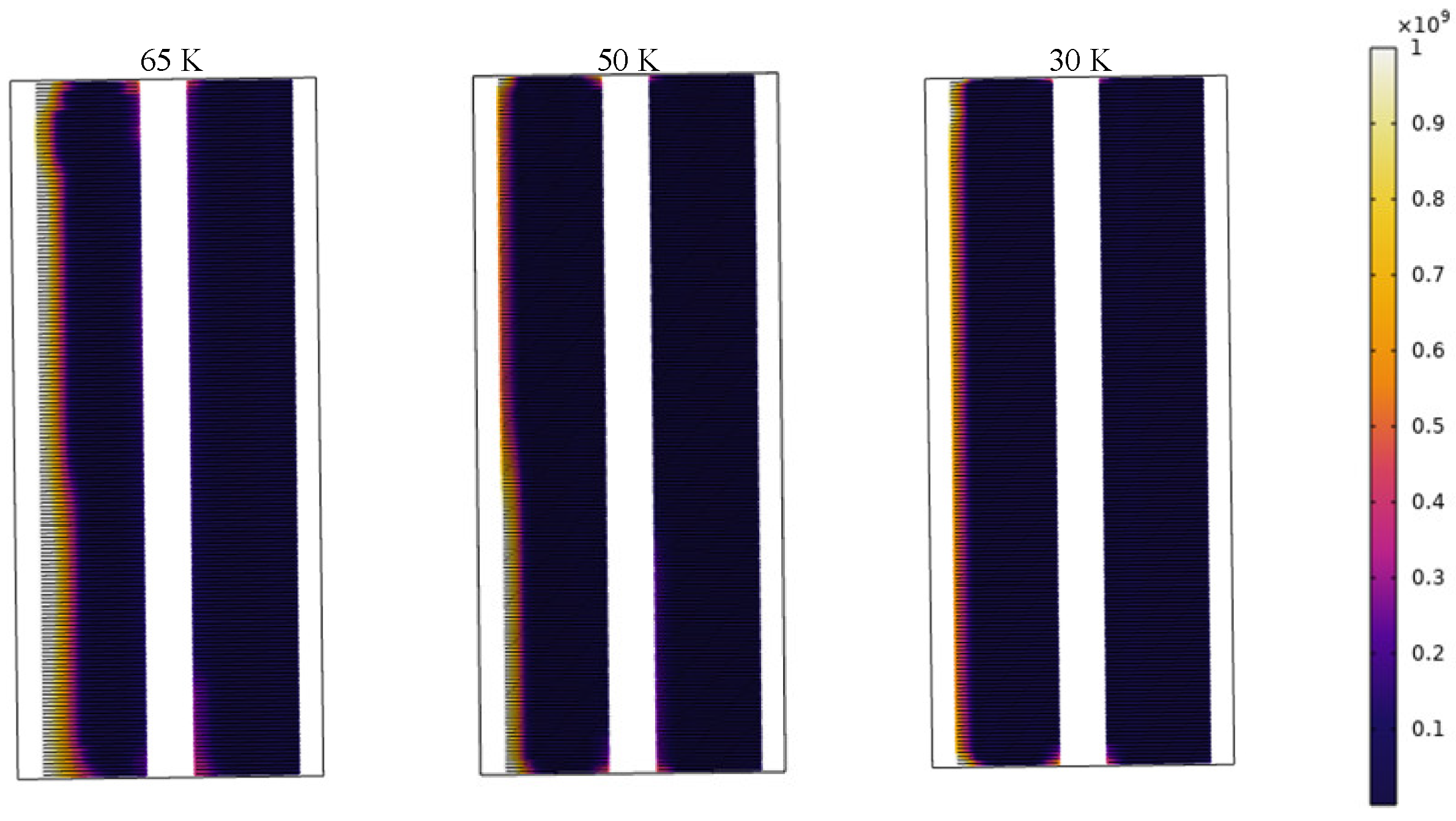
Figure 13a, and the loss region with different working temperatures is illustrated in
Figure 14. When the temperature was reduced to 50 K, the AC loss of the stator coils decreased to 13.3 kW/m, which was a 54.0% reduction, compared to that of 65 K. However, the cooling efficiency decreased with the decreasing temperature. In order to take the cooling efficiency into consideration, the AC loss of the stator coils was converted to the equivalent loss at 300 K, by employing the cooling efficiency in [
22], which is shown in
Figure 13b. The equivalent AC loss at 300 K was reduced from 411.8 kW/m to 289.5 kW/m when the working temperature was decreased from 65 K to 50 K, which was a 29.7% reduction.
5. Conclusions
In order to study the potential of a fully superconducting generator, an in-house model was developed to design a fully superconducting wind generator which has no stator iron teeth or rotor iron poles. There are two challenges in the design of this type of generator: (a) the determination of the operating currents in the stator and rotor coils, and the determination of operating relative permeability of the stator and rotor cores are dependent on each other due to their nonlinear relation to the magnetic field; and (b) the complexity of the AC loss estimation of the stator coils due to the combined effects of AC magnetic field and supplied AC current. To tackle these challenges, an iteration process based on analytical equations was developed for the determination of operating current and relative permeability and for the updates of geometry parameters. Then these were used as the input parameters for the AC loss estimation model through finite element software to evaluate the AC loss of the stator coils and to verify the generator torque.
The developed model was used to analyze 10 004DW superconducting wind generators and we found that all the designed generators have a superconductor length longer than 200 km since we use as little iron material as possible. Since the weight of the active materials, the AC loss of stator coils and the superconductor length could not be simultaneously minimized, we chose a design with lower stator AC loss, shorter superconductor length and smaller active material weight, that is, 22.8 ton of active material weight, 211.7 km of superconductor length, and 40.1 kW of stator coil AC loss including end windings at 65 K (26.1 kW without end windings). Even though the model was used to design a 10 MW wind generator, it can be applied to any other power ratings of superconducting machines for other applications.
In order to reduce the AC loss of the stator coils, several impacting factors were discussed. We found that reducing the tape from 4 mm to 2 mm cannot decrease the AC loss of stator coils due to the complex magnetic field combination from rotor coils, stator coils in other slots and self-field. This is different from the case where iron teeth and iron core can shield most of the field from rotor coils and stator coils in other slots. Another finding is that the geometry of the superconducting coils in the stator slots can influence the AC loss of stator coils as well. It can be concluded that a larger distance between the superconducting coils in the same slot and a smaller number of coils in one slot can reduce the AC loss. In addition, the influence of working temperature was investigated. By decreasing the temperature from 65 K to 50 K, the AC loss reduce by 54.0%. However, considering the cooling efficiency, the reduction of the equivalent loss at 300 K is only 29.7%. Since the complexity of magnetic field, AC current and material properties in the generator, the AC loss reduction is not an easy task. It will need careful analysis to reach the reduction target.
In the practical manufacturing and installation of the superconducting generators, there are lots of uncertainties, such as manufacturing tolerances in design dimensions, deviations of material properties, temperature changes and so on. These uncertainties may cause the decrease or even faults of the electromagnetic performance of the fully superconducting generator. It is important to combine the developed model in the paper with the robust optimization of the fully superconducting generator to avoid the risk. Hence, our next step is to integrate the developed model into robustness optimization, including optimization space and variables, optimization algorithm, surrogate model and the 6σ robustness evaluation criterion.
Author Contributions
Conceptualization, Y.L. and F.G.; writing—original draft preparation, Y.L.; writing—review and editing, F.G., J.C., L.L., C.Z., M.W., F.X., J.L., M.N. Supervision, L.L. and M.N. All authors have read and agreed to the published version of the manuscript.
Funding
This research was supported by the Fundamental Research Funds for the Central Universities, grant number FRFCU5710050221.
Institutional Review Board Statement
Not applicable.
Informed Consent Statement
Not applicable.
Acknowledgments
The authors thank C. Vargas-Llanos with Institute for Technical Physics, Karlsruhe Institute of Technology, for sharing comments regarding the AC loss reduction through smaller tape width.
Conflicts of Interest
The authors declare no conflict of interest.
References
- Song, X.; Buhrer, C.; Brutsaert, P.; Krause, J.; Ammar, A.; Wiezoreck, J.; Hansen, J.; Rebsdorf, A.V.; Dhalle, M.; Bergen, A.; et al. Designing and Basic Experimental Validation of the World’s First MW-Class Direct-Drive Superconducting Wind Turbine Generator. IEEE Trans. Energy Convers. 2019, 34, 2218–2225. [Google Scholar] [CrossRef]
- Song, X.; Buhrer, C.; Molgaard, A.; Andersen, R.S.; Brutsaert, P.; Bauer, M.; Hansen, J.; Rebsdorf, A.V.; Kellers, J.; Winkler, T.; et al. Commissioning of the World’s First Full-Scale MW-Class Superconducting Generator on a Direct Drive Wind Turbine. IEEE Trans. Energy Convers. 2020, 35, 1697–1704. [Google Scholar] [CrossRef]
- Song, X.; Buhrer, C.; Brutsaert, P.; Ammar, A.; Krause, J.; Bergen, A.; Winkler, T.; Dhalle, M.; Hansen, J.; Rebsdorf, A.V.; et al. Ground Testing of the World’s First MW-Class Direct-Drive Superconducting Wind Turbine Generator. IEEE Trans. Energy Convers. 2020, 35, 757–764. [Google Scholar] [CrossRef]
- Hoang, T.-K.; Queval, L.; Berriaud, C.; Vido, L. Design of a 20-MW Fully Superconducting Wind Turbine Generator to Minimize the Levelized Cost of Energy. IEEE Trans. Appl. Supercond. 2018, 28, 1–5. [Google Scholar] [CrossRef]
- Miura, S.; Iwakuma, M.; Izumi, T. Lightweight Design of Tens-MW Fully-Superconducting Wind Turbine Generators With High-Performance REBa2Cu3Oy Wires. IEEE Trans. Appl. Supercond. 2020, 30, 1–6. [Google Scholar] [CrossRef]
- Sumption, M.D. AC Loss of Superconducting Materials in Motors and Generators for Very High Density Motors and Generators for Hybrid-Electric Aircraft. In 2018 AIAA/IEEE Electric Aircraft Technologies Symposium; American Institute of Aeronautics and Astronautics: Cincinnati, OH, USA, 2018. [Google Scholar] [CrossRef]
- Sumption, M.D. AC Loss of Superconducting Materials- Refined Loss Estimates for Very High Density Motors and Generators for Hybrid-Electric Aircraft: MgB2 Wires, Coated Conductor Tapes and Wires. In AIAA Propulsion and Energy 2019 Forum; American Institute of Aeronautics and Astronautics: Indianapolis, IN, USA, 2019. [Google Scholar] [CrossRef]
- Terao, Y.; Kong, W.; Ohsaki, H.; Oyori, H.; Morioka, N. Electromagnetic Design of Superconducting Synchronous Motors for Electric Aircraft Propulsion. IEEE Trans. Appl. Supercond. 2018, 28, 1–5. [Google Scholar] [CrossRef]
- Ozaki, K.; Doi, Y.; Yoshida, K.; Miura, S.; Sasayama, T.; Yoshida, T.; Yamamoto, K.; Iwakuma, M.; Kawagoe, A.; Tomioka, A.; et al. Conceptual Design of Superconducting Induction Motors Using REBa2Cu 3Oy Superconducting Tapes for Electric Aircraft. IEEE Trans. Appl. Supercond. 2020, 30, 1–5. [Google Scholar] [CrossRef]
- Grilli, F.; Benkel, T.; Hänisch, J.; Lao, M.; Reis, T.; Berberich, E.; Wolfstädter, S.; Schneider, C.; Miller, P.; Palmer, C.; et al. Superconducting Motors for Aircraft Propulsion: The Advanced Superconducting Motor Experimental Demonstrator Project. J. Phys. Conf. Ser. 2020, 1590, 012051. [Google Scholar] [CrossRef]
- Benkel, T.; Lao, M.; Liu, Y.; Pardo, E.; Wolfstadter, S.; Reis, T.; Grilli, F. T–A -Formulation to Model Electrical Machines With HTS Coated Conductor Coils. IEEE Trans. Appl. Supercond. 2020, 30, 1–7. [Google Scholar] [CrossRef] [Green Version]
- Huang, X.; Huang, Z.; Xu, X.; Wang, L.; Li, W.; Jin, Z. A Fully Coupled Numerical Method for Coated Conductor HTS Coils in HTS Generators. IEEE Trans. Appl. Supercond. 2020, 30, 1–6. [Google Scholar] [CrossRef]
- Vargas-Llanos, C.R.; Lengsfeld, S.; Noe, M.; Arndt, T.; Grilli, F. Influence of Coil Position on AC Losses of Stator Superconducting Windings of a Synchronous Machine for a 10 MW Wind Turbine. IEEE Trans. Appl. Supercond. 2021, 31, 1–9. [Google Scholar] [CrossRef]
- Liu, Y.; Ou, J.; Cheng, Y.; Schreiner, F.; Zhang, Y.; Vargas-Llanos, C.; Grilli, F.; Qu, R.; Doppelbauer, M.; Noe, M. Investigation of AC Loss of Superconducting Field Coils in a Double-Stator Superconducting Flux Modulation Generator by Using T-A Formulation Based Finite Element Method. Supercond. Sci. Technol. 2021, 34, 055009. [Google Scholar] [CrossRef]
- Corduan, M.; Boll, M.; Bause, R.; Oomen, M.P.; Filipenko, M.; Noe, M. Topology Comparison of Superconducting AC Machines for Hybrid Electric Aircraft. IEEE Trans. Appl. Supercond. 2020, 30, 1–10. [Google Scholar] [CrossRef] [Green Version]
- Bong, U.; An, S.; Voccio, J.; Kim, J.; Lee, J.T.; Lee, J.; Han, K.J.; Lee, H.; Hahn, S. A Design Study on 40 MW Synchronous Motor With No-Insulation HTS Field Winding. IEEE Trans. Appl. Supercond. 2019, 29, 1–6. [Google Scholar] [CrossRef]
- Liu, Y. Design of a Superconducting DC Wind Generator. Ph.D. Thesis, Karlsruhe Institut für Technologie (KIT), Karlsruhe, Germany, 2018. [Google Scholar]
- Zou, S.; Zermeno, V.M.R.; Grilli, F. Simulation of Stacks of High-Temperature Superconducting Coated Conductors Magnetized by Pulsed Field Magnetization Using Controlled Magnetic Density Distribution Coils. IEEE Trans. Appl. Supercond. 2016, 26, 1–5. [Google Scholar] [CrossRef] [Green Version]
- Liu, Q.; Hameyer, K. Torque Ripple Minimization for Direct Torque Control of PMSM With Modified FCSMPC. IEEE Trans. Ind. Applicat. 2016, 52, 4855–4864. [Google Scholar] [CrossRef]
- Mikitik, G.P.; Mawatari, Y.; Wan, A.T.S.; Sirois, F. Analytical Methods and Formulas for Modeling High Temperature Superconductors. IEEE Trans. Appl. Supercond. 2013, 23, 8001920. [Google Scholar] [CrossRef]
- Schönborg, N. Hysteresis Losses in a Thin High-Temperature Superconductor Strip Exposed to Ac Transport Currents and Magnetic Fields. J. Appl. Phys. 2001, 90, 5. [Google Scholar] [CrossRef]
- Radenbaugh, R. Refrigeration for Superconductors. Proc. IEEE 2004, 92, 1719–1734. [Google Scholar] [CrossRef]
Figure 1.
The structure of the generator.
Figure 1.
The structure of the generator.
Figure 2.
The general procedure of the design model.
Figure 2.
The general procedure of the design model.
Figure 3.
Illustration of the generator’s geometry.
Figure 3.
Illustration of the generator’s geometry.
Figure 4.
B–H curve of M235-35A from Stiefelmayer-Lasertechnik GmbH at 50 Hz.
Figure 4.
B–H curve of M235-35A from Stiefelmayer-Lasertechnik GmbH at 50 Hz.
Figure 5.
Proposed iteration process of operating-point determination.
Figure 5.
Proposed iteration process of operating-point determination.
Figure 6.
User interface of the design model of fully superconducting generators.
Figure 6.
User interface of the design model of fully superconducting generators.
Figure 7.
The active material weight, superconductor length, and AC loss of the stator coils as a function of air-gap diameter and pole pair number: (a) active material weight, (b) superconductor length, (c) stator coil AC loss without end windings, and (d) stator coil AC loss including end windings.
Figure 8.
Design results of the 10 MW fully superconducting wind generators: (a) scatter points of AC loss of stator coils and superconductor length, (b) scatter points of active material weight and superconductor length.
Figure 8.
Design results of the 10 MW fully superconducting wind generators: (a) scatter points of AC loss of stator coils and superconductor length, (b) scatter points of active material weight and superconductor length.
Figure 9.
The instantaneous power dissipation (W/m3) reach the maximum in one period and magnetic field (red arrows) with tape width of 4 mm, 2 mm, and 1 mm, from left to right.
Figure 9.
The instantaneous power dissipation (W/m3) reach the maximum in one period and magnetic field (red arrows) with tape width of 4 mm, 2 mm, and 1 mm, from left to right.
Figure 10.
AC loss of stator coils as a function of distance between coils in one slot.
Figure 10.
AC loss of stator coils as a function of distance between coils in one slot.
Figure 11.
The instantaneous power dissipation (W/m3) reach the maximum in one period and magnetic field (red arrows).
Figure 11.
The instantaneous power dissipation (W/m3) reach the maximum in one period and magnetic field (red arrows).
Figure 12.
The instantaneous power dissipation (W/m3) reach the maximum in one period and magnetic field (red arrows) with 2 coils and 4 coils in one slot from left to right.
Figure 12.
The instantaneous power dissipation (W/m3) reach the maximum in one period and magnetic field (red arrows) with 2 coils and 4 coils in one slot from left to right.
Figure 13.
The AC loss of the stator coils and the equivalent loss at 300 K as a function of temperature: (a) The AC loss of the stator coils at cryogenic temperature, (b) The equivalent AC loss of stator coils at 300 K.
Figure 13.
The AC loss of the stator coils and the equivalent loss at 300 K as a function of temperature: (a) The AC loss of the stator coils at cryogenic temperature, (b) The equivalent AC loss of stator coils at 300 K.
Figure 14.
The instantaneous power dissipation (W/m3) reach the maximum in one period at different working temperature.
Figure 14.
The instantaneous power dissipation (W/m3) reach the maximum in one period at different working temperature.
Table 1.
Fitted parameters for the lift factor in Equation (7).
Table 1.
Fitted parameters for the lift factor in Equation (7).
| T (K) | L0 (T) | k (T) | Bc0 (T) | b (T) |
|---|
| 20 | 6.52 | 0.06 | 5.04 | 1.64 |
| 30 | 6.12 | 0.07 | 3.23 | 1.41 |
| 40 | 5.29 | 0.10 | 1.86 | 1.12 |
| 50 | 4.12 | 0.17 | 1.26 | 0.96 |
| 65 | 2.44 | 0.61 | 0.59 | 0.77 |
Table 2.
Key parameters of the selected design.
Table 2.
Key parameters of the selected design.
| Parameters | Values | Units |
|---|
| Power | 10 | MW |
| Frequency | 4 | Hz |
| Stator coil inner diameter | 5000 | mm |
| Stator coil outer diameter | 5024 | mm |
| Number of turns per slot | 360 | -- |
| Number of racetrack coils per slot | 2 | -- |
| Number of slots per pole | 6 | -- |
| Current of stator coil (65 K) | 70 | A |
| Stator core inner diameter | 5074 | mm |
| Stator core outer diameter | 5262 | mm |
| Rotor coil inner diameter | 4856 | mm |
| Rotor coil outer diameter | 4880 | mm |
| Number of turns per pole | 528 | -- |
| Number of racetrack coils per pole | 2 | -- |
| Current of rotor coil (30 K) | 261 | A |
| Rotor core inner diameter | 4594 | mm |
| Rotor core outer diameter | 4806 | mm |
| Number of poles | 48 | -- |
| Axial stack length | 902 | mm |
| Active material weight | 22.8 | ton |
| Superconductor length | 211.7 | km |
| Stator coil AC loss (65 K) | 40.1 | kW |
Table 3.
AC loss of stator coils with different widths.
Table 3.
AC loss of stator coils with different widths.
| Coil No. | 4 mm | 2 mm | 1 mm |
|---|
| 1 | 18.80 kW/m | 13.15 kW/m | 4.31 kW/m |
| 2 | 10.07 kW/m | 7.66 kW/m | 3.51 kW/m |
| 3 | -- | 3.71 kW/m | 2.81 kW/m |
| 4 | -- | 4.85 kW/m | 2.18 kW/m |
| 5 | -- | -- | 1.61 kW/m |
| 6 | -- | -- | 1.07 kW/m |
| 7 | -- | -- | 0.86 kW/m |
| 8 | -- | -- | 1.12 kW/m |
| Total | 28.9 kW/m | 29.4 kW/m | 17.5 kW/m |
Table 4.
AC loss of stator coils with different number of coils in one slot.
Table 4.
AC loss of stator coils with different number of coils in one slot.
| Coil No. | 2 Coils | 3 Coils | 4 Coils |
|---|
| 1st | 18.80 kW/m | 20.49 kW/m | 19.71 kW/m |
| 2nd | 10.07 kW/m | 7.64 kW/m | 9.89 kW/m |
| 3rd | -- | 9.16 kW/m | 5.81 kW/m |
| 4th | -- | -- | 7.95 kW/m |
| Total | 28.9 kW/m | 37.3 kW/m | 43.4 kW/m |
| Publisher’s Note: MDPI stays neutral with regard to jurisdictional claims in published maps and institutional affiliations. |
© 2021 by the authors. Licensee MDPI, Basel, Switzerland. This article is an open access article distributed under the terms and conditions of the Creative Commons Attribution (CC BY) license (https://creativecommons.org/licenses/by/4.0/).


 ,
, 


