Article

Ground Fracture Development and Surface Fracture Evolution in N00 Method Shallowly Buried Thick Coal Seam Mining in an Arid Windy and Sandy Area: A Case Study of the Ningtiaota Mine (China)

1
Institute of Land Reclamation and Ecological Restoration, China University of Mining and Technology, Beijing 100083, China
2
Shannxi Coal and Chemical Industry Group, Xi’an 710054, China
3
School of Environment Science and Spatial Informatics, China University of Mining and Technology, Xuzhou 221116, China
4
College of Civil Engineering, Henan University of Engineering, Zhengzhou 451191, China
*
Author to whom correspondence should be addressed.
Energies 2021, 14(22), 7712; https://doi.org/10.3390/en14227712
Submission received: 7 October 2021 / Revised: 14 November 2021 / Accepted: 16 November 2021 / Published: 17 November 2021

Abstract

:
An observatory was established at the Ningtiaota Mine (China) in order to investigate the surface deformation pattern of N00 method workings mining in shallow buried thick coal seams in a windy-sand area. The observatory allows one to measure the coupling between the periodic changes of parameters related to ground subsidence and ground cracks with workings advancement. The data monitored in the field indicate that when the adjacent mining workings are mined below the ground, a sinkhole basin with a larger impact area will be formed. New ground fractures are formed above the mining area to connect with the fractures above the mining face. As a consequence a new pattern of “O” circle distribution beyond the working face is formed, which develops rapidly during the working face recovery. In addition, the dynamic fractures in coal mining are characterized by the phenomenon of self-healing. Our findings will help to protect the surface environment of the mine area during shallow buried high-intensity mining activities in the Lime Tower coal mine, and are also an important guideline in other windy beach mining areas.

Graphical Abstract

1. Introduction

The study of the impact of mining activity on the ground surface started in 1825, when Lehmann proposed the theory of “sinking basin” to delineate the tensile and compressive deformation zones within the working face [1]. The theory was subsequently widely used in the study of surface subsidence and deformation caused by coal mining [2]. It is found that the depth, profile morphology, and influence range of sinkhole basin depend on the geological conditions of coal seam deposit, mining method, surface environment, rock mechanics, etc. Two types of coal mining collapse exist, continuous subsidence and discontinuous subsidence [3,4,5,6,7,8,9,10,11,12]. Numerous observations and studies have been conducted on the surface deformation caused by underground mining of coal by the conventional stay-pillar longwall mining method. The study shows that the surface subsidence evolves continuously and synergistically in time and space.
As one of the main features of surface deformation, ground cracks not only have a great impact on the original landscape structure, but also threaten the natural ecological environment of the surface [13]. Therefore, it is very meaningful to study the mechanism of coal mining subsidence surface cracks generation in detail. The major cause of mining-induced ground fractures is the bottom–up transfer of stress through rock layers to the surface [12,14,15,16,17,18,19], which is influenced by the nature of the bedrock and other factors, such as thickness of the coal sea. The mining method and mining direction also affect the characteristics (e.g., width, depth, and shape) and distribution of fractures in coal mining collapses [20]. Bouwer H. [21] studied surface subsidence and ground fractures caused by over-extraction of groundwater. Akagi T. [22], Phien-Wej N. [23], and Sideri D. [24] studied the surface deformation and ground fractures caused by groundwater overpumping in Japan, Thailand, and Greece, respectively. Ghazifard A. et al. [25] studied the characteristics of ground fracture distribution caused by groundwater extraction in Damaneh city, Iran. Sepe V. et al. [26] studied the problem of surface non-uniform subsidence caused by fracture closure of geotechnical layers due to geothermal resource extraction in Ischia Island, Italy. Ide T.S. et al. [27], on the other hand, studied the surface fractures caused by subsurface rock structure sinking and destabilization due to spontaneous combustion in underground coal fields. Trivino L.F. et al. [28] studied the characteristics of rock fracture opening and closing caused in coal bed methane mining. Abdallah M. et al. [29] studied the effect of mining ground fractures on surface masonry walls. Graff J.V.D. et al. [30] investigated the formation mechanism of post-mining tensile mining ground fractures and rock fracture closure in a mine in the Wasatch Plateau coalfield, Utah, USA. Thompson J.A. et al. [31] observed in the field the distribution of mining ground fractures and their impact on nearby vineyards in the Hunter Valley, Australia. In the 1990s, Chinese scholars began to study ground fractures. In recent years, Zhou [32], Deng [33], Xu [34,35], and Li [36] have combined ground fracture, surface movement, and rock movement to study their formation mechanism. A certain amount of field work has been conducted to explore the mechanism by which ground fractures may lead to the redevelopment of fractures that were caused by previous mining on the fracture zone related to mining below the earlier mined areas [19,37,38,39,40,41,42,43]. At the beginning of the 21st century, the theory of “short-armed beam with cut roof” was proposed and successfully applied in the Lizhita coal mine in the northern Shaanxi province [44]. The successful application of this theory marked China’s entry into the era of cut roof pressure relief automatic lane formation without the use of coal pillars [45,46]. This progress designated China’s entry into the era of automatic coal pillarless mining technology.
Although several studies had focused on surface subsidence and surface fractures caused by mining [37,38], research on the formation mechanism of surface subsidence and surface fractures caused by N00 method mining of shallow buried thick coal seams was lacking. Therefore, we conducted field work and corresponding theoretical analysis to explore the relationship between rock movement and ground fracture development. We will explore the synergistic evolution mechanism of surface subsidence and ground fractures under the coal pillarless mining conditions in the northern Shaanxi wind and sand area, and also predict the distribution pattern of surface fractures generated by the N00 method of shallow buried thick coal seam mining.

2. Materials and Methods

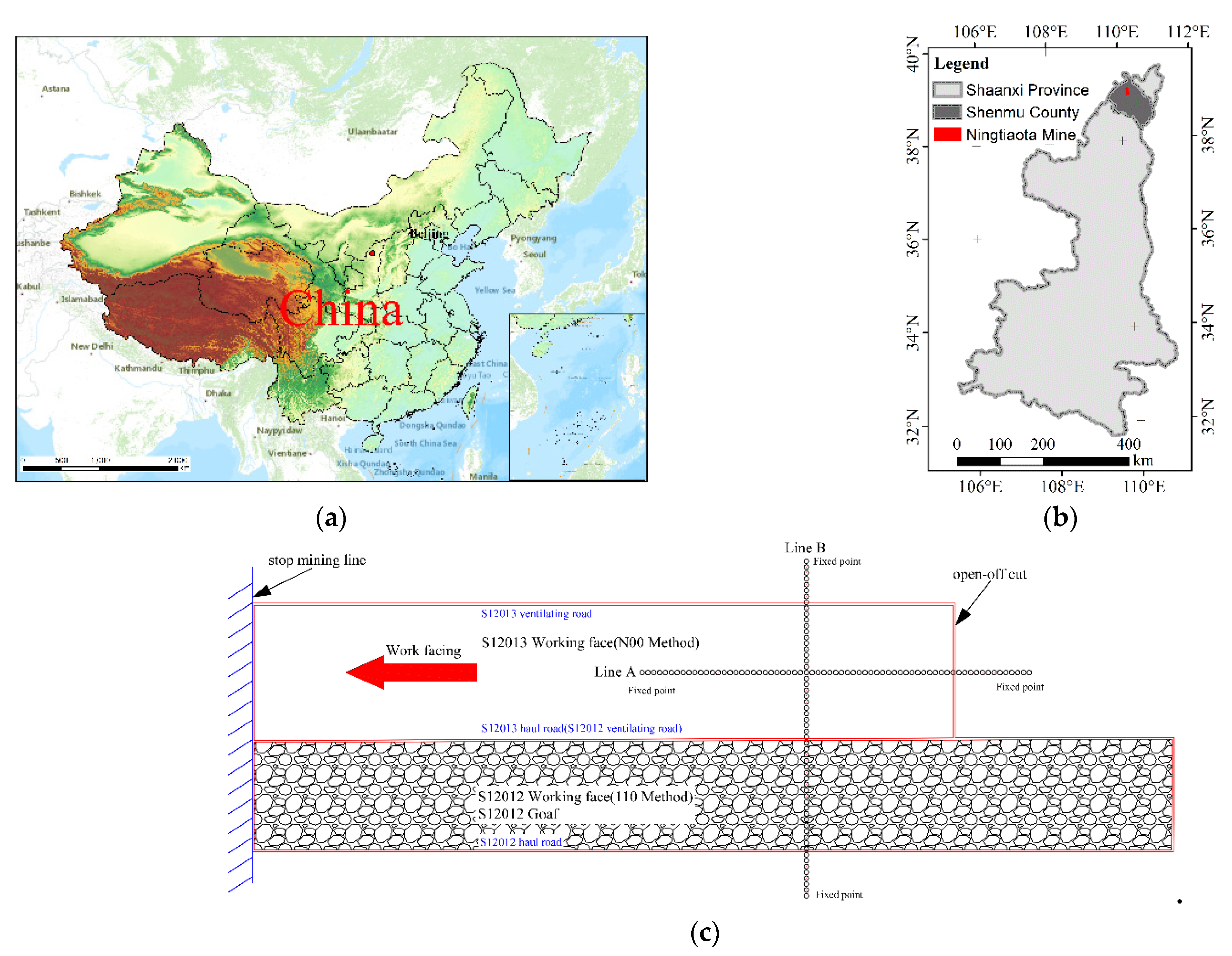
2.1. The Ningtiaota Mine

The Ningtiaota Mine is located in the North Shaanxi Mining District, at the northeast edge of the Mawusu Desert. It is one of the largest coal mines in the world and operated by the North Shaanxi Mining Corporation. The study area is a windy beach landscape with a single type of surface vegetation, scarce runoff, and extremely fragile ecological environment. The Jurassic coalfield in northern Shaanxi is geologically characterized by shallow burial, thin bedrock, thick coal seams, and thick loose layers. The Lime Tower Coal Mine is the first coal mine in the world to adopt the “110/N00” method, with S12012 working face being the first test face of the 110 method and S12013 working face being the first test face of the N00 method.
However, due to the intense mining activity in modern mines and the special geological conditions, coal mining in ecologically fragile areas has causes vast surface deformation, generating numerous surface fissures, withering vegetation, and serious damage of the infrastructure, thus endangering the local habitat.
S12013 working face is mining 2–2 coal seam. The coal seam is shallow and the average depth of burial is ca. 150 m. The coal thickness is 3.8–4.21 m and the mining height is 4 m. The coal seam is near horizontal with a dip angle of 1–2°. The thickness of overlying bedrock is 88–115 m and the average thickness of direct top is 5 m. It is mainly siltstone with horizontal laminae. In the middle a thin layer of fine sandstone occurs. The average thickness of the pseudo top is 4.8 m at the working face. The return wind chute is “110” method reserved roadway. A protection coal column between the adjacent S12012 working face is lacking, and the two working faces will be completely connected. The thickness of the overlying loose layer near the surface is 8–27 m. Due to the excessive sinking of the surface caused by the shallow buried intensive coal mining, the surface is covered with a thicker loose layer, resulting in non-linear deformation and ground cracks as the main form of surface damage. The working face length is 334 m with a strike length of 1781.9 m. The average daily mining speed is about 12 m/d. The petrophysical parameters are detailed in Table 1.

2.2. Deformation Monitoring

2.2.1. Surface Movement Deformation Monitoring Method

The observation station is situated on the ground of the working face S12013 and S12012. It consists of two observation lines, an observation line along the working face strike (named line A) and an observation line along the inclination in the ultra-sufficient mining area within the working face (named line B), perpendicular to the working face strike. The inclination line is set on the surface corresponding to the centerline of the working face (Figure 1c). The damage to the mine site from coal mining subsidence is shown in Figure 2.
Generally, the surface mobile observatory needs to cover the observed coal mining collapse beyond the impact area, including a certain range of unaffected areas. Layout regulations are detailed in Table 2.
  • The observation line should be laid on the main section of the surface moving basin.
  • The observation station area, during the observation period, is not affected by the neighboring working face mining.
  • The length of the observation line must outreach the range of the surface moving basin.
  • The density of measurement points on the observation line should be determined according to the geological mining conditions and observation purposes.
  • The control point should be set near the end of the observation line, which cannot be affected by settlement and needs to be stable and reliable for a long time.
  • The measurement points should be firmly buried, and the observation points lay within the surface movement basin should move synchronously with the surface.

2.2.2. Ground Cracks Monitoring Method

Underground coal mining disrupts the original stress balance of rock strata. This leads to surface subsidence, forming a large number of surface cracks and subsidence steps, damaging the surface soil structure, endangering the ecological environment, and even damaging the surface buildings [47,48,49]. All processes indirectly affect human activities. Especially subsequent to mining with the N00 method, it is important to study the mechanism of the formation and development of surface cracks after coal mining collapse, and to propose corresponding suitable protection activities. In this study, we will obtain the dynamic distribution development characteristics of surface fractures in coal mining working face. Multiple monitoring was conducted using RTK (real-time kinematic) and ruler, measuring the orientation of the cracks in the coal mining face and recording the width and length of the coal mining collapse cracks. In addition, the temporal and spatial variation characteristics of typical fractures are recorded. Daily recovery progress and relevant data that can reflect the movement of overlying rock layers has been recorded to explore the coupling relationship between fracture development and mining activities.

2.3. Measurement Work

Two pre-mining surface observations were completed after the observation stations were established prior to the formation of the workings. Due to intensive mining activity in the western mining area, the average daily recovery rate is larger than 10 m/d. Therefore, during the recovery period of the S12013 workings, weekly observations were made and second level observations were used to record the settlement process on the ground surface over a long period of time. The accuracy of the second-class level is within 2 mm. Three–five days of fracture distribution monitoring was carried out using RTK. It mainly consists of measuring and recording the height change of the observation point, width change and location of the ground cracks, as well as contours and distribution of the ground cracks. Dynamic fracture monitoring was carried out daily at the gently sloping ground surface in the ultra-sufficient mining area of the working face, recording the location and width changes of the fracture generation. In addition, measurements were continued until the ground deformation was stabilized.

3. Results of Monitoring and Analysis

3.1. Characteristics of Surface Collapse Basin after N00 Method Shallow Buried Single Coal Seam Mining

3.1.1. Variation Characteristics of Observation Line A at the Working Face

The final subsidence of line A (see Figure 1c) is shown in Figure 3, which reflects the trend characteristics of the center of the working face towards the subsidence basin. Figure 3 illustrates that 2.649.5 mm is the greatest surface subsidence value at the location of point B, where the shaft is mined to 1035 m and is in the super-sufficient mining area of the working face. After full mining, the maximum sinkage value is usually between 2.1 and 2.6 m. The sinkage at the boundary of the working face is steeper, showing a “concave” basin rapidly, which is in line with the sinkage law of shallow buried coal seam mining.
As shown in Figure 4, the tilt value of the observation line point B, which characterizes the degree of damage to the surface coal mining collapsed ground. At point B43, the maximum tilt value is 20.2 mm/m (435 m from the open cut) and the minimum tilt value is 58.8 mm/m (absolute value) at B17 (45 m from the open cut), indicating low tilt value near the open cut and larger values inside the working face. The data reflect that the ground settlement is caused by the sinking basin formed from the underground stratigraphic rupture to the surface.
Figure 5 shows the curvature of the observed points in line B. Excluding the anomalies, the maximum curvature should be situated between the boundary point and the inflection point with a value of 141.1 mm/m2. The maximum negative curvature occurs at the point of maximum subsidence with a value of 10.5 mm/m2 (absolute value). Figure 6 illustrates the unevenness of the ground. The presence of negative values in the unmined area documents that the terrain is not flat, and the curvature in the ultra-sufficiently mined area appears as an oscillating and fluctuating type, indicating that the surface deformation in this area is influenced by the topography.

3.1.2. Variation Characteristics of Observation Line B at the Working Face

The coal mining subsidence map of observation line B is shown in Figure 6 (see Figure 1c for location). The maximum sinkage value of the inclined line is 2407.8 mm, located in the super sufficient mining area of the working face, 375 m distant from the open cutting hole. The maximum sinkage point is offset to the adjacent S12012 working face. Since the 110/N00 method does not exist to protect the coal pillar, the pressure is released by cutting the top to achieve automatic formation and coal pillar-free mining. The rock fragmentation and expansion characteristics are used to form a larger sinkhole basin. In addition, the ground subsidence affects an area larger than the size of the underground coal mining working face (transport chute and return wind chute), It indicates that the underground mining activities lead to surface subsidence and the horizontal movement and tensile deformation of the ground surface after the breakage of the rock layer.

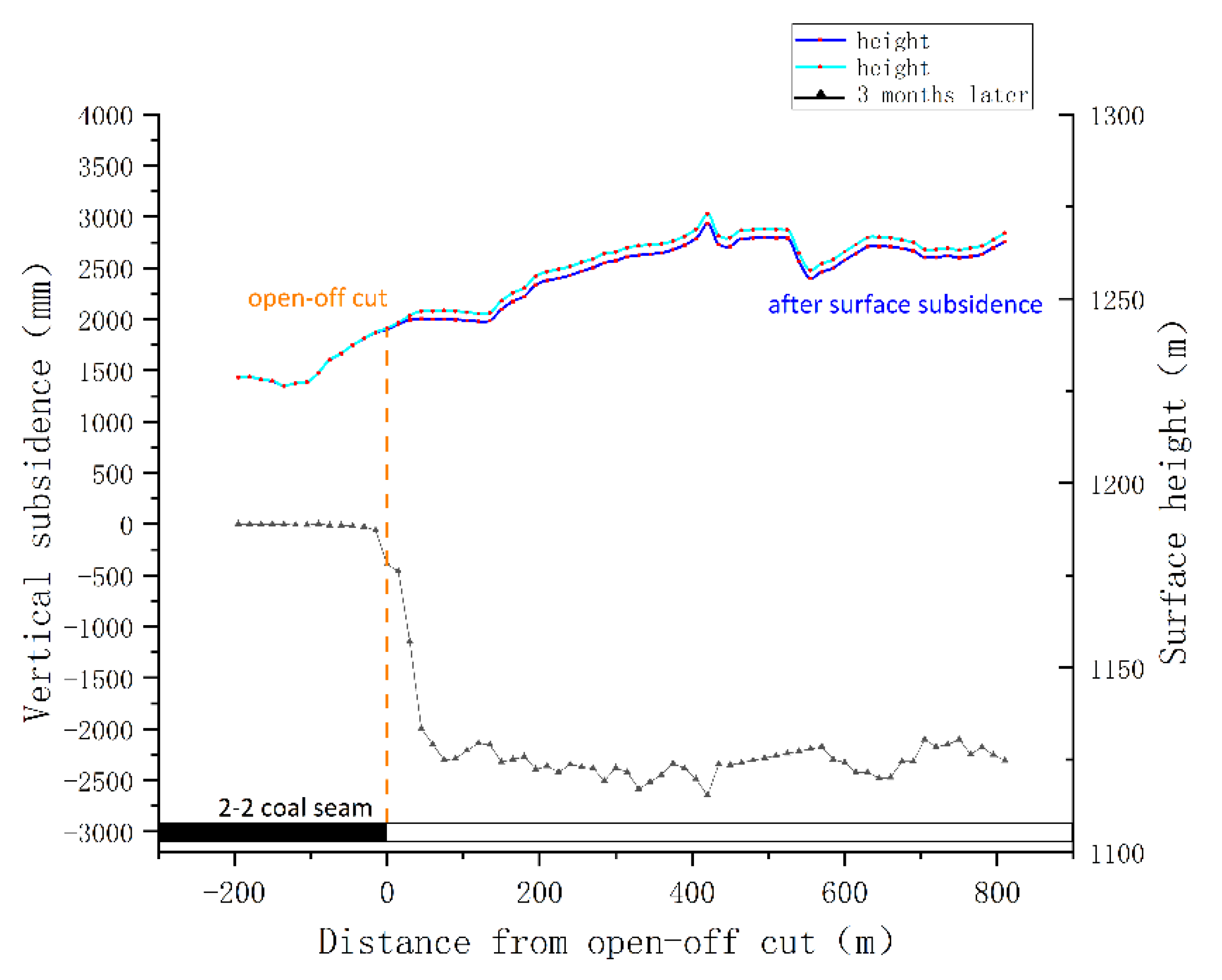
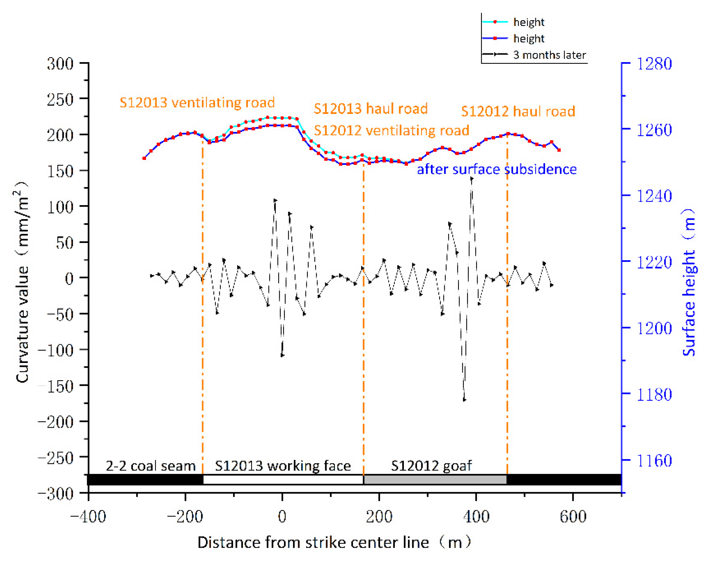
3.2. Change in Surface Subsidence Induced by the Unloading Side of the Cut Top

The final collapse basin of the surface in the inclined direction of the coal mining workings face is shown in Figure 6. The N00 method is to cut the top and unload the pressure at the down-slot position, using the rock fragmentation and expansion characteristics to make the rock strata collapse more complete. Therefore, the sinking range of the cut top pressure relief side is larger than the traditional way of leaving coal pillars. The maximum sinking value of the cut top pressure relief side is 1523.9 mm, which also reflects that the N00 method, using the rock fragmentation and expansion characteristics, can effectively lower the amount of surface subsidence, and thus achieve the protection of the ground land ecological environment.
Figure 7 shows the inclination value curve of the coal mining collapsed working face. The maximum sinkhole tilt value is 0, close to the coal-free pillar side. It is evident from the two tilt extremes that coal free-pillar mining will form larger sinkhole basins, and the sinkhole basin boundary extends toward the coal-free pillar side.
The final curvature curve on the inclined side shows that the two working faces mined without coal pillars will form a new sinkhole basin (Figure 8). The complex surface topography causes positive and negative curvature oscillations in the center of the sinkhole basin, with two maxima at the edge of the sinkhole basin.
Table 3 summarizes the parameters related to the tendency of surface deformation caused by mining of shallowly buried coal seams in similar areas. The range of surface subsidence is expanded after the N00 method of roof cutting. In addition, using 10-mm sinking as the boundary, the range of surface deformation formed by coal pillarless mining is wider than the subsidence impact of conventional left coal pillars. No coal pillar mining between adjacent working faces will form a larger sinkhole basin, and the sinking between two adjacent working faces will continue and reach the maximum sinkhole value. However, the sinkage at the N00 method cut top relief is far from the maximum sinkage value. The discrepancy is probably related to the fact that the overlying rock layer underwent active crumbling, deformation-crushing, and compaction due to the top-cut pressure relief. This led to the reduction of the displacement of the overlying rock layer and slowed down the surface subsidence.

3.3. Analysis of Surface Deformation Parameters of Coal Mining Subsidence

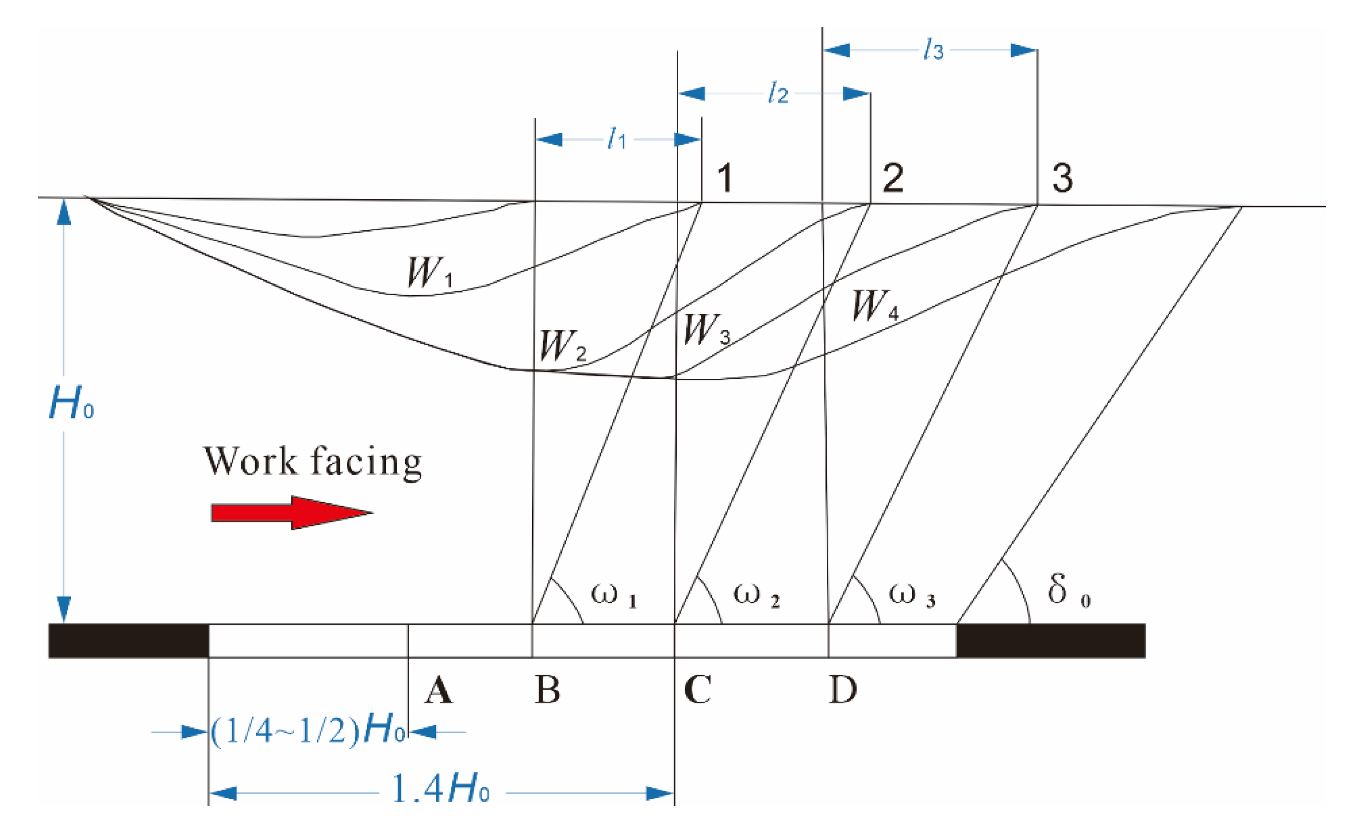
3.3.1. Analysis of the Impact of Coal Mining Subsidence Overrun

In mining subsidence science, the rock layers are constantly shifting due to the influence of underground mining activities. When the ground is fully mined, the surface in front of the workings will be continuously affected by the overrun as the workings continue to advance. Under the condition of full excavation, the angle between the line of 10-mm settlement point of the ground surface in front of the coal mining workings and the position of the coal mining workings is the overrun influence angle.
The coal mining face is excavated to A, then the surface forms a sunken basin curve W1. (Figure 9), ω is the advance influence angle. The advance influence angle is one of the important parameters of high-intensity mining and is mainly used to indicate the degree of influence associated with mining activities. It is calculated from the equation:
ω = arctan H 0 L
H0 is the mining depth, m. L is the advance impact distance, m. Based on the multi-period data monitored during the period of over-sufficient mining, a system of equations is used to calculate the advance impact angle, which is 55°. The advance impact distance is 86 m.

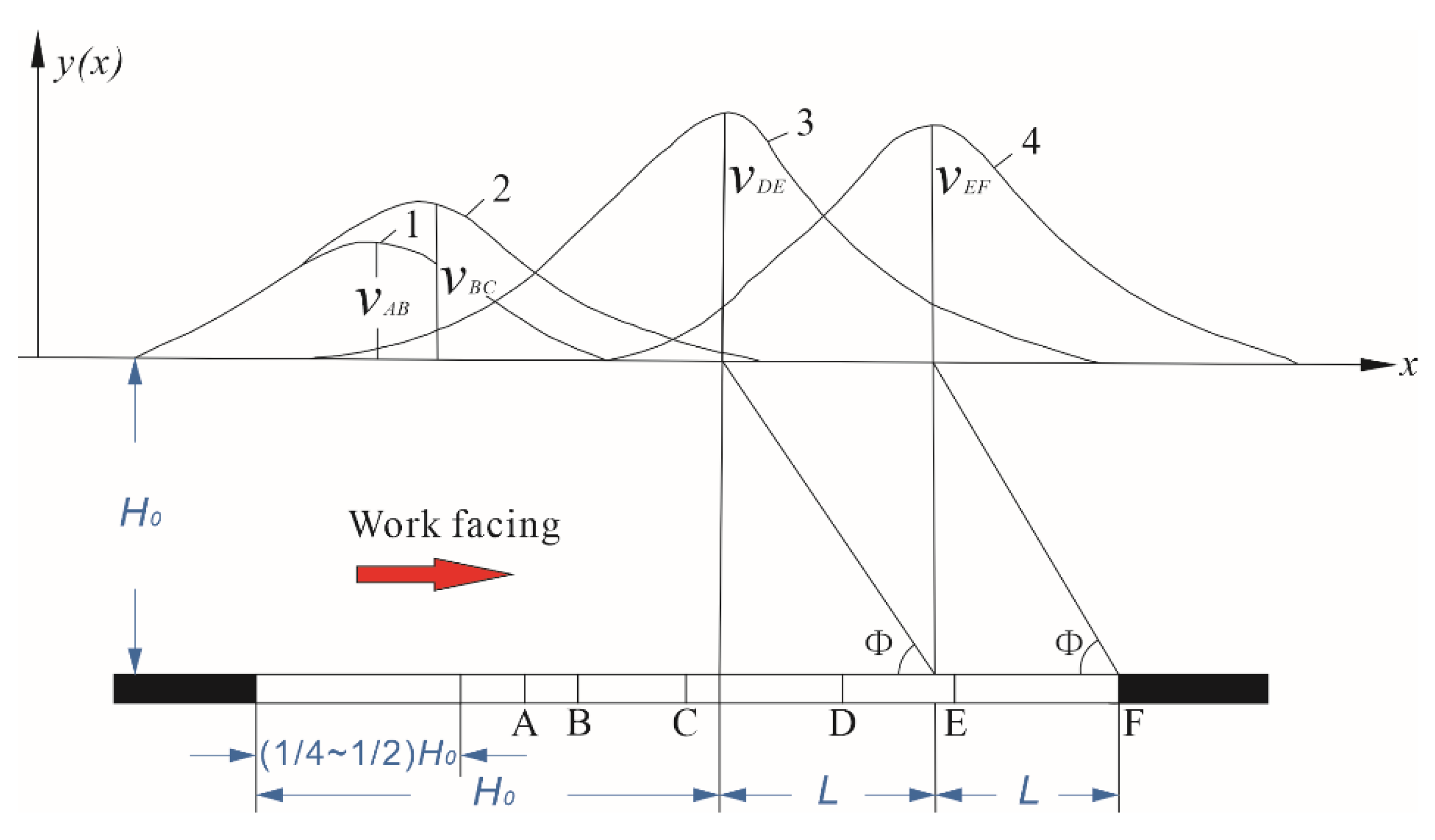
3.3.2. Parameters Related to Maximum Subsidence Velocity

The point of maximum sinking of the surface is the point of the most violent movement of the surface. The angle between the line of its position with the working face and the horizontal line of the mining area is the maximum sinking speed lag angle. Calculating its change can determine the most violent surface movement of the area. It is influenced by lithology, mining depth, and recovery speed and is calculated from the equation:
φ = a r c c o t L H 0
The mining depth is H0 and the lagging distance of maximum subsidence velocity is L. (Figure 9). The calculated maximum sinking velocity lag angle is 64.7°, and the maximum sinking lag distance is 78.8 m. The sinking velocity has the following characteristics when the ground is expressed to full mining (Figure 9): The shape of the surface sinking velocity curve is basically unchanged and the maximum point of sinking velocity moves forward regularly.

3.3.3. Subsidence Coefficient and Basis Mining Ratio

The subsidence factor is the ratio of the maximum surface subsidence value Wcm to the projected length of the coal seam normal to the mining thickness M in the plumb direction when completely mined. The mining thickness and depth of burial are the most important influencing factors on the ground movement deformation. Usually, the following equation is used to calculate the subsidence factor after excavation of the coal seam:
W c m = q M c o s α
W c m is the maximum coal mining surface subsidence value, M the working face mining height, α the coal seam inclination, and q the coal mining subsidence coefficient. Usually, the surface subsidence values are larger for shallow buried deep high intensity mining, which is closely related to the sink factor and the hardness of the overburden rock seam, as well as the mining thickness and the roof management methods. For example, an increase of coal seam thickness and hardness of the overburden, causes a decrease of the sinking factor. Based on the measured data from the S12013 working face, the maximum sinkage of 2649.5 mm occurs at point 42. The average thickness of the mined coal is 4 m and the coal seam inclination is subhorizontal, which yields a sinkage coefficient of 0.66, indicating that the overlying rock is medium–hard.
Usually, the surface subsidence impact is mostly measured by the base mining ratio. In the case of a base mining ratio lower than 30, the surface will have a number of cracks, steps, and collapse pits. Conversely, the smaller the value of surface movement deformation, the flatter the moving basin.
H 1 M
where H 1 is the thickness of the bedrock and M the mining height. This results in a base mining ratio of 22. The value indicates that the ground will be strongly fractured and the surface activity will be more intense (Figure 10).

3.4. Ground Cracks Caused by Coal Mining Subsidence

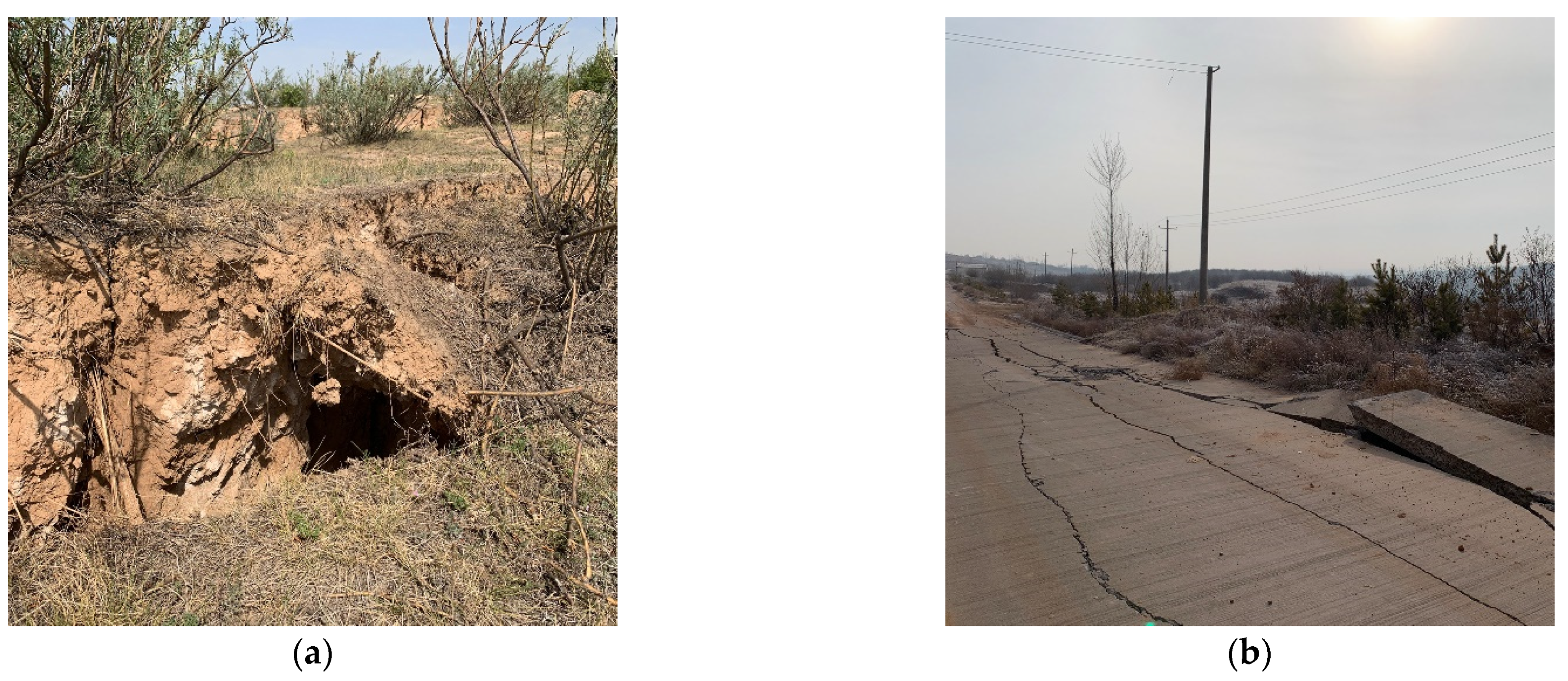
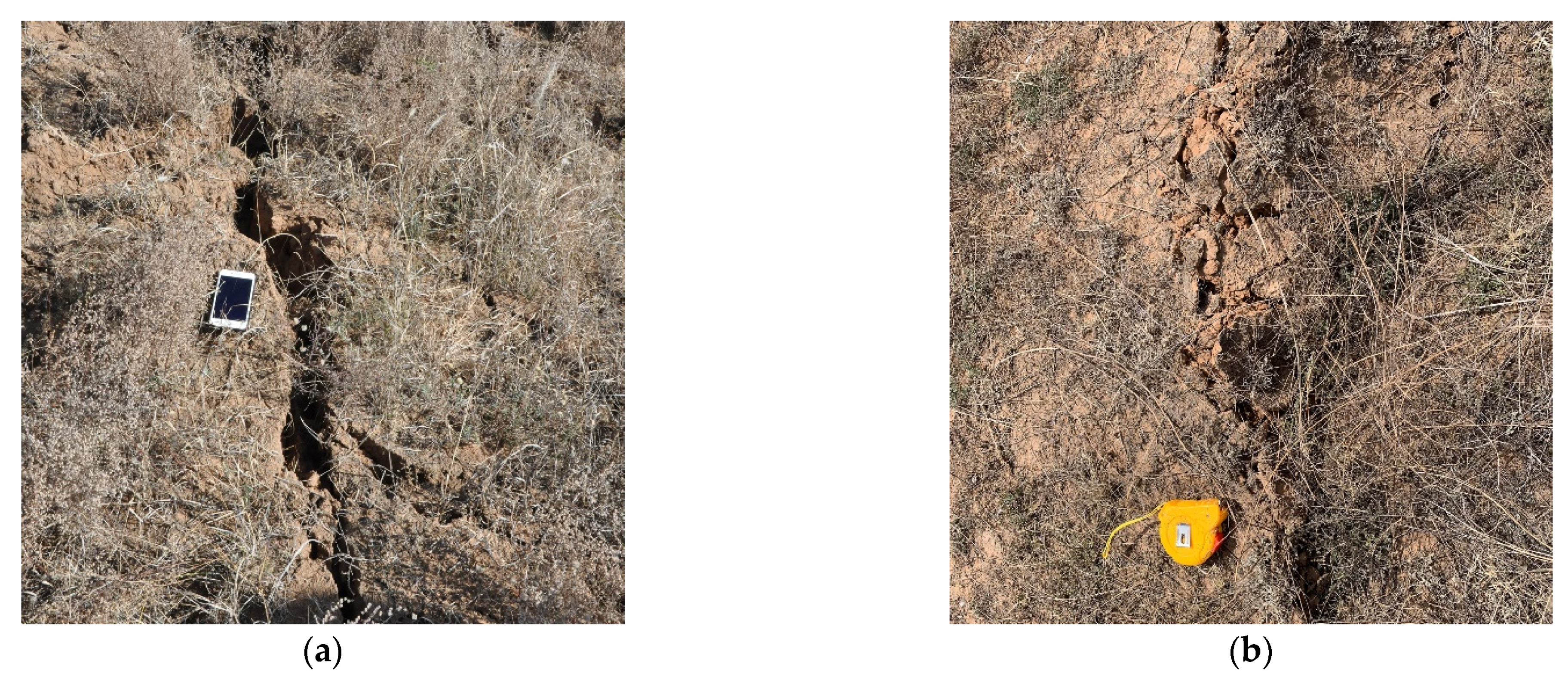
3.4.1. Coal Mining Subsidence Ground Cracks

Underground mining of coal causes changes in the original stresses in the rock and soil, resulting in rock breakage and movement as well as deformation of the topsoil layer. Non-uniform subsidence of the ground surface is the result of coupled rock breakage and topsoil layer deformation. Due to the different soil conditions and geological mining conditions, permanent and temporary cracks can exist on the surface.
Permanent cracks are caused by tensile and shear forces. In daily monitoring, permanent cracks are mainly located at the location of the open cut eyes of the working face, i.e., the position with the greatest horizontal deformation of the ground surface. The width, depth, and length of the cracks are also the largest within the working face. This type of crack often disappears within 1–2 months through the erosive force of the wind and rain. The presence of ground cracks during this time damages the growth of surface vegetation and may cause soil erosion as well as damage of the local ecology of the mine site.
In the super-sufficient mining area of the working face, the continuous advance of the working face causes rapid deformation of the overlying rock layer (Figure 9). The surface is affected by tensile and compressive deformation and most of the cracks in the affected area are “cracking-closing”, with two cracking–closing patterns occurring locally. The development of such cracks is therefore related to the position of the mining working face, and their small width and rapid changes complicate their recognition.

3.4.2. Type of Ground Fissure

The usual classification divides ground cracks into two categories, mainly according to their distribution and mechanical causes. As shown in Figure 11.
Based on mechanical causes cracks are further subdivided into three types: tensile, compressive, and torsional: (1) Tensile cracks are mainly developed in the tensile stress area and partly in the shear stress area. According to their morphology, mainly tensile, collapse, sliding, cut-down, and extraction types occur. (2) Compressive cracks are less common and generally occur in areas with large compressive deformation, manifested as bulging cracking or depression, They can be termed “Extrusion type”. (3) Torsional fractures mainly occur in the corner area of the mining area boundary. They often intersect the mining boundary obliquely and appear in bands, in the form of geese or multi-character arrangement. Sometimes they appear in the form of lattice or diamond block.
Based on the distribution dynamic fractures and marginal fractures are discriminated. Dynamic fractures exist within the workings and will disappear within a certain period of time as the workings continue to advance and as mining in the sandy areas “self-repairs”). Marginal fractures are distributed above the mining boundary and will exist for a long time at the boundary of the subsidence basin, i.e., the “O” circle of marginal fractures.

3.4.3. Distribution Characteristics of Ground Cracks

The coal mining subsidence basin area is affected by underground coal mining activities. In the stretching zone for example, the horizontal deformation value is high, the crack opening is high and permanent cracks are easily formed. During the observation period, the dynamic distribution characteristics of the location, length, width, and depth of the surface cracks on the S12013 workings were recorded in relation to the progress of recovery (Figure 12).
The distribution of surface fissures is different from that of traditional working face (Figure 13). Due to the effect of pressure relief from the cut top, the distribution of surface fissures is biased towards the side of the coal pillar free mining area and extends outward for about 105 m. The subsidence value at this point is 85.1 mm and the maximum horizontal deformation is 3.8 mm/m, which is exactly the critical value for the production of fissures in the sandy soil layer. This further proves that the production of fissures is related to coal pillar free mining. The maximum horizontal deformation was 85.1 mm/m. During the progress of the working face, the cracks in the face were closed under the influence of surface tension, compression and self-repair, without collapse steps. They existed for a short period of time, which is related to the loose fine particle structure of the overlying wind and sand layer that weaken the crack development to some extent.

3.4.4. Dynamic Fracture Development Patterns

Dynamic fractures in a workface only occur once in the “cracking-closing” cycle. However, Hu Zhenqi et al. [50,51] recognized for the first time the “M”-shaped bimodal development cycle of dynamic fractures and the self-healing feature of rapid closure at the 12406 working face of the Blianta mine in the Shendong mining area. They established a model of the dynamic fracture development cycle T as a function of mining geological conditions. During the observation period, the dynamic cracks of working face S12013 were recorded, and the dynamic cracks with atypical “M” type cycle were recognized. The cycle shown in Figure 14 was recorded for 12–18 days. The second cracking cycle accounted for 5–28% of the first cracking cycle. The cracks shown in Table 4 induce small horizontal deformation. The different overburden lithology and its structural combination may lead to the spatial and temporal variability of the development of surface discontinuous deformation.

4. Discussion

4.1. Variation of Surface Subsidence of Shallow Buried Thick Coal Seam N00 Method in Arid Windy and Sandy Areas

Coal mining destroys the original stress pattern of the overlying rock layer and modifies it. The rock layer moves and deforms from the bottom–up to reform a stable mechanical structure. However, with the expansion of the mining area, the affected area of the rock layer also increases, and the affected area of the surface and rock layer continues to expand. The influence range of the traditional mining method in the wind–sand area is within the working face, whereas the N00 method uses the coal pillarless mining technology, without coal pillar between adjacent working faces. Therefore, the influence range of mining is larger in this case.
Based on the actual measurement data from Lemon Bar Tower mine, the maximum sinkage value on the ground towards the mining area is 2649.5 mm, the maximum sinkage value on the coal pillar boundary side is −326 mm, and the maximum sinkage value above the roadway on the no coal pillar side is 1523.9 mm. In addition, the sinkage on the no coal pillar stay roadway side is larger than that on the stay coal pillar boundary side. The influence range is larger and the maximum sinkage value on the tendency line is close to the mining area side, which is the reason for no coal pillar mining.
The S12012 working face formed a mining void after mining. Due to the top cutting and unloading pressure on the side of the stay lane, a short arm beam mechanics structure was formed and the broken rock strata temporarily formed a stable structure. Although the rock was naturally compacted, the adjacent S12013 working face was mined, with no working face interval coal column protection. A certain degree of activation of the original mining area underground holes, fissures and off layers occurred. The stress balance was broken again and the short arm beam mechanical structure disappeared. The rock layer sank again, and secondary subsidence occurred on the ground.

4.2. Formation Mechanism of Distribution Characteristics of N00 Method Ground Fracture in Shallow Buried Thick Coal Seam in Arid Windy and Sandy Area

The traditional mining method of a single coal seam only produces one disturbance to the overlying rock layer. The directional roof cutting technology of N00 method without a coal pillar stay lane will induce secondary disturbance to the overlying rock layer in the adjacent working face mining area. Its surface subsidence range is expanded. The microscopic development characteristics of ground fracture cutting top pressure relief leads to a larger impact on rock transport. Therefore, the internal mechanism of the development characteristics of the edge ground fracture expansion is discussed as an example of directional top cutting pressure relief control of surface movement deformation.
The rock mass breakage, rotary motion, and ground fracture formation on the cut top side are divided into three stages (Figure 15a–c).
In first stage, rock blocks B and C became affected by the mining movement of the first mining face of 110/N00 method (S12012 working face). The ground surface sank, and tensile deformation occurred along the directional top cutting side of the air stay lane. No cracks were formed.
In the second stage, the continuous back mining of the first mining face led to the formation of a new stable structure after the collapse of the overlying rock layer. Rock blocks B and C sank significantly, while rock block B underwent significant forward rotation. Rock block C underwent reverse rotation, and tensile cracks were formed at the contact end of rock blocks A and B (i.e., along the side of the empty retention lane).
The final stage was entered after the N00 working face started back mining, stay lane lateral to the left side of the rock block directed to cut the top. Rock blocks A and B continued to sink. Rock block A was affected by minor reverse rotation and rock block B by major reverse rotation. At this time, compression deformation occurred between rock block A and B, and the ground crack closed. Synchronously, rock block C underwent a minor positive rotation. A weak tensile deformation occurred between rock blocks B and C, and cracks appeared.
Due to the directional top cutting of the roadway, it causes the rock block break down without coal pillar between adjacent working faces, resulting in the phenomenon that the ground crack expands along the tendency to the peripheral mining hollow area.

4.3. Influence of Windy Beach Terrain on the Formation of Ground Cracks

Windy beach landscapes are mostly wind-blown sand layers, which are characterized by strong looseness and non-plasticity with poor water stability and strong wet sink. Coal mining may lead to bending, breaking, and displacement deformation of the overlying rock layer in the mining area, resulting in a series of geotechnical damage changes from underground to the surface (add references). However, due to the physical properties of wind-deposited sand, mining driving force, gravitational effect of sand and soil layer, natural camp force and other factors the surface fractures can quickly close and disappear. The soil physical and chemical properties can be restored to the pre-mining level, and the surface ecology may appear to be “self-healing”.

5. Conclusions

The coal seam of the Lemon Tower coal mine (China) is shallowly buried. The surface vegetation is sparse and covered with thicker loose layers. Ground crack and ground subsidence observation was performed after the establishment of the ground movement deformation observation station. The measurements include the height of the observation point, the change of horizontal displacement, the change of width and location of ground cracks, the dynamic distribution characteristics of mining subsidence ground cracks.
Based on the compilation and the analysis of our measured data in the field, the maximum amount of surface subsidence is 5232 mm. The surface subsidence basin profile above the coal pillar boundary is steeper than that of the surface subsidence basin profile without coal pillar stay lane directional top cutting. Relevant parameters such as surface subsidence, overtopping influence angle, maximum subsidence velocity, and maximum subsidence velocity lag angle were obtained for the N00 method of shallow buried thick coal seam high-intensity mining, revealing a larger range of subsidence basins after N00 method mining. Based on this data set, the mechanism of ground subsidence caused by the N00 method is discussed. The discussion considers the activation of the rock layer in the first mining area by the 110 method mining activity.
According to the mechanism characteristics of coal mining collapse fracture formation, the observed fractures are classified as dynamic fractures, permanent fractures, tensile fractures, and compressive fractures. The distribution characteristics of coal mining ground cracks in N00 workings in the wind–sand area are different from data of previous studies. The relationship between the entire development cycle of dynamic fractures and fracture cracking and horizontal deformation in the N00 wind and sand area of Shaanxi was revealed. The fractures were characterized by analyzing the relationship between the overlying rock layer changes in the directional roof-cut mining area without coal pillar stay lane, and the formation mechanism of pulling and fracturing was determined.
In addition to our results, several issues remain to be studied. Firstly, since the N00 method is poorly applied so far, the amount of data for comparison is small, and further monitoring studies are needed. Secondly, although the surface subsidence and fissure formation mechanism of the study area has been determined, the mining geological conditions have regional differences. Therefore, the working face should be monitored under different geological mining conditions in order to deeply investigate the formation mechanism of surface cracks in coal mining by the N00 method. Thirdly, corresponding surface protection measures should be formulated for different subsidence characteristics to make them systematic, scientific, and standardized.

Author Contributions

Conceptualization, Y.F. and Z.H.; methodology, Y.F.; software, Y.F.; validation, Y.F.; formal analysis, Y.F.; investigation, Y.F., C.C., P.L., J.G., D.Y. and K.Y.; resources, Y.F.; data curation, Y.F.; writing—original draft preparation, Y.F.; writing—review and editing, Y.F.; visualization, Y.F.; project administration, Z.H. and J.S.; funding acquisition, Z.H. All authors have read and agreed to the published version of the manuscript.

Funding

This research was funded by the Research and Demonstration of Key Technology for Water Resources Protection and Utilization and Ecological Reconstruction in Coal Mining areas of Northern Shaanxi; the grant number is 2018SMHKJ-A-J-03.

Institutional Review Board Statement

Not applicable.

Informed Consent Statement

Not applicable.

Data Availability Statement

The data presented in this study are openly available.

Acknowledgments

Thanks to the Institute of Land Reclamation and Ecological Reconstruction and Shaanxi Coal Group for their help in this research.

Conflicts of Interest

The authors declare no conflict of interest.

References

  1. Jiang, Y.; Misa, R.L.; Li, P.; Yuan, X.; Sroka, A.; Jiang, Y. Summary and Development of Mining Subsidence Theory. Met. Mine 2019, 520, 7–13. [Google Scholar]
  2. Cui, X.; Gao, Y.; Yuan, D. Sudden surface collapse disasters caused by shallow partial mining in Datong coalfield, China. Nat. Hazards 2014, 74, 911–929. [Google Scholar] [CrossRef]
  3. Kratzsch, I.H. Mining subsidence engineering. Environ. Geol. Water Sci. 1986, 8, 133–136. [Google Scholar] [CrossRef]
  4. Zhao, H.; Ma, F.; Zhang, Y.; Guo, J. Monitoring and analysis of the mining-induced ground movement in the Longshou Mine, China. Rock Mech. Rock Eng. 2013, 46, 207–211. [Google Scholar] [CrossRef]
  5. Zhang, C.; Mitra, R.; Oh, J.; Hebblewhite, B. Analysis of Mining-induced Valley Closure Movements. Rock Mech. Rock Eng. 2016, 49, 1923–1941. [Google Scholar] [CrossRef]
  6. Zhou, D.; Wu, K.; Miao, X.; Li, L. Combined prediction model for mining subsidence in coal mining areas covered with thick alluvial soil layer. Bull. Eng. Geol. Environ. 2018, 77, 283–304. [Google Scholar] [CrossRef]
  7. Thongprapha, T.; Fuenkajorn, K.; Daemen, J.J.K. Study of surface subsidence above an underground opening using a trap door apparatus. Tunn. Undergr. Space Technol. 2015, 46, 94–103. [Google Scholar] [CrossRef]
  8. Yu, B.; Zhao, J.; Kuang, T.; Meng, X. In situ investigations into overburden failures of a super-thick coal seam for longwall top coal caving. Int. J. Rock Mech. Min. Sci. 2015, 78, 155–162. [Google Scholar] [CrossRef]
  9. Salmi, E.F.; Nazem, M.; Karakus, M. The effect of rock mass gradual deterioration on the mechanism of post-mining subsidence over shallow abandoned coal mines. Int. J. Rock Mech. Min. Sci. 2017, 91, 59–71. [Google Scholar] [CrossRef]
  10. Suchowerska Iwanec, A.M.; Carter, J.P.; Hambleton, J.P. Geomechanics of subsidence above single and multi-seam coal mining. J. Rock Mech. Geotech. Eng. 2016, 8, 304–313. [Google Scholar] [CrossRef] [Green Version]
  11. Vervoort, A.; Declercq, P.Y. Surface movement above old coal longwalls after mine closure. Int. J. Min. Sci. Technol. 2017, 27, 481–490. [Google Scholar] [CrossRef]
  12. Sasaoka, T.; Takamoto, H.; Shimada, H.; Oya, J.; Hamanaka, A.; Matsui, K. Surface subsidence due to underground mining operation under weak geological condition in Indonesia. J. Rock Mech. Geotech. Eng. 2015, 7, 337–344. [Google Scholar] [CrossRef] [Green Version]
  13. Li, W.X.; Wen, L.; Liu, X.M. Ground movements caused by deep underground mining in Guan-Zhuang iron mine, Luzhong, China. Int. J. Appl. Earth Obs. Geoinf. 2010, 12, 175–182. [Google Scholar] [CrossRef]
  14. Zhang, W.; Zhang, D.S.; Wu, L.X.; Wang, H.Z. On-site radon detection of mining-induced fractures from overlying strata to the surface: A case study of the Baoshan coal mine in China. Energies 2014, 7, 8483–8507. [Google Scholar] [CrossRef] [Green Version]
  15. Sun, Q.; Zhang, J.; Zhang, Q.; Zhao, X. Analysis and prevention of geo-environmental hazards with high-intensive coal mining: A case study in China’s western eco-environment frangible area. Energies 2017, 10, 786. [Google Scholar] [CrossRef]
  16. Can, E.; Mekik, Ç.; Kuşçu, Ş.; Akçin, H. Computation of subsidence parameters resulting from layer movements post-operations of underground mining. J. Struct. Geol. 2013, 47, 16–24. [Google Scholar] [CrossRef]
  17. Singh, G.S.P. Conventional approaches for assessment of caving behaviour and support requirement with regard to strata control experiences in longwall workings. J. Rock Mech. Geotech. Eng. 2015, 7, 291–297. [Google Scholar] [CrossRef] [Green Version]
  18. Manekar, G.G.; Shome, D.; Chaudhari, M.P. Prediction of Subsidence Parameters & 3-D Analysis at Balaghat Underground Manganese Mine of MOIL Limited, India. Procedia Eng. 2017, 191, 1075–1086. [Google Scholar] [CrossRef]
  19. Zhu, D.; Tu, S. Mechanisms of support failure induced by repeated mining under gobs created by two-seam room mining and prevention measures. Eng. Fail. Anal. 2017, 82, 161–178. [Google Scholar] [CrossRef]
  20. Kan, W.; Liang, L.; Xiang-lei, W.; Lian-gui, Z.; Zong-sheng, W.; Xin-min, S. Research of ground cracks caused by fully-mechanized sublevel caving mining based on field survey. Procedia Earth Planet. Sci. 2009, 1, 1095–1100. [Google Scholar] [CrossRef] [Green Version]
  21. Bouwer, H. Land Subsidence and Cracking Due to Ground-Water Depletion. Ground Water 1977, 15, 358–364. [Google Scholar] [CrossRef]
  22. Akagi, T. Some land subsidence experiences in Japan and their relevance to subsidence in Bangkok, Thailand. Geotech. Eng. 1979, 10, 1–48. [Google Scholar]
  23. Phien-Wej, N.; Giao, P.H.; Nutalaya, P. Land subsidence in Bangkok, Thailand. Eng. Geol. 2006, 82, 187–201. [Google Scholar] [CrossRef]
  24. Rozos, D.; Sideri, D.; Loupasakis, C.; Apostolidis, E. Land subsidence due to excessive ground water withdrawal. A case study from Stavros-Farsala site, West Thessaly Greece. Bull. Geol. Soc. Greece 2017, 43, 1850–18570. [Google Scholar] [CrossRef] [Green Version]
  25. Ghazifard, A.; Akbari, E.; Shirani, K.; Safaei, H. Evaluating land subsidence by field survey and D-InSAR technique in Damaneh City, Iran. J. Arid. Land 2017, 9, 778–789. [Google Scholar] [CrossRef]
  26. Sepe, V.; Atzori, S.; Ventura, G. Subsidence due to crack closure and depressurization of hydrothermal systems: A case study from Mt Epomeo (Ischia Island, Italy). Terra Nova 2007, 19, 127–132. [Google Scholar] [CrossRef]
  27. Ide, T.S.; Pollard, D.; Orr, F.M. Fissure formation and subsurface subsidence in a coalbed fire. Int. J. Rock Mech. Min. Sci. 2010, 47, 81–93. [Google Scholar] [CrossRef]
  28. Trivino, L.; Mohanty, B. Assessment of crack initiation and propagation in rock from explosion-induced stress waves and gas expansion by cross-hole seismometry and FEM–DEM method. Int. J. Rock Mech. Min. Sci. 2015, 77, 287–299. [Google Scholar] [CrossRef]
  29. Abdallah, M.; Verdel, T. Behavior of a masonry wall subjected to mining subsidence, as analyzed by experimental designs and response surfaces. Int. J. Rock Mech. Min. Sci. 2017, 100, 199–206. [Google Scholar] [CrossRef]
  30. Graff, J.V.; Romesburg, H.C. Subsidence crack closure: Rate, magnitude, and sequence. Bull. Int. Assoc. Eng. Geol. 1981, 23, 123–127. [Google Scholar] [CrossRef]
  31. Thompson, J.A.; Lamb, D.W.; Frazier, P.S.; Ellem, B. Monitoring the effects of longwall mine-induced subsidence on vineyards. Environ. Earth Sci. 2010, 62, 973–984. [Google Scholar] [CrossRef]
  32. Dawei, Z.; Kan, W.; Zhihui, B.; Zhenqi, H.; Liang, L.; Yuankun, X.; Xinpeng, D. Formation and development mechanism of ground crack caused by coal mining: Effects of overlying key strata. Bull. Int. Assoc. Eng. Geol. 2017, 78, 1025–1044. [Google Scholar] [CrossRef]
  33. Deng, Y.; Chen, C.; Xia, K.; Pang, H.; Sun, C.; Yang, K.; Zheng, X. Investigation on the distribution characteristics of ground cracks in the Chengchao Iron Mine, China. Environ. Earth Sci. 2019, 78, 280. [Google Scholar] [CrossRef]
  34. Xu, Y.; Wu, K.; Bai, Z.; Hu, Z. Theoretical analysis of the secondary development of mining-induced surface cracks in the Ordos region. Environ. Earth Sci. 2017, 76, 703. [Google Scholar] [CrossRef]
  35. Xu, Y.; Wu, K.; Li, L.; Zhou, D.; Hu, Z. Ground cracks development and characteristics of strata movement under fast excavation: A case study at Bulianta coal mine, China. Bull. Int. Assoc. Eng. Geol. 2017, 78, 325–340. [Google Scholar] [CrossRef]
  36. Li, L.; Wu, K.; Hu, Z.; Xu, Y.; Zhou, D. Analysis of developmental features and causes of the ground cracks induced by oversized working face mining in an aeolian sand area. Environ. Earth Sci. 2017, 76, 135. [Google Scholar] [CrossRef]
  37. Zhu, G.H.; Lian, D.J. Analysis on mining-induced cumulative effective of surface cracks in mining areas. J. Saf. Sci. Technol. 2012, 8, 47–51. [Google Scholar]
  38. Yang, X.; Wen, G.; Dai, L.; Sun, H.; Li, X. Ground Subsidence and Surface Cracks Evolution from Shallow-Buried Close-Distance Multi-seam Mining: A Case Study in Bulianta Coal Mine. Rock Mech. Rock Eng. 2019, 52, 2835–2852. [Google Scholar] [CrossRef]
  39. Wu, S.C.; Han, L.Q.; Li, Z.P.; Guo, C.; Zhou, J.X. Discussion on the methods for determining slope safety factor based on stress state of the sliding surface. J. China Univ. Min. Technol. 2018, 47, 719–726. [Google Scholar]
  40. Ma, L.; Zhang, D.; Sun, G.; Cui, T.; Zhou, T. Thick alluvium full-mechanized caving mining with large mining height face roof control mechanism and practice. J. China Coal Soc. 2013, 38, 199–203. [Google Scholar]
  41. Xuan, Y.Q. Research on movement and evolution law of breaking of overlying strata in shallow coal seam with a thin bedrock. Rock Soil Mech. 2008, 29, 512–516. [Google Scholar]
  42. Wang, R.; Ma, S.; Zhang, H.; Xu, C.; Guo, Z. Effects of Surface Cracks Caused by High Intensity Coal Mining on Soil Microbial Characteristics and Plant Communities in Arid Regions. Res. Environ. 2016, 29, 1249–1255. [Google Scholar]
  43. Wang, L.; Wei, S.P.; Wang, Q.J. Effect of coal exploitation on groundwater and vegetation in the Yushenfu Coal Mine. J. China Coal Soc. 2008, 33, 1408–1414. [Google Scholar]
  44. Manchao, H.; Yubing, G.; Jun, Y.; Jianwen, W.; Yajun, W.; Zhen, Z. Engineering experimentation of gob-side entry retaining formed by roof cutting and pressure release in a thick-seam fast-extracted mining face. Rock Soil Mech. 2018, 39, 254–264. [Google Scholar]
  45. Manchao, H.; Yubing, G.; Jun, Y.; Zhibiao, G.; Eryu, W.; Yajun, W. An energy-gathered roof cutting technique in no-pillar mining and its impact on stress variation in surrounding rocks. Chinese J. Rock Mech. Eng. 2017, 36, 1314–1325. [Google Scholar]
  46. Manchao, H.; Xingen, M.; Jiong, W.; Jiabin, Z.; Yunxing, L. Feature analysis of working face strata pressure with roof cutting pressure releasing in medium-thick seam and compound roof condition. Chinese J. Rock Mech. Eng. 2018, 37, 2425–2434. [Google Scholar]
  47. Polanin, P.; Kowalski, A.; Walentek, A. Numerical simulation of subsidence caused by roadway system. Arch. Min. Sci. 2019, 64, 385–397. [Google Scholar] [CrossRef]
  48. Ziȩba, M.; Kalisz, P.; Grygierek, M. The impact of mining deformations on road pavements reinforced with geosynthetics. Arch. Min. Sci. 2020, 65, 751–767. [Google Scholar] [CrossRef]
  49. Kowalski, A.; Biaek, J.; Rutkowski, T. Caulking of goafs formed by cave-in mining and its impact on surface subsidence in hard coal mines. Arch. Min. Sci. 2021, 66, 85–100. [Google Scholar]
  50. Wang, X.-J.; Hu, Z.-Q.; Hu, Q.-F.; Chen, C. Evolution and self-healing characteristic of land ecological environment due to super-large coalface mining in windy and sandy region. J. China Coal Soc. 2015, 40, 2166–2172. [Google Scholar] [CrossRef]
  51. Hu, Z.-Q.; Long, J.-H.; Wang, X.-J. Self-healing, natural restoration and artificial restoration of ecological environment for coal mining. J. China Coal Soc. 2014, 39, 1751–1757. [Google Scholar] [CrossRef]
Figure 1. Study site. (a,b) Location of the Ningtiaota mine in China; (c) roadway layout of S12013 working face and positional relationship surface observation stations.
Energies 14 07712 g001
Figure 2. Surface damage from coal mining subsidence (a) crack damage to plant roots; (b) damage to mine roads from cracks.
Energies 14 07712 g002
Figure 3. Subsidence curve of line A.
Energies 14 07712 g003
Figure 4. Tilt deformation value curve of line A.
Energies 14 07712 g004
Figure 5. Curve of curvature deformation value of line A.
Energies 14 07712 g005
Figure 6. Subsidence curve of line B.
Energies 14 07712 g006
Figure 7. Tilt curve of line B.
Energies 14 07712 g007
Figure 8. Curvature of line B.
Energies 14 07712 g008
Figure 9. Diagram of coal mining subsidence advance influence.
Energies 14 07712 g009
Figure 10. Diagram of the subsidence velocity of coal mining subsidence.
Energies 14 07712 g010
Figure 11. Mining ground cracks. (a) Cracks from tensile effects and (b) cracks from compressive effects.
Energies 14 07712 g011
Figure 12. Daliuta 52305 planes of fissures in different time series.
Energies 14 07712 g012
Figure 13. Ningtiaota S12013 planes of fissures in different time series.
Energies 14 07712 g013
Figure 14. S12013 the development lifecycle of dynamic fissures.
Energies 14 07712 g014
Figure 15. Mechanism of surface fracture development (a) deformation of the ground surface, (b) cracking for the first time, (c) cracking secondary cracking.
Energies 14 07712 g015
Table 1. Similar material parameters in panel S12013.
LithologyHeight (m)Depth (m)Density (kg/m3)Compressive Strength (MPa)
Aeolian sand7.57.5--
Silty sandy soil7.8815.38--
Red soil31.1646.54--
Fine-grained sandstone5.6752.21251036.65
Sandy mudstone2.4254.63210146.45
Fine-grained sandstone7.5862.21224147.98
Coarse-grained sandstone1.9464.15248010
Siltstone15.9780.12254046.22
Medium-grained sandstone13.4893.6220823
Fine-grained sandstone6.1599.75260040.96
1–2 Upper coal seam2.9102.65--
Siltstone4.8107.45258050.17
Coal seam0.45107.9--
Siltstone0.9108.8258050.47
Coal seam0.25109.05--
Siltstone4.43113.48258051.03
1–2 Lower coal seam1.67115.15--
Fine-grained sandstone9.37124.52260046.57
Medium-grained sandstone18.58143.1227045.27
Siltstone0.78143.88256050.88
2–2 coal seam4.04147.92134044.07
Table 2. Observation point spacing.
Depth of Mining (m)<5050–100100–200200–300300–400>400
Distance between points (m)51015202530
Table 3. Comparison of mining conditions and angular volume parameters for surface deformation.
ZoneCoal
Thickness (m)
Inclination
Angle (°)
Tendency
Length (m)
Subsidence
Coefficient
Displacement Angle (°)
District RiseDistrict Down
Ningtiaota Ming S12013 working face41–2333.40.6673.351.3
Bulianta Ming 12406 working face4.811–3300.50.5585.180.6
Table 4. Comparison of dynamic fissures parameters.
Workface NameLoose Layer SoilMaximum Width (mm)Lifecycle (d)Basal Mining RatioHorizontal Deformation (mm/m)Advance Speed (m/d)
Ningtiaota S12013Sand5712–19222.7–3.512
Publisher’s Note: MDPI stays neutral with regard to jurisdictional claims in published maps and institutional affiliations.

